1
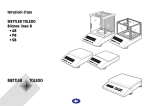
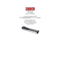
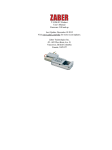
XY_XYZ_Stages Product
User's Manual
Firmware 5.00 and up
Last Update: December 10 2015
Visit www.zaber.com/wiki for more recent updates.
Zaber Technologies Inc.
#2 - 605 West Kent Ave. N.
Vancouver, British Columbia
Canada, V6P 6T7
Table of Contents
Disclaimer...........................................................................................................................................................1
Assembly/Mounting...........................................................................................................................................2
XY T-LS Stages......................................................................................................................................2
T-LS load spring...............................................................................................................................3
XY & XYZ X-LSM Stages.....................................................................................................................3
XY & XYZ T-LSR or X-LSQ Stages.....................................................................................................5
XY & XYZ A-LST Stages......................................................................................................................7
Alignment............................................................................................................................................................9
Operation..........................................................................................................................................................11
i
Disclaimer
Zaber’s devices are not intended for use in any critical medical, aviation, or military applications or situations
where a product's use or failure could cause personal injury, death, or damage to property. Zaber disclaims
any and all liability for injury or other damages resulting from the use of our products.
Disclaimer
1
Assembly/Mounting
All XY and XYZ stages are shipped disassembled to prevent damage to moving parts during transportation.
Please find your model below for specific assembly instructions. Please note that the figures shown below
represent only one of a number of possible mounting configurations. They are meant only as an example to
show the general mounting procedures.
XY T-LS Stages
X and Y-axis T-LS stages are attached to each other using clearance holes in the base and threaded holes in
the carriage top. In order to gain access to the holes in the base, the carriage will need to be moved. The two
large access holes in the carriage should line up with the holes in the stage base (see figure 1).
Figure 1 - T-LS access holes aligned with bolt holes in stage base.
Once the access holes are aligned, 2 bolts can be inserted through the top stage and screwed into the mounting
holes of the lower stage's carriage (see figure 2).
Assembly/Mounting
2
Figure 2 - XY-T-LS stage showing mounting bolts.
T-LS load spring
T-LS linear stages contain a spring which applies a light load against the leadscrew. Typically these stages are
used in a horizontal orientation, and the only force experienced by the leadscrew is the spring force, which
serves to keep the load on the leadscrew always in the same direction, thus reducing backlash. If used in a
vertical orientation, the spring is not needed to reduce backlash since the load (the weight of the stage and
whatever may be mounted to it) is always in the same direction by default. In fact, if the load is greater than
the minimum spring force and less than the maximum spring force, the existence of the spring will actually
introduce backlash since there will be a point in the stage travel where the load on the leadscrew changes
direction. Therefore, when using T-LS stages in a vertical orientation, we recommend removing the spring
from the stage. This can be done relatively easily using a small hook fashioned from a paperclip to slip the
spring off its mounting posts and slide it out of the stage. It may help to fully extend the stage prior to spring
removal.
XY & XYZ X-LSM Stages
X and Y-axis X-LSM stages are attached to each other using clearance holes in the base and threaded holes in
the carriage top. In order to gain access to the holes in the base, the carriage may need to be moved. Two large
holes in the carriage allow access to the stage base in cases when the carriage motion is limited (see figure 1).
XY T-LS Stages
3
Figure 1 - T-LSM access holes aligned with bolt holes in stage base.
Once the access holes are aligned, bolts can be inserted through the top stage and screwed into the mounting
holes of the lower stage's carriage. It is advisable to use 4 bolts for the X to Y stage connection to prevent
slippage. See figure 2 for an sample X-XY-LSM configuration.
Figure 2 - X-XY-LSM025
If a Z-axis is to be added to the stage, the 2 holes in the Z stage end plate are used to bolt it to the carriage of
the lower stage. (see figure 3).
Figure 3 - X-XYZ-LSM025
XY & XYZ X-LSM Stages
4
XY & XYZ T-LSR or X-LSQ Stages
X and Y-axis T-LSR or X-LSQ stages are attached to each other using M6 bolts that pass through the slotted
holes in the base and thread into the carriage of the lower stage. It may be necessary to move the carriage in
order to gain access to the holes in the base of the stage.
Figure 1 - X-XY-LSQ stage
If a Z-axis is to be added to the stage, the two holes in the stage end plate are used to bolt the Z-axis stage to
the carriage of the lower stage. See figures 2 and 3 for sample configurations.
XY & XYZ T-LSR or X-LSQ Stages
5
Figure 2 - X-XZ-LSQ stage
This image shows three X-LSQ-E linear stages in XYZ configuration. The three devices are daisy-chained.
Just connect this system to your computer or joystick, plug in the power supplies, and start positioning.
Figure 3 - X-XYZ-LSQ stage
XY & XYZ T-LSR or X-LSQ Stages
6
XY & XYZ A-LST Stages
X and Y-axis A-LST stages are attached to each other using the M6 screws included. The screws pass through
the clearance holes in the stage base and thread into the carriage of the lower stage. If using longer screws
than the ones included, make sure that they do not go too far through the lower carriage and interfere with the
stage mechanics. It may be necessary to move the carriage to gain access to the holes in the stage base.
Figure 1 - XY-A-LST stage
If a Z-axis is to be added to the assembly an angle bracket (product number: AB104) is required. The slotted
holes in the angle bracket should be lined up with the threaded holes in the y- axis carriage and attached with
the included M6 screws. Be sure to position the angle bracket with enough room for the z-axis stage to attach
without contacting one of the other stages. To attach the z-axis, sit the z-stage onto the y-stage carriage, then
line up the clearance holes on the base of the stage with the threaded holes on the angle bracket and bolt them
together. It may be necessary to move the carriage to gain access to the holes in the stage base.
Figure 2 - Close up of angle bracket attached to z and y-axis stages
XY & XYZ A-LST Stages
7
This shows a typical XYZ orientation. The z- axis stage can also be rotated 90 deg to overhang the y-axis
stage.
Figure 3 - XYZ-A-LST stage
XY & XYZ A-LST Stages
8
Alignment
Note that the following procedures are intended only as a guide to help you align your multi-axis system. The
specifics of aligning your stages will vary according to your setup. A machinist's square is required for these
procedures.
First, loosely attach lower axis stage to breadboard using mounting bolts.
Figure 1 - Loosely mounting the lower-axis to the breadboard.
Then, use a machinist's square to align the lower axis stage with an edge of the breadboard and tighten the
mounting screws.
Figure 2 - Aligning lower axis.
Next, loosely attach the next axis and align the bases of these two stages using the machinist's square as
shown. When the stages are aligned, tighten the mounting screws.
Alignment
9
Figure 3 - Aligning upper axis.
If a Z-axis is to be used, install it loosely as shown in figure 4.
Figure 4 - Loosely mounting Z-axis.
Use the machinist's square as a straight edge to align the Z-axis stage with the carriage of the stage it is
attached to. It may help to have a small amount of tension on the mounting screws, so the z-axis stage can be
moved, but with a little resistance. When it is aligned, tighten the screws.
Figure 5 - Aligning Z-axis.
Alignment
10
Operation
Refer to the specific stage instructions for operating the stages. All instructions can be found here.
Operation
11