1
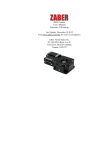
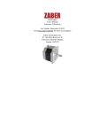
G-LSQ Product
User's Manual
Firmware 5.00 and up
Last Update: December 10 2015
Visit www.zaber.com/wiki for more recent updates.
Zaber Technologies Inc.
#2 - 605 West Kent Ave. N.
Vancouver, British Columbia
Canada, V6P 6T7
Table of Contents
Disclaimer...........................................................................................................................................................1
Precautions.........................................................................................................................................................2
Maintenance............................................................................................................................................2
Operation............................................................................................................................................................3
Tensioning Timing Belt and Aligning Lower Axis Stages..............................................................................4
Parts Identification..................................................................................................................................4
Alignment Procedure..............................................................................................................................4
Warranty and Repair........................................................................................................................................9
Standard products....................................................................................................................................9
Custom products.....................................................................................................................................9
How to return products...........................................................................................................................9
Email Updates..................................................................................................................................................10
Contact Information........................................................................................................................................11
Appendix A: Default Settings.........................................................................................................................12
Appendix B: Device Specifications.................................................................................................................13
Comparison - G-LSQ Series..................................................................................................................14
i
Disclaimer
Zaber’s devices are not intended for use in any critical medical, aviation, or military applications or situations
where a product's use or failure could cause personal injury, death, or damage to property. Zaber disclaims
any and all liability for injury or other damages resulting from the use of our products.
Disclaimer
1
Precautions
Zaber's linear stages can produce enough force to cause personal injury. Be careful to not get body parts
caught between the moving carriage and the end plates of the stage. Make sure that no loose clothing gets
caught in the rotating lead screw.
Maintenance
Teflon-coated (black) lead screws are not designed to be greased. Normally no lubrication is required over the
lifetime of the device. If a squeaking sound develops in the lead screw, Super Lube oil with PTFE (Product
number #51004) can be applied. Apply a very thin bead over 80% of the contact surface of the lead screw and
run the stage slowly from end to end. Wipe off any excess.
Precautions
2
Operation
The G-LSQ stages are designed to be controlled with any of Zaber's multi-axis X-Series or A-Series Stepper
Motor Controllers. Zaber's controllers and peripherals are designed for ease of use when used together.
Optimal settings for each peripheral (such as the default current, speed, acceleration, and limit settings) can be
loaded by setting the peripheralid (T:66) on the controller. The peripheral ID is listed as the ID on the
peripheral's label. A list of IDs is also available on the ID Mapping page. For more information on device
operation, refer to the controller's user manual.
Operation
3
Tensioning Timing Belt and Aligning Lower Axis
Stages
If the lower axis of a G-LSQ gantry system needs to be re-aligned, follow the instructions below.
Parts Identification
G-LSQ Gantry System Components
Alignment Procedure
• Move lower and upper axes stages to a position where all the screws holding the stages to the
baseplate and cross-member are accessible.
• Remove top stage.
Upper axis stage removed
Tensioning Timing Belt and Aligning Lower Axis Stages
4
• Loosen cross-member screws.
Loosen cross-member screws
• Remove timing belt cover.
Remove timing belt cover
• Loosen the screws holding the lower axis stages to the baseplate by about 1/4 turn.
Loosen mounting screws on both master and slave stages
• Slide slave stage towards master stage to release tension on timing belt.
• Check that dowel pins are installed (3 for master stage, 1 for slave).
Alignment Procedure
5
2 dowel pins should be installed near the motor end of the master stage
1 dowel pin should be installed near the far end of the master stage
1 dowel pin should be installed near the motor end of the slave stage
• If dowel pins are not installed, install them. They should need only a light tap to insert. Use only
3/32" dowel pins.
• Push master stage against dowel pins and tighten screws holding stage to baseplate
• While holding slave stage against dowel pin, slide the stage away from the master stage until the
timing belt is taught. Try to keep the stage as parallel to the master stage as possible. While holding
the stage in position, tighten one of the screws near the motor end of the stage and one screw near the
opposite end of the stage. Don't worry that the stages are not perfectly parallel. They will be aligned
in the following steps.
Alignment Procedure
6
Tension the timing belt and tighten the mounting screws on the slave stage
• Tighten the cross-member to master stage screws. Leave the screws on the slave stage side loose.
Tighten the cross-memeber to master stage screws
• Re-install the top axis stage.
Re-install the upper axis stage
• Move the lower axis to the home position.
• Tighten the cross-member to slave stage screws.
• Loosen the screw you previously tightened near the maximum travel position of the slave stage. Both
screws at this end of the stage should now be loose.
Alignment Procedure
7
• Using the controller pot knob, move the lower axis towards the maximum travel position. The
cross-member should move the slave stage into alignment with the master. When the cross-member
gets close to the end of travel, stop the movement and tighten one of the screws at the far end of the
slave stage to hold it in position.
• As the alignment of the slave stage changes, you will notice that the belt tension will change as well.
The proper timing belt tension is very important for proper operation of the gantry system. If the belt
is too tight, the lower axis may not be able to reach its maximum speed and the motor bearings will
wear out prematurely. If it is too loose, the backlash will increase. See the table below for the
maximum speed of your gantry system when the timing belt is properly tensioned. The maximum
speed is a good indication of proper tension. If the belt tension needs to be adjusted, loosen the
cross-member screws and the mounting screws near the motor end of the slave stage and swing this
end of the stage towards or away from the master stage as necessary to adjust the belt tension. Tighten
one of the screws and repeat the alignment process described above. Properly tensioning the belt and
aligning the slave stage is an iterative process and make take several tries to get right.
• Re-install the timing belt cover.
Speed Range for Gantry with Properly Tensioned Timing Belt Using T-MCA Controller
Gantry System
G-LSQxxxAxxxA
G-LSQxxxBxxxB
G-LSQxxxDxxxD
Maximum Speed
30000-32000
30000-32000
18000-20000
Alignment Procedure
8
Warranty and Repair
For Zaber's policies on warranty and repair, please refer to the Ordering Policies
Standard products
Standard products are any part numbers that do not contain the suffix ENG followed by a 4 digit number.
Most, but not all, standard products are listed for sale on our website. All standard Zaber products are backed
by a one-month satisfaction guarantee. If you are not satisfied with your purchase, we will refund your
payment minus any shipping charges. Goods must be in brand new saleable condition with no marks. Zaber
products are guaranteed for one year. During this period Zaber will repair any products with faults due to
manufacturing defects, free of charge.
Custom products
Custom products are any part numbers containing the suffix ENG followed by a 4 digit number. Each of these
products has been designed for a custom application for a particular customer. Custom products are
guaranteed for one year, unless explicitly stated otherwise. During this period Zaber will repair any products
with faults due to manufacturing defects, free of charge.
How to return products
Customers with devices in need of return or repair should contact Zaber to obtain an RMA form which must
be filled out and sent back to us to receive an RMA number. The RMA form contains instructions for packing
and returning the device. The specified RMA number must be included on the shipment to ensure timely
processing.
Warranty and Repair
9
Email Updates
If you would like to receive our periodic email newsletter including product updates and promotions, please
sign up online at www.zaber.com (news section). Newsletters typically include a promotional offer worth at
least $100.
Email Updates
10
Contact Information
Contact Zaber Technologies Inc by any of the following methods:
Phone 1-604-569-3780 (direct)
1-888-276-8033 (toll free in North America)
Fax 1-604-648-8033
Mail #2 - 605 West Kent Ave. N., Vancouver, British Columbia, Canada, V6P 6T7
Web www.zaber.com
Email Please visit our website for up to date email contact information.
The original instructions for this product are available at http://www.zaber.com/wiki/Manuals/G-LSQ.
Contact Information
11
Appendix A: Default Settings
see our website
Appendix A: Default Settings
12
Appendix B: Device Specifications
For complete device specifications for G-LSQ gantries please see our website.
Appendix B: Device Specifications
13
Specification
Integrated Controller
Recommended Controller
Repeatability
Encoder Type
Maximum Centered Load
Maximum Cantilever Load
Guide Type
Maximum Current Draw
Motor Steps Per Rev
Motor Type
Motor Rated Current
Motor Winding Resistance
Inductance
Motor Rated Power
Motor Connection
Mechanical Drive System
Limit or Home Sensing
Axes of Motion
Mounting Interface
Operating Temperature Range
Stage Parallelism
RoHS Compliant
CE Compliant
Value
Alternate Unit
No
X-MCB2 (48 V) Included
< 4 µm
None
180 N
800 N-cm
Roller Bearing
1200 mA
200
Stepper (2 phase)
1200 mA/phase
3.3 ohms/phase
2.8 mH/phase
9.6 Watts
D-sub 15
Precision lead screw
Magnetic home sensor
2
M6 threaded holes and 8-32 threaded holes
0 to 50 degrees C
< 100 µm
Yes
Yes
< 0.000157 "
40.4 lb
1,132.9 oz-in
< 0.003937 "
Comparison - G-LSQ Series
Part Number
Microstep Size (Default Resolution)
G-LSQ150A150A-T4 0.09921875 µm
G-LSQ150B150B-T4
Travel Range Accuracy (unidirectional)
Backlash
150 x 150 mm 45 µm
< 8 µm
( 5.906 ")
( 0.001772 ")
(< 0.000315 ")
0.49609375 µm
Comparison - G-LSQ Series
14
150 x 150 mm 15 µm
( 5.906 ")
( 0.000591 ")
150 x 150 mm 15 µm
G-LSQ150D150D-T4 1.984375 µm
( 5.906 ")
( 0.000591 ")
300 x 300 mm 90 µm
G-LSQ300A300A-T4 0.09921875 µm
( 11.811 ")
( 0.003543 ")
300 x 300 mm 30 µm
G-LSQ300B300B-T4 0.49609375 µm
( 11.811 ")
( 0.001181 ")
300 x 300 mm 30 µm
G-LSQ300D300D-T4 1.984375 µm
( 11.811 ")
( 0.001181 ")
450 x 450 mm 135 µm
G-LSQ450A450A-T4 0.09921875 µm
( 17.717 ")
( 0.005315 ")
450 x 450 mm 45 µm
G-LSQ450B450B-T4 0.49609375 µm
( 17.717 ")
( 0.001772 ")
450 x 450 mm 45 µm
G-LSQ450D450D-T4 1.984375 µm
( 17.717 ")
( 0.001772 ")
Part Number
Maximum Speed Minimum Speed Speed Resolution Peak Thrust
23 mm/s
0.00093 mm/s
0.00093 mm/s
140 N
G-LSQ150A150A-T4
( 0.906 "/s)
( 0.00004 "/s)
( 0.00004 "/s)
( 31.4 lb)
120 mm/s
0.00465 mm/s
0.00465 mm/s
70 N
G-LSQ150B150B-T4
( 4.724 "/s)
( 0.00018 "/s)
( 0.00018 "/s)
( 15.7 lb)
330 mm/s
0.0186 mm/s
0.0186 mm/s
10 N
G-LSQ150D150D-T4
( 12.992 "/s)
( 0.00073 "/s)
( 0.00073 "/s)
( 2.2 lb)
23 mm/s
0.00093 mm/s
0.00093 mm/s
140 N
G-LSQ300A300A-T4
( 0.906 "/s)
( 0.00004 "/s)
( 0.00004 "/s)
( 31.4 lb)
120 mm/s
0.00465 mm/s
0.00465 mm/s
70 N
G-LSQ300B300B-T4
( 4.724 "/s)
( 0.00018 "/s)
( 0.00018 "/s)
( 15.7 lb)
330 mm/s
0.0186 mm/s
0.0186 mm/s
10 N
G-LSQ300D300D-T4
( 12.992 "/s)
( 0.00073 "/s)
( 0.00073 "/s)
( 2.2 lb)
23 mm/s
0.00093 mm/s
0.00093 mm/s
140 N
G-LSQ450A450A-T4
( 0.906 "/s)
( 0.00004 "/s)
( 0.00004 "/s)
( 31.4 lb)
G-LSQ450B450B-T4
Comparison - G-LSQ Series
< 20 µm
(< 0.000787 ")
< 80 µm
(< 0.003150 ")
< 8 µm
(< 0.000315 ")
< 20 µm
(< 0.000787 ")
< 80 µm
(< 0.003150 ")
< 8 µm
(< 0.000315 ")
< 20 µm
(< 0.000787 ")
< 80 µm
(< 0.003150 ")
15
G-LSQ450D450D-T4
Part Number
G-LSQ150A150A-T4
G-LSQ150B150B-T4
G-LSQ150D150D-T4
G-LSQ300A300A-T4
G-LSQ300B300B-T4
G-LSQ300D300D-T4
G-LSQ450A450A-T4
G-LSQ450B450B-T4
G-LSQ450D450D-T4
120 mm/s
0.00465 mm/s
0.00465 mm/s
70 N
( 4.724 "/s)
( 0.00018 "/s)
( 0.00018 "/s)
( 15.7 lb)
330 mm/s
0.0186 mm/s
0.0186 mm/s
10 N
( 12.992 "/s)
( 0.00073 "/s)
( 0.00073 "/s)
( 2.2 lb)
Maximum Continuous Thrust Vertical Runout Linear Motion Per Motor Rev
100 N
< 13 µm
1.27 mm
( 22.4 lb)
(< 0.000512 ")
( 0.050 ")
70 N
< 13 µm
6.35 mm
( 15.7 lb)
(< 0.000512 ")
( 0.250 ")
10 N
< 50 µm
25.4 mm
( 2.2 lb)
(< 0.001969 ")
( 1.000 ")
70 N
< 13 µm
1.27 mm
( 15.7 lb)
(< 0.000512 ")
( 0.050 ")
70 N
< 13 µm
6.35 mm
( 15.7 lb)
(< 0.000512 ")
( 0.250 ")
10 N
< 76 µm
25.4 mm
( 2.2 lb)
(< 0.002992 ")
( 1.000 ")
140 N
< 13 µm
1.27 mm
( 31.4 lb)
(< 0.000512 ")
( 0.050 ")
100 N
< 13 µm
6.35 mm
( 22.4 lb)
(< 0.000512 ")
( 0.250 ")
10 N
< 200 µm
25.4 mm
( 2.2 lb)
(< 0.007874 ")
( 1.000 ")
Comparison - G-LSQ Series
Weight
10.41 kg
10.41 kg
10.41 kg
17.51 kg
17.51 kg
17.51 kg
25.62 kg
25.62 kg
25.62 kg
16