1
User Manual
(UDTTV02 GPS Tracker )
v2.1
Table of Contents
Introduction .............................................................................................................................................................4
Applications.............................................................................................................................................................4
Caution....................................................................................................................................................................4
Technical Specification............................................................................................................................................5
Key Features:..............................................................................................................................................5
Specification ................................................................................................................................................6
Interface & LED.......................................................................................................................................................7
LED Status ..................................................................................................................................................7
Installation ...............................................................................................................................................................8
Package: .....................................................................................................................................................8
Wiring ..........................................................................................................................................................8
Quick start guideline ............................................................................................................................................ 10
Tracking by SMS: ..................................................................................................................................... 10
Tracking by GPRS on Web .......................................................................................................................11
Setting in SMS mode ............................................................................................................................................11
Controller phone number ..........................................................................................................................11
Switch tracker to SMS Mode ....................................................................................................................11
Change user password ............................................................................................................................ 12
Power management ................................................................................................................................ 12
ON the GPS ...................................................................................................................................... 12
OFF GPS .......................................................................................................................................... 12
Power-saving mode ........................................................................................................................ 12
Request Longitude and latitude by SMS ................................................................................................. 13
Request location by SMS - show Google map URL link ......................................................................... 14
Timer for SMS tracking................................................................................................................................. 14
Activate timer tracking ...................................................................................................................... 14
Stop timer tracking ............................................................................................................................ 14
Raise alert my SMS or phone call ........................................................................................................... 14
Report by SMS ................................................................................................................................. 14
Report by voice call and SMS .......................................................................................................... 14
Request location by voice call ................................................................................................................. 15
SOS button(Panic button) ..................................................................................................................... 15
Setup Geo-fence area ...................................................................................................................... 15
Battery low voltage alert........................................................................................................................... 16
Immobilizer ............................................................................................................................................... 16
Immobilize vehicle ............................................................................................................................ 16
Recover mobilization ........................................................................................................................ 17
Alert while power source being cuted off ................................................................................................. 17
Raise Alarm while power source being cut off ................................................................................. 17
Keep silent while power source being cut off ................................................................................... 17
GPRS Mode......................................................................................................................................................... 17
Switch to GPRS mode ............................................................................................................................. 17
Set up the access point name (APN) ...................................................................................................... 18
Set up TCP/IP server IP address and port number ................................................................................. 18
Start upload the location by GPRS .......................................................................................................... 18
Data upload Interval ................................................................................................................................. 18
Data upload interval while ACC ON: ................................................................................................ 18
Upload interval while ACC Off: ......................................................................................................... 19
Data logger............................................................................................................................................... 19
Activate data logger function ............................................................................................................ 19
Upload data to server ....................................................................................................................... 19
Appendix: Command List..................................................................................................................................... 20
Introduction
UDTTV02 GPS/GSM Tracker is a compact vehicle remote positioning device with built-in GPS and GSM/GPRS. The
device can transmit the longitude and latitude coordinates to your cell phone by SMS. User can make use of the
coordinates to find GPS Location using Google Maps or other map software. Besides, the tracker can also capable of
sending GPS data to a designated server via GPRS connection, allowing user to do web-based real-time monitoring,
real-time tracking and historical playing back.
Applications
UDTTV02 GPS/GSM vehicle tracker comes complete with built-in GPS receiver, GPS antenna and connecting cables.
Typically, our trackers are installed in cars, motorcycles, scooters and boats.
Caution
Please read this handbook carefully before using the tracker
The pictures shown in this user manual may be different from the actual products. Please consult our representatives for
clarifications.
Technical Specifications
Key Features:
External SIRF Star III/ JRC Chipset, excellent for fixing GPS position even with weak signal status. Work well under
bad weather condition.
Built-in GSM/GPRS module, support Two or Quad band GSM 900/1800 MHz (850/1900 Optional)
Support SMS communication or GPRS TCP connection.
Get the position information via mobile phone SMS, log on to server for tracking via GPRS
Alarm alert through SOS button, send out GPS location for immediate rescue/action.
Portable, compact in size.
Low power consumption. As it automatically turns off GPS if a vehicle is detected in static mode for 5 minutes.
Immobilize vehicle by SMS command.
Support Geo-fence.
Built in rechargeable battery, allowing tracker to continue functioning for up to 5 hours if external power source is
discontinued.
Automatic ACC detection. The built-in battery will not be re-charged whenever engine is switched off, whereby
prolonging vehicle battery life.
Data logger function
Track by SMS with Goggle Maps URL link
Tow Alarm
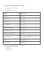
Specifications
GSM module
MTK program, GSM 900/1800/850/1900 dual-band or quad-band
Support the TCP protocol
GPS Chipset
JRC/SIRF III high sensitive chipset
GPS sensitivity
-164dB
C/A Code
1.023MHz chip rate
Channels
20 channel all-in-view tracking
GPS frequency
L1,1575.42MHz
GPS Position Accuracy
2.5 meters, CEP
Velocity Accuracy
0.1m/s
Time Accuracy
Synchronized to GPS time
Default datum
WGS-84
Hot start
1sec.,average
Warm start
30 seconds (average)
Cold Start
35 seconds (average)
Altitude Limit
18,000 meters (60,000feet) max.
Operating temperature
-20°C-65°C
Humidity
5%To 95% Non-condensing
Dimension
88mm×46mm×18mm
Voltage
12V-24V
Average Current When stand-by
<84mA
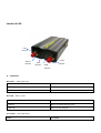
Interface & LED
GPS
Antenna
Battery
indicator
GPS
indicator
GSM
Antenna
GSM
indicator
LED Status
Blue LED: GSM signal status
Status
Description
Flashes every 8s
GSM network stand by
Flashes every 1 sec
No GSM network or SIM card not detected
Red LED: Battery status
Status
Description
Light ON
Battery in normal charging mode
Light OFF
Battery is fully charged
Green LED: GPS signal status
Status
Description
Light OFF
GPS signal not detected
Keeps flashing
Satellites found. GPS is receiving Data
Installation
Please read this manual before you carry hardware installation. If you have doubts, please contact your local
representations for help.
Package Contents:
a)
b)
c)
d)
e)
f)
1 x UDTTV02 GPS/GSM Vehicle Tracker
1 x Power cable
GPS Anetnna x 1
GSM Antenna x 1
1 x SOS button
Earphone & Microphone x 1
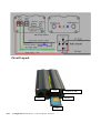
Basic Steps:
1. Eject SIM card holder, insert SIM card into SIM holder.
2. Connect GSM and GPS antenna
3. Connect the “5-cable- 6pin” connector to Port 1 (A 6 pin socket)
Port 1 – Color Representation for Cables:
Red
Black
Yellow
White
Green
:
:
:
:
:
(+) 12V/24V
Ground (-)
SOS button (-) Connect other side of switch to ground (-)
Engine immobilizer (-) (optional connection)
ACC detection. Battery in tracker will not be re-charged as soon as external power source is discontinued
Circuit Layout
USB
Earphone & MIC
SIM Eject
Port 1
SIM
Note: A 4-input Port beside “Port 1” is a reserved port, not used.
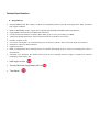
Quick start guideline
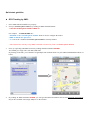
GPS Tracking by SMS:
1.
2.
Put in SIM card and install device properly.
Set up a controller phone number, by sending an SMS command format:
*controller mobile phone number*0000*1**.
For example, *12345678*0000*1**.
"12345678" is the controller phone number which is used to configure the tracker
“0000” is default user password
“1” is one of the 3 authorized controller phone numbers currently defined.
* The GPS Tracker will only accept SMS commands sent from any of the 3 controller phone numbers.
3.
Now, try requesting GPS URL location by sending an SMS command: 6680000
You should get a reply with a web link (URL link).
By clicking on the link, you will find a Google Maps GPS location shown on your GPRS enabled Mobile Phone, as
below:
4.
By sending an SMS command: 6660000, you will get GPS Data information such as GPS Longitude and Latitude.
Key in the coordinate into Google Maps to see the location.
GPS Real-Time Tracking by GPRS Setting:
1)
2)
Insert a GPRS enabled SIM card into the tracker.
Set up a controller phone number, by sending an SMS command format:
*controller mobile phone number*0000*1**.
For example, *12345678*0000*1**.
"12345678" is the controller phone number which is used to configure the tracker
“0000” is default user password
“1” is one of the 3 authorized controller phone numbers currently defined.
3)
4)
5)
6)
7)
8)
9)
Activate GPRS mode by sending an SMS command: 7100000
Define your Mobile Phone service provider’s APN, command #803#0000#APN Name#User name#password##.
Note: For the APN without user name and password, please use command #803#0000#APN Name##
Instruct Tracker to send GPS Data to Server Fixed IP, such as 61.144.222.116
By sending an SMS command: #804#0000#61.144.222.116#2332##
Setup user name, #801#0000#Your SIM Number (excluded country code)##
Setup upload interval while ACC ON, #805#0000#60#1##. 60 means GPS data is uploaded at every 60 seconds
interval.
Setup upload interval while ACC OFF, #809#0000#3600#1##. 3600 means GPS data is uploaded at 1 hour interval.
Log in www.udrivetrack.com (or wap.udrivetrack.com ) with valid “UserName” and “Password”
Useful SMS Commands:
The GPS Tracker is configured remotely by SMS commands. Each valid SMS command sent will get a reply message
with status report or acknowledgement.
Controller Phone Number
Format: * controller phone number 4-20 figures * user password (4 figures) *Sequence number (1-3) **
eg: *13900000000*0000*1**
Remarks: Controller Phone number is authorized to configure the tracker, maximum 3 controller phone numbers
are allowed. In the above example, the first controller number (marked as “1”) is 13900000000.
To Switch Tracking Mode to SMS Mode
Format:700+ user password (4 figures)
eg: 7000000
Reply: SET MODE OK, CURRENT MODE: SMS P2P
Remarks: When the tracker receives the SMS command with a valid password, it changes to
SMS Tracking mode.
Change User Password
Format: 777+new password (4 figures) +old password (4 figures)
eg: 77712340000
Reply: SET USER PASSWORD OK
Remarks: In the above example, instruction is given to change old password "0000" to new password "1234"
Power management (GPS to turn ON, OFF on with Vibration Sensor mode)
ON the GPS
Format: 222+user password (4 figures)
eg: 2220000
Reply: GPS ON OK
Remarks: When the tracker receives the instruction with a valid password, it switches the GPS to active mode.
OFF GPS
Format: 333+ user password (4 figures)
eg: 3330000
Reply: GPS OFF OK
Remarks: When the tracker receives the instruction with a valid password, it switches off the GPS.
Power-saving mode
The UDTTV02 has a built-in vibration sensor for power management. When the vibration sensor discovers that
there is no movement for 5 minutes, it can automatically turn GPS off, useful to preserve vehicle battery life.
Once the vibration sensor is triggered, the tracker will resume GPS function as usual.
Format: 100+ user password (4 figures)
eg:1000000
Reply: VIBRATION SENSOR ON OK
Remarks: When the tracker receives the instruction with a valid password, vibration sensor function is
activated.
Request
“Longitude and latitude”
by SMS
Format: 666+ user password (4 figures)
eg: 6660000
Reply: Location message as below
Data format:
Sample Message:
Lat: Latitude (+/-)
Lat:+22.54619
Long: Longitude (+/-)
Long: +114.12378
Speed: Speed KM/H
Speed: 0.00KM/H
Direction: Direction
Direction: 315.00
Date: Date YYYY-MM-DD
Date: 2008-04-25
Time: Time HH:MM:SS
Time: 16:39:45
BS: GSM Base Station information
BS: 25ee0dff
Fix: Location state (A/V)
Fix: A (A means received GPS signal, V means the low
GPS signal, inaccurate position)
ID: IMEI
ID: 353686009002030
STATE: Tracker Status
STATE: SMS
While GPS does not detect satellite signal, it replies SMS as below:
eg: ERROR GPS GPRMC FRAME DATA
BS: 27971054”
ID: 353686009002030
STATE: SMS
Request “Google Maps URL Location” by SMS
Format: 668+ user password (4 figures)
eg: 6690000
Reply: Location message in Google Maps URL link
Timer for SMS tracking
Activate timer tracking
Format: 4 xx + user password (4 figures)
eg: 4010000
Reply : TIMER START, REPEAT INTERVAK : X MINUTES
Remarks: The tracker would automatically sends location information to controller phone number at every X
minutes interval. Reporting time is either in minutes or hours. In the above example, the device
sends location information at every 1 minute interval with "STATE:TIMER".
Minimum value is 1 minute and maximum value is 120 minutes.
Stop timer tracking
Format: 400+user password
Reply: TIMER STOP
Alarm Alert by SMS commands:
Alert by SMS
Format: 150 + user password (4 figures)
eg: 1500000
Reply: SET VOICE CALL: OFF
Remarks: Activate device with Alarm Alert function (that is, Geo-fence, Panic button etc) by SMS.
Alert by both “Voice call and SMS”
Format: 151 + user password (4 figures)
eg: 1510000
Reply: SET VOICE CALL: ON
Remarks: Activate device with “Alarm Alert with Voice Call and SMS”. Voice Call is the factory default setting.
By Demand, GPS Location by Making Voice call
Make a call to the Tracker. After 2-5 rings, “G{S Location information” will be sent to the controller phone with
"STATE: SMS".
SOS button(
(Panic button)
When the SOS button is pressed (hold down for more than 3 seconds), it will send “GPS Location” information to
the controller phone number. Information sent includes "STATE: SOS". First of all, the tracker calls the first
controller phone number. If the call is not answered (mobile off, out of coverage or no response), it will call the
second number and then the third, until the call is answered.
Geo- Fence:
Setup Geo-fence Area
A geo-fence is defined by “latitude and longitude” base point of where it is and a permitted radius of travel from
that point. If the vehicle travels outside this area the tracker will make a telephone call to the mobile phone that set
the geo-fence as an alert. It will also send an SMS text including ‘STATE: OS’. While it returns to Geo-fence area, it
raise same alert with "State:RS". The tracker will repeat the above when the vehicle re-enters the geo-fenced area.
Command 1: Setup Geo-fence base point on certain Long and Lat.
Find the base point in Google Maps, you can obtain the current “longitude and latitude”
Now send the SMS command which includes the vehicles current location;
Format 1: 004+ user passwordE/Wddd.dddddN/Sdd.dddddRzzz.z
e.g: 0040000E11406.0024S2233.4230R1.0
Remarks: E-- east longitude (+) ; W-- west longitude (-); N-- north latitude (+); S-- south latitude (-).
In this example, it uses E and N
Command 2: Take Current Location as Geo-fence base point
Format: 005+user password+Rzzz.z
eg: 0050000R1.0
Reply: SET GEOFENCE OK
Remarks: In the example, it assumes current location as base point, with radius 1.0km as geo-fence area
Turn On/Off Geo-fence Alert
To turn the geo-fence on, send the text command: 211 (Function) + password
For example: 2110000
Reply: GEO-FENCE ON
Turn geo-fence off, send the text command: 210 (Function) + password
For example: 2100000
Reply: GEO-FENCE OFF
Remarks: Once the tracker moves out of the restricted area, it will send “GPs Location” information by SMS
to controller phone number, with information, STATE: RS
Battery low voltage alert
When the device detects internal battery with “low power”, it will send a SMS message to controller phone number
with “GPS Location” information wnd with information, STATE:LP.
Immobilizer
Immobilizing A Vehicle
a. Command format: 900 + user password
b. Confirm command format: 901 + user password
Remarks: When the tracker receives an instruction to immobilize a vehicle, it will reply with a message:
"Confirm Power OFF?"
You need to “confirm action” by replying with an SMS command: 901 + user password
Tow alarm
Activate tow alarm
Command: 008+user password+Rzzz.z ( Range from 0.1 – 999.9 KM )
Example : 0080000R0.1 ( Setting Tow alarm Radius Range 100 Meters )
Eg: 0080000R1.0
Reply: SET MOVE RADIUS OK
Description: After ACC Off, device record latest position data as base point, (the data will be collect in 3 minutes after
ACC off) . For the example above, hen vehicle move out 1.0KM radius from base point, device will send location data
message with STATE: ACC OS to controller phone. If device back to area within the radius, device send location message
with STATE: ACC RS. This function was activated in pre-setting, with report radius 0.5km.
Cancel tow alarm
Command: 009+user password
Eg: 0090000
Reply: MOVE DEFENGCE:OFF
Description: Device will stop raise tow alert.
Recover Mobilization
a. Turn power back command: 902 + user password
b. Confirm recovery command: 903 + user password
Remarks: When the tracker receive an instruction to put “power back”, it will reply with a message:
"Confirm Power ON?"
Tou need to “confirm action” by replying with an SMs command: 903 + user password
Power Cut Alert
Raise Alarm if External Power Source is Cut
Command: 011 + user password
eg: 0110000
Reply: DEFENCE ON
Remarks: When external power source is cut, it will call the controller phone number and send
location information message with STATE: DEF.
Keep Silent if External Power Source is Cut
Command: 010+user password
eg: 0100000
Reply: DEFENCE OFF
Remark: This will NOT trigger Alarm Alert when External Power source is Cut
Useful SMS Commands (Typically for Real-Time Monitoring, GPRS Mode):
Switch to GPRS mode
Format:710+ user password (4 figures)
eg:7100000
Reply: SET MODE OK,CURRENT MODE:GPRS
Remarks: When UDTTV02 tracker receives the SMS command with a valid password, it will automatically
upload GPS Data to the Server.
Defining Mobile Phone Operator APN (Access Point Name)
Format1:#803#user password#APN##
eg:#803#0000#CMNET##
Format 2:#803#user password#APN#APN user name#APN password ##
Reply: SET GPRS ACCOUNT OK
Remarks: Setup APN with Format 1 if no APN user name and password is required
Use Format 2 if APN user name and password are required
Note: The factory default APN is CMNET.
APN can consists of 3 to 35 alphabetic, numeric, dots (.) underscore (_) and connectors (-).
APN user name and user password consists of 3 to 20 the numeric and alphabetic.
Set up TCP/IP Server IP address and Port number
Format:#804#user password#fixed IP address # port ##
eg:#804#0000#220.165.9.225#2332##
Reply: SET SERVER IP AND PORT OK
Remarks: Setup Server IP location and Network Port for GPRS data transmission.
Start Upload GPS Location Information via GPRS
Format:#806#user password##
eg:#806#0000##
Reply:START GPRS UPLOAD
Remarks: Start Data Transmission to server.
Data Upload Interval (ACC ON /OFF)
Data upload interval while ACC ON:
Format:#805#user password# T #N#
eg:#805#0000#30#2##
Reply: SET GPS SAMPLING TIME AND QUANTITY OK
Remarks: In the above example, when ACC ON, the tracker collects position data every 30 seconds, uploads data to
server every 2 data collected (1 minutes once).
Data collection interval 'T': minimum 10 seconds, maximum 59999 seconds.
Data uploads to Server while N units of coordinate collected, minimum value is 1, maximum 50.
Upload interval while ACC Off:
Format:#809#user password# T#N ##
eg:#809#0000#1800#1##
Remarks: In the above example, when ACC OFF, the tracker collects position data every 1800 seconds,
uploads data to server every 1800 seconds (1 data collected).
Data collection interval 'T': minimum 10 seconds, maximum 59999 seconds.
Data uploads to server while N units of coordinate collected, minimum value is 1, maximum 50.
Note: If the device does not detect a GPRS/GSM network, “GPs Location” Information
will be saved in internal buffer, up to a 300 data can be saved.
Data logger Function:
Activate Data Logger Function
Format: #807#user password#X##
Eg: #807#0000#5##
Reply: SET SAMPLING OK
Remarks: In the above example, the device saves location data to internal memory at every 5 seconds interval.
When the device goes into power saving mode, it will stop record data.
The data logger is capable of saving up to 5000 “Location Information”.
Upload Data Captured by Data Logger to Server
Format: #808#user password#Upload data for previous X hours##
eg: #808#0000#24#
Reply: START UPLOAD 24H HISTORY RECORD
Remarks: Start uploading Data Captured 24 hours ago to Server, from now.
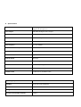
Appendix: Command List
Command
Sample
Description
Reply
*controller phone number 4-20 figures *
user password (4 figures) *Sequence
number (1-3) **
*13900000000*0000*1**
Set controller phone number
SET USER NUMBER 1 OK
700+Password
7000000
Start SMS tracking mode
710+Password
7100000
Start GPRS tracking mode
SET MODE OK, CURRENT MODE: SMS
P2P
SET MODE OK,CURRENT MODE:GPRS
004+PasswordE/Waaa.aaaaaN/Sbb.bbbbb
Rzzz.z
0040000E11406.0024S223
3.4230R1.0
Set geo-fence base point
SET GEOFENCE OK
005+PasswordRzzz.z
0050000R1.0
Set current location as geo-fence base
point
SET GEOFENCE OK
010+Password
100000
Not raise alert while power source being
cut off
DEFENCE OFF
011+Password
110000
Raise alert while power source being cut off
DEFENCE ON
100+Password
1000000
Power saving mode
VIBRATION SENSOR ON OK
150+Password
1500000
Raise alert by SMS
SET VOICE CALL: OFF
151+Password
1510000
Raise alert by voice call and SMS
SET VOICE CALL: ON
210+Password
2100000
Off geo-fence alert
GEO-FENCE OFF
211+Password
2110000
On geo-fence alert
GEO-FENCE ON
222+Password
2220000
On GPS receiver
GPS ON OK
333+Password
3330000
Off GPS receiver
GPS OFF OK
4xx+Password
4010000
Timer for SMS tracking
TIMER START, REPEAT INTERVAK : X
MINUTES
666+Password
6660000
Request location by SMS
Coordinate message
668+ Password
6680000
Request location by SMS with Google map
Link
Coordinate message
777+New Password+Old Password
77712340000
Change Password
SET USER PASSWORD OK
900+Password
9000000
Immobilize vehicle
Confirm Power OFF?
901+Password
9010000
Confirm immobilization
POWER OFF OK
902+Password
9020000
Recover mobilization
Confirm Power ON?
903+Password
9030000
Confirm recover mobilization
POWER ON OK
008+Paswword+Rzzz.z
0080000R100.0
Active tow alarm radius range 100 km
SET MOVE RADIUS OK
009+password
0090000
Cancel tow alarm
MOVE DEFENGCE:OFF
091+password
0910000
Raise alert while ACC ON/OFF
ACC STATE PROMPT:ON
090+password
0900000
Stop alert while ACC ON/OFF
ACC STATE PROMPT:OFF
#807#password#X##
#807#0000#10##
Start data logger function, record location
message every x seconds
SET SAMPLING OK
#808#0000#X##
#808#0000#24##
Upload data in data logger to server
START UPLOAD XH HISTORY RECORD
#803#Password#APN##
#803#0000#internet##
Set APN
SET GPRS ACCOUNT OK
#803#Password#APN#APN
username#APN pssword##
#803#0000#internet#guest
#guest##
Set APN user name
SET GPRS ACCOUNT OK
#804#Password#server's IP#port##
#804#0000#220.165.9.225
#2332##
Set GPRS tracking sever IP and port
SET SERVER IP AND PORT OK
#805#Password#Save GPS data every
“T” seconds#Upload data to server after
#805#0000#30#2##
Interval of GPS data upload to server while
engine started
SET GPS SAMPLING
QUANTITY OK
Start upload GPRS data
START GPRS UPLOAD
Interval of GPS data upload to server while
engine stopped
GPRS REPORT SAMPLING 2 STOP
TIME
"N" units message saved##
#806#Password##
#806#0000##
#809#Password#Save GPS data every“T” #809#0000#1800#1##
seconds#Upload data to server after
"N"units message saveded##
*RESET#password##。
*RESET#0000##
Reset to default setting
*RESTART#password##
*RESTART#0000##
Restart device
*GTAS#
*GTAS#
Read all setting
Setup details
AND