1
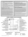
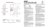
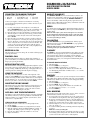
DIAMOND+3A/5A/10A
GUESTROOM TELEPHONE
USERS GUIDE
CONNECTING THE DIAMOND TELEPHONE
Included with the Diamond telephone are (one each):
• Base unit
• Coiled handset cord
• User guide
• Handset
• Clear plastic overlay
• Line cord
Contact your supplier or Teledex for information on ordering
custom designed and printed faceplates to enhance the look of your
Teledex telephone.
1) Located on the left side of the telephone is a modular jack
labeled TO HANDSET. Insert one end of the coiled handset cord
into this jack. It is inserted properly when you hear a click.
2) Insert the other end of the coiled handset cord into the handset.
3) Turn the telephone so the back panel is facing you. Insert either
end of the line cord into the jack on the back of the telephone
labeled TO TEL.
4) Insert the other end of the line cord into a telephone wall jack.
5) Once your telephone is connected, place the paper faceplate over
the keys. The plastic overlay slips into place by hooking the tabs
on the overlay into the recessed slots located on both sides. The
overlay is easiest to insert when the left or right side tabs are
inserted first, and the middle part of the overlay is slightly bowed
to allow for insertion of the other tabs.
RECEIVING A CALL
Lift the handset to answer incoming call. To end the call, hang up by
replacing the handset.
PLACING A CALL
Lift the handset. Listen for dial tone, dial the desired number, or
press an autodial key to automatically dial a number. To end the call,
hang up by replacing the handset.
MESSAGE WAITING LIGHT
The raised red lens is a message waiting light. Many telephone systems
turn on the red message waiting light to alert the user that there is a
message waiting. Additionally, the message waiting light will act as a
visual ring indicator, flashing when the telephone is ringing.
USING THE DATA PORT
The data port is a modular jack, located on the right side of the
telephone, labeled DATA. You can connect a fax machine, computer
modem, answering machine and other similar devices to the telephone
line through this port. To use the data port, insert the line cord from
the device you wish to connect into the jack labeled DATA.
ADJUSTING THE RING VOLUME
The telephone has two ring volume settings. To change the ring volume, locate the adjustment control on the back of the telephone
labeled RINGER LOW/HI. Slide the switch to the desired volume.
The ring volume can be changed at any time.
AUTO DIAL / ONE TOUCH FEATURE KEYS
Depending on your model, the telephone has up to ten (10) programmable
auto dial keys. These keys can be programmed to automatically dial
telephone numbers, or to activate telephone system features, when
connected to a compatible PBX.
STORING AUTO DIAL INFORMATION
The telephone must be connected to a working telephone line.
1) Lift the handset.
2) Press the STORE key and release it (see diagram for key location).
3) Enter the telephone number (including PAUSE as required - see
diagram.) The dialing sequence can be up to 15 digits long.
4) Press the auto dial key where the number is to be stored.
5) Replace the handset.
HANDSET VOLUME KEY
The HANDSET VOLUME key increases the handset volume to aid
in hard to hear environments. At the start of each call, the handset
volume is at a normal level. Pressing the HANDSET VOLUME key
increases the handset volume. Pressing the key again increases the
handset volume additionally. Pressing the key a third time returns the
handset volume to the normal level.
REDIAL
To redial the last telephone number dialed, lift the handset, listen for
dial tone, and press the REDIAL key. The telephone will dial the last
number dialed.
NOTE: Some PBX's require a pause after the first digit to access an outside
line. The redial function will automatically incorporate a pause if the dialed
number is 7 digits or more. The inserted pause will be of the same duration
as set in the pause timing (see below.)
CALL WAITING
The CALL WAITING key is a programmable auto dial key. Upon
shipment from the factory, the CALL WAITING key is programmed
with a 600 ms hookflash.
NOTE: Some PBX systems may require 'flash plus digits' to be dialed to access
call waiting. Contact your system administrator for details.
FLASH KEY
The FLASH key, when programmed behind an auto dial key, provides
a timed line interrupt typically used for accessing PBX/CO features
such as transfer and conference. The timing of the hookflash is
programmable, with the factory default timing set to 600 milliseconds.
Some PBXs may require you to change the hookflash timing from
the default 600ms.
TO CHANGE HOOKFLASH TIMING:
1)
2)
3)
4)
Lift the handset.
Press the STORE key (see diagram.)
Press the FLASH programming key (see diagram.)
Select 1 - 9 on the dial pad. The number selected will be the
new Flash timing in hundreds of milliseconds; ie: "3" = 300 ms.
5) Press the STORE key.
PAUSE KEY
The PAUSE key can be used to provide a timed pause between dialed
digits within an auto dial key. The timing of the pause is programmable,
with the factory default set to zero (0) seconds. To change pause timing:
1) Lift the handset.
2) Press the STORE key (see diagram.)
3) Press the PAUSE key (see diagram.)
4) Select 1 - 9 on the dial pad. The number selected will be the
new Pause timing in seconds; ie: "3" = seconds.
5) Press the STORE key.
WALL MOUNTING
The telephone can be wall mounted. It is easiest to do the conversion
when the handset and line cords are not connected.
1) Located on the front of the telephone, above the speaker grill, is
the wall/desk mount clip. Remove this clip by pushing upward.
2) Rotate clip one half turn (180 degrees) so the side with the protruding edge is towards the top. This edge will hold the handset.
3) Slide the clip downward into the slot until it snaps into place.
4) Turn the telephone over onto a non-abrasive surface so the back
side is up, facing you.
5) Locate the mounting bracket, and firmly push back and pull up
to remove.
NOTE: There are four (4) retaining tabs.
6) Rotate the mounting bracket one half turn (180 degrees) so that
the mounting eyelet is facing in the same direction as the mounting
eyelet located on the bottom surface of the telephone.
7) Insert the top two retaining tabs of the mounting brackets into
the mounting bracket slots located near the middle of the telephone,
then firmly push down and insert the retaining tabs on the
opposite side.
8) Connect a short modular line cord into the jack on the back of
the phone (labeled TO TEL). Route the line cord through the line
cord channel. Connect the other end of line cord to the phone
jack on the wall mounting plate.
9) Turn the telephone over, and slide the telephone onto the mount
ing posts on the wall plate in a downward direction. Both eyelets
should line up with the mounting posts. When properly installed,
the telephone will be stable and secure.
10) Complete wall mounting by installing the handset and handset cord.
This applies at any time during and after warranty. If unauthorized repair is performed, registration,
connection to the telephone lines and remainder of warranty period all become null and void.
7) This equipment is hearing aid compatible.
REQUIREMENTS OF PART 68 - FCC RULES
NOTICE: The Industry Canada label identifies certified equipment. This certification means that the
equipment meets certain telecommunications network protective operational and safety requirements
as prescribed in the appropriate Terminal Equipment Technical Requirements documents. The
department does not guarantee the equipment will operate to the users satisfaction. Before installing
this equipment, users should ensure that it is permissible to be connected to the facilities of the local
telecommunications company. The equipment must also be installed using an acceptable method of
connection. The customer should be aware that compliance with the above conditions may not prevent degradation of service in some situations. Repairs to certified equipment should be coordinated
by a representative designated by the supplier. Any repairs or alterations made by the user to this
equipment, or equipment malfunctions, may give the telecommunications company cause to request
the user to disconnect the equipment. Users should ensure for their own protection that the electrical
ground connections of the power utility, telephone lines, and internal metallic water pipe systems, if
present, are connected together. This precaustion may be particularly important in rural areas.
Caution: Users should not attempt to make such connections themselves, but should contact the
appropriate electric inspection authority or electrician, as appropriate.
This device has been granted a registration number by the Federal Communications Commission,
under Part 68 rules and regulations for direct connection to the telephone lines. In order to comply
with these FCC rules, the following instructions must be carefully read and applicable portions followed completely:
1) Direct connection to the telephone lines may be made only through the standard modular cord
furnished, to the utility installed jack. No connection may be made to party or coin phone lines.
On the bottom of the phone is a label that contains, among other information, the FCC Registration
Number and the Ringer Equivalence number (REN) for this equipment. If requested this information
must be provided to the telephone company. The USOC Jack for this equipment is RJ11C.
2) The telephone company, under certain circumstances, may temporarily discontinue and make
changes in facilities and services which may affect the operation of the users' equipment. However,
the user shall be given adequate notice in writing to allow the user to maintain uninterrupted service.
3) In certain circumstances, it may be necessary for the telephone company to request information
from you concerning the equipment which you have connected to your telephone line. Upon request
of the telephone company, provide the FCC registration number and the ringer equivalence number
of the equipment which is connected to your line; this information will be found on the device.
4) If any of your telephone equipment is not operating properly, you should immediately remove it
from the telephone line. It may cause harm to the telephone network.
5) If the telephone company notes a problem, they may temporarily discontinue service. When practical,
they will notify you in advance of disconnection. If advance notice is not feasible, the telephone company must; promptly notify you of such temporary discontinuance; afford the opportunity to correct
the condition; inform you of your rights to bring a complaint to the FCC under their rules.
6) Repairs to the device may be made only by the manufacturer or an authorized service agency.
REQUIREMENTS OF PART 15 - FCC RULES
NOTE: This equipment has been tested and found to comply with the limits for a Class B digital
device, pursuant to Part 15 of the FCC Rules. These limits are designed to provide reasonable protection against harmful interference in a residential installation. This equipment generates, uses, and
can radiate radio frequency energy and, if not installed and used in accordance with the instruction,
may cause harmful interference to radio communications. However, there is not a guarantee that
interference will not occur in a particular installation. If this equipment does cause harmful interference
to radio or television reception, which can be determined by turning the equipment off and on, the
user is encouraged to try to correct the interference by one or more of the following measures:
a) move the telephone away from the receiver. b) consult the dealer or an experienced radio/TV
technician for help. Any changes made by the user not approved by the manufacturer can void the
user's authorty to operate the telephone.
INDUSTRY OF CANADA REQUIREMENTS
The Ringer Equivalence Number (REN) of this device is Z.
NOTICE: The Ringer Equivalence Number (REN) assigned to each terminal device provides an indication of the maximum number of terminals allowed to be connected to a telephone interface. The
termination on an interface may consist of any combination of devices subject only to the requirement
that the sum of the Ringer Equivalence Numbers of all the devices does not exceed 5. This
telephone connects to the telephone network under the connecting arrangement code CA11A.
TELEDEX DIAMOND+3A/5A/10A DIAGRAM
DATA PORT
RING VOLUME
Adjusts the ringer volume
to low or high setting.
PAUSE KEY (hidden)
For programming of PAUSE duration.
See instructions for programming details.
HANDSET HOLDER
Used to temporarily hold the handset,
without hanging up the telephone,
when telephone is wall mounted.
STORE KEY (hidden)
Used in programming of number sequences.
See instructions for programming details.
HEARING AID COMPATIBLE HANDSET
FLASH PROGRAMMING KEY (hidden)
For programming of FLASH duration.
See instructions for programming details.
HANDSET RETAINING CLIP
This removable clip can be rotated 180
degrees to allow handset to stay on hook
when used in wall mount applications.
MESSAGE WAITING LIGHT
Signals that a message is waiting for retrieval.
See your system administrator for instructions
on retrieving messages.
HANDSET JACK
Modular jack for connecting handset to base.
REDIAL KEY
DIAL KEYS (DTMF PAD)
Automatically redials last number dialed.
For dialing phone numbers, and entering
numbers to be stored in auto dial keys.
CALL WAITING/FLASH KEY
Sends a hookswitch flash, to enable call waiting
or actuate other system features.
AUTO DIAL KEYS
For quick access to guest services.
Depending on model, your telephone may
have three, five, or ten auto dial keys. See
instructions for programming details.
FOR CUSTOMER SERVICE CALL:
1-800-783-8353
Part Number Coral 606-0482A00CL
Rev. A 8/02
HANDSET VOLUME KEY
Raises handset volume by repeatedly pressing.
Continues to cycle through volume levels with
each key-press.
CONTACTING TELEDEX
Teledex, LLC
6311 San Ignacio Avenue
San Jose, CA
95119
Telephone:
Fax:
email:
Internet:
(408) 363-3100
(408) 363-3136
[email protected]
www.teledex.com