1
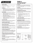
OPAL 1010S
GUESTROOM TELEPHONE
USERS GUIDE
Included with the Opal 1010S are (one each):
• Base unit
• Coiled handset cord
• User guide
• Handset
• Clear plastic overlay
• Line cord
TO ACTIVATE THE SPEAKERPHONE FROM HANDSET
MODE:
1) Press the SPEAKER key.
2) The red SPEAKER LED will indicate speakerphone selection.
3) Place the handset back into the cradle.
Contact your supplier or Teledex for information on ordering
custom designed and printed faceplates to enhance the look of your
Teledex telephone.
USING THE HOLD KEY
CONNECTING THE OPAL 1010S
1) Located on the left side of the Opal 1010S (as the phone is facing you) is a modular jack. Insert one end of the coiled handset
cord into this jack (you should hear the coil cord click when
properly inserted).
2) Insert the other end of the coiled handset cord into the modular
jack on the handset.
3) Turn the telephone so the back panel is facing you. Insert either
end of the line cord into the jack on the back of the telephone
labeled LINE.
4) Insert the other end of the line cord into a telephone wall outlet
jack.
5) Once your telephone is connected, remove the plastic overlay
and place the paper faceplate over the keys. Replace the plastic
overlay by hooking the tabs on the overlay into the recessed
slots located on both sides. The overlay is easiest to insert when;
the left or right side tabs are inserted first, and the middle of the
overlay is slightly bowed to allow for insertion of the other tabs.
PLACING A CALL
USING THE HANDSET:
1) Lift the handset.
2) Listen for dial tone, dial the desired number, or press an AUTO
DIAL key to automatically dial a number.
3) To end the call, hang up by placing the handset back in the cradle.
USING THE SPEAKERPHONE:
1) With the handset in the cradle, press the SPEAKER key. The
Opal will engage the open line.
NOTE: The red SPEAKER LED will indicate that the speakerphone is active.
2) Listen for dial tone. Dial the desired number, or press an AUTO
DIAL key to automatically dial a number.
3) To end call the call press the SPEAKER key again.
RECEIVING A CALL
An audible ring and flickering red LED indicate an inbound call.
USING THE HANDSET:
1) Lift the handset. The Opal will select the ringing line.
2) To end the call hang up the handset.
USING THE SPEAKERPHONE:
With the handset in the cradle, press the SPEAKER key. The Opal
will select the ringing line and answer with the speakerphone active.
Note: The red SPEAKER LED will indicate that the speakerphone is
active.
ADJUSTING SPEAKERPHONE VOLUME
Locate the slide switch (labeled SPKR VOL) on the right side of the
telephone. To increase speaker volume, slide the switch towards the
back of the telephone. To decrease speaker volume, slide the switch
towards the front of the telephone.
ADJUSTING THE RING VOLUME
Locate the adjustment control on the back of the telephone labeled
RINGER LOW/HI (see diagram). Slide the switch to the desired LOW
or HI ring volume.
SPEAKERPHONE TIPS
TO ACTIVATE THE HANDSET FROM SPEAKERPHONE
MODE:
1) Lift the handset from the cradle.
2) The red SPEAKER LED will go out.
The HOLD key places the call on hold locally at the Opal telephone.
TO PLACE A CALL ON HOLD
1) With a call active press the red HOLD key.
2) The red line LED will change to a slow blink indicating the call
is on hold.
TO REMOVE A CALL FROM HOLD
1) Lift the handset from the cradel. This will remove the call from
hold making the call active on the handset.
- OR With the handset in the cradle, press the SPEAKERPHONE key.
This will remove the call from hold making the call activate the
speakerphone.
2) The red line LED will return to steady in-use condition.
TO CHANGE PHONES AFTER PLACING A CALL ON HOLD
1) Place the call on HOLD on the Opal.
2) Pickup the call at another telephone. The Opal will detect the
pickup and remove the hold condition at the original Opal.
TO MUTE SPEAKERPHONE AND HANDSET CALLS
1) Press the MUTE key, the red LED below the MUTE key will light.
The party on the other end will not hear you when the MUTE
key is depressed.
2) Press the MUTE key again to turn off the mute feature, the MUTE
LED will go out.
REDIAL
TO REDIAL THE LAST TELEPHONE NUMBER DIALED:
1) Lift the handset from the cradle, or press the SPEAKERPHONE
key.
2) Press the REDIAL key.
NOTE: Some PBX’s require a pause after the first digit to access an
outside line. The REDIAL function will automatically insert a pause if
the dialed number is 7 digits or more. The inserted pause will be of the
same duration as set in the pause timing.
FLASH KEY
The Flash key, when programmed behind an autodial key provides a
timed line interrupt typically used for accessing PBX/CO features like
transfer and conference. The timing of the hookflash is programmable
with the factory default timing set to 600 milliseconds. Some PBX’s
may require you to change the hookflash timing from the default to
600ms.
To change the hookflash timing;
1) Lift the handset.
2) Press the STORE key (see diagram for key location).
3) Press the FLASH key (see diagram for key location).
4) Select 1 - 9 on the DTMF pad. The number selected will be the
new flash timing in milliseconds (ie: “3” = 300 milliseconds).
5) Press the STORE key.
ADJUSTING THE HANDSET VOLUME
The HANDSET VOLUME key has three levels. When the handset is
first lifted, the handset volume is NORMAL.
Locate the HANDSET VOLUME key below the keypad. Press the key
once and the volume level will increase one level (to MEDIUM volume). Press the key once more and the volume level will increase an
additional level (to HIGH volume). To return the handset volume to
NORMAL, press the handset volume key again. The handset volume
will always return to NORMAL when the handset is returned to the
cradle.
PAUSE KEY
The Pause key, when programmed behind an autodial key can be used
to provide a timed pause between dialed digits within an autodial key.
The timing of the pause is programmable with the factory default set
to zero (0) seconds.
To change the pause timing;
1) Lift the handset.
2) Press the STORE key (see diagram for key location).
3) Press the PAUSE key (see diagram for key location).
4) Select 1 - 9 on the DTMF pad. The number selected will be the new
pause timing in seconds (ie: “3” = 3 seconds).
5) Press the STORE key.
AUTO DIAL KEYS
The Opal 1010S has ten (10) programmable AUTO DIAL keys.
These keys can be programmed to automatically dial telephone numbers, or activate telephone system features.
PROGRAMMING AUTO DIAL KEYS:
The telephone must be connected to a telephone line.
1) Remove the plastic overlay.
2) Lift the handset from the cradle or press the SPEAKERPHONE key.
3) Press the recessed STORE key and release it. (Please see diagram
for key location).
4) Enter the telephone number including PAUSE* as required. The
sequence can be up to 15 digits.
5) Press the AUTO DIAL key where the number is to be stored.
6) Place the handset back in the cradle or press the SPEAKERPHONE key to disconnect.
RMA PROCEDURES
The following procedure should be followed with all Teledex
telephone products prior to sending the telephone to the factory
for repair.
1) Please perform the tests listed below:
a. Test the telephone on a different telephone jack.
b. Test telephone with a different line cord.
c. Test with a different handset cord (coiled cord).
d. For two line products, please ensure that one of the line
buttons is pressed (if both line buttons are in the UP position,
the telephone will not operate).
2) If the steps listed above do not provide a remedy for the suspect
telephone, please place a tag on the individual telephone
describing the defect. Next, call the Teledex Repair Department
at 1 (800) 875-8539 for an RMA number. You must have an
RMA number to return products to Teledex.
3) Kindly note: An RMA number is unique to each return
shipment. Do not duplicate this number on any future shipments.
SHIPPING INSTRUCTIONS:
Please print the RMA number clearly on the outside of your shipping
carton(s). Please ship to the following address:
Teledex LLC / RMA#___________
6311 San Ignacio Avenue
San Jose, CA 95119
FREIGHT CHARGES:
The Customer is responsible for shipping products for repair to
Teledex. After repair, Teledex will return telephone products to the
Customer freight prepaid in the same manner in which is was sent
(i.e. Freight sent to Teledex UPS Blue, will be returned via 2 day shipping).
**Please note: When telephones are returned for repair due to misuse
(i.e. liquid spills, abuse, or Customer modification - warranty label
broken), the Customer will be charged the standard repair fee, regardless of warranty status.
CONVERTING FROM DESK TO WALL MOUNT
The Opal 1010S telephone can be changed for wall mount applications. The conversion is easiest when the handset and line cords are
not connected.
1) Located on the front of the telephone above the speaker grill is
the wall/desk mount clip. Remove this clip by firmly pushing
upward (towards the hookswitch).
2) Rotate the clip a half turn (180 degrees) so that the side with the
protruding edge is towards the top. This edge will hold the
handset. (Closest to the hookswitch.)
3) Return the clip to its original location by pushing the clip dow
wards, until it stops (snaps into place).
4) Turn the Opal 1010S over so that the back side is up, facing you
(A non abrasive surface is suggested to prevent scratching).
5) Locate and remove the mounting bracket, firmly push back and
pull up to remove two of the four retaining tabs.
6) Rotate the mounting bracket a half turn (180 degrees) so that
the mounting eyelet is facing in the same direction as the other
mounting eyelet located on the telephone.
7) Insert the top two retaining tabs of the mounting brackets into
the mounting bracket slots (located near the middle of the telephone). Then firmly push down to insert the retaining tabs on
the opposite side of the mounting bracket.
8) Connect a short modular line cord into the jack on the back of
the phone (labeled TO TEL). Route the line cord through the line
cord channel. Connect the other end of line cord to the phone
jack on the wall mounting plate.
9) Turn the telephone over, and slide the Opal 1010S down onto
the wall plate mounting posts. Both eyelets should line up with
the mounting posts (When properly installed the telephone will
be stable and secure).
10) Complete the wall mounting by installing the handset and hand
set cord.
REQUIREMENTS OF PART 68 - FCC RULES
This device has been granted a registration number by the Federal Communications Commission,
under Part 68 rules and regulations for direct connection to the telephone lines. In order to comply
with these FCC rules, the following instructions must be carefully read and applicable portions followed completely:
1. Direct connection to the telephone lines may be made only through the standard modular cord furnished, to the utility installed jack. No connection may be made to party or coin phone lines. On
the bottom of the phone is a label that contains among other information, the FCC Registration
Number and the Ringer Equivalence number (REN) for this equipment. If requested this information must be provided to the telephone company. The USOC Jack for this equipment is RJ11C.
2. The telephone company, under certain circumstances, may temporarily discontinue and make
changes in facilities and services which may affect the operation of the users' equipment: however,
the user shall be given adequate notice in writing to allow the user to maintain uninterrupted service.
3. In certain circumstances, it may be necessary for the telephone company to request information
from you concerning the equipment which you have connected to your telephone line. Upon
request of the telephone company, provide the FCC registration number and the ringer equivalence number of the equipment which is connected to your line; this information will be found on
the device.
4. If any of your telephone equipment is not operating properly, you should immediately remove it
from the telephone line. It may cause harm to the telephone network.
5. If the telephone company notes a problem, they may temporarily discontinue service. When practical, they will notify you in advance disconnection. If advance notice is not feasible, the telephone
company must; promptly notify you of such temporary discontinuance; afford the opportunity to
correct the condition; inform you of your rights to bring a complaint to the FCC under their rules.
6. Repairs to the device may be made only by the manufacturer or an authorized service agency.
This applies at any time during and after warranty. If unauthorized repair is performed, registration,
connection to the telephone lines and remainder of warranty period all become null and void.
7. This equipment is hearing aid compatible.
8. This telephone must be connected behind a PBX.
REQUIREMENTS OF PART 15 - FCC RULES
NOTE: This equipment has been tested and found to comply with the limits for a Class B digital
device, pursuant to Part 15 of the FCC Rules. These limits are designed to provide reasonable protection against harmful interference in a residential installation. This equipment generates, uses, and
can radiate radio frequency energy and, if not installed and used in accordance with the instruction,
may cause harmful interference to radio communications. However, there is not a guarantee that
interference will not occur in a particular installation. If this equipment does cause harmful interference to radio or television reception, which can be determined by turning the equipment off and on,
the user is encouraged to try to correct the interference by one or more of the following measures:
Move the telephone away from the receiver. -Consult the dealer or an experienced radio/TV technician for help. Any changes made by the user not approved by the manufacturer can void the user's
authority to operate the telephone.
INDUSTRY OF CANADA REQUIREMENTS
NOTICE: The Industry Canada label identifies certified equipment. This certification means that the
equipment meets certain telecommunications network protective operational and safety requirements
as prescribed in the appropriate Terminal Equipment Technical Requirements documents. The
department does not guarantee the equipment will operate to the users satisfaction.
Before installing this equipment, users should ensure that it is permissible to be connected to the
facilities of the local telecommunications company. The equipment must also be installed using an
acceptable method of connection.
The customer should be aware that compliance with the above conditions may not prevent degradation of service in some situations.
Repairs to certified equipment should be coordinated by a representative designated by the supplier.
Any repairs or alterations made by the user to this equipment, or equipment malfunctions, may give
the telecommunications company cause to request the user to disconnect the equipment.
Users should ensure for their own protection that the electrical ground connections of the power utility, telephone lines, and internal metallic water pipe systems, if present, are connected together. This
precaustion may be particularly important in rural areas.
Caution: Users should not attempt to make such connections themselves, but should contact the
appropriate electric inspection authority or electrician, as appropriate.
The Ringer Equivalence Number (REN) of this device is Z.
Notice: The Ringer Equivalence Number (REN) assigned to each terminal device provides an indication of the maximum number of terminals allowed to be connected to a telephone interface. The termination on an interface may consist of any combination of devices subject only to the requirement
that the sum of the Ringer Equivalence Numbers of all the devices does not exceed 5. This telephone connects to the telephone network under the connecting arrangement code CA11A.
IMPORTANT SAFETY INSTRUCTIONS
WHEN USING YOUR TELEPHONE EQUIPMENT, BASIC SAFETY PRECAUTIONS SHOULD
ALWAYS BE FOLLOWED TO REDUCE THE RISK OF FIRE, ELECTRIC SHOCK AND INJURY TO
PERSONS. INCLUDING THE FOLLOWING:
1. READ AND UNDERSTAND ALL INSTRUCTIONS.
2. FOLLOW ALL WARNINGS AND INSTRUCTIONS MARKED ON THE PRODUCT.
3. UNPLUG THE PRODUCT FROM THE WALL OUTLET BEFORE CLEANING. DO NOT USE LI
UID CLEANER OR AEROSOL CLEANERS. USE A DAMP CLOTH FOR CLEANING.
4. DO NOT USE THIS PRODUCT NEAR WATER FOR EXAMPLE NEAR A BATHTUB, WASH
BOWL, KITCHEN SINK OR LAUNDRY TUB, IN A WET BASEMENT, OR NEAR A SWIMMING
POOL.
5. DO NOT PLACE THIS PRODUCT ON AN UNSTABLE CART, STAND OR TABLE. THE PRODUCT MAY FALL, CAUSING SERIOUS DAMAGE TO THE PRODUCT.
6. SLOTS AND OPENINGS IN THE CABINET AND THE BACK OF BOTTOM ARE PROVIDED
FOR VENTILATION, TO PROTECT IT FROM OVERHEATING, THESE OPENINGS MUST
NOT BE BLOCKED OR COVERED. THE OPENINGS SHOULD NEVER BE BLOCKED BY
PLACING THE PRODUCT ON THE BED, SOFA, RUG OR ANY OTHER SIMILAR SURFACE.
THIS PRODUCT SHOULD NEVER BE PLACED NEAR OR OVER A RADIATOR OR HEAT
REGISTER. THIS PRODUCT SHOULD NOT BE PLACED IN A BUILT-IN INSTALLATION
UNLESS PROPER VENTILATION IS PROVIDED.
7. NEVER PUSH OBJECTS OF ANY KIND INTO THIS PRODUCT THROUGH CABINET SLOTS
AS THEY MAY TOUCH DANGEROUS VOLTAGE POINTS OR SHORT OUT PARTS THAT
COULD RESULT IN A RISK OF FIRE OR ELECTRIC SHOCK. NEVER SPILL LIQUID OF ANY
KIND ON THE PRODUCT.
8. TO REDUCE THE RISK OF ELECTRIC SHOCK DO NOT DISASSEMBLE THIS PRODUCT
BUT TAKE IT TO A QUALIFIED SERVICEMEN WHEN SOME SERVICE OR REPAIR WORK IS
REQUIRED. OPENING OR REMOVING COVERS MAY EXPOSE YOU TO DANGEROUS
VOLTAGES OR OTHER RISKS. INCORRECT REASSEMBLE CAN CAUSE ELECTRIC
SHOCK WHEN THE APPLIANCE IS SUBSEQUENTLY USED.
9. UNPLUG THIS PRODUCT FROM THE WALL OUTLET AND REFER SERVICING TO QUAL
FIED SERVICE PERSONNEL UNDER THE FOLLOWING CONDITIONS.
· WHEN THE POWER SUPPLY CORD OR PLUG IS DAMAGED OR FRAYED
· IF LIQUID HAS BEEN SPILLED INTO THE PRODUCT.
· IF THE PRODUCT HAS BEEN EXPOSED TO RAIN OR WATER.
· IF THE PRODUCT DOES NOT OPERATE NORMALLY BY FOLLOWING THE OPERATING
INSTRUCTIONS. ADJUST ONLY THOSE CONTROLS THAT ARE COVERED BY THE
OPERATING INSTRUCTIONS BECAUSE IMPROPER ADJUSTMENT OF OTHER CONTROLS MAY RESULT IN DAMAGE AND WILL OFTEN REQUIRE EXTENSIVE WORK BY A
QUALIFIED TECHNICIAN TO RESTORE THE PRODUCT TO NORMAL OPERATION.
· IF THE PRODUCT HAS BEEN DROPPED OR THE CABINET HAS BEEN DAMAGED.
· IF THE PRODUCT EXHIBIT A DISTINCT CHANGE IN PERFORMANCE.
10. AVOID USING A TELEPHONE (OTHER THAN A CORDLESS TYPE) DURING AN ELECTRICAL STORM. THERE MAY BE A REMOTE RISK OF ELECTRIC SHOCK FROM LIGHTING.
11. DO NOT USE THE TELEPHONE TO REPORT A GAS LEAK IN THE VICINITY OF THE LEAK.
SAVE THESE INSTRUCTIONS
TELEDEX OPAL 1010S DIAGRAM
MESSAGE WAITING LIGHT
RING VOLUME
Signals that a message is waiting for retrieval.
See your system administrator for instructions
on retrieving messages.
Adjusts the ringer volume
to Low or High setting.
HANDSET HOLDER
HANDSET JACK
Used to temporarily hold the handset,
without hanging up the telephone,
when telephone is wall mounted.
Modular jack for connecting handset to base.
DATA PORT
STORE KEY (hidden)
HEARING AID COMPATIBLE HANDSET
Used in programming of number sequences.
See instructions for programming details.
FLASH KEY (hidden)
For programming of FLASH duration.
AUTO DIAL KEYS 1-5
For easy, one-touch dialing of guest services or
PBX features. Programmed during installation.
DIAL KEYS (DTMF PAD)
For dialing phone numbers, and entering
numbers to be stored in auto dial keys.
AUTO DIAL KEYS 6-10
For easy, one-touch dialing of guest services or
PBX features. Programmed during installation.
HOLD KEY
SPEAKERPHONE KEY
REDIAL KEY
MUTE KEY
To automatically redial Changes handset volume by
pressing repeatedly.
last number dialed
FOR CUSTOMER SERVICE CALL
Part Number 606-2660-00A
HANDSET VOLUME KEY
1-800-783-8353
Teledex, LLC
6311 San Ignacio Avenue
San Jose, CA
95119
Telephone:
Fax:
email:
Internet:
(408) 363-3100
(408) 363-3136
[email protected]
www.teledex.com