1
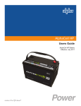
AlphaCell™ GelCell Series
AlphaCellTM GelCell Battery Users Guide
Storage, Maintenance, and Deployment
Effective: April, 2013
Alpha Technologies
Power
Alpha Technologies
®
AlphaCellTM GelCell Battery Users Guide
Storage, Maintenance and Deployment
745-680-C0-002, Rev. B1
Effective Date: April 2013
Copyright© 2013
Alpha Technologies, Inc.
member of The
GroupTM
NOTE:
Photographs contained in this manual are for illustrative purposes only. These photographs may not match
your installation.
NOTE:
Operator is cautioned to review the drawings and illustrations contained in this manual before proceeding. If
there are questions regarding the safe operation of this product, please contact Alpha Technologies or your
nearest Alpha representative.
NOTE:
Alpha shall not be held liable for any damage or injury involving its enclosures, power supplies, generators,
batteries, or other hardware if used or operated in any manner or subject to any condition not consistent with
its intended purpose, or is installed or operated in an unapproved manner, or improperly maintained.
Contacting Alpha Technologies: www.alpha.com
or
For general USA sales information and customer service (7 AM to 5 PM, Pacific Time), call
1 800 863 3930
For complete technical support in the USA, call
7 AM to 5 PM, Pacific Time or 24/7 emergency support
1 800 863 3364
For Sales information and Technical Support in Canada, call
1 800 667 8743
745-680-C0-002, Rev. B1
3
Table of Contents
Safety Notes........................................................................................................................................................ 6
Battery Maintenance Guidelines......................................................................................................................... 7
Recycling and Disposal Instructions.................................................................................................................... 7
Storage................................................................................................................................................................ 8
Electrical Safety................................................................................................................................................... 8
Chemical and Mechanical Safety........................................................................................................................ 9
1.0Introduction........................................................................................................................................... 10
1.1
2.0
Preparing for Maintenance................................................................................................................... 12
2.1
3.0
Description...............................................................................................................................11
Required Tools and Equipment............................................................................................... 12
Periodic Maintenance Tasks and Schedule.......................................................................................... 13
3.1
Monthly Remote Status Monitoring......................................................................................... 13
3.2
Quarterly Preventive Maintenance.......................................................................................... 14
3.3AlphaCellTM Battery Maintenance Log..................................................................................... 16
3.4
Battery Evaluation Procedures................................................................................................ 18
3.5
Battery Refurbishment Plan..................................................................................................... 19
4.0
Battery System Float Charging............................................................................................................. 20
4.1
Alpha Power Supply Charging Profile..................................................................................... 21
5.0
Battery Symptoms and Solutions......................................................................................................... 22
6.0
Battery Parameters by Model Number................................................................................................. 25
7.0
Warranty and Return Information......................................................................................................... 27
7.1AlphaCellTM Limited Warranty.................................................................................................. 27
7.2
4
Battery Maintenance Report for Return Authorizations........................................................... 29
745-680-C0-002, Rev.B1
Figures and Tables
Fig. 1, Capacity vs Storage Time............................................................................................................ 8
Fig. 2, Series Connected String of Batteries.........................................................................................11
Fig. 3, Parallel String of Batteries..........................................................................................................11
Fig. 4, Flow Chart, Monthly Status Monitoring...................................................................................... 13
Fig. 5, Flow Chart, Quarterly Preventive Maintenance......................................................................... 14
Fig. 6 Flow Chart for Battery Refurbishment Plan................................................................................ 19
Fig. 7, Charger Modes.......................................................................................................................... 21
Table 1, Conductance values, new vs. suspect batteries..................................................................... 18
Table 2, Battery Symptoms and Solutions............................................................................................ 22
Table 3, Battery Parameters, Current Models (threaded insert terminals)........................................... 25
Table 4, Battery Parameters, Legacy Models (threaded insert terminals)............................................ 26
Table 5, Battery Parameters, Legacy Models, (Lead flag insert terminals).......................................... 26
Table 6, Warranty Periods for AlphaCellTM batteries............................................................................. 28
745-680-C0-002, Rev. B1
5
Safety Notes
Review the drawings and illustrations contained in this manual before proceeding. If there are any questions
regarding the safe installation or operation of the system, contact Alpha Technologies or the nearest Alpha
representative. Save this document for future reference.
To reduce the risk of injury or death, and to ensure the continued safe operation of this product, the following
symbols have been placed throughout this manual. Where these symbols appear, use extra care and
attention.
ATTENTION:
The use of ATTENTION indicates specific regulatory/code requirements that may affect the placement of
equipment and installation procedures.
NOTE:
A NOTE provides additional information to help complete a specific task or procedure.
CAUTION!
The use of CAUTION indicates safety information intended to PREVENT DAMAGE to material or
equipment.
WARNING!
A WARNING presents safety information to PREVENT INJURY OR DEATH to the
technician or user.
6
745-680-C0-002, Rev.B1
WARNING!
Lead-acid batteries contain dangerous voltages, currents, and corrosive material. Battery
installation, maintenance, service, and replacement must only be performed by authorized
personnel.
Battery Maintenance Guidelines
•
For optimal performance, inspect batteries every 3 months for:
Signs of battery cracking, leaking or swelling. The battery should be replaced immediately
by authorized personnel using a battery of the identical type and rating (match conductance,
voltages, and date codes as specified in this document).
Signs of battery cable damage. Battery cable should be replaced immediately by
authorized personnel using replacement parts specified by vendor.
Loose battery connection hardware. Refer to documentation for the correct torque and
connection hardware for the application.
•
Do not attempt to remove the vents (valves) from the AlphaCell GelCell battery or add water. This is a
safety hazard and voids the warranty.
•
Apply no-ox grease on all exposed connections.
•
When necessary, clean up any spilled electrolyte in accordance with all federal, state, and local
regulations or codes.
•
Follow approved storage instructions.
•
Always replace batteries with those of an identical type and rating. Never install untested batteries.
•
Do not charge batteries in a sealed container. Each individual battery should have at least 1/2 inch of
space between it and all surrounding surfaces to allow for convection cooling.
•
All battery compartments must have adequate ventilation to prevent an accumulation of potentially
dangerous gas. Never place batteries in a sealed enclosure. Extreme caution should be used when
maintaining and collecting data on the battery system.
Recycling and Disposal Instructions
•
Spent or damaged batteries are considered environmentally unsafe as they contain lead and dilute
sulfuric acid. They should not be "thrown away" with common refuse.
•
Always recycle used batteries in accordance with federal, state, provincial, and local regulations. The
Alpha Group provides recycling services. Call 800 863 3930 or contact your local Alpha representative.
745-680-C0-002, Rev. B1
7
Important Storage Practices
All lead acid batteries experience self-discharge while in open circuit storage. This causes circuit
voltage and capacity to decrease (see Fig.1). This is especially true if the batteries are stored for
long periods of time at higher temperatures. Storage of the batteries in the shaded area of Figure
1 is not recommended, as higher temperatures combined with longer periods of storage will result
in diminished residual capacity — hence a shorter battery lifespan.
NOTE:
The product warranty is void if the batteries are not stored and recharged in accordance with these guidelines.
During storage please note:
•
The self-discharge rate is related to ambient temperature. The lower the temperature, the less
the discharge. Batteries should be stored in a clean, ventilated, and dry location with an ambient
temperature of 32ºF to 68ºF (0ºC to 20ºC).
•
It is important to track open circuit voltage which is related to the density of the electrolyte. If
the open circuit voltage is lower than 12.6V or the batteries have been stored beyond the limits
shown in Figure 1, the batteries should be charged to avoid damage caused by self-discharge.
•
All batteries should be fully charged before storage. Record the storage date and next
supplemental charge date in a maintenance record and on the battery.
•
Upon battery deployment, verify all batteries within each string measure in the range of
+/- 0.3Vdc of the string average.
Residual Capacity (%)
32ºF (0ºC)
50ºF (10ºC
)
10
4
ºF (
40º
C)
68ºF (2
0
86ºF
(30
ºC)
ºC)
Storage Time (Months)
Fig. 1, Capacity vs. Storage Time
Electrical Safety
8
•
Lethal voltages are present within the power supply and electrical enclosures. Never assume that
an electrical connection or conductor is not energized. Check circuits with a volt meter prior to any
installation or removal procedure.
•
Observe circuit polarities.
•
Always use the buddy system when working under hazardous conditions.
•
Ensure no liquids or wet clothes contact internal components.
•
Hazardous electrically live parts inside this unit are energized from batteries even when the AC input
power is disconnected.
•
Use an insulated blanket to cover exposed portions of the battery system when performing extended
maintenance that could result in personal or equipment contact with the energized conductors.
•
Certain types of rectifier circuits used in charging the battery may not include a line isolating transformer.
In these cases extreme caution should be used when maintaining and collecting data on the battery
system.
745-680-C0-002, Rev.B1
WARNING!
Chemical Hazards
Any gelled or liquid emissions from a valve-regulated lead-acid (VRLA) battery contains dilute sulfuric acid,
which is harmful to the skin and eyes. Emissions are electrolytic and are electrically conductive and corrosive.
To avoid injury:
•
Servicing and connection of batteries shall be performed by, or under the direct supervision of, personnel
knowledgeable of batteries and the required safety precautions.
•
Always wear eye protection, rubber gloves, and a protective vest when working near batteries. To avoid
battery contact, remove all metallic objects, (such as rings or watches), from your person.
•
Batteries produce explosive gases. Keep all open flames and sparks away from batteries.
•
Use tools with insulated handles, do not rest any tools on top of batteries.
•
Batteries contain or emit chemicals known to the State of California to cause cancer and birth defects
or other reproductive harm. Battery post terminals and related accessories contain lead and lead
compounds. Wash hands after handling (California Proposition 65).
•
If any battery emission contacts the skin, wash immediately and thoroughly with water. Follow your
company’s approved chemical exposure procedures.
•
Neutralize any spilled battery emission with the special solution contained in an approved spill kit or with
a solution of one pound (454g) bicarbonate of soda to one gallon (3.8l) of water. Report a chemical spill
using your company’s spill reporting structure and seek medical attention if necessary.
•
Always replace batteries with those of an identical type and rating (match conductance, voltages, and
date codes as specified in this document).
•
Never install old or untested batteries.
•
Prior to handling the batteries, touch a grounded metal object to dissipate any static charge that may have
developed on your body.
•
Use special caution when connecting or adjusting battery cabling. An improperly or unconnected battery
cable can make contact with an unintended surface that can result in arcing, fire, or a possible explosion.
•
A battery showing signs of cracking, leaking, or swelling should be replaced immediately by authorized
personnel using a battery of identical type and rating.
Mechanical Safety
•
Keep hands and tools clear of fans.
•
Fans are thermostatically controlled and will turn on automatically.
•
Power supplies can reach extreme temperatures under load.
•
Use caution around sheet metal components, especially sharp edges.
•
Depending on the model, batteries can weigh anywhere from 25 to 100 pounds (11kg to 45kg). Exercise
care when handling and moving batteries. Use proper handling equipment.
745-680-C0-002, Rev. B1
9
1.0Introduction
The purpose of this guide is to provide the user with the necessary information to maintain batteries in storage
and deploy batteries in Alpha Powering systems, as well as perform battery testing, install replacements and
recycling.
This manual guides you through periodic maintenance checks and troubleshooting of the AlphaCell GelCell
batteries of 50 through 107 ampere hours capacity.
Adherence to the procedures and practices detailed in this guide will not only insure the battery operates per
specifications, but also provides the proper backup for the Alpha Powering system in which it is installed.
To achieve these goals, this guide will address the following topics:
• The storage and maintenance of new battery inventory.
• Deployment of AlphaCell batteries into Alpha Power systems.
• Proper preventiative maintenance practices for AlphaCell batteries.
• Replacement and recycling of AlphaCell batteries.
• Warehousing, testing, and redeployment of reuseable AlphaCell assets.
• How to keep proper maintenance records for troubleshooting and/or Warranty claims.
10
745-680-C0-002, Rev.B1
1.1Description
The AlphaCell GelCell battery is a lead acid battery that facilitates an oxygen recombination
cycle. The net result, under normal conditions, is minimal gas emission and water loss from
the electrolyte. The electrolyte is immobilized in either a gel form or is absorbed within an
absorbent separator between the plates. Consequently, there is no requirement to add water
to the cells or to measure the electrolyte specific gravity.
A 12V battery is made up of six 2V cells internally connected to provide 12 volts.
The battery system is a group of 12V batteries connected in a series string to provide a
higher voltage system. In Fig. 2, three of the nominal 12V batteries are connected in series to
provide an 18 cell system with a nominal voltage of 36V.
to power supply: red
(+), black (-)
3A
2A
1A
inline fuse
Fig. 2, Series String of Batteries
(For illustration purposes, a 36Volt string is shown. 48Volt strings are also available)
You can connect multiple strings of batteries in parallel. This provides a system whose
capacity equals the sum capacity of all the strings. For example, in Fig. 3, two 36V 90Ah
capacity strings are connected in parallel to provide a nominal 36V at 180Ah.
WARNING!
Alpha highly recommends fusing in single and parallel string configurations.
to power supply: red
(+), black (-)
3A
2A
1A
upper tray
inline fuse
3B
2B
1B
lower tray
inline fuse
[Front]
Fig. 3, Parallel String of Batteries
745-680-C0-002, Rev. B1
11
2.0 Preparing for Maintenance
The battery system should be remotely monitored monthly and physically inspected quarterly. If the
battery system has an automatic monitoring system to gather the electrical and environmental data,
the monthly checks should consist of evaluating the recorded data and visiting any site that does not
meet the specifications listed in the detailed procedures below. At a minimum each site needs to be
physically inspected every three months.
You do not have to measure the electrolyte specific gravity or add water to the cells.
All batteries in the string should be numbered to facilitate recording and analysis of data unique to
each unit.
Notify anyone affected by the intended maintenance or troubleshooting activity. This should include
but not be limited to anyone responsible for the status monitoring equipment at the head-end or NOC.
2.1 Required Tools and Equipment
Prior to beginning maintenance, ensure that all required tools and equipment, including safety
equipment, is available and functional.
The following is a list of the minimum equipment required to maintain and troubleshoot the
AlphaCell GelCell battery:
12
•
Digital voltmeter
•
Socket wrenches, insulated
•
Box end wrenches, insulated
•
Torque wrench calibrated in inch/lbs
•
Rubber gloves
•
Full face shield
•
Safety Glasses
•
Plastic apron
•
Portable eyewash
•
Spill kit, including sodium bicarbonate solution
•
Fire extinguisher
•
Optional equipment, depending on the type of maintenance being performed,
includes:
•
True RMS Volt Meter with DC Amp Clamp
•
Midtronics Conductance Meter
•
100 amp momentary load test set
•
System load bank (DC if to be performed at the battery and AC if to be performed
by loading a power supply output— contact your Alpha Sales Representative for
purchasing information).
•
No-Ox Corrosion Inhibitor
•
Paper Towels and/or rags
745-680-C0-002, Rev.B1
3.0 Periodic Maintenance Tasks and Schedule
The following tasks are to be performed on a monthly and quarterly schedule.
The following maintenance procedure requires a fully functional status monitoring system capable of
remotely measuring and recording the following data on a periodic basis:
•
Battery Temperature
•
Individual Battery Voltage
•
Total Battery String Voltage
Please note: If status monitoring is not available these checks need to be made during the quarterly
onsite visit and any batteries not meeting the minimum requirement must be addressed at such time.
3.1 Monthly Remote Status Monitoring
Review Status
Monitoring Data
Battery Voltage
>0.5V Above/Below
String Average
Yes
Monitor as per PM
Program
No
RTS
Temperature >10C
above Ambient
No
Yes
Perform
Quarterly PM
Fig. 4, Flow Chart for Monthly Remote Status Monitoring
Procedure
1. If any individual battery voltage varies more than 0.5V above or below the average for the
string then a site visit is required.
Example V1 = 13V, V2 = 13V, V3=14V
Average voltage = 13.3V
If V3 greater than average by 0.5V, then a site visit is required
2. If the RTS temperature is greater than 10 degrees C above the current regional ambient
temperature then a site visit is required.
3. Prioritize site visits based on highest RTS temperatures and battery voltages
4. Visit the site within 30 days and remedy the problem by replacing the bad battery or
batteries and reset quarterly maintenance.
745-680-C0-002, Rev. B1
13
3.2 Quarterly Preventive Maintenance
Required Equipment
•
True RMS Volt Meter with DC Amp Clamp
•
Midtronics Conductance Battery Tester
Remote Status
Monitoring
Procedure
Site Visit
Ensure Power
Supply is in Float
Mode
Yes
Battery String
Float Current
>0.5A
Record Information
on Site Visit Record
No
Disconnect
Batteries
Does the individual battery pass
the Evaluation Procedure #1
outlined in Section 3.4?
(see page 18)
Monitor as per PM
Program
Yes
Battery
> 0.5V
from the average
string voltage
No
Yes
No
Replace the individual failed battery with
a battery that is within +/- .3 Volts of the string average.
Log each battery’s
conductance and
voltage
Replace the string
Return battery to
warehouse
Battery
Refurbishment
Plan
Fig. 5, Flow Chart for Quarterly Preventive Maintenance
14
745-680-C0-002, Rev.B1
3.2 Quarterly Preventive Maintenance, continued
Procedure
1. Verify the power supply is in Float mode.
2. Use the DC Amp clamp to measure and record each individual battery string’s float current.
3. If the individual string float current is greater than 0.5 amps, replace the battery string. Measure
and record the individual battery conductance and voltage on the Site Visit Record.
4. If the string float current is less than 0.5 amps,
4.1 Disconnect the batteries from the system
4.2 Measure the battery conductance. If any reading is below the suspect level, refer to Table 1,
page 18, for mhos values for battery models.
4.3 Measure the battery voltage. If any reading is less than 12.6V then replace all those batteries in the string.
4.4 If any individual battery voltage varies more than 0.5V above or below the average for the
string then replace the string.
Example: V1 = 13V, V2 = 13V, V3=14V
Average voltage = 13.3V
If V3 is greater than average by 0.5V, then the batteries should be replaced. Batteries removed from the site should then be tested per Section 3.5, "Battery Refurbishment Plan".
4.5 Log the site location, battery location, model, manufacturer date codes, voltage and conductance readings for all batteries.
5. Record data on Battery Maintenance log.
6. Verify the spacing between the batteries from front to back is at least 1/2" or 13mm, and adjacent batteries do not touch one another.
7. Ensure the enclosure is clean and free of debris.
8. Measure and record the top center battery's temperature. This is typically the warmest battery in the string.
9.Visually inspect the batteries for:
Cleanliness
Terminal damage or evidence of heating or overheating
Container or cover damage
10. Check terminal posts for signs of corrosion. If corrosion is present, neutralize with a solution of
1 lb (454g) sodium bicarbonate (baking soda) to 1 gallon (3.8l) of water. Rinse and dry.
11. Verify terminal posts are coated with NO-OX grease or a spray-on protectant. Reapply as
needed.
12. Retorque all the interunit connecting hardware to the values noted in Table 3 on page 25.
745-680-C0-002, Rev. B1
15
3.3AlphaCellTM Battery Maintenance Log
Follow this sample when filling out the maintenance log (following page).
16
y
Ba
tte
ry
Ty
pe
Ini
tia
l In
sta
Mf
ll D
r. D
ate
ate
Co
PM
de
Da
te
Flo
at
Cu
rre
Ba
nt
tte
ry
Te
mp
tte
r
Ba
St
rin
g
Node / Location
Power Supply Type
Load (kW)
Evaluation Procedure
#1
Evaluation Procedure
#2
Evaluation Procedure
#3
Vdc
Float
No
Load
Vdc 24
Hour
OCV
Vdc @
100A after
10 seconds
Conductance
mhos @
77°F
A
1
195GXL
4/08
3/08
.2
70°
13.4
1100
A
2
195GXL
4/08
3/08
.2
70°
13.5
1080
A
3
195GXL
4/08
3/08
.2
70°
13.4
1120
B
1
195GXL
4/08
3/08
.1
70°
13.4
1090
B
2
195GXL
4/08
3/08
.1
70°
13.4
1105
B
3
195GXL
4/08
3/08
A
1
195GXL
4/08
3/08
7/8
.1
70°
13.6
1060
.1
85°
13.3
1120
A
2
195GXL
3/08
7/8
.1
85°
13.3
1100
A
3
195GXL
3/08
7/8
.1
85°
13.4
1105
B
1
195GXL
3/08
7/8
.1
85°
13.2.
1070
B
2
195GXL
3/08
7/8
.1
85°
13.2
1100
B
3
195GXL
3/08
7/8
.1
85°
13.2
1080
Conductance
mhos @
77°F/25°C
Vdc 24
Hour
OCV
745-680-C0-002, Rev.B1
3.3AlphaCellTM Battery Maintenance Log
Ty
pe
Ini
tia
l In
sta
Mf
ll D
r. D
ate
ate
C
PM
od
e
Da
te
Flo
at
Cu
rre
Ba
nt
tte
ry
Te
mp
tte
ry
Ba
tte
r
Ba
St
rin
g
y
Node / Location
Power Supply Type
Load (kW)
745-680-C0-002, Rev. B1
Evaluation Procedure #1
Vdc
Float
No
Load
Conductance
mhos @
77°F
Evaluation Procedure
#2
Evaluation Procedure
#3
Vdc 24
Hour
OCV
Vdc @
100A after
10 seconds
Conductance
mhos @
77°F/25°C
Vdc
24
Hour
OCV
17
3.4 Battery Evaluation procedures for AlphaCell™ GXL,
GXL-HP and Gold-HP batteries
To help identify batteries approaching end of life in an operating power system, test #1 should be performed at each
maintenance interval. For batteries not installed in an operating power system, test #2 or #3 may be performed. For
accuracy, tests must be performed on fully charged batteries.
A battery failing any of the following combined tests is defined as a faulty battery. The battery will be replaced under the
terms of the warranty if within the defined warranty period.
Evaluation Procedure 1
Conductance/Impedance Test – Measure the conductance of each battery. Any battery that possesses a conductance
that is 50% less than the initial reading taken at the point of install can be considered suspect of being below 70%
capacity and should be evaluated further. The battery temperature must be approximately the same each time this reading
is taken (see Table 1 below). Use temperature compensation feature when using Midtronics meter.
and
Float Voltage Test – Measure the float voltage of each battery in the string that is on float charge. Any battery in the string
measured at 13.2 volts or less is a suspect battery and should be further evaluated with the steps below. Any battery
below 12.6 volts should be replaced. The 13.2 & 12.6 voltage values are based on a 77˚F (25˚C) temperature. Adjust the
voltage for higher or lower temperatures by 0.0168 Volts per battery per degree Fahrenheit. The higher the temperature
above 77˚ F (25˚C) the lower the voltage will have to be adjusted and vice-versa for temperature below 77˚F (25˚C). (i.e.:
at a temp of 89˚F (32˚C) would have a corresponding float voltage of 13.0 volts).
Evaluation Procedure 2
Conductance/Impedance Test – Measure the conductance of each battery. Any battery that possesses a conductance
that is 50% less than the initial reading taken at the point of install can be considered suspect of being below 70%
capacity and should be evaluated further. The battery temperature must be approximately the same each time this reading
is taken. Consult table 1 below for guidance. Use temperature compensation feature when using Midtronics meter.
and
24 Hour Open Circuit Test – Measure the open circuit voltage of the suspected battery 24 hours after the battery has
come off of float charge. Care must be taken to ensure that the battery is at full state of charge when it is disconnected
from the power supply. The battery should exhibit a voltage about 12.60V. A battery below this voltage should be replaced.
A fully charged battery below 12.6 volts is below 70% capacity, but a battery above 12.6 volts is not necessarily above
70% in capacity. Batteries that have been sitting for extended periods should be recharged after 6 months or when they
reach 12.48 volts (75% capacity), which ever comes first depending on the storage temperature.
Evaluation Procedure 3
24 Hour open Circuit Test – Measure the open circuit voltage of the suspected battery 24 hours after the battery has
come off of float charge. Care must be taken to ensure that the battery is at full state of charge when it is disconnected
from the power supply. The battery should exhibit a voltage about 12.60 volts. A battery below this voltage should be
replaced. A fully charged battery below 12.6 volts is below 70% capacity, but a battery above 12.6 volts is not necessarily
above 80% in capacity. Batteries that have been sitting for extended periods should be recharged after 6 months or when
they reach 12.48 volts (75% capacity), which ever comes first depending on the storage temperature.
and
100A Load Test – Measure the voltage of each battery at the end of a 10 second 100-amp load test. Again, the
temperature must be equivalent to that of the original test performed at the point of installation. A significant drop in
voltage versus the previous test will indicate deterioration of the battery. A 12-volt battery that falls below 10.80 volts
should be considered faulty and should be replaced.
NOTE:
To maintain consistent test results, ensure the same Midtronics conductance tester is used for each test cycle.
Midtronics Conductance
Models 3200/micro CELLTRON
Approximate Conductance Values (mhos)
Healthy Battery @ 77°F (25°C)
Suspect Battery @ 77°F (25°C) in mhos
170XLT
85 GXL-HP
135 GXL
160 AGM
165 GXL
195 GXL
195 GXL
220 GXL
195 GOLD-HP
220 GOLD-HP
1040-1560
480-720
900-1350
1040-1560
800-1200
880-1320
800-1200
960-1400
880-1320
960-1400
<520
<240
<450
<520
<400
<440
<400
<480
<440
<480
Table 1, Conductance values, healthy vs. suspect batteries
18
745-680-C0-002, Rev.B1
3.5 Battery Refurbishment Plan
Battery
Refurbishment
Plan
Batteries Returned
from Site. Measure
and document 24
hour Open Circuit
Voltage (OCV).
(Must occur within 24
hours of removal from
charger)
No
Measure
Conductance
Does battery meet
the minimum
conductance values
per Table 1?
Yes
Measure
Battery
Voltage
No
Measure
Battery
Voltage
Does battery meet
the minimum of
12.6 Volts for the 24
hour OCV?
Yes
Sort Batteries per
Conductance &
Voltage
Properly recycle
batteries per EPA
requirements
Group re-deployable
batteries as indicated for
future deployment as
strings
Group 1 – Voltage 12.6 to 12.9 and conductance 600 to 900 mhos.
Group 2 – Voltage 12.6 to 12.9 and conductance 900 to 1200 mhos.
Group 3 – Voltage 12.9 to 13.2+ and conductance 600 to 900 mhos.
Group 4 – Voltage 12.9 to 13.2+ and conductance 900 to 1200 mhos.
Manufacture date codes should be within
18 months for batteries in string
Batteries stored in
warehouses for
extended periods of
time refer to “Important
Storage Practices” on
page 8.
Fig. 6, Flow Chart for Battery Refurbishment Plan
745-680-C0-002, Rev. B1
19
4.0 Battery System Float Charging
Battery System Float Charging Voltage
Encountering temperature extremes
When you encounter temperature extremes, temperature compensate the float
charging voltage. The temperature compensation coefficient is -0.0028 V/C per °F
(-0.005 V/C per °C).
For example if the normal battery temperature is 90°F (13° above 77°F) you should
reduce the average float charging voltage range by 0.036 V/C (13° x -0.0028 V/C per
°F) to between 2.21 and 2.26 V/C. For an 18 cell battery this is 39.78 to 40.86 VDC.
This helps reduce the potential for thermal runaway at elevated temperatures.
If the battery operates at cold temperatures, (60°F, 17° below 77°F, for example), you
can increase the charging voltage to improve recharging time.
For example, increase the charging voltage range by -17° x -0.0028 V/C per degree
or 0.048 V/C. For the 180 cell string this is 41.36 to 42.26 Vdc.
Under or overcharging
If the battery is undercharged for a period of time during which there are multiple
discharges, the battery does not fully recharge after each discharge and provides
progressively lower capacity.
Excessive overcharging causes premature aging of the battery and loss of capacity,
noted by excessive float current, corrosion of the plate grids, and gassing and drying
of the limited amount of electrolyte.
Severe overcharging over extended periods of time can induce a thermal runaway
condition. This requires replacing the battery system.
NOTE:
The following set points are recommended for AlphaCell Batteries when used with the XM
Series 2 or GMX Power Supply.
AlphaCellTM GelCell Batteries
Bulk / Float
2.27 V/C
Accept
2.40 V/C
Temp Comp
-5mV/C/C
AlphaCellTM 195GXL FT
Bulk / Float
2.26 V/C
Accept
2.35 V/C
Temp Comp
-4mV/C/C
AlphaCellTM IGL Series
20
Bulk / Float
2.25 V/C
Accept
2.32 V/C
Temp Comp
-3mV/C/C
745-680-C0-002, Rev.B1
4.0
Battery System Float Charging, continued
NOTE:
The following information specifically pertains to Alpha XM Series 2 Power Supplies.
4.1
Alpha Power Supply Charging Profile
BULK charge is a “Constant Current” charge. This current is the maximum the charger
is capable of delivering: 10A for 615, 906/915/915HV, and 922/922HV. As the charge is
returned to the batteries, their voltage increases to a specific threshold (2.27VDC per cell).
The BULK charger mode generally returns the battery charge state to 80 percent of rated
battery capacity. Bulk mode is not temperature compensated. The charger then automatically
switches to ACCEPT mode.
ACCEPT charge is a “Constant Voltage” charge. This voltage, 2.40VDC per cell (14.40VDC),
is manually adjustable if needed and temperature-compensated to ensure longer battery life
and proper completion of the charge cycle.
This cycle is complete when the charging current into the batteries becomes less than 0.5A,
or approximately six hours elapses from the time ACCEPT mode was entered. When the
batteries are fully recharged the charger switches to the FLOAT mode of operation.
FLOAT charge is a temperature-compensated charge, averaging about 2.27VDC (adjustable)
per cell. During FLOAT mode, the batteries are fully charged and ready to provide backup
power.
During ACCEPT and FLOAT modes, the cell voltage is temperature-compensated at 0.005VDC per cell per degree C (adjustable) to ensure a safe battery cell voltage and to
maximize battery life.
For AlphaCell GelCell batteries, the recommended battery system float charge voltage is
equal to the number of cells in the system multipled by the range of 2.25 to 2.30 volts per cell
at 77°F(25°C).
For example, float charge a string of 3 each 12 volt (6 cell) batteries within a range of 40.5 to
41.4 VDC (18 cells x 2.25 V/C minimum and 18 x 2.30 V/C maximum) at 77°F(25°C).
Severe overcharging over extended periods of time can induce a thermal runaway condition.
This requires replacing the battery system.
Fig. 7, Charger Modes (dashed line indicates HV models)
745-680-C0-002, Rev. B1
21
5.0 Battery Symptoms and Solutions
Problem with
Capacity Test
Results
Symptom
Reduced operating time at 77°F
(25°C) with
smooth voltage
decline
Reduced operating time at 77°F
(25°C) with steep
voltage decline or
voltage plateaus
Excessive initial
voltage drop even
to the point of
dropping load in
the first several
seconds
Cover or container
crack
Possible Causes
Eventual failure to support the
load followed by potential for
shorted cells
Replace battery system
when at 70% of rated
capacity or before
Individual low capacity cells
Reversed cells during discharge
Reversed cells will become very
hot and will not fully recharge
Replace the isolated low
capacity batteries
•
•
•
•
•
Battery is extremely cold
Cabling is too small
gauge
High resistance
connections
Battery is undersized
Shorted cells
Handling or impact damage
Cover or container
explosion
Burned area on
container
Crack in container wicking
electrolyte to grounded rack.
Ground fault
Visual Battery
Checks
Rotten egg odor
Melted grease at
terminals
Corrosion at
terminals
Corrective Actions
Normal life cycle
Ignition of cell internal gasses
due to external source,
fusing, or internal conductive
path or internal spark due
to shorting. Potential exists
for ill-maintained batteries or
those left in service beyond
useful life.
Permanently
deformed
(swollen) container
Possible Result
Thermal runaway possible
caused by high temp.,
environment, overcharging,
excessively high recharge
current, shorted cells, ground
fault, or a combination
Possible caused by high
temperatuare environment,
overcharging, excessively
high recharge current, shorted
cells, ground fault, or a
combination of these.
Hot connections due to
excessive resistance caused
by loose connections, dirty
contact surfaces or corrosion
within connection
Possibly electrolyte leaking
from battery terminal seal
attacking the interunit
container
•
•
•
•
Excessive voltage drop
Cells will become hot, could
develop thermal runaway;
internal arcing could result in
an explosion
Cell dryout or ground fault.
Potential internal gas ignition
•
•
Personal injury and equipment damage at time of
explosion.
Failure to support load.
•
•
•
Heat the battery
Run parallel cables
or increase gauge of
cables
Clean and reassemble
connections
Add required parallel
strings
Replace isolated
units with shorts and
evaluate entire string
Replace damaged unit.
Replace damaged unit and
evaluate balance of string.
Could result in
•
personal hazard due to
conductive path to rack
•
smoke or battery fire
•
thermal runaway
Clear the ground fault and
replace defective unit. Evaluate balance of string.
Could result in the emission of
hydrogen sulfide, detectable as a
rotten egg odor, battery fire, and
inability to support the load
Replace the battery system
and correct the items leading
to the theramal runaway
condition
Odor is a product of thermal
runaway
Replace the battery system
and correct items leading to
thermal runaway condition
•
•
Excessive voltage drop
perhaps leading to short
operating time or damaged
terminals
In extreme case could lead
to melted terminal and
ignition of the battery cover
Increased connection resistance
and resulting increase in the
connection heating and voltage
drop at high rate discharge.
•
•
Clean and reassemble
connection if damaged
Replace batteries with
damaged terminals
Disassemble connection,
clean, coat connecting
surfaces and terminal area,
seal with anti-oxidation
grease, reassemble the
connection. If leakage about
terminal area is obvious, the
battery should be replaced.
Table 2, Battery Symptoms and Solutions
22
745-680-C0-002, Rev.B1
5.0
Battery Symptoms and Solutions, continued
Problem with
Symptom
Possible Causes
System float voltage >
2.3V/C average 77°F
(25°C)
System float voltage <
2.25V/C average 77°F
(25°C)
DC Voltage
Checks
Charger output set
incorrectly
•
Individual battery float
voltage > 13.3 VDC
Individual battery float
voltage 14.5 VDC for
6 cell
DC voltage measured
between battery system
output terminals and
ground (rack) or a
ground fault indicated
by automatic monitoring
equipment.
Elevated room temperature
Temperature
Checks
Charger output set
incorrectly
Elevated battery temp.
High current recharge
Potentially the
individual battery has
shorted cell
•
Verify with impedance
or conductance check
Potentially open cells in
individual battery. Confirm
by checking for zero float
current or check for very
high impedance of the
battery.
Possible Result
Overcharging causes
excessive gassing and
drying out of electrolyte
and contributes to potential
thermal runaway.
Undercharging results in
gradual loss of operating
time and capacity with
successive discharge cycles.
If persistant, an irreversible
level of lead sulfate develops
on the plates resulting in a
permanent capacity loss
Lack of adequate air conditioning or ventilation
•
•
•
•
•
Elevated room temp.
Inadequate cabinet
ventilation
Discharge - charge
cycle
High charging voltage
Shorted cells
Reset the charger output
voltage to recommended
value.
•
•
Reset the charger
output voltage to
recommended value.
Equalize battery system
from 48 to 72 hours
and perform capacity
test. If capacity loss is
permanent, replace the
total battery system.
Reduced operating time
under load. Increased float
current. Heating of cell during
discharge. Contributes to
potential thermal runaway.
Replace individual battery.
Failure to support load. Could
result in an internal arc, could
ignite gasses within the cell.
Replace individual battery.
•
Damaged container allowing electrolyte to wick out
to grounded surface (rack).
Corrective Actions
•
Personnel shock hazard
resulting in serious
injury or electrocution.
Potential burning of
container at damaged
area or battery fire.
Reduced battery life
•
•
•
Reduced battery life
Reduced life and
potential thermal
runaway
Normal if not exceeding
18°F increase
Normal if not exceeding
18F/10C increase over
ambient
Determine the source of
ground fault and replace
battery.
Cool room or accept reduced
battery life
•
•
•
•
•
•
Improve room air
conditioning
Improve cabinet
ventilation
Limit recharge current
Limit recharge current
Reduce within
specifications
Replace shorted cells
and evaluate total string.
Table 2, Battery Symptoms and Solutions, continued
745-680-C0-002, Rev. B1
23
5.0
Battery Symptoms and Solutions, continued
Type
Symptom
Possible Causes
A battery or connection in series
string is open. Verify via the float
voltage check or AC ripple voltage
or impedance check of individual
batteries.
Float current to
string is zero
Float Charging
Current
Checks
High Rate 10
Second Load
Test
Battery
Impedance/
Conductance
Test
Float current
exceeds 3.0
milliamperes per
ampere hour of
rated capacity at
77°F(25°C) at float
voltage.
Terminal voltage
marginally below
minimum voltage
specified for 10
second point.
Terminal voltage
significantly below
minimum voltage
specified for 10
second point.
Impedance /
resistance increase
by 50% from
original values
or conductance
decline to 50% of
the value when new.
•
•
•
•
Battery perhaps not fully charged
or is older, in service battery and
has somewhat lower capacity.
•
•
•
•
•
•
•
Connection
Hardware
Resistance
/ Tightness
Check
AC Ripple
Voltage
Checks
Connection
resistance increase
20% or more from
original value.
Batteries not fully recharged.
Batteries above 77°F(25°C)
Potentially shorted cells in
battery
Depending on degree, battery entering or in thermal
runaway
•
Battery discharged of
battery conductive path,
plate grid, or active material
or electrolyte volume
deterioration.
Shorted.
Open cells.
Battery discharged or battery
conductive path, plate grid or
active material, or electrolyte
volume deterioration.
Shorted cells
Open cells
Repetitive cycles results
in heating and cooling of
connection, resulting in
relaxation of torque, increase
in connection resistance.
Contamination within
the connection results in
corrosion and high terminal
resistance.
•
•
•
•
•
Possible Result
Failure to support load. If an
internal arc occurs during
discharge, can ignite gasses
internal to cell.
If there is an open/loose
connection in external conductive path, can damage
termination under load.
Not at 100% capacity
Conducive to thermal
runaway
Thermal runaway results in
eventual meltdown of battery
and potential of hydrogen
sulfide emissions and fire.
Perhaps reduced operating time.
•
•
•
•
•
•
Corrective Action
Replace battery with
open cell or repair
open/loose external
connection.
Determine specific
cause; take corrective
action.
Fully recharge battery.
Reduced operating time.
Conducive to thermal
runaway
Will not support load
Charge, retest battery
or replace as required.
Reduced operating time
Conducive to thermal
runaway
Will not support load
Charge and retest
battery or replace as
required.
•
•
•
Loose connections result
in heat damaged or melted
terminals during high rate
discharge.
Excessive voltage drop
during high rate discharge
and resulting reduced
operating time
•
Retorque
connection as
required
Correct source
of contamination,
clean contact
surface areas,
grease contact
surfaces with antioxidant grease,
reassemble.
Connection
hardware tightness
is less than the
specified "retorque"
value.
Repetitive cycles results in heating and cooling of connection resulting in relaxation of torque and
increase in connection resistance.
Loose connections result in heat
damaged or melted terminals
during high rate discharge
Retorque the
connection as required
AC ripple (p-p)
voltage on system
<4% of the value of
the DC float voltage
Poor filtering of charger output.
Improve the charger
output filtering.
Individual battery in
string exhibits AC
ripple voltage twice
that of other typical
batteries in string.
Battery with high AC ripple
voltage has proportionately
higher impedance. Evaluate
for performance. Subject
battery could have deteriorating
conductive path or dry, shorted or
open cell.
Excessive AC ripple could cause
the battery to cycle at the ripple
frequency and result in heating
and deterioration of the plate active material
•
•
Reduced operating time.
Potential conditions could
be conducive to thermal
runaway.
Verify battery condition.
Replace as required.
Table 2, Battery Symptoms and Solutions, continued
24
745-680-C0-002, Rev.B1
6.0 Battery Parameters by Model Number
Parameter
Model Number
220 Gold-HP
220GXL
195 Gold-HP
195GXL
Terminal Type
Threaded Insert
Threaded Insert
Threaded Insert
Threaded Insert
Bolt Size
1/4"-20 UNC Bolt
1/4"-20 UNC Bolt
1/4"-20 UNC Bolt
1/4"-20 UNC Bolt
Annual Retorque Inch-Lb / N•m
110In-lb / 12.4N•m
110In-lb / 12.4N•m
110In-lb / 12.4N•m
110In-lb / 12.4N•m
Open Circuit Voltage
12.84
12.84
12.84
12.84
Average Float Voltage Range (volts/unit)
13.5 to 13.8
13.5 to 13.8
13.5 to 13.8
13.5 to 13.8
20-Hour Ampere Rate to 1.75 V/C
5.45
5.45
5.00
5.00
Typical Impedance @ 60Hz ohms
0.0050
0.0050
0.0050
0.0050
Typical Conductance 7Hz mohms
960 to 1400
960 to 1400
880 to 1320
880 to 1320
Typical 10 Sec. Voltage @ 100 amp
11.4
11.4
11.3
11.3
Parameter
Model Number
195GXL FT
165GXL
135AGM-P
85GXL-HP
Terminal Type
16mm Insert
Threaded Insert
Threaded Insert
Threaded Insert
Bolt Size
M6 thread
1/4"-20 UNC Bolt
1/4"-20 UNC Bolt
10-32 UNC Bolt
Annual Retorque Inch-Pounds / N•m
110In-lb / 12.4N•m
110In-lb / 12.4N•m
110In-lb / 12.4N•m
25In-lb / 2.8N•m
Open Circuit Voltage
12.84
12.84
12.84
12.84
Average Float Voltage Range (volts/unit)
13.5 to 13.8
13.5 to 13.8
13.5 to 13.8
13.5 to 13.8
20-Hour Ampere Rate to 1.75 V/C
5.50
4.30
3.75
2.50
Typical Impedance @ 60Hz ohms
0.0050
0.0055
0.0055
0.0040
Typical Conductance 7Hz mohms
800 to 1200
800 to 1200
900 to 1350
480 to 720
Typical 10 Sec. Voltage @ 100 amp
10.8
11.2
11.2
11.6
Table 3, Battery Parameters, Current Models (threaded insert terminals)
745-680-C0-002, Rev. B1
25
6.0
Battery Parameters by Model Number, continued
Parameter
Model Number
215 Gold HP
210GXL
190 Gold HP
180GXL
Terminal Type
Threaded Insert
Threaded Insert
Threaded Insert
Threaded Insert
Bolt Size
1/4"-20 UNC Bolt
1/4"-20 UNC Bolt
1/4"-20 UNC Bolt
1/4"-20 UNC Bolt
Annual Retorque Inch-Pounds / N•m
110In-lb / 12.4N•m
110In-lb / 12.4N•m
110In-lb / 12.4N•m
110In-lb / 12.4N•m
Open Circuit Voltage
12.84
12.84
12.84
12.84
Average Float Voltage Range (volts/unit)
13.5 to 13.8
13.5 to 13.8
13.5 to 13.8
13.5 to 13.8
20-Hour Ampere Rate to 1.75 V/C
5.35
5.30
4.75
4.68
Typical Impedance @ 60Hz ohms
0.0050
0.0050
0.0050
0.0050
Typical Conductance 7Hz mohms
960 to 1400
960 to 1400
880 to 1320
880 to 1320
Typical 10 Sec. Voltage @ 100 amp
11.4
11.4
11.3
11.3
Table 4, Battery Parameters, Legacy Models (threaded insert terminals)
Parameter
Model Number
210GXL-HP/GXL
180GXL-HP/GXL
165GXL
160A
Terminal Type
Lead Flag
Lead Flag
Lead Flag
Lead Flag
Bolt Size
1/4"-20
1/4"-20
1/4"-20
1/4"-20
Annual Retorque Inch-Pounds / N•m
65 in-lb / 7.3N•m
65 in-lb / 7.3N•m
65 in-lb / 7.3N•m
65 in-lb / 7.3N•m
Open Circuit Voltage
12.84
12.84
12.84
12.84
Average Float Voltage Range (volts/unit)
13.5 to 13.8
13.5 to 13.8
13.5 to 13.8
13.5 to 13.8
20-Hour Ampere Rate to 1.75 V/C
5.30
4.68
4.30
4.40
Typical Impedance @ 60Hz ohms
0.0050
0.0050
0.0055
0.0040
Typical Conductance 7Hz mohms
960 to 1400
880 to 1320
800 to 1200
1040 to 1560
Typical 10 Sec. Voltage @ 100 amp
11.4
11.3
11.2
11.6
Table 5, Battery Parameters, Legacy Models, (Lead flag insert terminals)
26
745-680-C0-002, Rev.B1
7.0 Warranty and Return Information
7.1 AlphaCell™ Limited Warranty
Float Service Outdoor VRLA Batteries
This limited warranty applies only to the original purchaser (“User”) of the Product supplied under the Supply Agreement.
A Battery will be considered defective, and can be replaced, when it fails to deliver 70% of its rated capacity during stated
warranty period provided that it has been used in accordance with the conditions listed below. Standard Warranty periods
are outlined in Table 6.
When a defective battery is identified the User should promptly notify manufacturer. Should manufacturer confirm the
Batteries to be defective they will replace the material found to be defective F.O.B. its Factory without charge except for
freight.
CONDITIONS AND LIMITATIONS: (all claims are subject)
1) Warranty date is based on Ship Date code stamped on battery.
2) Warranty applies in accordance with Table 6 of this section.
3) The standard warranty shown in Table 6 applies to AlphaCell Batteries used in Alpha enclosures in conjunction with Alpha Power Supplies.
4) A baseline Two Year Warranty applies to AlphaCell Batteries used in other applications not defined in item #3
shown above. AlphaCell batteries are not recommended for solar applications so please consult Alpha Applications
Engineering for an alternative battery solution for solar applications. Extended warranties beyond two years may
be available for unique enclosure/charger applications based on preapproval by Alpha Engineering. Consult your
salesperson for details.
5) Each Battery must be of proper size, design and capacity for its application in order for the warranty to apply.
6) Each Battery must be charged, discharged, stored and serviced in accordance with the AlphaCell owners manual
and user's guide.
7) Warranty is void if Battery is subject to misuse, abuse or physical damage or if Battery becomes unserviceable due
to fire, wreckage, freezing, or any act of God.
8) Battery must be used with a temperature compensation charger having characteristic charging curves (voltage and
current) acceptable with standard manufacturer’s charging practices as outlined in the AlphaCell owners manual
and user's guide.
9) User agrees that manufacturer’s representative shall have access to equipment furnished hereunder for purpose of
inspection at reasonable hours and intervals in order for the warranty to apply.
10) All defective and replacement Batteries, if returned, become property of manufacturer.
11) Field Batteries replaced through limited warranty terms and conditions will receive the balance of original warranty.
12) Standard AlphaCelltm Warranty requires a minimum semiannual preventive maintenance schedule with records as
outlined in the AlphaCell owners manual and user's guide.
CLAIMS:
1) Contact original point of purchase for instructions on applicable warranty claim procedures.
2) Upon satisfactory proof of claim as determined by manufacturer, manufacturer shall repair or replace, at its option,
any defective Battery based upon the purchase price, exclusive of freight and labor.
3) Manufacturer does not accept any product for return, credit or exchange unless expressly authorized by
manufacturer in writing and returned prepaid to its plant.
ALPHA SHALL NOT BE LIABLE FOR, AND USER SHALL INDEMNIFY AND SAVE ALPHA HARMLESS FROM ANY CLAIMS
AND LIABILITIES ARISING OUT OF THE USE, MAINTENANCE, TRANSPORTATION, OR INSTALLATION OF ANY EQUIPMENT
WARRANTED HEREUNDER. THE FOREGOING LIMITED WARRANTY IS IN LIEU OF ALL WARRANTIES EXPRESSED OR
IMPLIED, INCLUDING ANY WARRANTY OF MERCHANTABILITY OR FITNESS FOR A PARTICULAR PURPOSE. THE SOLE
LIABILITY OF IS SET FORTH UNDER THE CLAIMS PARAGRAPH ABOVE. SHALL NOT HAVE ANY LIABILITY FOR ANY SPECIAL
INCIDENTAL INDIRECT OR CONSEQUENTIAL DAMAGES. THIS LIMITED WARRANTY APPLIES ONLY TO THE ORIGINAL
PURCHASER (USER) OF THE EQUIPMENT, AND IS NON-TRANSFERABLE.
745-680-C0-002, Rev. B1
27
7.1 AlphaCell™ Standard Limited Warranty, continued
The table below indicates the warranty periods for AlphaCellTM Batteries used with Alpha approved power supplies and enclosures.
Battery Model
Description
Mfg Date
Warranty
Warranty
Warranty
US/Canada
International
Standard
International
Northern Climates
220GOLD -HP
Threaded Insert Gel Silver Alloy
Post June 2009
6 Years
2 Years
5 Years
220GXL
Threaded Insert Gel Silver Alloy
Post June 2009
4 or 5 Years
2 Years
5 Years
195GOLD-HP
Threaded Insert Gel Silver Alloy
Post July 2009
6 Years
2 Years
5 Years
195GXL
Threaded Insert Gel Silver Alloy
Post July 2009
4 or 5 Years
2 Years
5 Years
165GXL
Threaded Insert Gel Silver Alloy
Post Jan 2007
4 or 5 Years
2 Years
5 Years
215GOLD-HP
Threaded Insert Gel Silver Alloy
Pre Jan 2007
6 Years
2 Years
5 Years
190GOLD-HP
Threaded Insert Gel Silver Alloy
Pre Jan 2007
6 Years
2 Years
5 Years
210GXL
Threaded Insert Gel Silver Alloy
Pre July 2009
4 or 5 Years
2 Years
5 Years
180GXL
Threaded Insert Gel Silver Alloy
Pre July 2009
4 or 5 Years
2 Years
5 Years
210GXL-HP
Lead Flag Gel Silver Alloy
Pre Dec 2006
5 Years
1.5 Years
4 Years
180GXL-HP
Lead Flag Gel Silver Alloy
Pre Dec 2006
5 Years
1.5 Years
4 Years
180/165 GXL
Lead Flag Gel Silver Alloy
Pre Oct 2005
N/A
1.5 Years
3 Years
180/165 G
Lead Flag Gel
Pre Oct 2005
N/A
1 Year
1 Year
210/180/165 GXL-5
Lead Flag Gel
Pre Dec 2006
5 Years
N/A
N/A
210/180/165 GXL-4
Lead Flag Gel
Pre Dec 2006
4 Years
N/A
N/A
210/180/165 GXL-3
Lead Flag Gel
Pre Dec 2006
3 Years
N/A
N/A
85GXL-HP
Threaded Insert Gel Silver Alloy
Post Jan 2007
5 Years
2 Years
5 Years
85GXL-HP
Threaded Insert Gel Silver Alloy
Pre Dec 2006
5 Years
1.5 Years
4 Years
160 A/AGM/AGM-P
Lead Flag AGM
All
1 Year
1 Year
1 Year
170XLT
Lead Flag AGM - North of 38th parallel
Post Aug 2007
4 Years
N/A
4 Years
135 AGM-P
Threaded Insert AGM Silver Alloy
Post Jan 2007
4 Years
N/A
N/A
135 GXL-5
Threaded Insert AGM Silver Alloy
Pre Dec 2006
5 Years
N/A
N/A
135 GXL-4
Threaded Insert AGM Silver Alloy
Pre Dec 2006
4 Years
N/A
N/A
195GXL-FT
FT Gel north of 38th parallel
All
3
2
2
195GXL-FT
FT Gel south of 38th parallel
All
3
2
2
Table 6, Warranty periods for AlphaCellTM batteries
28
745-680-C0-002, Rev.B1
7.2 Battery Maintenance Report for Return Authorizations
Contact your Alpha Customer Service representative for assistance in processing your AlphaCellTM
warranty claim.
Alpha Customer Service (800) 421-8089, or fax# (360) 671-4936
This form, in conjunction with Alpha's Battery Evaluation Procedure is intended as a method of collecting
data critical to the efficient processing of your warranty battery claims. Record battery float voltage
while the battery is still connected to the system. Record battery open circuit voltage (OCV) 24 hours
following removal from the system. Describe the problem encountered with the battery as compared to
the remaining batteries in the battery string. The ZRE# will be provided after you submit your request to
Alpha for processing.
Original Purchase Order (if available)
Company Name
Address
CSZ
Contact Name
Phone
Email address
Replacement Units Address
CSZ
Contact Name
Phone
Email address
Initial
Install
Date
Mfr.
Date
Code
745-680-C0-002, Rev. B1
PM
History
Float
Current
Battery
Temperature
Evaluation Procedure
#1
Vdc Float
No Load
Conductance
mhos @
77°F
Evaluation Procedure
#2
Vdc 24
Hour OCV
Conductance
mhos @
77°F
Evaluation Procedure
#3
Vdc @ 100A
after 10
seconds
Conductance
mhos @
77°F
29
This page intentionally blank
This page intentionally blank
Power
Alpha Technologies
Alpha Technologies Inc.
3767 Alpha Way
Bellingham, WA 98226
United States
Tel: +1 360 647 2360
Fax: +1 360 671 4936
Alpha Technologies Europe Ltd.
Twyford House Thorley
Bishop’s Stortford
Hertfordshire, CM22 7PA
United Kingdom
Tel: +44 1279 501110
Fax: +44 1279 659870
Alpha Technologies
Suite 1903, Tower 1,
33 Canton Road, Kowloon
Hong Kong City, China
Phone: +852 2736 8663
Fax: +852 2199 7988
®
Alpha Technologies Ltd.
7700 Riverfront Gate
Burnaby, BC V5J 5M4
Canada
Tel: +1 604 436 5900
Fax: +1 604 436 1233
Toll Free: +1 800 667 8743
Alpha TEK ooo
Khokhlovskiy Pereulok 16
Stroenie 1, Office 403
Moscow, 109028
Russia
Tel: +7 495 916 1854
Fax: +7 495 916 1349
Alpha Technologies GmbH
Hansastrasse 8
D-91126
Schwabach, Germany
Tel: +49 9122 79889 0
Fax: +49 9122 79889 21
Alphatec Baltic
S. Konarskio Street 49-201
Vilnius, LT-03123
Lithuania
Tel: +370 5 210 5291
Fax: +370 5 210 5292
Alphatec Ltd.
339 St. Andrews St.
Suite 101 Andrea Chambers
P.O. Box 56468
3307 Limassol, Cyprus
Tel: +357 25 375 675
Fax: +357 25 359 595
Visit us at www.alpha.com
ue to continuing product development, Alpha Technologies reserves the right to change specifications without notice.
D
Copyright © 2013 Alpha Technologies. All Rights Reserved. Alpha® is a registered trademark of Alpha Technologies.
745-680-C0-002 Rev. B1 (04/2013)