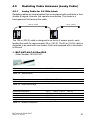
1
Antenna Guide Wireless LAN Antennas of the BAT family BAT Antenna Guide BAT Release 09 05/2015 Technical Support https://hirschmann-support.belden.eu.com The naming of copyrighted trademarks in this manual, even when not specially indicated, should not be taken to mean that these names may be considered as free in the sense of the trademark and tradename protection law and hence that they may be freely used by anyone. © 2015 Hirschmann Automation and Control GmbH Manuals and software are protected by copyright. All rights reserved. The copying, reproduction, translation, conversion into any electronic medium or machine scannable form is not permitted, either in whole or in part. An exception is the preparation of a backup copy of the software for your own use. For devices with embedded software, the end-user license agreement on the enclosed CD/DVD applies. The performance features described here are binding only if they have been expressly agreed when the contract was made. This document was produced by Hirschmann Automation and Control GmbH according to the best of the company's knowledge. Hirschmann reserves the right to change the contents of this document without prior notice. Hirschmann can give no guarantee in respect of the correctness or accuracy of the information in this document. Hirschmann can accept no responsibility for damages, resulting from the use of the network components or the associated operating software. In addition, we refer to the conditions of use specified in the license contract. You can get the latest version of this manual on the Internet at the Hirschmann product site (www.hirschmann.com). Hirschmann Automation and Control GmbH Stuttgarter Str. 45-51 72654 Neckartenzlingen Germany Tel.: +49 1805 141538 BAT Antenna Guide 11.05.2015 Contents Introduction 5 1 Current BAT portfolio 6 2 AP / Cable / Antenna assembly 8 3 Antenna Selection Criteria 9 4 External antennas 14 4.1 Legal regulations for operation external antennas 4.1.1 Relevant for use in the USA and in Canada:FCC compliant antennas 4.1.2 Relevant for use in Japan: 14 4.2 4.3 4.4 4.5 14 19 Omni-Directional Antennas 4.2.1 Omni-Directional Antenna for 2.4 GHz band 4.2.2 Omnidirectional antenna for 5 GHz band 4.2.3 Omnidirectional Antenna for 2.4 and 5 GHz band 4.2.4 Omni-directional dual-band antennae for MiMo for the 2.4 GHz and 5 GHz bands 4.2.5 Dual band Hemispherical Antenna for 2.4 and 5 GHz band 21 21 22 24 Sector Antennas 4.3.1 Directional antenna for the 2.4 GHz band with 8 dBi gain 4.3.2 Polarization-diversity antenna for 5 GHz band, linear 4.3.3 Sectoral MiMoantenna for 5 GHz band 34 30 31 34 36 38 Directional Antennas 4.4.1 Directional antenna for the 2.4 GHz band with 14 dBi gain 4.4.2 Directional antenna for 5 GHz band with 18 dBi gain 4.4.3 Directional antenna for 5 GHz band with a gain of 23 dBi 4.4.4 Directional antenna for 5 GHz band with 18 dBi gain 46 48 Radiating Cable Antennas (Leaky Cable) 4.5.1 Leaky Cable for 2.4 GHz; black 51 51 BAT Antenna Guide BAT Release 09 05/2015 40 40 43 3 5 Cables/Adapter 55 A Explanation of passive antennas in explosive hazard areas 61 B Antenna diagrams 62 C Index 66 D Further Support 67 4 BAT Antenna Guide BAT Release 09 05/2015 Introduction Since 2004, Hirschmann Automation and Control GmbH has provided a continually expanding product portfolio relating to WLAN. Our product portfolio comprises the following integral WLAN network elements: active devices such as access points, and clients passive components such as cables, antennas, and overvoltage protectors With our product portfolio, we focus on a high industrial suitability. In order to improve our products, in particular with regard to vibration resistance, grounding behavior, impermeability and emission behavior, we have further developed our antenna portfolio. You benefit from the following modifications of our antenna portfolio: All antennas comply with the IP65 degree of protection for a high industrial suitability. The sole exception to this is the BAT-ANT-N-14GIP23 antenna. The emission behavior of the new antennas is more homogeneous, with improved transmit and receive power during operation. The new antennas, equipped with N sockets, allow you to connect the antennas easily and quickly with other cables and overvoltage protectors. The scope of delivery comprises a complete solution, with the antenna, 1 yard of cable, and the pigtail included. The complete solution allows you to immediately connect the antenna to the BAT-C, BAT-F, BAT-R, and BAT300-Rail. You obtain every antenna with mounting material which is vibration resistant, weatherproof, and sturdy. We continually improve our product portfolio and include in the portfolio WLAN technology innovations. As a result, our portfolio is subject to short term changes. Check regularly for updates of our portfolio by visiting the Hirschmann product pages (www.hirschmann.com). BAT Antenna Guide BAT Release 09 05/2015 5 1 Current BAT portfolio In the following you get an overview of our devices. You also obtain information on which WLAN standards the devices support. The products of the BAT300 family support the WLAN standards IEEE 802.11a/b/g/h and 802.11n and can be operated with a gross data rate of up to 300 MBit/s. The products of the OpenBAT family support the IEEE 802.11a/b/g/h/n WLAN standards and can be operated with a gross data rate of up to 450 MBit/s. The BAT-C products support the WLAN standards IEEE 802.11a/b/g/h/n and can be operated with a gross data rate of up to 65 MBit/s. 6 BAT Antenna Guide BAT Release 09 05/2015 BAT Antenna Guide BAT Release 09 05/2015 BAT300-Rail The devices are supplied in metal enclosures for mounting on DIN rails in automation or vehicle applications. BAT300-F The devices are supplied in IP65/67 metal housings. They are designed for fieldlevel applications or harsh industrial environments. BAT-F X2 The devices are supplied with stainless steel covers. They are designed for hazardous environments and are approved for ATEX zone 2. BAT300-Rail BAT300-F BAT-F X2 Table 1: BAT-F The devices are supplied in a metal housing that can be fastened to DIN rails using automation technology. They provide impressive flexibility and high speeds. BAT-F BAT-R The devices are supplied in a metal housing that can be fastened to DIN rails using automation technology. They provide impressive flexibility and high speeds. BAT-R BAT-Family: Overview For further information, see the installation user manual for the corresponding device. BAT-C The devices are supplied with an IP67 aluminum housing. They are suitable for use in an industrial environment. BAT-C 7 2 AP / Cable / Antenna assembly Access Point Pigtail Optional Protector Optional Cable (2 m, 5 m, 15 m / 6.56. ft, 16.4 ft, 49.2 ft) 1×–3× 1×–3× Cable 1m Linear antenna 1×–3× BAT300-F / BAT-F / BAT-C Dual Slant antenna 1×–3× 1×–3× 1×–3× BAT300-Rail / BAT-R MiMo antenna f-m f-m f-m m-f As every antenna set includes 1 yard of antenna cable and a pigtail, you have the option of immediately connecting both AP types BAT-F / BAT300-F/ BATC, and BAT-R/ BAT300-Rail to the antennas. The BAT Protector can be screwed onto the BAT-F/ BAT300-F/ BAT-C directly, or be connected between two cables, as it is equipped with a plug and a socket. 8 BAT Antenna Guide BAT Release 09 05/2015 3 Antenna Selection Criteria Take into account the national regulations that apply to the operation of antennas before considering any other criteria. See “Legal regulations for operation external antennas” on page 14. Note: Hirschmann recommends that you perform an on-site inspection and an analysis to prepare for the installation of a WLAN. Typical antenna ranges, based on the frequency range and the antenna type: Frequency range: 2.4 GHz – Short range: up to 218 yards (200 m) with omnidirectional antennas. – Medium range: up to 0.62 miles (1 km) with sector antennas. – Long range: up to 3.11 miles (5 km) with directional antennas. Frequency range: 5 GHz – Short range: up to 328 yards (300 m) with omnidirectional antennas. – Medium range: up to 1.86 miles (3 km) with sector antennas. – Long range: up to 9.32 miles (15 km) with directional antennas. The typical ranges provide orientation for the first-time antenna selection. The actual antenna range depends on several factors such as output power, line of sight, and interference. In the following table you find antenna descriptions. Together with the above described typical ranges, the descriptions provide orientation for the first-time antenna selection. BAT Antenna Guide BAT Release 09 05/2015 9 10 Art.-No Antenna Description BAT-C 943 981-002 BAT-ANT-N-6G-IP65 Omnidirectional antenna for 2.4 GHz band +++ BAT300 family OpenBAT family BAT300BAT300-F BAT-R BAT-F Rail + + + + 943 981-003 BAT-ANT-N-5A-IP65 Omnidirectional antenna for 5 GHz band +++ + + + + 942 110-001 BAT-ANT-N-3AGN-IP67 Omnidirectional antenna for 2.4 GHz band and 5 GHz band +++ - + - + 942 047-001 BAT-ANT-N-3AGN-F Omnidirectional antenna for 2.4 GHz band and 5 GHz band +++ - + - + Release 09 05/2015 BAT Antenna Guide BAT Table 2: +++ very good; ++ good; + possible; – cannot be used; nr = not relevant Whether an antenna is actually suitable depends on the application case. BAT Antenna Guide BAT Release 09 05/2015 BAT300 family OpenBAT family BAT300BAT300-F BAT-R BAT-F Rail + + - Art.-No Antenna Description BAT-C 942 046-001 BAT-ANT-RSMA-2AGNR Omnidirectional antenna for 2.4 GHz band and 5 GHz band - 943 981-004 BAT-ANT-N-6ABG-IP65 +++ Hemispherical antenna for 2.4 GHz band and 5 GHz band + + + + 943 981-005 BAT-ANT-N-14G-IP23 Directional antenna for 2.4 GHz band with 14 dBi gain + + + + 943 981-006 BAT-ANT-N-18A-V-IP65 Directional antenna for 5 GHz band with 18 dBi gain ++ ++ ++ ++ 943 981-007 BAT-ANT-N-23A-V-IP65 Directional antenna for 5 GHz band with a high gain of 23 dBi + + + + 943 981-008 BAT-ANT-N-23A-VHIP65 Directional antenna for 5 GHz band with a high gain of 23 dBi +++ +++ +++ +++ Table 2: 11 +++ very good; ++ good; + possible; – cannot be used; nr = not relevant Whether an antenna is actually suitable depends on the application case. 12 Release 09 05/2015 BAT Antenna Guide BAT Art.-No Antenna Description 943 981-014 BAT-ANT-N-MiMo-18NIP65 Directional antenna for 5 GHz band with 18 dBi gain 943 981-009 BAT-ANT-N-8G-DS-IP65 Polarizationdiversity antenna for 2.4 GHz band, linear - ++ ++ ++ ++ 943 981-010 BAT-ANT-N-9A-DS-IP65 Polarizationdiversity antenna for 5 GHz band, linear - ++ ++ ++ ++ 943 981-012 BAT-ANT-N-MiMoDB5N-IP65 - +++ +++ +++ 943 981-013 BAT-ANT-N-MiMo5-9NIP65 Omni-directional dual-band antenna for MiMo for the 2.4 GHz and 5 GHz bands Sectoral MiMoantenna for 5 GHz band +++ +++ +++ +++ 943 981-001 BAT-ANT-N-LC-G-50mIP65 Leaky wave conductor for 2.4 GHz, black, 50m +++ +++ +++ +++ Table 2: BAT-C BAT300 family OpenBAT family BAT300BAT300-F BAT-R BAT-F Rail +++ +++ +++ +++ +++ +++ very good; ++ good; + possible; – cannot be used; nr = not relevant Whether an antenna is actually suitable depends on the application case. BAT Antenna Guide BAT Release 09 05/2015 Art.-No Antenna Description BAT-C 943 981-101 BAT-ANT-N-LC-G-100mIP65 +++ 943 903-373 BAT-ANT-Protector m-f Leaky wave conductor for 2.4 GHz, black, 100m Overvoltage Protector BAT300 family OpenBAT family BAT300BAT300-F BAT-R BAT-F Rail +++ +++ +++ +++ +++ +++ +++ +++ +++ 943 903-374 BAT-LAN-Protector IP68 Surge Arrestor LAN/PoE +++ +++ +++ +++ +++ 943 903-360 BAT-Pigtail nr Adapter cable (N socket/RP-SMA plug) +++ - +++ - 943 903-514 BAT-CLB-2 N m-f Antenna Cable N-Plug to N-Jack 2 m (6.56 ft) +++ +++ +++ +++ +++ 943 903-516 BAT-CLB-5 N m-f Antenna Cable N-Plug to N-Jack 5 m (16.40 ft) +++ +++ +++ +++ +++ 943 903-515 BAT-CLB-15 N m-f Antenna Cable N-Plug to N-Jack 15 m (49.21 ft) +++ +++ +++ +++ +++ Table 2: +++ very good; ++ good; + possible; – cannot be used; nr = not relevant Whether an antenna is actually suitable depends on the application case. 13 4 External antennas This chapter is structured as follows: “Legal regulations for operation external antennas” on page 14 “Omni-Directional Antennas” on page 21 “Sector Antennas” on page 34 “Directional Antennas” on page 40 “Radiating Cable Antennas (Leaky Cable)” on page 51 4.1 Legal regulations for operation external antennas You find additional information on approvals, certifications, and selfdeclarations in the Installation user manuals for the devices. Before operating the antennas, refer to the “Safety instructions” chapter in the Installation user manual for your device or devices. 4.1.1 Relevant for use in the USA and in Canada: FCC compliant antennas For the operation of the OpenBAT devices in the USA and in Canada— characteristic value US for country approvals—you require a permit for the operation of antennas. If the operation of a specific antenna is legal depends on the frequency band and the WLAN module used. The following tables provide you an overview of the approved antennas. 14 BAT Antenna Guide BAT Release 09 05/2015 BAT Antenna Guide BAT Release 09 05/2015 Art.-No Permitted band of operation 2.4 GHz band 5.15 GHz ... 5.25 GHz band Yes Yes 5.725 GHz ... 5.825 GHz band Yes Antennas operating with this device model: BAT-ANT-RSMA-2AGN-R Description 942 110001 BAT-ANT-N-3AGN-IP67 Omnidirectional antenna for 2.4 GHz band and 5 GHz band Yes Yes Yes 943 981012 BAT-ANT-N-MiMoDB-5N-IP65 Omni-directional Yes dual-band antenna for MiMo for the 2.4 GHz and 5 GHz bands Yes Yes Table 3: This table applies exclusively to OpenBAT devices that are labeled as follows: Contains Transmitter Module FCC ID: U99EWLAN1 IC: 4019A-EWLAN1 942 046001 Omnidirectional antenna for 2.4 GHz band and 5 GHz band 15 16 Art.-No 943 981013 Antennas operating with this device model: BAT-ANT-N-MiMo5-9N-IP65 Description Sectoral MiMoantenna for 5 GHz band Polarizationdiversity antenna for 2.4 GHz band, linear Permitted band of operation 2.4 GHz band 5.15 GHz ... 5.25 GHz band No Yes 5.725 GHz ... 5.825 GHz band Yes Yes No 943 981009 BAT-ANT-N-8G-DS-IP65 Table 3: This table applies exclusively to OpenBAT devices that are labeled as follows: Contains Transmitter Module FCC ID: U99EWLAN1 IC: 4019A-EWLAN1 No The use of antennas missing in this list is strictly prohibited. The required antenna impedance is 50 ohms. Release 09 05/2015 BAT Antenna Guide BAT BAT Antenna Guide BAT Release 09 05/2015 Art.-No 942 046-001 Antennas operating with this device model: BAT-ANT-RSMA-2AGN-R 942 110-001 BAT-ANT-N-3AGN-IP67 Omnidirectional antenna for 2.4 GHz band and 5 GHz band Yes Yes Yes 943 981-012 BAT-ANT-N-MiMoDB-5NIP65 Yes Yes 943 981-013 BAT-ANT-N-MiMo5-9N-IP65 Omni-directional Yes dual-band antenna for MiMo for the 2.4 GHz and 5 GHz bands Sectoral No MiMoantenna for 5 GHz band Yes Yes Table 4: Description Permitted band of operation 2.4 GHz band 5.15 GHz ... 5.725 GHz ... 5.825 5.25 GHz band GHz band Yes Yes Yes Omnidirectional antenna for 2.4 GHz band and 5 GHz band This table applies exclusively to OpenBAT devices that are labeled as follows: Contains Transmitter Module FCC ID: U99EWLAN2 IC: 4019A-EWLAN2 17 18 Art.-No 943 981-009 Antennas operating with this device model: BAT-ANT-N-8G-DS-IP65 943 981-014 BAT-ANT-N-MiMo-18N-IP65 Table 4: Description Polarizationdiversity antenna for 2.4 GHz band, linear Permitted band of operation 2.4 GHz band 5.15 GHz ... 5.725 GHz ... 5.825 5.25 GHz band GHz band Yes No No Directional antenna No for 5 GHz band with 18 dBi gain No Yes This table applies exclusively to OpenBAT devices that are labeled as follows: Contains Transmitter Module FCC ID: U99EWLAN2 IC: 4019A-EWLAN2 The use of antennas missing in this list is strictly prohibited. The required antenna impedance is 50 ohms. Release 09 05/2015 BAT Antenna Guide BAT 4.1.2 Relevant for use in Japan: The following table applies to OpenBAT variants with the characteristic value JP (Japan) that are labeled as follows: "Contains MIC ID: 204-310014" "5GHz band: この製品は屋内においてのみ使用可能です " Art.-No 942 110001 Antennas operating with this device model: BAT-ANT-N3AGN-IP67 Description Permitted band of operation 2.4 GHz 5 GHz band band Omnidirectional antenna for 2.4 GHz band and 5 GHz band Ja Ja 942 046001 BAT-ANTRSMA-2AGNR Omnidirectional antenna for 2.4 GHz band and 5 GHz band Ja Ja 943 981004 BAT-ANT-N6ABG-IP65 Hemispherical Ja antenna for 2.4 GHz band and 5 GHz band Ja 943 981012 BAT-ANT-NMiMoDB-5NIP65 Ja 943 981009 BAT-ANT-N8G-DS-IP65 Omni-directional Ja dual-band antenna for MiMo for the 2.4 GHz and 5 GHz bands PolarizationJa diversity antenna for 2.4 GHz band, linear 943 981010 BAT-ANT-N9A-DS-IP65 Polarizationdiversity antenna for 5 GHz band, linear Nein Ja 943 981002 BAT-ANT-N6G-IP65 Omnidirectional antenna for 2.4 GHz band Ja Nein BAT Antenna Guide BAT Release 09 05/2015 Nein 19 Art.-No 943 981003 943 981013 Permitted band of operation 2.4 GHz 5 GHz band band Antennas operating with this device model: BAT-ANT-N5A-IP65 Description Omnidirectional antenna for 5 GHz band Nein Ja BAT-ANT-NMiMo5-9NIP65 Sectoral MiMoantenna for 5 GHz band Nein Ja Using antennas that are not on this list is prohibited. The 5 GHz band is restricted to indoor usage. 20 BAT Antenna Guide BAT Release 09 05/2015 4.2 Omni-Directional Antennas 4.2.1 Omni-Directional Antenna for 2.4 GHz band BAT-ANT-N-6G-IP65 Order Number: 943 981-002 Radiation Pattern Horizontal 2,400 MHz Vertical 2,400 MHz -90 0 -120 -60 -150 -30 180 -40 -30 -20 -10 150 0 30 120 60 90 Frequency range Gain VSWR (voltage standing wave ratio) Polarization HPBW (half power bandwidth) Downtilt Max. Power Impedance Connector Table 5: 30 -30 60 0 -60 90 -40 -30 -20 -10 120 0 -90 -120 150 -150 180 2400 MHz ... 2500 MHz 6.0 dBi < 1.8 Linear, vertical horizontal 360° 0° 25 W 50 Ω N female Electrical Specification BAT Antenna Guide BAT Release 09 05/2015 21 Temperature Radome color Radome material Weight Dimensions Protection class Table 6: −40 °F ... 176 °F (−40 °C ... +80 °C) Grey-white Fiber glass 0.75 lb (0.34 kg) ø 0.87 in × 9.84 in (ø 22 mm × 250 mm) IP65 Environmental & Mechanical Characteristics 3.28 ft (1 m ) with N male connectors at both ends. Pigtail, R-SMA male to N female Mounting material Table 7: Cable and Accessories 4.2.2 Omnidirectional antenna for 5 GHz band BAT-ANT-N-5A-IP65 Order Number: 943 981-003 Radiation Pattern horizontal 5470 MHz vertical 5470 MHz 0 -90 -120 -150 -40 -30 -20 -10 150 0 30 120 60 90 30 -60 -30 180 22 -30 -60 0 60 -90 -40 -30 -20 -10 -120 0 90 120 -150 150 180 BAT Antenna Guide BAT Release 09 05/2015 Frequency range Gain VSWR (voltage standing wave ratio) Polarization HPBW (half power bandwidth) HPBW (half power bandwidth) Max. Power Impedance Connector Table 8: Electrical Specification Temperature Radome color Radome material Weight Dimensions Protection class Table 9: 5150 MHz ... 5875 MHz 5 dBi 1.5 Linear, vertical horizontal 360° vertical 25° 6W 50 Ω N female −49 °F ... +158 °F (−45 °C ... +70 °C) Grey-white Polypropylene 0.66 lb (0.3 kg) 0.63 in. × 6.30 in. (16 mm × 160 mm) IP65 Environmental & Mechanical Characteristics 3.28 ft (1 m ) with N male connectors at both ends. Pigtail, R-SMA male to N female Mounting material Table 10: Cable and Accessories BAT Antenna Guide BAT Release 09 05/2015 23 4.2.3 Omnidirectional Antenna for 2.4 and 5 GHz band BAT-ANT-N-3AGN-IP67 Order number: 942 110-001 (10 pcs.) mm inch Ø 12.9 Ø 0.50 80 ±2 3.15 ±0.08 Ø 12.9 Ø 0.50 Ø 20 Ø 0.79 Radiation Pattern horizontal 2.4 GHz horizontal 5 GHz 90 10 120 90 H_Plane 2400 2450 2500 60 0 30 150 -10 180 0 330 210 30 150 -30 180 0 -10 330 210 0 240 300 270 24 0 -20 0 10 H_Plane 5150 5250 5350 5450 5550 5650 5750 5850 60 -20 -20 -10 120 -10 -20 -30 10 10 240 300 270 BAT Antenna Guide BAT Release 09 05/2015 vertical 2.4 GHz vertical 5 GHz 90 10 120 90 0 180 -30 0 180 0 -20 -10 330 210 0 10 30 -20 -20 -10 E_Plane 5150 5250 5350 5450 5550 5650 5750 5850 60 150 -10 -20 -30 120 0 30 150 -10 10 E_Plane 2400 2450 2500 60 330 210 0 240 300 10 240 270 Frequency range Gain VSWR (voltage standing wave ratio) Polarization HPBW (half power bandwidth) HPBW (half power bandwidth) Max. Power Impedance Connector 300 270 2400 MHz ... 2485 MHz 2.0 dBi ≤2.0 Linear, vertical horizontal 360° vertical 30° 2W 50 Ω N-type male 5150 MHz ... 5850 MHz 2.0 dBi vertical 15° Table 11: Electrical Specification Temperature Radome color Radome material Weight Dimensions Protection class −40 °F ... +185 °F (−40 °C ... +85 °C) Black PC 1.23 oz (35 g) 0.79 in. × 3.15 in. (20 mm × 80 mm) IP65 / IP67 Table 12: Environmental & Mechanical Characteristics BAT Antenna Guide BAT Release 09 05/2015 25 BAT-ANT-N-3AGN-F Order Number: 942 047-001 (10 pcs.) The antenna is supplied with all BAT-F and BAT-C devices. 183 7.2 mm inch 22 0.87 The antenna is directly screwed on the BAT. Radiation Pattern Horizontal 2,400 MHz 26 Horizontal 5,000 MHz BAT Antenna Guide BAT Release 09 05/2015 Vertical 2,400 MHz Vertical 5,000 MHz Frequency range Gain VSWR (voltage standing wave ratio) Polarization 2400 MHz - 2500 MHz 2.5 dBi 2.0 Linear, vertical HPBW (half power bandwidth) horizontal 360° HPBW (half power bandwidth) Max. Power vertical 30° 2W Impedance 50 Ω Connector N-type male 5150 MHz ... 5875 MHz 5.0 dBi vertical 15° Table 13: Electrical Specification Temperature Radome color Radome material Weight Dimensions Protection class −40 °F ... +158 °F (−40 °C ... +70 °C) Grey-white ABS 2.47 oz (70 g) 22 mm x 183 mm (0.87 in x 7.20 in) IP65 Table 14: Environmental & Mechanical Characteristics Note: The antenna BAT-ANT-N-3AGN-F is specified solely for usage with the WLAN Client BAT-C in the regions EU, USA and Canada. BAT Antenna Guide BAT Release 09 05/2015 27 BAT-ANT-RSMA-2AGN-R Order Number: 942 046-001 (10 pcs.) 159.8 ± 2 90 ° Radiation Pattern horizontal 2450 MHz vertical 2450 MHz horizontal 5250 MHz vertical 5250 MHz 28 30.2 1.19 Ø 12.5 Ø 0.49 6.29 ± 0.08 mm inch 21.2 0.83 BAT Antenna Guide BAT Release 09 05/2015 horizontal 5750 MHz Frequency range Gain VSWR (voltage standing wave ratio) Polarization HPBW (half power bandwidth) HPBW (half power bandwidth) Impedance Connector vertical 5750 MHz 2400 MHz 3 dBi 2.0 Linear, vertical horizontal 360° vertical 30° 50 Ω Reverse-SMA male 5250 MHz and 5750 MHz 5 dBi vertical 15° Table 15: Electrical Specification Temperature Radome color Radome material Weight Dimensions −4 °F ... +149 °F (−20 °C ... +65 °C) Black PC/PU 0.92 oz (26 g) 0.83 in × 6.3 in (21 mm × 160 mm) Table 16: Environmental & Mechanical Characteristics BAT Antenna Guide BAT Release 09 05/2015 29 4.2.4 Omni-directional dual-band antennae for MiMo for the 2.4 GHz and 5 GHz bands BAT-ANT-N-MiMoDB-5N-IP65 Order Number: 943 981-012 Radiation Pattern Horizontal 2,400 MHz Vertical 2,400 MHz port 1 port 2 port 3 180 150 -150 120 150 -30 -20 -10 60 -40 0 -60 30 -120 90 -90 -40 -150 120 -120 90 port 1 port 2 port 3 180 -30 -20 -10 60 -30 -90 0 -60 30 -30 0 horizontal 5470 MHz vertical 5470 MHz port 1 port 2 port 3 180 150 -150 120 -40 -30 -20 -10 60 0 -60 30 -30 0 30 150 -120 90 -90 port 1 port 2 port 3 180 -150 120 -120 90 -40 -30 -20 -10 60 0 -90 -60 30 -30 0 BAT Antenna Guide BAT Release 09 05/2015 Frequency range Gain VSWR (voltage standing wave ratio) Polarization HPBW (half power bandwidth) Downtilt Max. Power Impedance Connector 2400 MHz ... 2500 MHz 5150 MHz ... 5875 MHz 3.5 dBi / 5.5 dBi 1.8 3 × Linear, vertical horizontal 360° 0° 2W 50 Ω 3 × N male at 3.28 ft (1 m) cable directly attached Table 17: Electrical Specification Temperature Radome color Radome material Weight Dimensions Protection class −40 °F ... 176 °F (−40 °C ... +80 °C) 7035 (Light Gray) plastic 0.66 lb (0.3 kg) 12.2 in × 4.33 in × 1.57 in (310 mm × 110 mm × 40 mm) IP65 Table 18: Environmental & Mechanical Characteristics 3 × 3 ft (90 cm) directly mounted to the antenna with N male connectors 3 × Pigtail, R-SMA male to N female Mounting material Table 19: Cable and Accessories 4.2.5 Dual band Hemispherical Antenna for 2.4 and 5 GHz band BAT-ANT-N-6ABG-IP65 Order Number: 943 981-004 Radiation Pattern Horizontal 2,400 MHz BAT Antenna Guide BAT Release 09 05/2015 Vertical 2,400 MHz 31 0 0 -30 30 -60 30 60 -90 -40 -30 -20 -10 -120 0 60 90 -60 90 120 -150 -30 -40 150 0 -90 -150 180 vertical 5470 MHz 0 0 -30 30 -60 30 60 -30 -20 -10 -120 0 120 -150 -10 -120 150 horizontal 5470 MHz -40 -20 120 180 -90 -30 -30 60 90 -60 90 -40 -30 -20 -10 0 120 150 -120 150 180 -90 -150 180 17.7 0.7 mm inch Ø 4.5 8 Ø 0.1 70 2.7 6 Ø 43.92 Ø 1.73 Ø 86 Ø 3.39 42.89 1.69 32 BAT Antenna Guide BAT Release 09 05/2015 Frequency range Impedance VSWR (voltage standing wave ratio) Polarization Gain 3 dB beamwidth horizontal 3 dB beamwidth horizontal Max. Power 2300 MHz ... 2500 MHz 4900 MHz ... 5935 MHz 50 Ω 1.8 Linear, vertical 6 dBi at 2.4 GHz 8 dBi at 5 GHz at 2.4 GHz 360° at 5 GHz 173° 75 W (CW) at 77 °F (25 °C) Table 20: Electrical Specification 3.28 ft (1 m ) with N male connectors at both ends. Pigtail, R-SMA male to N female Table 21: Cable and Accessories BAT Antenna Guide BAT Release 09 05/2015 33 4.3 Sector Antennas 4.3.1 Directional antenna for the 2.4 GHz band with 8 dBi gain BAT-ANT-N-8G-DS-IP65 Order Number: 943 981-009 Radiation Pattern Horizontal 2,400 MHz Vertical 2,400 MHz -90 90 -120 -60 -150 120 -30 180 -20 -10 -6 -3 150 0 150 0 30 120 60 60 90 30 180 -20 -10 -6 -3 -150 0 0 -30 -120 -60 -90 Table 22: Directional characteristic Frequency range Impedance VSWR (voltage standing wave ratio) Polarization Gain 3 dB beamwidth horizontal 3 dB beamwidth vertical Downtilt Isolation between ports Front to back ratio 2400 MHz ... 2485 MHz 50 Ω 1.5 dual linear, ± 45° slant 8 dBi 75° 70° 0° 25 dB 14 dB Table 23: Electrical Specification 34 BAT Antenna Guide BAT Release 09 05/2015 Max. Power Connector 10 W (CW) at 77 °F (25 °C) 2 × N female Table 23: Electrical Specification Dimensions Weight Radome material Radome color Operating temperature range Storage temperature range Windload Protection class 3.98 in × 3.15 in × 1.38 in (101 mm × 80 mm × 35 mm) 0.24 lb (0.11 kg) LEXAN EXL 9330 RAL 7044 (silk gray) −40 °F ... 176 °F (−40 °C ... +80 °C) −40 °F ... 176 °F (−40 °C ... +80 °C) 3.37 lbf at 99 m/h (15 N at 160 km/h) IP65 Table 24: Mechanical Properties 2 × 3.28 ft (1 m) with N male connectors at both ends 2 × Pigtail, R-SMA male to N female Mounting material Table 25: Cable and Accessories BAT Antenna Guide BAT Release 09 05/2015 35 4.3.2 Polarization-diversity antenna for 5 GHz band, linear BAT-ANT-N-9A-DS-IP65 Order Number: 943 981-010 Radiation Pattern horizontal 5470 MHz vertical 5470 MHz 90 -90 -120 120 -60 -150 150 -30 180 -20 -10 -6 -3 150 0 0 30 120 60 30 180 -20 -6 -3 -150 0 0 -30 -120 60 -10 -60 -90 90 81 3.19 26.1 1.03 100 3.94 35 1.38 mm inch Frequency range Impedance 5150 MHz ... 5925 MHz 50 Ω Table 26: Electrical Specification 36 BAT Antenna Guide BAT Release 09 05/2015 VSWR (voltage standing wave ratio) Polarization Gain 3 dB beamwidth horizontal 3 dB beamwidth vertical Downtilt Isolation between ports Front to back ratio Max. Power Connector 2 dual linear, ± 45° slant 9 dBi 70° 60° 0° 20 dB 20 dB 10 W (CW) at 77 °F (25 °C) 2 × N female Table 26: Electrical Specification Dimensions Weight Housing material Radome material Radome material Radome color Operating temperature range Storage temperature range Windload Protection class 3.98 in × 3.15 in × 1.38 in (101 mm × 80 mm × 35 mm) 0.24 lb (0.11 kg) ASA and aluminum ASA LEXAN EXL 9330 RAL 7044 (silk gray) −40 °F ... 176 °F (−40 °C ... +80 °C) −40 °F ... 176 °F (−40 °C ... +80 °C) 3.37 lbf at 99 m/h (15 N at 160 km/h) IP65 Table 27: Mechanical Properties 2 × 3.28 ft (1 m) with N male connectors at both ends 2 × Pigtail, R-SMA male to N female Mounting material Table 28: Cable and Accessories BAT Antenna Guide BAT Release 09 05/2015 37 4.3.3 Sectoral MiMoantenna for 5 GHz band BAT-ANT-N-MiMo5-9N-IP65 Order Number: 943 981-013 Radiation Pattern horizontal – connection 1 vertical – connection 1 -90 90 -120 -60 -150 120 -30 180 -40 -30 -20 -10 150 0 150 0 30 120 30 180 -40 60 0 -60 vertical – connection 2 90 -60 -150 120 -30 -30 -20 -10 150 38 0 -30 -90 0 30 60 90 -10 -90 -120 120 -20 -120 horizontal – connection 2 -40 -30 -150 90 180 60 60 150 0 30 180 -40 -30 -20 -10 -150 0 0 -30 -120 -60 -90 BAT Antenna Guide BAT Release 09 05/2015 horizontal – connection 3 vertical – connection 3 -90 90 -120 -60 -150 120 -30 180 -40 -30 -20 -10 150 0 150 0 30 120 60 180 -40 -30 -20 -10 -150 60 0 0 -30 -120 90 Frequency range Impedance VSWR (voltage standing wave ratio) Polarization Gain 3 dB beamwidth horizontal 3 dB beamwidth vertical Downtilt Max. Power Connector 30 -60 -90 5150 MHz ... 5875 MHz 50 Ω 1.5 3 × linear vertical / horizontal / +45° 9 dBi 65° 65° 0° 2 W (CW) at 77 °F (25 °C) N female Table 29: Electrical Specification Dimensions Weight Radome material Radome color Operating temperature range Storage temperature range Windload Protection class 3.98 in × 3.15 in × 1.38 in (101 mm × 80 mm × 35 mm) 0.24 lb (0.11 kg) LEXAN EXL 9330 RAL 7044 (silk gray) −40 °F ... 176 °F (−40 °C ... +80 °C) −40 °F ... 176 °F (−40 °C ... +80 °C) 3.37 lbf at 99 m/h (15 N at 160 km/h) IP65 Table 30: Mechanical Properties 3 × 3.28 ft (1 m) with N male connectors at both ends 3 × Pigtail, R-SMA male to N female Mounting material Table 31: Cable and Accessories BAT Antenna Guide BAT Release 09 05/2015 39 4.4 Directional Antennas 4.4.1 Directional antenna for the 2.4 GHz band with 14 dBi gain BAT-ANT-N-14G-IP23 Order Number: 943 981-005 Radiation Pattern Horizontal 2,400 MHz Vertical 2,400 MHz -90 90 -120 -60 -150 -30 180 -20 -10 -6 -3 150 0 30 120 60 90 40 120 60 150 0 30 180 -20 -10 -6 -3 -150 0 0 -30 -120 -60 -90 BAT Antenna Guide BAT Release 09 05/2015 4,3 0,17 200 7,87 222,01 8,74 mm inch 200 7,87 40 1,57 52,45 2,06 252,99 9,96 Frequency range Impedance VSWR (voltage standing wave ratio) Polarization Gain 3 dB beamwidth horizontal 3 dB beamwidth vertical Downtilt Front to back ratio Max. Power Connector 2300 MHz ... 2500 MHz 50 Ω 1.5 vertical 14 dBi 35° 30° 0° 20 dB 75 W (CW) at 77 °F (25 °C) N female Table 32: Electrical Specification Dimensions Weight Radome material Radome color Operating temperature range Storage temperature range Windload Protection class 3.98 in × 3.15 in × 1.38 in (101 mm × 80 mm × 35 mm) 0.24 lb (0.11 kg) LEXAN EXL 9330 RAL 7044 (silk gray) −40 °F ... 176 °F (−40 °C ... +80 °C) −40 °F ... 176 °F (−40 °C ... +80 °C) 3.37 lbf at 99 m/h (15 N at 160 km/h) IP23 Table 33: Mechanical Properties BAT Antenna Guide BAT Release 09 05/2015 41 3.28 ft (1 m ) with N male connectors at both ends. Pigtail, R-SMA male to N female Mounting material Table 34: Cable and Accessories Note: Applies for use in the EU: If you use the antenna BAT-ANT-N-14GIP23 in combination with OpenBAT family devices, use the supplied 1 m (3.28ft) antenna cable in combination with BAT-CLB-2 N m-f cable. 42 BAT Antenna Guide BAT Release 09 05/2015 4.4.2 Directional antenna for 5 GHz band with 18 dBi gain BAT-ANT-N-18A-V-IP65 Order Number: 943 981-006 Due to their compact design, several of these antennas can be mounted on a single post. For better separation of the spatial streams with MiMo, you mount the antennas with different alignments (polarizations). Example: 1st antenna: vertical 2nd antenna: horizontal 3rd antenna: 45° horizontal Radiation Pattern horizontal 5470 MHz vertical 5470 MHz -90 90 -120 -60 -150 120 -30 180 -20 -10 -6 -3 150 0 150 0 30 120 60 60 90 Frequency range Gain 30 180 -20 -10 -6 -3 -150 0 0 -30 -120 -60 -90 5150 MHz ... 5250 MHz 5250 MHz ... 5350 MHz 5350 MHz ... 5725 MHz 5725 MHz ... 5875 MHz 18 dBi 19 dBi 18.5 dBi 18 dBi Table 35: Electrical Specification BAT Antenna Guide BAT Release 09 05/2015 43 Polarization HPBW / horizontal HPBW / vertical Front to back ratio Power handling Impedance Connector Linear, vertical 18° 18° > 30 dB 6 W (CW) 50 Ω N Jack Table 35: Electrical Specification Windload @ wind speed Temperature Radome material Radome color Weight Dimensions Protection class 23.4 lbf at 64 m/h (104 N at 216 km/h) −49 °F ... +158 °F (−45 °C ... +70 °C) plastic 7035 (Light Gray) 0.11 kg, 0.24 lb 7.48 in × 7.48 in × 1.2 in (190 mm × 190 mm × 30.5 mm) IP65 / IP67 Table 36: Environmental & Mechanical Characteristics 3.28 ft (1 m ) with N male connectors at both ends. Pigtail, R-SMA male to N female Mounting material Table 37: Cable and Accessories BAT-ANT-N-23A-V-IP65 Order Number: 943 981-007 Relevant for North America: Operate the antennas BAT-ANT-N-23A-V-IP65 and BAT-ANT-N-23AVH-IP65 exclusively in point-to-point connections. Due to their compact design, several of these antennas can be mounted on a single post. For better separation of the spatial streams with MiMo, you mount the antennas with different alignments (polarizations). Example: 44 BAT Antenna Guide BAT Release 09 05/2015 1st antenna: vertical 2nd antenna: horizontal 3rd antenna: 45° horizontal Radiation Pattern horizontal 5470 MHz vertical 5470 MHz 90 -90 -120 120 -60 -150 150 -30 180 -20 -10 -6 -3 150 0 0 30 120 60 60 30 180 -20 Gain VSWR (voltage standing wave ratio) Polarization HPBW / horizontal HPBW / vertical Front to back ratio Max. Power Impedance Connector -6 -3 -150 0 0 -30 -120 -60 -90 90 Frequency range -10 5150 MHz ... 5350 MHz 5470 MHz ... 5875 MHz 23 dBi < 1.5 Linear, vertical 9° 9° > 30 dB 6W 50 Ω N Jack Table 38: Electrical Specification Windload @ wind speed Temperature Radome material Radome color Weight Dimensions Protection class 59.3 lbf at 136 m/h (264N at 220 km/h) −49 °F ... +158 °F (−45 °C ... +70 °C) plastic Grey-white 3.31 lb (1.5 kg) 12.01 in × 12.01 in × 0.98 in (305 mm × 305 mm × 25 mm) IP65 / IP67 Table 39: Environmental & Mechanical Characteristics BAT Antenna Guide BAT Release 09 05/2015 45 3.28 ft (1 m ) with N male connectors at both ends. Pigtail, R-SMA male to N female Mounting material for wall and mast mount Table 40: Cable and Accessories 4.4.3 Directional antenna for 5 GHz band with a gain of 23 dBi BAT-ANT-N-23A-VH-IP65 Order Number: 943 981-008 Radiation Pattern Connection: horizontal / polarization: horizontal Connection: horizontal / polarization: vertical (5,470 MHz) (5,470 MHz) -90 90 -120 -60 -150 -30 180 -20 -10 -6 -3 150 0 30 120 60 90 46 120 60 150 0 30 180 -20 -10 -6 -3 -150 0 0 -30 -120 -60 -90 BAT Antenna Guide BAT Release 09 05/2015 Connection: vertical / polarization: horizontal (5,470 MHz) Connection: vertical / polarization: vertical (5,470 MHz) -90 90 -120 -60 -150 120 -30 180 -20 -10 -6 -3 150 0 150 0 30 120 60 30 180 -20 -6 -3 -150 60 0 0 -30 -120 90 Frequency range Gain VSWR (voltage standing wave ratio) Polarization HPBW / horizontal HPBW / vertical Front to back ratio Max. Power Impedance Connector -10 -60 -90 5150 MHz ... 5875 MHz 23 dBi < 1.7 dual Linear, vertical and horizontal 9° 9° −30 dB 6W 50 Ω 2 × N female Table 41: Electrical Specification Windload @ survival speed Temperature Radome material Radome color Weight Dimensions Protection class 59.3 lbf at 136 m/h (264N at 220 km/h) −49 °F ... +158 °F (−45 °C ... +70 °C) plastic Grey-white 5.51 lb (2.5 kg) 14.61 in. × 14.61 in. × 1.57 in. (371 mm × 371 mm × 40 mm) IP65 / IP67 Table 42: Environmental & Mechanical Characteristics 2 × 3.28 ft (1 m) with N male connectors at both ends 2 × Pigtail, R-SMA male to N female Mounting material for wall and mast mount Table 43: Cable and Accessories BAT Antenna Guide BAT Release 09 05/2015 47 4.4.4 Directional antenna for 5 GHz band with 18 dBi gain BAT-ANT-N-MiMo-18N-IP65 Order Number: 943 981-014 MiMo is achieved via polarization diversity. Relevant for North America: See “Legal regulations for operation external antennas” on page 14. mm 14 0.55 66 2.60 inch 60.9 2.36 305 12.0 60.9 2.36 +45° 72.8 2.83 63.3 2.48 Radiation Pattern 5 GHz horizontal - connection on the right (+45°) 48 15.5 0.59 –45° vertical - connection on the right (+45°) BAT Antenna Guide BAT Release 09 05/2015 Radiation Pattern Radiation Pattern Amplitude [dB] Azimuth [deg] Amplitude [dB] -90 -120 90 120 -60 -150 150 -30 180 -20 -10 -6 -3 0 0 150 30 180 30 120 -20 -120 -3 0 0 -60 -90 Elevation [deg] Horizontal-Plane: Copolar Vertical-Plane: Copolar horizontal - connection on the left (–45°) vertical - connection on the left (–45°) Radiation Pattern Radiation Pattern Amplitude [dB] -90 -120 -60 -30 -20 -10 -6 -3 0 150 60 150 0 30 180 30 120 90 120 -150 -20 -10 -6 -3 -150 60 0 -60 -90 Elevation [deg] Horizontal-Plane: Copolar 0 -30 -120 90 Vertical-Plane: Copolar horizontal - vertical connection vertical - vertical connection Horizontal-Plane: Copolar Radiation Pattern Amplitude [dB] Azimuth [deg] -6 -30 60 180 -10 -150 90 Amplitude [dB] Azimuth [deg] 60 Radiation Pattern -90 -120 Amplitude [dB] -60 90 120 -150 60 -30 150 180 -20 -10 -6 -3 150 0 30 120 Horizontal-Plane: Copolar BAT Antenna Guide BAT Release 09 05/2015 0 180 -20 -10 -6 -3 -150 60 90 30 0 0 -30 -120 Elevation [deg] -60 -90 Vertical-Plane: Copolar 49 Band 1 Band 2 Frequency range 4900 MHz ... 5150 MHz 5150 MHz ... 6000 MHz VSWR (voltage 1.8 1.8 standing wave ratio) Gain 17 dBi 18 dBi HPBW / vertical 20° Band 3 6000 MHz ... 6100 MHz 1.8 16 dBi 15° Table 44: Electrical Specification Polarization Max. Power Impedance Connector 0°, +/−45° inclination 6W 50 Ω N Jack Table 45: General data Windload @ survival speed Temperature Radome material Radome color Weight Dimensions Protection class 263 N at 136 m/h (263 N at 220 km/h) −49 °F ... +158 °F (−45 °C ... +70 °C) plastic Grey-white 3.31 lb (1.5 kg) 12.01 in × 12.01 in × 0.59 in (305 mm × 305 mm × 15 mm) IP67 Table 46: Environmental & Mechanical Characteristics 3 × 3.28 ft (1 m) with N male connectors at both ends 3 × Pigtail, R-SMA male to N female Mounting material for wall and mast mount Table 47: Cable and Accessories 50 BAT Antenna Guide BAT Release 09 05/2015 4.5 Radiating Cable Antennas (Leaky Cable) 4.5.1 Leaky Cable for 2.4 GHz; black Radiating cables are coaxial cables that are equipped with small slots in their shields at regular intervals that operate as antennas. This leads to a homogeneous field around the cable. 100 m; 328 ft 50 m; 164 ft The 100 m (328 ft) cable is designed to be fed by 2 access points, each feeding the cable for approximately 50 m (164 ft). The 50 m (164 ft) cable is designed to be used with one Access Point and equipped with a terminator at the end. BAT-ANT-N-LC-G-50m-IP65 Order Number: 943 981-001 Cable length Cable specification 164 ft (50 m) 2 × N male connectors; 0.15 dB at 2.4 GHz Table 48: Specification Frequency band Antenna connector 2000 MHz - 2900 MHz N-type male Table 49: Radio technology Operating temperature Storage/transport temperature Dimensions Protection class Weight −40 ºF ... +185 ºF (−40 ºC ... +85 ºC) −70 ºC ... +85 ºC 164 ft (50 m); d = 0.6 in (15 mm) IP65 26.5 lb (12 kg) Table 50: Ambient conditions BAT Antenna Guide BAT Release 09 05/2015 51 Halogen free and flame retardant outer sheath Low corrosive gas emission according to IEC 60754-2 Flame retardant according to IEC 60332-1 and IEC 60332-3 cat. C Low smoke emission according to IEC 61034 Table 51: Flammability Characteristics Leaky Cable 2 × N-connector, preassembled 1 × terminating resistor 50 Ohm 50 × fastening clip Table 52: Scope of delivery and accessories 52 BAT Antenna Guide BAT Release 09 05/2015 BAT-ANT-N-LC-G-100m-IP65 Order Number: 943 981-101 Cable length Cable specification 100 m, 328 ft 2 × N male connectors; 0.15 dB at 2.4 GHz Table 53: Specification Frequency band Antenna connector 2000 MHz - 2900 MHz N-type male Table 54: Radio technology Operating temperature Storage/transport temperature Dimensions Protection class Weight −40 ºF ... +185 ºF (−40 ºC ... +85 ºC) −70 ºC ... +85 ºC 328 ft (100 m); d = 0.6 in (15 mm) IP65 53 lb (24 kg) Table 55: Ambient conditions Halogen free and flame retardant outer sheath Low corrosive gas emission according to IEC 60754-2 Flame retardant according to IEC 60332-1 and IEC 60332-3 cat. C Low smoke emission according to IEC 61034 Table 56: Flammability Characteristics Leaky Cable 2 × N-connector, preassembled 1 × terminating resistor 50 Ohm 100 × fastening clip Table 57: Scope of delivery and accessories Configurations Longitudinal Attenuation db/328 ft (dB/100 m) LC at 4 in (10 cm) from a concrete floor 15 LC at 0.6 in (15 mm) from a metal surface 17 LC directly against a metal surface 34 Table 58: Longitudinal attenuation of both cables between 2.4 and 2.485 GHz BAT Antenna Guide BAT Release 09 05/2015 53 Figure 1: Mounting a leaky wave conductor in the tunnel. Fastening clips are included in the delivery. 54 BAT Antenna Guide BAT Release 09 05/2015 5 Cables/Adapter All antennas are supplied with 1 m cable / N-plug to N-jack and pigtail. BAT-CLB-2 N m-f, BAT-CLB-2 N f-f Order Number: m-m: 943 903-513 m-f: 943 903-514 Length Diameter Attenuation Connector Protection class 6.56 ft (2 m) 6 mm 1.4 dB / 2.4 GHz 3 dB / 5 GHz N male to female IP65 Table 59: Characteristics Temperature range Installation temperature range Flammability Halogen-free 2002/95/EC (RoHS) compliant −40 ºF ... +185 ºF (−40 ºC ... +85 ºC) −20 °C ... +60 °C UL 1581 § 1080 (VW-1) in compliance with IEC 60754 Table 60: Flammability Characteristics BAT Antenna Guide BAT Release 09 05/2015 55 BAT-CLB-5 N m-f Order Number: 943 903-516 Length Diameter Attenuation Connector 16.4 ft (5 m) 13 mm 1.3 dB / 2.4 GHz 2.3 dB / 5 GHz N male/ N female Table 61: Characteristics Temperature range Installation temperature range Flammability Halogen-free 2002/95/EC (RoHS) compliant −40 ºF ... +185 ºF (−40 ºC ... +85 ºC) −20 °C ... +60 °C UL 1581 § 1080 (VW-1) in compliance with IEC 60754 Table 62: Flammability Characteristics 56 BAT Antenna Guide BAT Release 09 05/2015 BAT-CLB-15 N m-f Order Number: 943 903-515 Length Diameter Attenuation Connector 49,2 ft (15 m) 13 mm 3 dB / 2.4 GHz 4 dB / 5 GHz N male/ N female Table 63: Characteristics Temperature range Installation temperature range Flammability Halogen-free 2002/95/EC (RoHS) compliant −40 ºF ... +185 ºF (−40 ºC ... +85 ºC) −20 °C ... +60 °C UL 1581 § 1080 (VW-1) in compliance with IEC 60754 Table 64: Flammability Characteristics BAT Antenna Guide BAT Release 09 05/2015 57 BAT-Pigtail Order Number: 943 903-360 Length Diameter Attenuation Connector 0.66 ft (0.2 m) 6 mm 0.5 dB / 2.4 GHz 1 dB / 5 GHz N female/ RPSMA-Plug Table 65: Characteristics 58 BAT Antenna Guide BAT Release 09 05/2015 BAT-ANT-Protector m-f Order Number: 943 903-373 The BAT-ANT-Protector m-f is a bandpass with electrical insulation. It helps prevent damage due to electrostatic discharging. The BAT-ANT-Protector m-f can enable a watertight connection to the switch cabinet. This device is strongly recommended to be used in- and outdoor wherever electrical discharge, overvoltage or unclear grounding occur. Please refer to the Outdoor Installation Guide for how to mount and plan the installation. Main path connectors Mounting and grounding Side of bulkhead Design specialty Connection 1: N socket, protected (electrically isolated) Connection 2: N socket, unprotected MH170/brk (MH=bulkhead mounting/brk=bracket) protected side inline design Table 66: Product Configuration Impedance Frequency range Return loss Insertion loss RF CW power Surge current handling capability Residual pulse energy 50 Ω 2000 MHz ... 6000 MHz ≥ 20 dB ≤ 0.2 dB ≤ 300 W 50 multiple kA (test pulse 8/20 μs) 0.0001 μJ typically (test pulse 4 kV 1.2/50 μs / 2 kA 8/20 μs) Main path - protected side Table 67: Electrical Specification Weight Operating temperature Waterproof degree 2002/95/EC (RoHS) 0.19 lb (0.085 kg) −40 ºF ... +185 ºF (−40 ºC ... +85 ºC) IP65 (according to IEC 60529, data refers to the coupled state) compliant Table 68: Environmental & Mechanical Characteristics BAT Antenna Guide BAT Release 09 05/2015 59 BAT-LAN-Protector IP68 Order Number: 943 903-374 Overvoltage protector for the PoE/LAN cable. Please refer to the Outdoor Installation Guide for how to mount and plan the installation. Main path connectors Mounting Grounding RJ45 jack (female) – RJ45 jack (unprotected side – protected side) via mounting bracket via mounting bracket or grounding M6 screw (ring of cable shoe > 0.26 in (6.5 mm)) Table 69: Product Configuration Data transmission rate Frequency range Impedance Current rating Response Time Current handling capability Protection level Clamping voltage 1000 Mbit/s DC to 100 MHz 100 Ω per pair 2 ns wire - wire wire - ground shield – ground wire - wire wire - ground shield – ground wire - wire wire - ground shield – ground 1.5 A max. 0.1 kA (test pulse 8/20 µs) 2.5 kA (test pulse 8/20 µs) 6 kA (test pulse 8/20 µs) 20 V typically (test pulse 4 kV 1.2/50 μs / 2 kA 8/20 µs) 700 V typically (test pulse 4 kV 1.2/50 μs / 2 kA 8/20 µs) 700 V typically (test pulse 4 kV 1.2/50 μs / 2 kA 8/20 µs) 15 V 90 V 90 V Table 70: Electrical Specification Cable category Operating temperature Protection class Weight according to ISO/IEC 11801:2002 class D specified (up to CAT-5e system) −40 ºF ... +185 ºF (−40 ºC ... +85 ºC) IP68 0.73 lb (0.33 kg) Table 71: Environmental & Mechanical Characteristics 60 BAT Antenna Guide BAT Release 09 05/2015 A Explanation of passive antennas in explosive hazard areas Hirschmann BAT antennas are passive devices which are not able to increase the power by themselves. Devices which are specified in accordance with the ATEX directive complying with the technical standards EN 60079-0 and EN 60079-15 can be operated with all associated Hirschmann BAT antennas. You recognize the specified devices by their device label. With the use of the prescribed device configuration, the 2 Watts maximum power permitted for the ATEX equipment group IIC is not reached in the following bands: 2.4 GHz ... 2.4835 GHz 5.15 GHz ... 5.35 GHz 5.47 GHz ... 5.725 GHz BAT Antenna Guide BAT Release 09 05/2015 61 B Antenna diagrams This chapter was produced with the generous support of Huber+Suhner GmbH. Polarization and transmission The following section explains the vertical and horizontal polarization: Vertical polarization With vertical polarization, the electrical field runs perpendicular to the earth’s surface. The magnetic field runs perpendicular to the electrical field in transmission direction ‘z’ - that is, parallel to the earth’s surface. x z y Figure 2: Electrical field in transmission direction ‘z’ Horizontal polarization With horizontal polarization, the electrical field runs parallel to the earth’s surface. The magnetic field runs perpendicular to the electrical field in transmission direction ‘z’ - that is, perpendicular to the earth’s surface. 62 BAT Antenna Guide BAT Release 09 05/2015 x z y h Figure 3: Electrical field in transmission direction ‘z’ Interpreting antenna diagrams The antenna diagrams used in this document show the directional characteristic of the relevant antenna in horizontal and vertical crosssections. When interpreting antenna diagrams, note the following: Antenna diagrams only specify relative outputs. The relative output of the antenna depends on the observed angle. The maximum output of an antenna is standardized to 0 dB in the antenna diagram. Angles in the antenna diagram with 0 dB are known as main lobes. Angles in the antenna diagram with less than 0 dB are known as side lobes. The antenna diagram does not tell you anything about the absolute output of the antenna nor about the range of the antenna nor the antenna gain. The following is an example of an interpretation of antenna diagrams: BAT Antenna Guide BAT Release 09 05/2015 63 Omni-directional antenna, horizontal cross-section, antenna viewed from above Omni-directional antenna, vertical cross-section, antenna viewed from the side side lobe (~ -12 dB) in all angles ca. 0 dB side lobe (-10 dB) 0 30 -90 -120 -30 -60 60 -150 -60 -30 main lobe (0 dB) 180 -40 -30 -20 -10 0 90 -40 -30 -20 -10 120 150 0 -90 main lobe (0 dB) 0 -120 30 150 120 60 side lobe (~ -9 dB) -150 180 side lobe (~ -11 dB) 90 Table 72: Interpreting antenna diagrams Decibels (dB) The remaining output of an antenna at a specific angle is shown in negative decibels (dB) on the antenna diagram. See “Interpreting antenna diagrams” on page 64. How do you interpret the negative decibel values on the antenna diagram? Definition dB: Q(P) = 10 × lg10 P1/P2 dB The following table shows the attenuation in steps of −3 dB: Attenuation in decibels −3 −6 −9 −12 Remaining output 1/2 1/4 1/8 1/16 In antenna diagrams, circles are used to display the attenuation – usually in steps of 10: Attenuation in decibels −10 −20 −30 −40 Remaining output 1/10 1/100 1/1000 1/10 000 Example: The above antenna diagram shows the output at −30° as −10 decibels. 64 BAT Antenna Guide BAT Release 09 05/2015 See “Interpreting antenna diagrams” on page 64. This means that the antenna transmits 1/10 of the maximum output at an angle of −30°. Example: The above antenna diagram shows the output at 150° as −9 decibels. See “Interpreting antenna diagrams” on page 64. This means that the antenna transmits 1/8 of the maximum output at an angle of 150°. BAT Antenna Guide BAT Release 09 05/2015 65 C Index A ATEX zone II F FAQ R Radiating cable T Technical Questions Training Courses 66 61 67 51 67 67 BAT Antenna Guide BAT Release 09 05/2015 D Further Support Technical Questions For technical questions, please contact any Hirschmann dealer in your area or Hirschmann directly. You will find the addresses of our partners on the Internet at http://www.hirschmann.com Contact our support at https://hirschmann-support.belden.eu.com You can contact us in the EMEA region at Tel.: +49 (0)1805 14-1538 E-mail: [email protected] in the America region at Tel.: +1 (717) 217-2270 E-mail: [email protected] in the Asia-Pacific region at Tel.: +65 6854 9860 E-mail: [email protected] Hirschmann Competence Center The Hirschmann Competence Center is ahead of its competitors: Consulting incorporates comprehensive technical advice, from system evaluation through network planning to project planning. Training offers you an introduction to the basics, product briefing and user training with certification. The current technology and product training courses can be found at http://www.hicomcenter.com Support ranges from the first installation through the standby service to maintenance concepts. With the Hirschmann Competence Center, you have decided against making any compromises. Our client-customized package leaves you free to choose the service components you want to use. Internet: http://www.hicomcenter.com BAT Antenna Guide BAT Release 09 05/2015 67