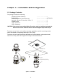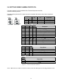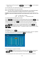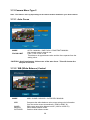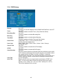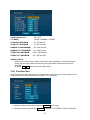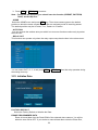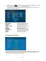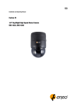
1
SD535DWA
Warnings and Cautions
WARNING
TO REDUCE THE RISK OF FIRE OR ELECTRIC SHOCK, DO NOT EXPOSE THIS PRODUCT TO RAIN
OR MOISTURE. DO NOT INSERT ANY METALLIC OBJECTS THROUGH THE VENTILATION GRILLS OR
OTHER OPENINGS ON THE EQUIPMENT.
CAUTION
EXPLANATION OF GRAPHICAL SYMBOLS
The lightning flash with arrowhead symbol, within an equilateral triangle, is intended to
alert the user to the presence of uninsulated "dangerous voltage" within the product's
enclosure that may be of sufficient magnitude to constitute a risk of electric shock to
persons.
The exclamation point within an equilateral triangle is intended to alert the user to the
presence of important operating and maintenance (servicing) instruction in the literature
accompanying the product.
II
FCC COMPLIANCE STATEMENT
FCC INFORMATION: THIS EQUIPMENT HAS BEEN TESTED AND
FOUND TO COMPLY WITH THE LIMITS FOR A CLASS A DIGITAL DEVICE,
PURSUANT TO PART 15 OF THE FCC RULES.
THESE LIMITS ARE
DESIGNED TO PROVIDE REASONABLE PROTECTION AGAINST HARMFUL
INTERFERENCE WHEN THE EQUIPMENT IS OPERATED IN A COMMERCIAL
ENVIRONMENT. THIS EQUIPMENT GENERATES, USES, AND CAN RADIATE
RADIO FREQUENCY ENERGY AND IF NOT INSTALLED AND USED IN
ACCORDANCE WITH THE INSTRUCTION MANUAL, MAY CAUSE HARMFUL
INTERFERENCE TO RADIO COMMUNICATIONS.
OPERATION OF THIS
EQUIPMENT IN A RESIDENTIAL AREA IS LIKELY TO CAUSE HARMFUL
INTERFERENCE IN WHICH CASE THE USER WILL BE REQUIRED TO
CORRECT THE INTERFERENCE AT HIS OWN EXPENSE.
CAUTION: CHANGES OR MODIFICATIONS NOT EXPRESSLY APPROVED
BY THE PARTY RESPONSIBLE FOR COMPLIANCE COULD VOID THE USER'S
AUTHORITY TO OPERATE THE EQUIPMENT.
THIS CLASS A DIGITAL APPARATUS COMPLIES WITH CANADIAN ICES-003.
CET APPAREIL NUMÉRIQUE DE LA CLASSE A EST CONFORME À LA NORME
NMB-003 DU CANADA.
CE COMPLIANCE STATEMENT
WARNING
THIS IS A CLASS A PRODUCT. IN A DOMESTIC ENVIRONMENT THIS
PRODUCT MAY CAUSE RADIO INTERFERENCE IN WHICH CASE THE USER
MAY BE REQUIRED TO TAKE ADEQUATE MEASURES.
CAUTION
DANGER OF EXPLOSION IF BATTERY IS INCORRECTLY REPLACED.
REPLACE ONLY WITH THE SAME OR EQUIVALENT TYPE.
III
IMPORTANT SAFEGUARDS
1. Read these instructions.
2. Keep these instructions.
3. Heed all warnings.
4. Follow all instructions.
5. Do not use this apparatus near water.
6. Clean only with dry cloth.
7. Do not block any ventilation openings. Install in accordance with the manufacturer’s instructions.
8. Do not install near any heat sources such as radiators, heat registers, stoves, or other
apparatus (including amplifiers) that produce heat.
9. Do not defeat the safety purpose of the polarized or grounding-type plug. A polarized plug has
two blades with one wider than the other. A grounding type plug has two blades and a third
grounding prong. The wide blade or the third prong are provided for your safety. If the provided
plug does not fit into your outlet, consult an electrician for replacement of the obsolete outlet.
10. Protect the power cord from being walked on or pinched particularly at plugs, convenience
receptacles, and the point where they exit from the apparatus.
11. Only use attachments/accessories specified by the manufacturer.
12. Use only with the cart, stand, tripod, bracket, or table specified by
the manufacturer, or sold with the apparatus. When a cart is used,
use caution when moving the cart/apparatus combination to avoid
injury from tip-over.
13. Unplug this apparatus during lightning storms or when unused for
long periods of time.
14. Refer all servicing to qualified service personnel. Servicing is required when the apparatus has
been damaged in any way, such as power-supply cord or plug is damaged, liquid has been
moisture, does not operate normally, or has been dropped.
15. CAUTION – THESE SERVICING INSTRUCTIONS ARE FOR USE BY QUALIFIED SERVICE
PERSONNEL ONLY. TO REDUCE THE RISK OF ELECTRIC SHOCK DO NOT PERFORM
ANY SERVICING OTHER THAN THAT CONTAINED IN THE OPERATING INSTRUCTIONS
UNLESS YOU QRE QUALIFIED TO DO SO.
16. Use Certified/Listed Class 2 power source only.
17. Apparatus shall not be exposed to dripping or splashing and no object filled with liquids, such as
vases, shall be placed on the apparatus.
IV
Table of Contents
Chapter 1 — Introduction ............................................................................................. 1
1.1 Features............................................................................................................................. 1
Chapter 2 — Installation and Configuration ............................................................... 3
2.1 Package Contents............................................................................................................. 3
2.2 Configuration of Fastrax IV Dome Camera System....................................................... 4
2.3 Setting Dome Camera Termination................................................................................. 6
2.4 Fail-safe Network .............................................................................................................. 7
2.5 Setting Dome Camera Address (ID) ................................................................................ 8
2.6 Setting Dome Camera Protocol....................................................................................... 9
2.7 Connections .........................................................오류! 책갈피가 정의되어 있지 않습니다.
• Connecting to the RS485/ 422 .......................................................................................................10
• Connecting Video out connector ..................................................................................................10
• Connecting Alarms .........................................................................................................................10
• Connecting the Power ....................................................................................................................10
2.8 Getting Started................................................................................................................ 11
Chapter 3 — Program and Operation........................................................................ 12
3.1 Dome Camera Selection................................................................................................. 12
3.2 Accessing the On-Screen Menu Utility......................................................................... 12
3.3 How to control the On-Screen Menu Utility.................................................................. 12
3.4 Auto Scan (Shortcut: SCAN) ......................................................................................... 13
3.5 Preset (Shortcut: PRST) ................................................................................................ 16
3.5.1 Event Function ........................................................................................................................19
3.5.2 Motion.......................................................................................................................................19
3.5.3. Tracking ...................................................................................................................................21
3.5.4 Cross ........................................................................................................................................22
3.5.5 Enter .........................................................................................................................................24
3.5.6 Abandon ...................................................................................................................................24
3.5.7 Removal ...................................................................................................................................25
3.6 Shortcut of Preset Program........................................................................................... 26
3.7 Tour (Shortcut: TOUR) ................................................................................................... 27
3.8 Pattern (Shortcut: PTRN) ............................................................................................... 29
3.9 Alarm................................................................................................................................ 30
V
3.10 Schedule........................................................................................................................ 32
3.11 Event History................................................................................................................. 33
3.12 Camera Menu Type 1.................................................................................................... 34
3.12.1 Auto Focus.............................................................................................................................34
3.12.2 WB (White Balance) Control ................................................................................................34
3.12.3 Auto Exposure.......................................................................................................................35
3.12.4 DIS (Digital Image Stabilization) ..........................................................................................36
3.12.5 Camera Setup ........................................................................................................................37
3.13 Camera Menu Type 2.................................................................................................... 38
3.13.1 Auto Focus.............................................................................................................................38
3.13.2 WB (White Balance) Control ................................................................................................38
3.13.3 Auto Exposure.......................................................................................................................39
3.13.4 DIS (Digital Image Stabilization) ..........................................................................................40
3.13.5 Camera Setup ........................................................................................................................41
3.14 OSD Setup .................................................................................................................... 42
3.15 Privacy Zone ................................................................................................................ 44
3.16 Time & Date Setup ....................................................................................................... 45
3.17 Home Function Setup.................................................................................................. 45
3.18 View Angle.................................................................................................................... 46
3.19 Origin Offset................................................................................................................. 48
3.20 Dome Reset .................................................................................................................. 49
3.21 System Menu................................................................................................................ 50
3.22 Function Run................................................................................................................ 51
3.23 Initialize Data................................................................................................................ 52
3.24 System Information ..................................................................................................... 53
Appendix A — Specifications .................................................................................... 54
Appendix B — Troubleshooting ................................................................................ 56
Appendix C — Glossary ............................................................................................. 57
Appendix D — Short Cut Key..................................................................................... 60
VI
Chapter 1 — Introduction
1.1 Features
The Fastrax IV dome camera and the keyboard controller make up the building blocks for
any surveillance/security system. Using multiple Keyboard Controllers and multiple dome
cameras, no place is too large for monitoring. Extensible and flexible architecture facilitates
remote control functions for a variety of external switching devices such as multiplexers and
DVRs.
• Built-in optical power zoom camera with True Night Shot function.
• 240 Preset positions (Individual AE and Event).
• 8 Tours consist of Preset, Pattern, Auto-Scan and other Tours can be programmed with
over 300 functions and Preset location. While moving, each Preset scan can be watched in
smooth Vector Scan mode.
• 16 Auto Scans with the normal, the vector, and the random mode and the Endless AutoPan with 13 speed steps.
• 8 Patterns (up to 500 second) and 8 Privacy zones.
• Motion Detection (Bounding Box, Trace)
• Auto Tracking and Cross Tracking.
• Video Analytics Function (Cross, Enter, Abandon and Removal).
• DIS (Digital Image Stabilization) Function.
• Function Scheduling.
• 16 Area Titles.
• 8 Alarm inputs / 4 Aux outs (NC & NO).
• Variable speed from 0.1°/sec to 380°/sec.
Three Variable speed (SLOW, NORMAL, TURBO)
Turbo speed is Max 380°/sec with Ctrl key pressed.
• Pan / Tilt speed is inversely proportional to the zoom ratio with the option.
• Maximum speed is 380°/sec when preset command.
• Auto Calibration from 0.1° to 6° (Tilt range is 0° to 180°).
• Programmable user preferences (alarm, preset, title, etc.).
• 180° Digital Flip or 90° Auto Flip depended on the model.
• Up to 999 selectable camera addresses (3999 by software setting).
• Multi-language Menu Display, Password Confirmation.
• Function Run menu using DVR without function key (Pattern, SCAN,..)
• Coaxial Communication with Coaxitron of Pelco & Fastrax
• Built-in RS-485/422 receiver driver.
• Optional Clear bubble with black liner (shelter) for concealing the camera.
1
• Optional Tinted Bubble, Indoor & Outdoor pendant housing with heater & blower, Indoor
Flush mount, Parapet mount & Roof Top mount.
Figure 1 – Typical System Configuration
push
bubble ring ass'y
remove camera window
screw
push
remove window
assemble bubble ring ass'y
Figure 2 –Assemble bubble ring ass’y (Optional)
Note : It is recommended to remove camera window for improving picture quality
when you use bubble ring ass’y.
CAUTION : When installing a Fastrax dome on a high pole outside, caution should be
taken to avoid vibration and shaking of Fastrax dome due to windload or
shock of passing heavy vehicles. If pole is not stable enough, it may
cause malfunction in accurate tilt positioning.
2
Chapter 2 — Installation and Configuration
2.1 Package Contents
The package contains the following.
Fastrax IV (Dome Camera)
Bubble Ring
Instruction Manual (This Document)
Assembly Screws for Attaching Fastrax IV
Plastic Anchor
10Pin Connector
12Pin Connector
………………………1
………………………1(Optional)
………………………1
………………………3
………………………3
………………………1
………………………2
CAUTION : Be sure to have caution labels (E version only) on both the body and the
base of the camera. Different version will not support input and output.
The dome camera is for use in surface mounting applications and the mounting surface
should be capable of supporting loads up to 10lb (4.5kg).
The dome camera’s base should be attached to a structural object, such as hard wood,
wall stud or ceiling rafter that supports the weight of the dome camera.
CABLE ENTRY
SURFACE(CEILING)
Unlock
Lock
BASE
Align extruded tap in the base to
the Keyhole on the pcb in the body
Lock
BODY
Figure 3 – Installation
3
2.2 Configuration of Fastrax IV Dome Camera System
Figure 4 – Basic installation diagram
4
The Fastrax IV Dome Camera may be used in a Pelco coaxitron controlled system with all
functions and capabilities available.
For control the transmission mode you should be following Step:
1. Adjust the ID(DIP switch)*. Device ID should be the same as Camera ID.
2. Adjust the protocol(DIP switch)*. Device protocol should be the same as Camera protocol.
3. Connect the keyboard RS485 port to the device RS485 port.
4 . Connect the camera video output port to the device video input port (BNC).
5. Connect the device video output port to the monitor (BNC).
The dome camera must be installed by qualified service personnel in accordance with all
local and federal electrical and building codes. The system should be installed according to
Figures 4 through 10.
5
Figure 6 – Layout of Switches
2.3 Setting Dome Camera Termination
The device which is connected at end of line, whether it be a dome camera or keyboard
controller, must have the cable for communication terminated by setting the appropriate DIP
switch. Without proper termination, there is potential for control signal errors. Total length of
the cable for communication should not exceed 4000ft (1.2km).
on
SW1
SW1
SW1-1
SW1-2
Terminated
ON
ON
Not terminated
OFF
OFF
Figure 7 – Setting Dome Camera Termination
6
2.4 Fail-safe Network
When you control the dome by the other device not own keyboard, some error may be
existed in the serial communication. The reason is caused by the other device without the
fail-safe network.
At this time, you solve the problem to set this DIP switch to ON of the nearest dome from the
other device only.
on
SW1
SW1
SW1-3
SW1-4
ON
PULL-UP
PULL-DOWN
OFF
NONE
NONE
Figure 8 – Setting Dome Camera Termination
Figure 9- Termination Diagram
7
2.5 Setting Dome Camera Address (ID)
To prevent damage, each dome camera must have a unique address (ID). When installing
multiple dome cameras using a multiplexer, it is suggested that the dome camera address
match the multiplexer port number.
If you want to set the address more than 999, you should contact the service provider.
Example: Port 1 = Dome 1, Port 2 = Dome 2 … Port 16 = Dome 16. If more than 16 dome
cameras are installed using two or more multiplexers, ID of the dome camera should be ID of
MUX x No. of camera IN. (e.g. multiplexer ID= n, Camera IN= m then ID of Dome =16x
(n-1)+m )
1
8
1
23
45 6
S3
0
0
.
9
S2
0
0
.
9
9 01
78
23
S1
DOME ID
1
2
.
999
8
45 6
9 01
78
S2
1
45 6
23
S3
9 01
78
8
Refer to Figures 4-5 for setting the dome camera address (ID) and protocol selection.
Figure 10- Setting Dome Camera Address (ID)
8
S1
1
2
.
9
2.6 SETTING DOME CAMERA PROTOCOL
If a dome camera is to be installed with a Fastrax keyboard controller,
select the default protocol.
Consult service personnel if a dome camera is installed with device other than a keyboard
controller.
NTSC
S/W
D1
S4-1
D2
S4-2
D3
S4-3
D4
S4-4
on
on
PAL
S4
On
Enable
PAL
Off
Disable
NTSC
RS-422
RS-485
FUNCTION
Alarm
NTSC/PAL
Reserved
RS-422/RS-485
S4
D5
S5-1
Off
Off
Off
Off
On
On
On
On
Off
Off
Off
Off
D6
D7 D12
S5-2 S5-3 S6-4
Off
Off
Off
Off
On
Off
On
Off
Off
On
On
Off
Off
Off
Off
Off
On
Off
On
Off
Off
On
On
Off
Off
Off
On
Off
On
On
On
Off
On
On
On
On
D8
S5-4
Off
Off
Off
Off
On
D9
D10
S6-1 S6-2
Off
Off
Off
On
On
Off
On
On
Off
Off
D11
S6-3
Off
On
PROTOCOL
F2,F2E,Pelco-D,Pelco-P:default
F2,F2E
Sensormatic RS422
Pelco-D, Pelco-P
Vicon
Ernitec
Reserved
F2
Philips(Bosch)
Reserved
Dynacolor
Reserved
BAUD RATE
2400 bps
4800 bps
9600 bps (Default)
19200 bps
38400 bps
PARITY BIT
None
Even
Figure 11 – Protocol Selection Switches
Note : When used in a Pelco coaxitron control system the default protocol setting should be used.
9
2.7 Connections
• Connecting to the RS485/ 422
The dome camera can be controlled remotely by an external device or control system,
such as a control keyboard, using RS485 half-duplex, RS422 full duplex or simplex serial
communications signals. Connect Marked Tx+, Tx- to Tx+(Rx+) and Tx-(Rx-) of the RS485
control system.
If control system is RS422, connect Rx+(Tx+), Rx+(Tx-) and Rx+, Rx- of the dome camera to
Rx+, Rx- and Tx+, Tx- of the control device respectively.
If using a coaxitron control system the RS485/422 connection is not necessary. All control
signals are carried through the coaxial cable along with the video signal.
• Connecting Video out connector
Connect the video out(BNC) connector to the monitor or video input.
• Connecting Alarms
AL1 to 8 (Alarm In)
You can use external devices to signal the dome camera to react on events. Mechanical or
electrical switches can be wired to the AL (Alarm In) and GND (Ground) connectors.
See Chapter 3 — Program and Operation for configuring alarm input.
GND (Ground)
NOTE: All the connectors marked GND are common.
Connect the ground side of the Alarm input and/or alarm output to the GND connector.
NC(NO)1 TO 4 (Normal Close or Normal Open : Alarm Out)
The dome camera can activate external devices such as buzzers or lights. Connect the
device to the NC(NO) (Alarm Out) and COM (Common) connectors.
See Chapter 3 — Program and Operation for configuring alarm output.
• Connecting the Power
Connect the power of AC 24V 850mA to the dome camera.
Use certified / Listed Class 2 power source only.
10
2.8 Getting Started
Once installed apply power to the dome camera. The dome camera will start a configuration
sequence.
TIME and DATE
PRESET TITLE
AREA TITLE
FUNCTION
UNDER RUNNING
001
2010/01/22 AM 10:18:45
AF AE
EMPTY DATA
INFORMATION
DISPLAY
STATUS of
FOCUS and AE
CAMERA TITLE
CAMERA ID
ALARM:1
DOMEID:0001
W→360.0,090.0 X02
ALARM DISPLAY
PAN , TILT ANGLE
and Zoom
VIEW DIRECTION
OSD Position
The dome can move the OSD position in the OSD position setup.
2010/01/22 AM 10:18:45
(AREA TITLE)
(AF AE)
(FUNC TITLE )
(CTRL KEY TO MOVE)
SAVE AND EXIT(ESC TO CANCEL)
(ALARM MESSAGE)
(DOME ID…)
(ANGLE…)
OSD Position Setup
11
Chapter 3 — Program and Operation
3.1 Dome Camera Selection
Before you program or operate a dome camera, you must select the dome camera by
pressing the dome camera No. + CAM
Example: Pressing 1 , 0 and CAM key sequentially will select dome camera 10. The
selected dome camera ID will be displayed on the LCD monitor of the keyboard controller.
3.2 Accessing the On-Screen Menu Utility
You can call up the On-screen menu utility on your monitor by pressing MENU key on the
keyboard controller, the following On-screen menu utility will appear:
3.3 How to control the On-Screen Menu Utility
Function
Button
Call the On-screen menu utility
MENU
Navigate through the menu items.
Joystick up or down
Go into the sub-menu items.
Zoom handle twist
Change value.
Enter the editing title mode.
Joystick left or right or
Zoom handle twist
Change value of angle
CTRL + Joystick
Enter the changing angle mode.
IRIS Open
Exit the changing angle mode.
IRIS Close
Escape (EXIT)
ESC
12
3.4 Auto Scan (Shortcut: SCAN)
The Auto scan supports up to 17 programmed angles at user-programmable speeds.
NUMBER : 01 -08, 10-17, 09:AUTO PAN mode
TITLE
: up to 12 characters.
MODE
: NORMAL, VECTOR, RANDOM (AUTO PAN Mode: NORMAL, RANDOM only)
NORMAL : Move from start point to end point in panning only.
VECTOR : Move from start point to end point including tilt and zoom simultaneously and
linearly. In some model, the zoom is fixed at wider angle and the zoom
magnification information is not displayed.
RANDOM : Move randomly between the start point and the end point.
SCAN DIR
SWAP
START ANGLE
END ANGLE
SPEED
DWELL
: Set the scan direction, CCW (Counter Clock Wise), CW (Clock Wise)
: Swap the start point for the end point.
: Set the start angle.
: Set the end angle.
: 1 - 17 steps, the lower number means the slower speed.
: Set the dwell time at the both end, 01 – 99 seconds
Follow these steps to program Auto Scan:
1. Press the SCAN key to enter the auto scan menu directly. Or press the MENU key to
display the main menu on the monitor. Scroll to Auto Scan and then twist the Joystick .
2. Select the” NUMBER” and set the desired number by pushing the Joystick left or right.
3. Select the “TITLE” and twist the Joystick to enter the title edit mode.
4. Select the “ ^ “ to the characters table(an upper case & lower case) or select the “ < “ to
delete at the desired character then the cursor position moves to the left. Or select the “X”
to delete the desired character without move. Push the Joystick left or right at the “Exit”
field to finish title edit menu without save or select the “OK” to finish title edit menu with
save.
13
5. Select “MODE”.
6. Set “Scan Direction” to CCW or CW.
7. Select “SWAP” Set to ON, to exchange the start angle and the end angle.
8. Select “Start Angle” and Push the Joystick left or right. Hold down the CTRL key while
selecting the start position using the Joystick. Current panning position will be displayed.
Release CTRL key to complete the selection of the start position. Or press IRIS Open
then the “CTRL” displays. Move the desired position and the zoom position.
Press IRIS Close then the “CTRL” disappears. To adjust at the 0.1 degree interval, twist
the Joystick at the pan field and the tilt field. To adjust at the one zoom interval, twist the
Joystick at the zoom field. Push the Joystick left or right at the “Exit” field to finish “auto
scan start angle” menu.
9. Select “End Angle.” and Push the Joystick left or right. Hold down the CTRL key while
moving the Joystick to select the end position. The end position angle should be larger
than start position. Release the CTRL key to complete the selection of the end position.
Or press IRIS Open then the “CTRL” displays. Move the desired position and the zoom
position. Press IRIS Close then the “CTRL” disappears. To adjust at the 0.1 degree
interval, twist the Joystick at the pan field and the tilt field. To adjust at the one zoom
interval, twist the Joystick at the zoom field. Push the Joystick left or right at the “Exit”
field to finish “auto scan end angle” menu.
10. Select “SPEED”.
11. Set “DWELL TIME”.
12. Select Save and Exit and push the Joystick to the right or press IRIS Open. Press
ESC or IRIS Close to exit the program without saving.
Pressing the HOME key delete stored data at the angle field.
To set the position using the preset position:
a. Before entering the Auto Scan menu, select a preset position as a starting point for
Auto Scan.
Example: 2 + PRST and do step 1 to 7. In step 8, just press the Ctrl key at the start angle
position, the current position will be displayed as a start position.
14
b. Save and exit from the menu.
c. In normal mode, call a preset to be the end point of scan. Press 3 + PRST then press
Scan key to enter the Auto Scan menu. Move the cursor position to END ANGLE. Just
press CTRL key at the end angle position. Save and exit from the menu.
The setting procedure is the same as above.
Note : 09: AUTO-PAN mode (Endless panning)
15
3.5 Preset (Shortcut: PRST)
If you need to view specific places routinely, you should program presets. A preset is a
programmed video scene with automatic pan, tilt, zoom, focus, and AE settings. Once
programmed, placing the number position and pressing a PRST button on your controller
calls up that preset automatically. In addition, presets may be assigned to alarm actions or
as the “home” position for the dome camera. As many as 240 presets, whose positions are
saved in the dome’s firmware, may be programmed.
Number
Title
Dwell Time
: 001 -240,
: up to 12 characters.
: Set the dwell time at the both end, 01 – 99 seconds
Focus
: Auto, Manual, One Push
Auto
: Auto Focus at continuous.
Manual : Camera goes into manual mode
One Push : Held the auto focus at one times only with a pan/tilt/zoom action occurred.
Preset Position
Event Function
Auto Exposure
Preset List
: Set the preset position with view direction and lens control..
: Set the desired function.
: Set the auto exposure of the desired preset..
: Show the stored preset list.
Follow steps below to store the Preset positions:
1. Press the PRST key to enter the preset menu directly. Or press the MENU key to display
the main menu on the monitor. Scroll to preset and push the Joystick to the right.
2. Select the “Number” and select the preset position to be stored by pushing the Joystick
up, down, right, or left.
3. Follow the procedure of the auto scan above to edit titles.
4. If selected preset number is not empty, “Already exist preset” message will be displayed
on the monitor and select the “OK” and push the Joystick to the right to overwrite.
16
5. After selecting a preset position, press and hold CTRL, Use the Joystick to control the
direction of the camera and lens.
6. After aiming the camera (view direction and lens control), release CTRL.
7. Select “Event Function” and pushing the Joystick left or right. Then the event function
setup displays.
* Please refer to the below ( 3.5.1 Event Function) for more details.
17
8. Set the “Auto Exposure”
Refer to the AE SETUP in the camera setup.
9. Repeat steps 2 through 8 for each additional preset position.
10. Select Save by pushing the Joystick to the right. Press Cancel to exit the Preset menu
without saving.
11. Select the preset list, then the stored preset list displays.
Select the desired preset then the desired preset setup displays.
Note : Press the HOME key at desired preset in preset table to delete a programmed preset .
18
3.5.1 Event Function
You can set a preferred function in specified preset position.
All available functions are like below.
Motion
Tracking
Cross
Enter
Abandon
Removal
Function
Output
Hold Time
: You can detect a moving object in specified preset position.
: You can make a camera follow the moving object automatically (In case of
catching more than 1 moving objects at the same time, a bigger object will be
tracked).
: You can detect a moving object crossing a specified virtual line in a preset
position.
: You can detect a moving object that newly enters in a specified area
(enter box).
: You can detect an object abandoned in a specified area.
: You can detect an object removed in a specified area..
: Choose a function (None, Motion, Tracking, Cross, Enter, Abandon,
Removal).
: Set the alarm output. (Off, Out1~Out4)
: Set the hold time of alarm signal for chosen function, (Off, 03 – 99 seconds)
3.5.2 Motion
You can detect moving objects in specified preset position.
You can see the results by either “Bounding Box” or “Trace”.
As a result of motion, screen will display the bounding box or trace.
(“Bounding box” means you can see a virtual rectangle on moving object. In prior of this, you
make sure that you set “On” in display and Bounding box in OSD Setup.
“Trace” means you can see a trace on moving object. In prior of this, you make sure that you
set “On” in display and Bounding box in OSD Setup.)
19
Sensitivity
: Set the sensitivity step. 1-8 step, the lower number means the lower
sensitivity (dull).
Object Size
: Set the min/max size.
Exclusion Area : Set the exclusion area.
Note : If you change the sensitivity value, it will automatically be applied to the other
video analytic functions.
Follow steps as below to set the Motion Detection:
1. Select the function in the event function. Scroll to Motion and push the Joystick to the
right.
2. Select the “Sensitivity” and Set the object size..
3. Select “Exclusion Area”.
(Viewing image will be positioned to the selected preset automatically when user enter this
Menu)
20
Exclusion Area:
You can set inactive area of Motion detection on this Menu.
To avoid false alarm, we recommend you to exclude areas like trees with swaying branches
or street with walking people.
Set Area
Clear Area
All Set
All Clear
: Locate the cursor on the “Set Area” and then twist Joystick and then move
Green grid to the position. Change the color of grid to disable Motion
Detection by twisting Joystick. Then disabled Grid will be changed to Yellow
color. (Default color of grid is Blue)
: Locate the cursor on the “Clear Area” and then twist Joystick and then
move Green grid to the position. Change the color of grid to enable Motion
Detection by twisting Joystick. Then enabled grid will be changed to Blue
color.
: Select All grids and change to Motion Detection disabled grid.
: Select All grids and change to Motion Detection enabled grid.
Note : We recommend setting Exclusion Areas for certain zones with unwanted
motion. (For example, swaying branches or leaves of tree, flickering monitor screen)
3.5.3. Tracking
You can make a camera follow the moving object automatically (In case of catching more
than 1 moving objects at the same time, a bigger object will be tracked)
Zoom Enable
Return Time
Lost Mode
: Set to enable or disable linked zoom capability during tracking.
: Set the dwell time before move to previous position once tracking is
inactive. (Off, 3~99 seconds.)
: Choose “Stop” or “Zoom Out” when object has been lost.
21
Stop
: Stop Tracking in current position when object lost.
Zoom Out : “Zooming Out” will be activated in 3 seconds after object was lost.
However this can not work if you switched off “Zoom Enable”.
Object Size
: Set the min/max size.
Exclusion Area
: Set the exclusion area.
View Angle Limit
: Set to enable or disable limits of view angle during tracking.
On
: Enable limits of view angle only during tracking.
Off
: Enable limits of view angle during tracking always.
Right Limit
: Set 0.0 ~ 359.9
Left Limit
: Set 0.0 ~ 359.9
High Limit
: Set 0.0 ~ 180.0
Low Limit
: Set 0.0 ~ 180.0
Follow steps as below to set the Tracking:
1. Set the Zoom Enable.
2. Set the lost mode.
3. Select the object size and the exclusion area.
Follow the procedure of the detection above to the object size and the exclusion area.
4. Select the Exit (with saving) and push the Joystick to the right. Press ESC to exit the
program without saving.
Note : If you set to the sensitivity of tracking, select the motion in event function. Then
set to the sensitivity of motion. Select to the tracking in event function again.
Note : Auto tracking will be activated with an indicator (+) focused on the center of the
object
Note : Malfunctions in Auto Tracking might occur for the following cases:
- The object brightness is almost identical to the background luminance or in
environments with extreme low light conditions
- Water drop or damp on the Dome’s Bubble
- An environment with extreme changes in illumination
- An environment where there is excessive other non-target movement
- An environment where there is extreme twinkling or lambency on the object
- Movement too close to the camera optical axis
- Movement of the target in the vicinity directly below the camera
- Target movement that is very fast or very slow
- When the moving objects are either large or small in comparison to the
preconfigured object size
- When the camera is unsteady due to improper installation
3.5.4 Cross
You can detect a moving object crossing a specified virtual line (cross line) in a watch area.
You can see current status of moving object by “Bounding Box”.
22
(“Bounding box” means you can see a virtual rectangle on moving object. In prior of this, you
make sure that you set “On” in display and Bounding box in OSD Setup)
Min.
: Set the min size of object while object crossed.
Max.
: Set the max size of object while object crossed.
Direction
: Set the direction while object cross.
CW : CW (Clock Wise)
CCW : CCW (Counter Clock Wise)
Both : CCW (Counter Clock Wise), CW (Clock Wise),
Tracking
: Set the tracking use while object crossed.
Set Point
: Set the cross line.
Clear
: Remove the cross line.
Follow steps as below to set the Cross:
1. Set the min size of the enter object and set the max size.
2. Select the cross direction.
3. Select the tracking use while object crossed.
4. Select the “Set Point” for cross line.
Use the Joystick to set the location of the start point(yellow mark). Move the cursor (green
mark) by pushing the Joystick, up, down, right or left. Select the location of the end point.
Draw a cross line to end point from start point.
5. Select the Exit (with saving) and push the Joystick to the right. Press ESC to exit the
program without saving.
Note : To minimize failure rate of “Cross”, you are recommended to draw horizontal
Cross line than vertical line. Also cross line should be placed on the position where
object is passing fast.
23
Note : Malfunction might occur or the cross will be deactivated if the moving object
reaches the edge of the Cross-line.
3.5.5 Enter
This can detect a moving object that newly enters in a specified area (enter box).
You can see current status of moving object by “Bounding Box”.
(“Bounding box” means you can see a virtual rectangle on moving object. In prior of this, you
make sure that you set “On” in display and Bounding box in OSD Setup.
Min.
Max.
Base
: Set the min size of object while object entered.
: Set the max size of object while object entered.
: Set the reference point while object entered.
It occurs a event when reference point enters in a specified enter box.
Top
: Reference point is the top of object.
Bottom : Reference point is the bottom of object.
Both : Reference point is the top of object and bottom of object.
Set Point : Set the enter box.
Clear
: Remove the enter box.
Follow steps below to set the Enter:
1. Set the min size of the enter object and set the max size.
2. Select the enter base.
3. Select the “Set Point” for enter box.
4. Select the Exit (with saving) and push the Joystick to the right. Press ESC to exit the
program without saving.
3.5.6 Abandon
This can detect an object abandoned in a specified area.
You can see current status of moving object by “Bounding Box”.
Once moving object is fixed as “Abandon”, color of “Bounding box” will be changed to
complementary color of ROI line.
(“Bounding box” means you can see a virtual rectangle on moving object. In prior of this, you
make sure that you set “On” in display and Bounding box in OSD Setup.
24
Min.
Max.
Event Time
Set Point
Clear
: Set the min size of object while object abandoned.
: Set the max size of object while object abandoned.
: Set the event time.
10s,20s,30s,40s,50s,60s,70s,80s,90s,100s,120s,180s,240s
: Set the abandon box.
: Remove the abandon box.
Follow steps below to set the Abandon:
1. Set the min size of the enter object and set the max size.
2. Select the event time.
3. Select the “Set Point” then draw a box for two point.
4. Select the Exit (with saving) and push the Joystick to the right. Press ESC to exit the
program without saving.
Note : There might be malfunction of Removal for the following cases:
- The object brightness is almost identical to the background luminance
- When the objects are either large or small in comparison to the preconfigured
Object size
- Environments where there is strong direct/indirect light shining onto the object or
Background
- The abandoned object is not fixed.
3.5.7 Removal
This can detect a object removed in a specified area.
You can see current status of moving object by “Bounding Box”.
Once moving object is fixed as “Removal”, color of “Bounding box” will be changed to
complementary color of ROI line.
(“Bounding box” means you can see a virtual rectangle on moving object. In prior of this, you
make sure that you set “On” in display and Bounding box in OSD Setup.
25
Min.
: Set the min size of object while object removed.
Max.
: Set the max size of object while object removed.
Event Time : Set the event time.
Set Point : Set the area for removal.
Clear
: Remove the area.
Follow steps below to set the Removal:
1. Set the min size of the enter object and set the max size.
2. Select the event time.
3. Select the “Set Point”, then draw a box for two point.
4. Select the Exit (with saving) and push the Joystick to the right. Press ESC to exit the
program without saving.
Note : There might be malfunction of Removal for the following cases.
- The object brightness is almost identical to the background luminance
- When the objects are either large or small in comparison to the preconfigured
Object size
- Environments where there is strong direct/indirect light shining onto the object or
Background
3.6 Shortcut of Preset Program
After selecting the desired scene, press No. (1 to 240), and press CTRL and PRST
subsequently. The current view will be stored to the selected preset number if the preset
number is empty. If selected preset number is not empty, “Do you want to overwrite preset?”
message will be displayed on the monitor and select the “OK” and push the Joystick to the
right to overwrite.
Example: 1 , 0 , 1 + CTRL + PRST will store current view as preset No. 101. In this case,
focus will be programmed as Auto, dwell time will be set to 3 second, and the current AE
mode will be programmed.
26
3.7 Tour (SHORTCUT: TOUR)
There are 8 programmable Tours. Each Tour consists of up to 42 Preset positions, Patterns,
Scans or other Tours (second-level). Using second-level tours, it can be expanded to over
300 functions in a single tour.
Number
: 01 -08
Title
: up to 12 characters.
Scan Type : Normal, Vector
Normal : Move from start point to end point in panning only.
Vector : Move from start point to end point including tilt and zoom simultaneously and
linearly. In some model, the zoom is fixed at wider angle and the zoom
magnification information is not displayed.
Speed
: 1 - 13 steps, the lower number means the slower speed.
Event Enable : ON / OFF
ON : Enable all events except abandon and removal preconfigured in preset.
OFF : Disable all events preconfigured in preset.
Tour List
: Display the stored function list (Preset, Pattern, Auto Scan, Tour List) or
you will set the desire function list.
Follow the steps below to program the Tours:
1. Press MENU to display the main menu on the monitor. Scroll to Tour and push the
Joystick to the right to enter the Tour menu. Or just press the TOUR key on the
keyboard.
2. Select the” NUMBER” and set the desired number by pushing the Joystick left or right.
3. Select the “Scan Type” and if you have to choose vector type then you will apply the
speed.
4. Select the “Tour List”, then display the tour list..
27
Dwell
: Set the dwell time at the both end, 01 – 99 seconds
5. Blank position mark (---) will be displayed and selected, then twist the Joystick.
To add functions, select the preset, tour, pattern, and auto scan respectively.
6. You can also overwrite the programmed number and to remove a stored number from
the Tour, press the HOME key on the stored number, a blank position mark (---) will be
displayed.
7. Repeat Step 2 through 5 for each desired position. Each title will be displayed on top of
the line.
8. To edit the title, follow the procedure of the auto scan above to edit titles
28
9. Select Save and Exit and push the Joystick to the right. Press ESC to exit the program
without saving.
You can expand the Tour sequence by calling other programmed tours.
Note : The speed applies in the vector mode only.
Note : In the Tour mode, in conjunction with preset and Auto Scan, you can make the camera
travel from a preset position to another preset position at a specific speed.
Example: Preset 001>002>003>004>005>006, Auto Scan 01 starts at preset 002, ends at
preset 003, Auto Scan 02 starts at preset 005, ends at preset 006; Tour 001, 002, A01, 004,
A02.
1 Î 2 2~3 Î 4 Î 5~6, repeat
where Î : Quick move, ~ : Programmed speed
To change the dwell time of the preset in the tour:
Use the Joystick to move the cursor to a stored preset position. By pressing PRST key, the
camera will move to the stored Preset view and the cursor moves to the dwell time field. After
changing the dwell time, press PRST key and the cursor moves to the preset number.
To assign the functions other than preset in the tour when the function key is not existed:
Use the Joystick to move the cursor to a stored preset position. Pressing CTRL key or
IRIS OPEN key will change the preset number to other function (auto scan, pattern, tour,
preset) with the first programmed number. To change the number, twist the joystick or press
Tele or Wide key.
3.8 Pattern (Shortcut: PTRN)
The Pattern feature records user control of the selected dome camera. Up to four 8 patterns
can be stored and played back by pressing No.+ PTRN keys subsequently.
Follow steps below to program the Pattern:
1. Press MENU to display the main menu on the monitor. Scroll to Pattern and push the
Joystick to the right to enter the pattern menu. Or just press the PTRN key on the
keyboard.
2. To edit the pattern title, follow the procedure of the auto scan above to edit titles.
29
3. Select the desired pattern to be programmed by pushing the Joystick up or down. If the
“Sec” is not 000, a pattern has already been recorded. Patterns can be overwritten.
4. Select the desired pattern (Set) then twist the Joystick.
5. Display the “set pattern”.
6. Press and hold down the CTRL key while controlling the camera direction and zoom
with the Joystick. The dome will be automatically recorded until you release the CTRL
key. Or press IRIS Open then the “CTRL” displays. Move the position and the zoom
position. Press IRIS Close then the “CTRL” disappears.
7. Select Save and Exit and push the Joystick to the right. Press ESC to exit the program
without saving.
Note : Press the HOME key at any programmed position to delete the pattern.
Note : If total recording time reaches 500 seconds, it will automatically stop for a
moment.
3.9 Alarm
No
Priority
Function
In
Out
Hold
: Alarm input number
: The lower number has higher priority. (1-8)
: Stored function number to be called by alarm.
: NO/NC - normally open /Closed OFF - ignore
: OUT1~OUT4 - Relay out 1,2,3,4, OFF - No output.
: Alarm will be held for programmed time (03 to 99 seconds)
30
Latch
Dwell
: ON - Shows all alarms including past alarm.
OFF - Shows activated alarms only.
: means the dwell time during multiple alarms, 03 to 99 seconds.
There are 8 levels of priority. The function can be selected by Preset, Auto scan, Pattern or
Tour and “0” is the highest priority. Lower priority alarms won’t be serviced until the higher
priority alarm is completed. Equal priority alarms will be serviced repeatedly with the dwell
time.
The RELAY OUT setup is helpful when the outdoor housing is used with the dome.
Ex.) When you connect the relay output of the dome to the heater connector of the outdoor
housing, the relay output can operate during the setting time only.
Alarm: the relay output is operated during an alarm operation or by the short key of our
keyboard.
1-5 MIN (minute): the relay output is operated during this setting time only by the function
run of the dome menu or the short key of our keyboard.
Note : This 1-5 MIN setting is not operated by an alarm.
Note : If you disable Alarm by dip switch, Alarm menu will be displayed following
screen.
31
You can set the schedule of Alarm operation on this menu.
3.10 Schedule
You can set the schedule of Preset, Pattern, Tour, Auto Scan, Auto Pan, Origin, DIS On, DIS
Off on this menu.
Selected Function will be effective per selected start time and day (of the week) range.
Follow below steps to set schedule.
1. Locate cursor on the “+” and then, twist Joystick (keyboard) to add a new schedule.
2. To choose day (of the week) range, locate cursor on the relevant “Day” and then twist
Joystick (keyboard) to set one of 10 ranges.
(All, Mon, Tue, Wed, Thu, Fri, Sat, Sun, S-S, M-F)
3. To choose start time, locate cursor on the relevant “Start time” and then twist Joystick
(keyboard) to set time.
4. Choose one function to work on this schedule.
Note : In prior of this setting, the functions need to be set on menu.
Enable
Choose to enable or disable selected function.
32
X
<
>
Delete the relevant schedule.
Return to the previous page in the schedule list.
Return to the next page in the schedule list.
Note : Origin check in Schedule will not be activated when the camera is operating
under Auto Scan, Pattern, Tour and Event function per other schedule.
3.11 Event History
You can see list of Event (Alarm1, Alarm2, Alarm3, Alarm4, Alarm5, Alarm6, Alarm7, Alarm8,
Cross, Tracking, Abandon, Removal, Motion, Booting) on this menu.
This device can memorize 256 events at maximum.
(Over 256 events, the oldest event will be erased one by one)
<<
<
>
>>
Clear
Return to the first page in the history list.
Return to the previous page in the history list.
Proceed to the next page in the history list.
Proceed to the last page in the history list.
Delete all the information in the history list.
33
3.12 Camera Menu Type 1
Note : The features will vary depending on the camera module installed in your dome camera.
3.12.1 Auto Focus
MODE
AUTO / MANUAL / ONE PUSH / CONSTANT MANUAL
Use manual mode in normal use.
AF SENSITIVITY NORMAL / LOW
NORMAL: Use this option when shooting fast motion.
LOW : Offers better focus stability. In low luminance conditions, Auto
Focus stops operation even when brightness changes, enabling stable images of moving
objects.
FOCUS LIMIT
This distance is approximate value and the focus operate from the
setting value.
CAUTION : Avoid continuous, 24-hour use of the auto focus. This will shorten the
lifespan of the lens.
3.12.2 WB (White Balance) Control
MODE
AUTO / INDOOR / OUTDOOR / ONE PUSH / ATW / MANUAL /
OUTDOOR AUTO / SODIUM AUTO / SODIUM
34
AUTO
Computes the white balance value output using color information
from the entire screen automatically. (3000 to 7500 °K)
INDOOR
3200 K base mode
OUTDOOR
5800 K base mode
ONE PUSH
One push WB mode is a fixed mode that may be automatically
readjusted at the stop after moving.
ATW
Auto tracing white balance. (2000 to 10000° K)
MANUAL
Control of R and B gain
OUTDOOR AUTO Auto mode specifically for outdoors.
SODIUM AUTO
Auto mode that is compatible with sodium vapor lamps
SODIUM
Fixed mode specifically for sodium vapor lamps
RGAIN
BGAIN
0 ~ 255
0 ~ 255
RGAIN / BGAIN modes are controllable only in MANUAL Mode
3.12.3 Auto Exposure
MODE
AUTO
MANUAL
IRIS PRIO
SHUTTER PRIO
BRIGHT
IRIS
GAIN
SHUTTER
BRIGHT
BACK LIGHT
SLOW SHUTTER
NIGHT SHOT
Start Time
End Time
WDR
AUTO / MANUAL / IRIS PRIO / SHUTTER PRIO / BRIGHT
Auto Iris and Gain, Fixed Shutter speed
(NTSC: 1/60 sec, PAL: 1/50 sec)
Variable Shutter, Iris and Gain.
Variable Iris, Auto Gain and Shutter speed.
Variable Shutter speed, Auto Iris and Gain.
Variable Iris and Gain
F1.6 / F2 / F2.4 / F2.8 / F3.4 / F4 / F4.8 / F5.6 / F6.8 / F8 /
F9.6 / F11 / F14 / F16 / F19 / F22 / F28 / CLOSE
-3 DB / 0 / 2 / 4 / 6 …… / 28
1/1, 1/2, 1/3, 1/6. .. 1/3500, 1/6000, 1/10000
0, 1, 2, 3, 4 ..... 29, 30, 31
Objects in front of bright backgrounds will be clearer with BLC ON.
ON / OFF
AUTO, ON, OFF, GLOBAL, TIME
ON / OFF
Note : Values in ( ) are for PAL Camera.
35
Note : The Back Light operates in AUTO mode only.
For example, if you change the back light to ON, the camera will change AE mode to “AUTO”.
The NIGHT SHOT option removes the IR cutoff filter of the camera and makes the camera
sensitive to near infrared.
AUTO
Camera goes in to B&W mode at low light.
GLOBAL
Controlled by the keyboard.
The operator can enable NIGHT SHOT for all dome cameras at the same time.
If the NIGHT SHOT mode is set to GLOBAL, “999” + ENTER will turn Off the NIGHT
SHOT mode and “888” + ENTER will turn On the NIGHT SHOT mode.
ON
B/W mode.
OFF
Color mode.
START TIME
Set time to change from “Color mode” to “B/W mode”
END TIME
Set time to change from “B/W” to “Color mode”
Note : Selecting the Night Shot to Auto mode will change AE mode to “AUTO”.
3.12.4 DIS (Digital Image Stabilization)
DIS USE
IMAGE SHOW
NONE
PIP
PBP
ON / OFF
Choose to enable or disable DIS
NONE / PIP / PDP
Only viewing DIS Active image.
View original image (small) and DIS active image (big) as picture in
picture.
View original image (left) and DIS active image (right) as picture in
picture.
Note : There might be malfunction of DIS for the following cases.
- The camera is operating under extremely low light condition.
- The object brightness is almost identical to the background luminance
- The object is moving very fast
-. The camera is unsteady due to improper installation
Note : DIS will be deactivated if the camera is operating under Event function or
PAN/TILT/ZOOM/FOCUS commands.
36
3.12.5 Camera Setup
SHARPNESS
Digital ZOOM
IMAGE FLIP
The higher the value, the more edges in the picture will be
enhanced (0~15)
OFF: Zoom range is limited to the optical.
2X: Zoom is extendable up to 2x of digital range.
4X: Zoom is extendable up to 4x of digital range.
MAX: Zoom is extendable Max digital zoom range.
This function turns the video output from the camera upside down and
reverses it horizontally.
This option is helpful to install in the opposite side.
PRESET FREEZE
ON / OFF
ON
The image is frozen during calling preset.
BRIGHT OFFSET
-7,…,0(default),…7
Adjust the brightness level (AUTO, SHUTTER PRIO, IRIS PRIO mode
only)
SLOW RESPONSE
The slow response function allows you to lengthen the automatic exposure response speed
from 1 up to 32 times. For example, with the normal setting (about 1 second), if the
headlights of a car are caught by the camera, the camera automatically adjusts the exposure
so that it can shoot a high-intensity subject (in this case, the headlights). As a result, images
around the headlights, that is, the rest of the subject, except the headlights, becomes
relatively dark, and poorly distinguished. However, using the slow response function can still
easily distinguish the portions of the image surrounding the headlights.
DN THRESHOLD
5, … 18 (default),…, 28
Adjusts the level of light at which the camera automatically switches
out of night mode (B/W) operation.
STABILIZATION
ON/OFF, Image stabilizer
DNR
0~5, DNR filter effect level when pan/tilt stop
MOVING DNR
0~5, DNR filter effect level when pan/tilt move
GAIN LIMIT
4~15, Gain limit in the AE mode
37
3.13 Camera Menu Type 2
Note : The features will vary depending on the camera module installed in your dome camera.
3.13.1 Auto Focus
MODE
FOCUS LIMIT
AUTO / MANUAL / ONE PUSH / CONSTANT MANUAL
Use manual mode in normal use.
1.0M / 1.5M / 2.5M / 6.0M
This distance is approximate value and the focus operate from the
setting value.
CAUTION : Avoid continuous, 24-hour use of the auto focus. This will shorten the
lifespan of the lens.
3.13.2 WB (White Balance) Control
MODE
AWB
WAWB
INDOOR
OUTDOOR
AWB / WAWB / INDOOR / OUTDOOR / MANUAL
Computes the white balance value output using color information
from the entire screen automatically. (2500 to 9500 °K)
Wide range auto white balance mode. (1800 to 10500 °K)
Indoor white balance mode.
Outdoor white balance mode.
38
MANUAL
RGAIN
BGAIN
Manual mode. You can change R and B Gain manually
0 ~ 255
0 ~ 255
RGAIN / BGAIN modes are controllable only in MANUAL Mode
3.13.3 Auto Exposure
MODE
AE1
AE2
SHUTTER PRIO
MANUAL
SLOW SHUTTER
GAIN
BRIGHT
SHUTTER
FLICKERLESS
BACK LIGHT
WDR
WDR LEVEL
AE1 / AE2 / SHUTTER PRIO / MANUAL
Auto exposure mode1. (Use to normal surroundings: indoor)
Auto exposure mode2. (Use to high brightness surroundings: outdoor)
Variable Shutter speed, Auto Gain.
Variable Shutter speed, Gain.
ON / OFF
MIN / LOW / MID / HIGH
0, 1, 2, 3, 4 ..... 68, 69, 70
1/60(50), 1/100(120), …, 1/2000, 1/10000, 1/100000
ON / OFF
ON / OFF (NOTE: When ON, WDR will be disabled.)
ON / OFF (NOTE: When ON, BACKLIGHT will be disabled.)
10~50
Note : Values in ( ) are for PAL Camera.
Note : The Back Light operates in AUTO mode only.
For example, if you change the back light to ON, the camera will change AE mode to “AUTO”.
The NIGHT SHOT option removes the IR cutoff filter of the camera and makes the camera
sensitive to near infrared.
AUTO
Camera goes in to B&W mode at low light.
GLOBAL
Controlled by the keyboard.
The operator can enable NIGHT SHOT for all dome cameras at the same time.
If the NIGHT SHOT mode is set to GLOBAL, “999” + ENTER will turn Off the NIGHT
SHOT mode and “888” + ENTER will turn On the NIGHT SHOT mode.
ON
B/W mode.
OFF
Color mode.
39
START TIME
END TIME
Set time to change from “Color mode” to “B/W mode”
Set time to change from “B/W” to “Color mode”
Note : Selecting the Night Shot to Auto mode will change AE mode to “AUTO”.
3.13.4 DIS (Digital Image Stabilization)
DIS USE
IMAGE SHOW
NONE
PIP
PBP
ON / OFF
Choose to enable or disable DIS
NONE / PIP / PDP
Only viewing DIS Active image.
View original image (small) and DIS active image (big) as picture in
picture.
View original image (left) and DIS active image (right) as picture in
picture.
Note : There might be malfunction of DIS for the following cases.
- The camera is operating under extremely low light condition.
- The object brightness is almost identical to the background luminance
- The object is moving very fast
-. The camera is unsteady due to improper installation
Note : DIS will be deactivated if the camera is operating under Event function or
PAN/TILT/ZOOM/FOCUS commands.
40
3.13.5 Camera Setup
SHARPNESS
RESOLUTION
DIGITAL ZOOM
IMAGE FLIP
PRESET FREEZE
2DNR(1), 2DNR(2)
3DNR(1), 3DNR(2)
The higher the value, the more edges in the picture will be
enhanced (0~15)
Select high resolution mode. (LOW / MID / HIGH)
OFF: Zoom range is limited to the optical.
2X: Zoom is extendable up to 2X of digital range.
4X: Zoom is extendable up to 4X of digital range.
8X: Zoom is extendable up to 8X of digital range.
MAX: Zoom is extendable Max digital zoom range.
This function turns the video output from the camera upside down and
reverses it horizontally.
This option is helpful to install in the opposite side.
ON: the image is frozen during calling preset.
Select 2D noise reduction level (OFF / 001~007)
Select 3D noise reduction level (OFF / 001~031)
Note : DNR(1) applied when motor stopped. DNR(2) applied when motor moving.
41
3.14 OSD Setup
Display
Trace
Bounding Box
Blending
Time/Date
Preset Title
Line Color
View A-Title
AF/AE
View Direction
Cam Title
Area Title
ON / OFF
All display or title will disappear when DOME OSD DISPLAY sets OFF
ON / OFF
Choose to enable or disable Trace. (Only Detection Mode)
ON / OFF
Choose to enable or disable Bounding Box.
ON / OFF
Choose to enable or disable Alpha Blending.
ON / OFF
Choose to enable or disable Time and Date display.
CONSTANT / OFF / 3, 30, 60,120,180 second
Set the preset title display time.
White / Black / Red / Green / Blue / Yellow / Violet / Orange
Set the ROI color.
ON / OFF
Choose to enable or disable Area-Title display.
ON / OFF
Choose to enable or disable AE/AF display
ON / OFF
“ON” sets current direction as N(north) and the coordinate angle to 000.
“OFF” hides the directional title. Every 90 degrees of clockwise rotation
will change the title to E(East), S(South), W(West). If using the
ON/OFF option frequently, it is recommended that you set “North” as a
Preset. Recall the “North” Preset before enabling the directional title.
up to 6 characters.
Enter a specific name on programmed angle between START and
END. For the screen below, when the camera points at an angle
between 124.3° (PAN), 30.7° (TILT) to 359.5° (PAN), 45.4° (TILT),
Title will be displayed on the screen.
42
NUMBER
TITLE
SWAP
:01 - 16
:up to 12 characters.
: Swap the start point for the end point.
1 . Select the” NUMBER” and set the desired number by pushing the Joystick left or right.
2. To edit the title, follow the procedure of the auto scan above to edit titles.
3. Select “START ANGLE”. Hold down the CTRL key while selecting the start position using
the Joystick. Current panning position will be displayed. Release CTRL key to complete
the selection of the start position. Or press IRIS Open then the “CTRL” displays. Move the
desired position. Press IRIS Close then the “CTRL” disappears. To adjust at the 0.1
degree interval, twist the Joystick at the pan field and the tilt field.
4. Select “END ANGLE.” Hold down the CTRL key while moving the Joystick to select the
end position. Release the CTRL key to complete the selection of the end position.
Or press IRIS Open then the “CTRL” displays. Move the desired position. Press IRIS
Close then the “CTRL” disappears. To adjust at the 0.1 degree interval, twist the Joystick
at the pan field and the tilt field.
5. Select “SWAP”. Set to ON, to exchange the start angle and the end angle.
6. Select Save and Exit and push the Joystick to the right or press IRIS Open. Press ESC
or IRIS Close to exit the program without saving.
OSD POSITION
Select the OSD option with Joystick up and down, press CTRL and
adjust the position by Joystick
43
3.15 Privacy Zone
Hide up to 8 unwanted scenes in a camera.
1. Place the cursor at the set field.
Twist the Joystick handle then privacy area menu displays.
2. Holding down the CTRL key displays the privacy area menu while selecting the position
using the Joystick. Current position will be displayed. Release CTRL key to complete the
selection of the position. Or press IRIS Open then the privacy area menu displays. Move
the desired position. Press IRIS Close then the “CTRL” disappears and twist the Joystick
handle then returns to the previous menu.
3. Place the cursor at the title field. Twist the Joystick to enter the title edit mode. Follow the
procedure of the auto scan above to edit titles.
4. To turn the stored zone On or Off, twist the Joystick handle or press Tele or Wide Key.
5. Set the method, “BLOCK” or “V.OFF (video off)”
6. Select the Save option by pushing the Joystick up or down. Save and exit the program by
twist the Joystick. Press ESC or select the Cancel to exit the program without saving.
Place the cursor at the X field, twist the Joystick to delete programmed privacy zone.
44
3.16 Time & Date Setup
Set the Time, Date, Time Type and Date Type on this menu
Time
Date
Time Type
Date Type
: Use Joystick (Keyboard) to change the time.
: Use Joystick (Keyboard) to change the Date.
: Supports two formats. (12hours, 24hours)
: Supports three formats. (YYYY/MM/DD, MM/DD/YYYY, DD/MM/YYYY)
3.17 Home Function Setup
MODE
FUNCTION
FUNCTION NUMBER
WAITING TIME
FUNCTION ENABLE
: Home Function / Power On
: None/ Tour/ Pattern / Auto Scan / Preset
:--: 10~240 Seconds
: ON/ OFF
The Home function can be set so that the camera automatically goes to Preset, Tour, Pattern,
Auto Scan after the keyboard controller has been idle for certain time. For example, if the
controller is idle for 120 seconds, the camera goes to preset 1.
On Power on mode, you can set the camera to go Preset, Tour, Pattern, Auto Scan in case
of power off or black out.
45
Follow these steps to program the Home position:
1. Select Mode by pushing the Joystick up or down to scroll through Home Function / Power
On
2. Select Function by pushing the Joystick up or down to scroll through the None, Tour,
Pattern, Auto Scan or Preset functions.
3. Select Function Number and push the Joystick to the up or to the down. The recorded
function number will list.
4. Select WAITING Time and push the Joystick to the up or to the down to select from 10 to
240 seconds. (Activated on Home Function only)
5. Select Function Enable and turn to ON or OFF by pushing the Joystick to the up or to the
down.
3.18 View Angle
FLIP: OFF,90°,100°,110°,120°,AUTO
OFF: The dome camera moves until 90° vertically.
90°, 100°, 110°, 120°: allows the image to flip digitally when the camera moves over the
setting angle vertically.
AUTO: When the camera reaches the floor directly above the moving object, it will stop.
At that time, release the Joystick handle instantly and pull it down again to run the autoflip function. When you use the panning range, we recommend using the flip mode to
AUTO.
TILT OVER ANGLE:
This option is used to set the limit of the horizontal view angle so that the trim ring or
ceiling does not obstruct the horizontal image when zooming out (wide angle).
ON: In some installations it is desirable for the dome camera to be able to see above the
horizon. When this option is chosen, the dome will tilt up over the horizon (About -10
degrees). When the lens is zoomed out, you can see the ceiling line. But when the lens
is zoomed in, the viewing angle is narrower, and the ceiling line disappears.
Without Bubble: The tilt range of the camera is limited to see the horizon so the picture
shows part of the ceiling line.
46
With Bubble: The tilt range of the camera is limited to see below the horizon
(10 degrees).
Over Angle is not sufficient enough to avoid ceiling obstructions, please adjust Origin
Offset of tilt angle as described below.
PANNING RANGE
When the dome camera is installed near a wall, panning range can be limited by user.
Enable
Swap
Auto Pan
Right Limit
Left Limit
: ON / OFF
: ON / OFF
: ON / OFF
: Set 0.0 ~ 359.9
: Set 0.0 ~ 359.9
47
1. Place the dome camera under 90 degree vertically.
2. Set the right limit by pushing the Joystick to the right.
3. Set the left limit by pushing the Joystick to the left.
4. Set ENABLE to ON to use
To exchange the right and the left limit, set SWAP to ON.
To apply limits on the auto pan (endless panning), set AUTO PAN to ON.
Note : When you use the panning range, we recommend using the flip mode to AUTO. When
the flip mode is 90°, 100°, 110° or 120° and you moves over 90° vertically, the panning range
operates in opposite side.
TILT RANGE
When the dome camera is installed near a corner, tilt range can be limited by user.
Enable
High Limit
Low Limit
: ON / OFF
: Set 0.0 ~ 180.0
: Set 0.0 ~ 180.0
3.19 Origin Offset
This feature is useful to align a new dome camera exactly the same as the previously
installed dome camera.
Dome camera’s origin set and all data initialize option do not overwrite offset values. Only the
default set option in this menu will set the offset value to zero. This can be used to avoid
ceiling obstructions.
Enable: ON (Use Offset value of Origin) / OFF (Do not use Offset value of Origin)
Pan Offset: Set on the viewing image of Pan Offset in Origin menu.
48
Tilt Offset: Set on the viewing image of Tilt Offset in Origin menu.
3.20 Dome Reset
This feature is used to re-calibrate the orientation of a selected dome camera. Origin offset
value is not affected by this function. (Offset is still valid after origin set)
49
3.21 System Menu
LANGUAGE
: English / French / German / Italian / Polish / Portuguese /
Spanish / Russian / Korean / Japanese / Chinese
CALIBRATION
: ON (Auto origin check) / OFF
MENU TIME OUT
: ON(5mintues) / OFF( always menu display)
DOME ANSWER
; ON / OFF(no acknowledge command from the dome)
This option is helpful to escape the collision of the command using some DVR.
PASSWORD USE
ON (requires the password to enter menu) / OFF
FORCED FUNC
: ON ( User can force the initialization of a new function like
preset, pattern, tour, scan without the need to exit the
ongoing operation (pattern, tour, scan) first) / OFF
PASSWORD EDIT
You can change the password with 6 digit character in this menu. The default password
is 555555. When the PASSWORD USE is ON, the new window will be displayed for
editing new password. Move cursor on the character you want to use and push CTRL
or IRIS Open button to select it.
MOTOR SETUP
Motor Setup menu provides the pan and tilt speed of a camera. User can set the
desired speed with twist the Joystick up or down. During operation, pressing 153 +
ON will change the speed to the SLOW mode and pressing 153 + OFF will change the
speed to the Normal mode.
Holding and pressing CTRL and moving the joystick will operate with the TURBO
speed mode.
50
PROPOTIONAL P/T
P/T MODE
: ON / OFF
: SLOW / NORMAL / TURBO
SLOW PAN MAXIMUM
: 19˚- 90˚/second
SLOW TILT MAXIMUM
: 19˚- 90˚/ second
NORMAL PAN MAXIMUM
: 40˚- 360˚/second
NORMAL TILT MAXIMUM
: 40˚- 200˚/second
TURBO PAN MAXIMUM
: 200˚- 380˚/second
TURBO TILT MAXIMUM
: 90˚- 300˚/second
ORIGIN CHECK
When you find the wrong position of the dome during operation, execute this origin
check and the dome camera will arrange the right position after the origin check
operation.
Pressing 151+ ON will execute will origin check.
3.22 Function Run
This Function Run menu allows you to execute the function when you use a keyboard or a
DVR without the function keys (Preset, Pattern, Tour and scan).
1. Select the desired Function by pushing Joystick up or down.
2. Select the number by twist the Joystick in PRESET, PATTERN, TOUR, and SCAN.
51
3. Press CTRL or IRIS Open to execute.
Note : To execute the function, you should save the function (PRESET, PATTERN,
TOUR, and SCAN) first.
- HOME
Select the HOME menu and press CTRL key. Then dome camera goes to the default
position to which the dome camera returns after an assigned period of inactivity passes.
The default position may be a Preset, Tour, Pattern or no action.
- AUTO PAN
You can execute the endless auto pan which is to turn one direction continuously by select
the Auto Pan.
- RELAY OUT
This function can operate only when the relay output setup has the time in the alarm menu.
You can select OUT1, 2, 3, 4 and press CTRL or IRIS Open then that relay operates during
the setting time only.
3.23 Initialize Data
FACTORY DEFAULT
Select the Factory Default to initialize the Data.
ERASE PROGRAMMED DATA
Erase all stored data from the Flash-ROM of the selected dome camera. You will be
asked to enter ON or OFF. If you desire to erase all data then select the Erase Run,
52
otherwise press the ESC key to exit without erasing. The erased data includes all stored
data (auto scan, presets, and tours….) except origin offset.
The offset value is still valid after all data is erased. The offset value can be zero with
default set of Offset origin menu.
AUTO SCAN
AREA TITLE
PRESET
PRIVACY ZONE
TOUR
CAMERA
PATTERN
DOME SETUP
ALARM
ERASE
:
:
:
:
:
:
:
:
:
:
ON (Auto scan erase) / OFF
ON (Area title erase) / OFF
ON (Preset erase) / OFF
ON (Privacy zone erase) / OFF
ON (Tour erase) / OFF
ON (Camera title erase) / OFF
ON (Pattern erase) / OFF
ON (Dome setup erase) / OFF
ON (Alarm data erase) / OFF
ON (Erase start) / OFF
3.24 System Information
The system information provides essential information about the dome camera if service is
required. When you view this screen, you can determine the camera type, ROM version.
The information on this screen cannot be modified
53
Appendix A — Specifications
22x/35x/36x
Optical Zoom Fastrax Dome System
MODEL
22X
36X
35X
Camera Menu Type
2
1
1/4" Type EXview
HAD CCD
22X / 16X
1/4" Type EXview
HAD CCD
36X / 12X
1/4" Type Super
HAD CCD
35X / 12X
580TVL
550TVL
540TVL
3.9mm~85.8mm
3.9mm-49.5°(H)
85.8mm-2.4°(H)
F1.6-F3.7
3.4mm~122.4mm
3.4mm-57.8°(H)
122.4mm-1.7°(H)
F1.6-F4.5
3.4mm~119mm
3.4mm-55.8°(H)
119mm-1.7°(H)
F1.4-F4.2
-Normal
1.0 Lux
1.4 Lux
1.0 Lux
-Low Shutter
0.02 Lux
0.1 Lux
0.1 Lux
-ICR on & Low Shutter
0.002 Lux
0.01 Lux
0.01 Lux
ICR on (Day & Night)
YES
YES
YES
WDR
YES
YES
YES
MODULE
CCD Type
Optical / Digital Zoom
Resolution (NTSC/PAL)
Focal length
Angle of view
F-Number
Min. Illumination
DOME
Tilt angle
-10° ~ 190° (Digital Flip)
Image Flip
YES
DIS (Digital Image Stabilization)
YES
0.1° ~ 6°
Auto Calibration
360 continuous rotation
Panning angle
8 inputs (NC/NO), 4 relay outputs
Alarm (Optional)
Auto Scan
1 auto pan & 16 auto scan capability
Preset
240 presets with individual camera AE setup & Event
Pattern
8 patterns (recording up to 500 sec)
Tour
8 tours (consist of 42 functions/1tour)
380° /sec
Max Speed
Menu
it can be divided 16 areas with 12 characters of title
8 privacy zone masking (2 methods selectable : Block / video
off)
Motion Detection, Cross, Enter , Abandon, Removal,
Auto Tracking, Cross Tracking
GUI (Graphic User Interface)
Clock
Time & Date and Function Scheduling
Area Title
Privacy Zone
Video Analytics
* Specifications are subject to change without notice *
54
General
Certification
CE EMC, FCC CLASS A, CSA
Electrical
Input Voltage
18 to 30VAC; 24VAC nominal, 24VDC
Power Requirement
24VAC/VDC 1A
Power Consumption
Maximum 20W
Alarm Output
4 Normal relays 24VDC/1A Max. (selectable NC/NO)
Alarm Input
8 Normal dry contact (selectable NC/NO)
Control
RS-485/422 baud rate: 2400~38.4k bps (default: 9600bps)
Multi Coaxitron (Pelco, Fastrax)
ID (Camera Address)
999 (3999 by software setting)
Mechanical
Dimension
See Figure below
Weight
Approx 1.2 kg
Panning Angle
360° continuous rotation
0.1° to 380°/sec. (proportional to zoom)
Speed
380°/sec. maximum (with CTRL key pressed)
Preset Speed: 380°/sec.
Flip
180° Digital Flip or 90° Auto Flip depended on the model.
Autoscan
16 auto scan and one endless panning
Preset
240 positions with camera status (12-character title)
Tour
8 tours
Pattern
8 patterns, up to 500 second
Privacy Zone
8 Privacy Zones with Block or Video OFF option
On-Screen Display
Displays camera ID and area name on screen
Environment
Operating temperature
0°C to 50°C (32°F to 122°F)
Operating humidity
0 to 90%RH (non-condensing)
Storage temperature
-20°C to 60°C (-4°F to 140°F)
* Specifications are subject to change without notice. *
Figure 12 – Dimension
55
Appendix B — Troubleshooting
If problems occur, verify the installation of the camera with the instructions in this manual and
with other operating equipment. Isolate the problem to the specific piece of equipment in the
system and refer to the equipment manual for further information.
Problem
Possible Solution
No video.
Verify that power is connected to all pieces of
equipment in the system.
Verify that the power switches are in the ON position.
Check the video connections
Poor video quality.
Check that the BNC connectors are inserted properly.
Check the voltage level of the dome camera.
Check that 8-pin cable is connected to the Keyboard.
8-pin cable for Keyboard is proprietary. Cable for video
is shielded.
Dome cameras lose their positions.
Reset the cameras using the Dome configuration
menus.
Check that the dome cameras are inserted properly in
the base.
Check the voltage level of the dome camera.
Camera number does not match the
multiplexer number.
Check the camera ID and insert the BNC cable into
the proper input of the multiplexer.
Picture is torn when switching
Check Line Lock setting and adjust phase of L/L
56
Appendix C — Glossary
Alarm Actions
The assigned responses for the dome camera when inputs change from normal to abnormal
states. The dome may run a Preset, Pattern, or have no assigned action for each of the eight
dome inputs. The dome may also send alarm states to the host controller for processing. See
also Input Alarm and Normal Input State.
Areas
Programmed start and end points of the dome's field of view around its pan axis.
Each area is a part of a circular viewing area that extends around the dome. The areas can
be different sizes. Up to 16 areas can be programmed for the dome.
Automatic Gain Control (AGC)
Allows for the amplification of the video signal in scenes with minimal ambient light. Many
low-light scenes result in picture noise. As gain is increased, the picture noise is also
amplified. When AGC is enabled, the value of the gain setting is based on feedback from the
camera. When AGC is disabled, the camera uses the value set for the manual gain setting.
The trade-off between picture level and noise may be adjusted when AGC is disabled.
On-screen Menu
The text overlay menu system used for setting dome features. The utility is accessed using a
keystroke combination. The utility provides settings for camera functions, zoom, alarms, text
display, and password protection.
Flip
Allows the dome to automatically turn 180 degrees when the camera tilts to its lower limit and
stays in that position for a brief delay. When the dome flips (rotates), the camera starts
moving upward as long as the tilt control is kept in the down position. Once the control is
released, the tilt control returns to its normal operational mode. The flip feature is useful
when you need to track someone who walks directly beneath the dome and continues on the
other side.
Home Position
The default position to which the dome camera returns after an assigned period of inactivity
passes. The default position may be a Preset, Tour, Pattern, or No Action.
Input Alarm
A connection point on the dome camera that enables the system to monitor Input Devices.
There are four inputs available for the dome camera.
Input Devices
External devices that provide information about the condition of system components that
connect to the inputs on the dome camera. Typical input devices include door contacts,
motion detectors and smoke detectors.
57
IR Mode
A feature of the camera that permits manual or automatic switching between color and IR
(black-and-white) operation. When IR mode is active, clearer images may be obtained under
low-light conditions.
Line Lock
Allows you to phase lock the video with the AC power line. When line lock is enabled, it
prevents vertical video rolling when switching multiple cameras to a single monitor. If text
appears slightly tinted on color monitors, disabling the line lock may prevent this problem.
Name Information
Relates to the display the dome name, the area where the dome is pointing, the name of the
preset or pattern that is running, and alarm names. The display of each type of name setting
can be enabled or disabled. When the display of camera or area title(name) is enabled, the
information appears on the screen continuously. Preset, tour and pattern titles(names)
appear only while they are active.
Normal Input State
Describes the expected state of a device connected to one of eight dome camera’s inputs.
The normal state may be open or closed. When a device is not in its normal input state, an
alarm is issued.
North Position
User-definable setting that may correspond to magnetic north or some well-known landmark.
Used to approximate the camera dome's pointing direction when Direction Indicators are
enabled.
Slow Shutter
Setting used to improve the quality of video obtained in extreme low-light situations. When
the Low Shutter setting is enabled, low-light information is collected over multiple fields
based on the Shutter Limit setting. As a result, video may appear blurred or choppy in
extreme low-light situations. This setting does not effect camera operation in normal lighting
situations.
Pattern
A series of pan, tilt, zoom and focus movements from a single programmable dome. Up to 8
patterns may be programmed for the dome camera.
Preset
Programmed video scene, based on a specific pan, tilt, zoom, and focus settings. Up to 240
presets may be programmed for the dome camera.
58
Privacy Zones
Masked areas of the dome camera's viewing area. These masks prevent operators of the
surveillance system from viewing these designated zones. The Privacy Zones move in
relation to the dome camera’s pan/tilt position. In addition, the apparent size of the Privacy
Zone adjusts automatically as the lens zooms in or out. Up to eight Privacy Zones may be
established for a dome camera.
Shutter Limit
Setting used to define the maximum exposure time for the Open Shutter setting. The values
for the setting range from 1/2 to 1/60. The default setting is 1/4.
Vector Scan
Move from start point to end point including tilt and zoom simultaneously and linearly.
White balance
Adjustments in the color hue(red and blue) gains for a camera so that true white appears
white in the image. It is normally compensated for by the automatic gain control. In some
lighting conditions, you may need to manually adjust the red and blue settings for optimal
viewing. When Automatic White Balance is enabled, the camera measures the image and
automatically adjusts the red and blue settings to balance white. When Automatic White
Balance is disabled, the camera uses the values set for the red and blue settings to balance
white.
59
Appendix D — Short Cut Key
Short Cut Key
Function
PRST
Pop up preset setup menu.
TOUR
Pop up Tour setup menu.
PTRN
Pop up Pattern setup menu.
SCAN
Pop up Auto Scan setup menu.
NO.+ PGM + PRST
Store the current view at the selected number.
Short Cut Key
Function
Short Cut Key
Function
1 + ON
Turn On Relay 1.
1 + OFF
Turn Off Relay.
2 + ON
Turn On Relay 2.
2 + OFF
Turn Off Relay.
3 + ON
Turn On Relay 3.
3 + OFF
Turn Off Relay.
4 + ON
Turn On Relay 4.
4 + OFF
Turn Off Relay.
7 + ON
Change FOCUS to AUTO
7 + OFF
Change FOCUS to manual
8 + ON
Change AE to AUTO
8 + OFF
Change AE to manual
9 + ON
Change Night Shot to AUTO
10 + ON
Night Shot on (go to the
manual mode)
10 + OFF
Night Shot off (go to the
manual mode)
11 + ON
BLC on (AE auto mode)
11 + OFF
BLC off (AE auto mode)
12 + ON
Digital Zoom on
(According to digital zoom
setting)
12 + OFF
Digital Zoom off
13 + ON
Dome OSD on
13 + OFF
Dome OSD off
14 + ON
Dome Area Title Display
on
14 + OFF
Dome Area Title Display
off
15 + ON
View Direction on
15 + OFF
View Direction off
100 + ON
Shutter speed auto
101 + ON
Shutter speed 1/4(PAL 1/3) sec
102 + ON
Shutter speed 1/2 sec
103 + ON
Shutter speed 1 sec
104 + ON
WDR ON
104 + OFF
WDR off
105 + ON
Image Stabilizer ON
105 + OFF
Image Stabilizer off
150 + ON
Image Flip ON
150 + OFF
Image Flip off
151 + ON
Origin Check
152 + ON
Place the camera in the 0° area horizontally.
* Some function may not operate according to the model.
60
Short Cut Key
Function
Short Cut Key
153 + ON
Go to the slow speed
mode
154 + ON
Display System Information
155 + ON
Flip the camera in the 180° area horizontally.
250 + PRESET
Set the dome ID up to 3999
888 + ENTER
Night Shot on (in the global mode only)
999 + ENTER
Night Shot off (in the global mode only)
153 + OFF
* Some function may not operate according to the model.
61
Function
Go to the normal speed
mode