1
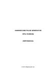
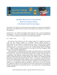
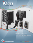
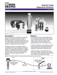
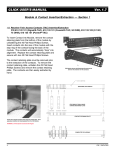
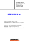
SUBNANOSECOND PULSE GENERATOR
PPG-2/1000
USER MANUAL
© 2015 Megaimpulse Ltd.
Copyright © 2015 MEGAIMPULSE Ltd. All Rights Reserved.
MEGAIMPULSE LTD. PROVIDES THIS MANUAL "AS IS" WITHOUT WARRANTY OF ANY KIND,
EITHER EXPRESS OR IMPLIED, INCLUDING BUT NOT LIMITED TO THE IMPLIED WARRANTIES OR
CONDITIONS OF MERCHANTABILITY OR FITNESS FOR A PARTICULAR PURPOSE. IN NO EVENT
SHALL MEGAIMPULSE LTD., ITS DIRECTORS, OFFICERS, EMPLOYEES OR AGENTS BE LIABLE FOR
ANY INDIRECT, SPECIAL, INCIDENTAL, OR CONSEQUENTIAL DAMAGES (INCLUDING DAMAGES
FOR LOSS OF PROFITS, LOSS OF BUSINESS, LOSS OF USE OR DATA, INTERRUPTION OF BUSINESS
AND THE LIKE), EVEN IF MEGAIMPULSE LTD. HAS BEEN ADVISED OF THE POSSIBILITY OF SUCH
DAMAGES ARISING FROM ANY DEFECT OR ERROR IN THIS MANUAL OR PRODUCT.
SPECIFICATIONS AND INFORMATION CONTAINED IN THIS MANUAL ARE FURNISHED FOR
INFORMATION ONLY, AND ARE SUBJECT TO CHANGE AT ANY TIME WITHOUT NOTICE, AND
SHOULD NOT BE CONSTRUED AS A COMMITMENT BY MEGAIMPULSE LTD. MEGAIMPULSE LTD.
ASSUMES NO RESPONSIBILITY OR LIABILITY FOR ANY ERRORS OR INACCURACIES THAT MAY
APPEAR IN THIS MANUAL, INCLUDING THE PRODUCTS AND SOFTWARE DESCRIBED IN IT.
Products and corporate names appearing in this manual may or may not be registered trademarks or copyrights of
their respective companies, and are used only for identification or explanation and to the owners' benefit, without
intent to infringe.
Megaimpulse Ltd. contact information
Address:
www:
e-mail:
fax:
26 Polytechnicheskaya str., St. Petersburg, 194021 Russia
http://www.megaimpulse.com
[email protected]
+7-812-297-3145
CONTENTS
Safety manual ................................................................................................... 2
Package content ................................................................................................ 3
General view of PPG-2/1000 subnanosecond pulse generator ......................... 3
Description of the generator ............................................................................. 4
Technical specification ..................................................................................... 6
Front and rear panels view ................................................................................ 7
Putting the generator into operation .................................................................. 8
Triggering of the generator ............................................................................... 10
Warranty ........................................................................................................... 11
PPG-2/1000 subnanosecond pulse generator user manual
1
SAFETY MANUAL
Electrical safety
PPG-2/1000 generator is high voltage equipment. Please be very careful
and operate by qualified personnel only.
There is a risk of electric shock, strong electromagnetic interference,
damage of generator or other electronic equipment in case of improper use.
It is strongly prohibited to switch on the generator without output coaxial
cable. We recommend using of 50 centimeters length or more coaxial cable
between the generator and the load (antenna or first attenuator) to prevent
permanent damage of the generator. There is a risk of electrical arcing on
the open coaxial connector and destruction of output circuit of the
generator.
When adding or removing generator to or from the system, ensure that the
power supply is unplugged (in OFF state). Please apply power supply
voltages only after connecting output and input coaxial cables.
PPG-2/1000 generator is high power equipment. Please allow free air flow
around the generator for good cooling. Please do not place the generator in
fan down position on the table surface, because it prevents normal air flow.
Operation safety
Please read this manual before installing and using of the generator.
Before using the product, make sure that all cables are applicable and not
damaged. High voltage connectors should be clean and dry, free from dust,
dirt and any obstacles.
To avoid short circuits keep metal parts like clips, screws and staples away
from the generator.
The generator is designed to work in normal laboratory conditions. Avoid
dust, humidity and temperature extremes. Do not place the generator in any
place where it may become wet.
Place the generator on a stable surface.
If you encounter any technical problem with the generator, please contact
with Megaimpulse Ltd. Do not try to repair the generator by yourself.
MEGAIMPULSE LTD.
2
PACKAGE CONTENT
Please check the package for the following items:
PPG-2/1000 subnanosecond pulse generator (hereinafter "generator")
DC power supply cable
User manual
Optional items:
Dual voltage AC/DC switching power supply AC 90V..264V,
47Hz..63Hz / DC +90V..+105V(adjustable), 2.3A; +18V, 2.8A
Semirigid coaxial cable assembly N connector / SM141 cable /
N connector for the output signal feeding
Flexible coaxial cable assembly SMA connector / RG316 cable / SMA
connector for the input triggering signal feeding
Flexible coaxial cable assembly SMA connector / RG316 cable / BNC
connector for the input triggering signal feeding
Fig.1. PPG-2/1000 subnanosecond pulse generator. General view from
input connectors and control LED side.
PPG-2/1000 subnanosecond pulse generator user manual
3
DESCRIPTION OF THE GENERATOR
PPG-2/1000 generates subnanosecond unipolar bell like 2 kV pulses with
up to 1 MHz repetition rate. Output pulse waveform is shown in Fig.2. The
generator is designed to operate on 50 Ohm matched load only, i.e. 50 Ohm
resistive load or matched impedance antenna connected by 50 Ohm impedance
coaxial cable. Operation on unmatched load inevitably results in part of energy
reflection from the load back to generator, overheating of the generator and
possible damage. It is strongly prohibited to switch on the generator without the
load (with open connector). We recommend using of 50 centimeters length or
more coaxial cable between the generator and the load (antenna or first attenuator)
to prevent damage of the generator in case of load breakdown.
Fig.2.
PPG-2/1000 output pulse waveform.
PPG-2/1000 should be triggered by external triggering pulse. There is no
internal triggering mode. Nominal triggering pulse amplitude is +5V at 50 Ohm,
pulse duration is 30 ns, rise/fall times is 1 ns. Longer than 3 ns rise time results in
increasing of the output pulse jitter.
The generator requires external dual voltage DC power supply, including
DC +18V (low voltage) and DC +90V..+105V (high voltage). Output pulse
amplitude is proportional to the level of high voltage DC supply. It is possible to
adjust the output pulse amplitude smoothly by adjusting high voltage DC supply.
Do not exceed DC +105V level for high voltage supply. There is a risk of damage
of the generator.
The generator comes with four wires DC power supply cable. The ground
wires are marked by black color. Low voltage supply wire is marked by “18”
label, high voltage supply wire is marked by “105” label.
MEGAIMPULSE LTD.
4
The contact pins on power supply connector are the following:
Pin 1 – DC +90V..+105V supply voltage
Pin 2 – ground return (DC +90V..+105V)
Pin 3 – DC +18V supply voltage
Pin 4 – ground return (DC +18V)
PPG-2/1000 is high power unit. The mean output power at 1 MHz
repetition rate is 100 W. Total power consumption is up to 200 W. Therefore, total
energy efficiency of the generator is about 50% and up to 100 W should be
dissipated. Two fans and heat sink with thermal tubes are used for this purpose.
The rotation speed of the fans is determined by the current dissipated power and
the temperature of the generator. When the temperature becomes higher the
rotation speed increases. It helps to keep the stable temperature of the generator
and reduces temperature drift of the output pulse.
There are internal over temperature and over frequency protection. If
temperature of the generator is too high then generator stops the operation and red
LED “OVERHEAT” lights on. In this case please allow idle operation during few
minutes. When the temperature decreases the generator returns to normal operation
regime automatically. If the triggering pulses frequency is more than 1 MHz then
the generator blocks triggering and red LED “OVERLOAD” lights on. Please
reduce the triggering pulses frequency below or equal to 1 MHz.
PPG-2/1000 subnanosecond pulse generator user manual
5
TECHNICAL SPECIFICATION OF PPG-2/1000
SUBNANOSECOND PULSE GENERATOR
Output pulse amplitude
2 kV
Pulse polarity and waveform
Positive unipolar bell like pulse
Output cable and load impedance
50 Ohm
Pulse rise time (20% - 80% levels)
600 ps
Pulse width (FWHM)
1.5 ns
Max repetition rate
1 MHz
Jitter (RMS)
40 ps
Jitter (peak-to-peak)
200 ps
Internal delay (from leading edge of
triggering pulse to output pulse)
< 100 ns
Temperature drift of internal delay
< 4 ns
Triggering
external
Input triggering pulse connector
SMA
Triggering pulse requirements
+5V amplitude at 50 Ohm, 30 ns width,
< 3ns rise time
Power supply
Dual DC: +90V..+105V, 2A;
+18V, 2A
Size
250 х 110 х 72 mm3 (without mounting
flanges)
Weight
1.5 kg
MEGAIMPULSE LTD.
6
INPUT CONNECTORS AND CONTROL LED SIDE VIEW
Control LED from left to right:
+18V DC (green) – low voltage power supply “+18V DC is applied”
+100V DC (green) – high voltage power supply “+90V..+105V DC is applied”
SYNC IN (orange) – triggering of the generator
OVERHEAT (red) – operation is stopped due to overheating of the generator
OVERLOAD (red) – triggering is blocked because frequency of triggering
pulses is above 1 MHz
Connectors:
SYNC IN
POWER SUPLLY
– SMA type input connector for external triggering signal
– connector for external DC power supplies
OUTPUT CONNECTOR SIDE VIEW
Connectors:
OUTPUT
– N type output connector
PPG-2/1000 subnanosecond pulse generator user manual
7
PUTTING THE GENERATOR INTO OPERATION
Please follow strictly the described steps. It helps to prevent damage of the
generator and other equipment.
Step 1.
Unpack the generator and check the presence into the package of the following
items:
- PPG-2/1000 pulse generator
- power supply cable
optional items:
- Dual voltage AC/DC switching power supply DC
+90V..+105V (adjustable), 2.3A; +18V, 2.8A
- Semirigid coaxial cable assembly N connector / SM141 cable /
N connector for the output signal feeding
- Flexible coaxial cable assembly SMA connector / RG316 cable / SMA
connector for the input triggering signal feeding
- Flexible coaxial cable assembly SMA connector / RG316 cable / BNC
connector for the input triggering signal feeding
Step 2.
⇒ If standard AC/DC switching power supply (optional) is included:
Do not connect initially DC power supply cable from AC/DC switching
power supply to the generator. Plug AC/DC switching power supply into
AC outlet. Check the low voltage power supply is DC +18V, high voltage
power supply is DC +90V..+105V. The exact recommended level of high
voltage power supply is written in the generator TESTING PROTOCOL
and on the sticker attached to the side panel of AC/DC switching power
supply.
Adjust the voltage levels by potentiometers if required. Unplug AC/DC
switching power supply from AC outlet
⇒ If standard AC/DC switching power supply is not included:
Please set external power supplies DC +90V..+105V, 2A and DC +18V,
2A. The exact recommended level of high voltage power supply is
written in the generator TESTING PROTOCOL. Switch off power
supply.
Step 3.
Connect the output coaxial cable and load to the generator.
Connect triggering pulse generator.
MEGAIMPULSE LTD.
8
Connect four wire DC power supply cable. The ground wires are marked by black
color. Low voltage supply wire is marked by “18” label, high voltage supply wire
is marked by “105” label.
Step 4.
Switch on (plug) AC/DC switching power supply. Both green LED “+18V DC”
and “+100V DC” on the generator should light on.
Set external triggering pulses frequency to 1 kHz. Apply triggering pulses, orange
LED “SYNC IN” should light on.
2 kV output pulses should be generated. Check them.
Set external triggering pulses frequency to required range below or equal to
1 MHz.
Please pay attention that standard GHz range attenuators are not suitable for
direct registration of output pulses because of extremely high peak power.
Even 100W and more power attenuators will be broken inevitably. We
recommend using of high voltage directional coupler or GHz range well
adjusted resistive splitter.
The generator is designed for long time operation at max repetition rate 1 MHz.
But it can be overheated in case of limited air flow around the generator or high
room temperature. Red LED “OVERHEAT” lights on in this case and generator
stops the operation. Please allow idle operation during several minutes for the
cooling. LED “OVERHEAT” lights off and generator returns to normal operation
automatically when the temperature decreases.
The maximum repetition rate is 1 MHz. If triggering pulses frequency is above this
level then red LED “OVERLOAD” lights on and generator stops the operation.
Please reduce the triggering pulses frequency.
PPG-2/1000 subnanosecond pulse generator user manual
9
TRIGGERING OF THE GENERATOR
The recommended triggering pulse waveform is shown in Fig. 3. Nominal
triggering pulse amplitude is +5V at 50 Ohm, pulse duration is 30 ns, rise/fall
times are 1 ns. Longer than 3 ns rise time may results in increasing of the output
pulse jitter.
Fig. 3. Recommended triggering pulse waveform.
MEGAIMPULSE LTD.
10
WARRANTY
Please see your sales agreement to determine the warranty period and warranty
condition. The generator has warranty seals.
Removing of the warranty seals terminates the warranty.
PPG-2/1000 subnanosecond pulse generator user manual
11