1
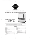
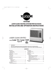
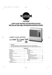
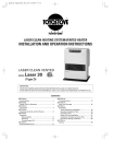
LASER CLEAN HEATING SYSTEM/VENTED HEATER
INSTALLATION AND OPERATION INSTRUCTIONS
LASER CLEAN VENTED
MODEL
Laser 56
(Type I)
IMPORTANT
READ AND UNDERSTAND INSTRUCTIONS BEFORE INSTALLING OR USING HEATER.
RETAIN INSTRUCTIONS FOR FUTURE REFERENCE. CHECK LOCAL CODES FOR PERMITTED USE.
CONTENTS
SECTION A:
Specifications ················································ 2
Safety Features ·············································· 3
SECTION B:
Safety Tips for Operation ································ 4
SECTION C:
Fuel Guide ···················································· 5
SECTION D:
Operating Controls and Part Names ················· 6
SECTION E:
Operation
Before Ignition ··········································· 9
Operation ·················································· 9
Turning Heater Off ···································· 12
SECTION F:
Routine Maintenance ···································· 12
SECTION G:
Troubleshooting············································
SECTION H:
Long Term Storage········································
SECTION I:
Installation
Tools Needed for Installation ······················
Standard Installation Parts ·························
Accessary Parts ········································
Safety Tips for Installation ··························
Installation of Heater and Flue Pipe ·············
Permanent Wiring Installation ····················
SECTION J:
Fueling ························································
14
16
17
17
19
22
23
29
30
SECTION A:
SPECIFICATIONS
Model:
Laser 56
Heater Efficiency:
93% (1)
Heat Rating:
High - 22,000 BTU/h (6,453 Watts)
Med - 15,000 BTU/h (4,400 Watts)
Low - 8,000 BTU/h (2,347 Watts)
Fuel Consumption:
High - 0.165 gal/h (0.625 L/h)
Med - 0.113 gal/h (0.428 L/h)
Low - 0.060 gal/h (0.227 L/h)
Fuel System:
External tank (2)
Fuel Type:
ASTM No.1-K Kerosene Only
Dimensions (W ×H ×D):
(Includes drip tray)
24-3/8“ × 26-3/4“ × 16“
(62.0 × 68.0 × 40.5 cm)
Weight:
60 lbs. (27 kg) Empty
Vent Pipe Hole:
2-3/4“ ~ 3“ diameter
(7.0 - 7.5 cm)
Maximum Length of Vent Pipe System:
10 ft. (3 m), 3 bends or less
Electrical Rating:
120 Volts AC, 60 Hz
Preheat - 275W
Burning - 60W
Typical Room Size (3):
920 square feet (0°F)
1100 square feet (20°F)
(1) Heat and vaporized water are produced by the combustion process of this kerosene heater. This rating
does not take into account heat loss due to condensation of water vapor.
(2) External tank to be purchased from local suppliers.
(3) 0° F Heat Load = 24 BTU/ft2/hr
20° F Heat Load = 20 BTU/ft2/hr
Room size for which this heater is suitable will vary depending on outside temperature, house
insulation, window size, and other factors.
2
SAFETY FEATURES
Your Laser 56 is equipped with the following safety features. Please familiarize yourself with these features.
When your heater is extinguished due to a safety mechanism, be sure to identify and correct the problem.
1.
Flame Sensor
Heater will automatically stop all operations if ignition fails or if flame fails during combustion, in order
to prevent fuel overflow. Error code will be displayed on the digital indicator.
2.
Fuel Strainer
Special strainer catches any dirt or impurities present in the fuel before it is sent to the burner.
3.
Overheat Protector
Automatically stops all operations if heater cabinet reaches abnormally high temperature due to motor
malfunction or abnormal combustion, in order to prevent fire.
4.
Power Failure Recovery System
If power fails during heater operation, heater will turn off. When power resumes, heater will
automatically reignite to maintain the selected room temperature.
5.
Fully Vented System
Flue pipe system provides outside air for combustion and vents all combustion products to the
outdoors.
6.
Fusible Link Valve
If a household fire should occur, bringing the fuel line or heater to extremely high temperatures, the
fusible link valve will stop the fuel supply to the burner. This will prevent the fuel supply from the
external tank continuing to flow into the house.
3
SECTION B:
SAFETY TIPS FOR OPERATION
CAUTION: Heater and vent pipe system must be properly installed before operation.
Please follow instructions under “Installation”, Section I.
1.
Never use any fuel other than clear or red colored kerosene (ASTM No. 1-K
Kerosene). NEVER USE GASOLINE. Use of gasoline can lead to
uncontrollable flames, resulting in destructive fire.
RIGHT
WRONG
KEROSENE
GAS
Due to high surface temperatures, keep heater away from children, furniture
and clothing while in operation (See Page 24).
3.
To prevent abnormal operation and prolong heater life, be sure to perform
routine maintenance (See Pages 12-13).
4.
Never store or transport kerosene in other than a metal or plastic container
that is (1) acceptable for kerosene, (2) non-red in color, and (3) clearly
marked, “KEROSENE”. Never store kerosene in the living space.
5.
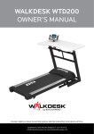
Operating Temperature Range
Use heater within the range of temperatures
indicated in the right figure.
Point A: If outside temperature -20°F
than room temperature has to be 0°F or above
Point B: If outside temperature -45°F
than room temperature has to be 60°F or above
Outside Temperature (˚F)
2.
-20
A
Operating Range
-25
-30
-35
-40
-45
B
0
20
40
Room Temperature (˚F)
4
60
SECTION C:
FUEL GUIDE
The Toyostove Laser 56 is designed for use with clear or red colored No.1-K kerosene only. Use of low-quality
kerosene will cause burner performance to drop, leading to abnormal combustion and reduced heater life.
Purchase only 1-K kerosene in non-red cans reserved exclusively for kerosene and marked accordingly with
the word “KEROSENE”. Always store your kerosene in a separate area from where you store gasoline for
your power equipment to avoid accidental use of gasoline in your heater.
What to Buy . . .
Crystal clear or red colored, high-quality KEROSENE, ASTM
ALWAYS :
No.1-K.
ALWAYS :
Kerosene free of contaminants, water or cloudiness.
NEVER :
Gasoline, alcohol, white gas, camp stove fuel or additives.
NEVER :
Yellow or sour-smelling fuel.
How to Use It . . . (when optional removable fuel tank is used)
Fill heater away from living quarters when heater is cool; use
ALWAYS :
siphon.
ALWAYS :
Watch fuel gauge to avoid overfilling heater.
GAS
How to Store It . . .
Store in a clean container, non-red in color, clearly marked
ALWAYS :
KEROSENE.
ALWAYS :
Store away from direct sunlight, heat sources or extreme
temperature changes.
NEVER :
In a glass container, or one that has been used for other fuels.
NEVER :
For longer than six months. Begin each heating season with
fresh kerosene; discard at the end of season.
NEVER :
In the living space.
Why It is Important . . .
Pure, clean kerosene is essential for safe and efficient heater operation. Poor
quality or contaminated kerosene can cause:
¡Excess tar deposits on burner and flue pipe
¡Incomplete combustion
¡Reduced heater life
Use of a highly volatile flammable fuel such as gasoline can produce
uncontrollable flames, creating a severe fire hazard.
5
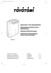
SECTION D:
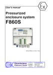
OPERATING CONTROLS AND PART NAMES
Before using heater, familiarize yourself with the following operating controls and part names.
6
1.
ON/OFF switch:
Main switch which turns heater on and off. When switched on,
heater begins operation and combustion starts after preheat
period.
2.
Auto switch:
The switch turns automatic operation modes on and off which
have been programmed into timer.
3.
Temperature selectors:
“NORMAL” and “SET-BACK” temperature selectors allow user to
select desired temperature during manual or automatic operation.
4.
Timer & clock set:
Timer and clock set modes can be set by pressing hour or minute
buttons.
5.
Timer selector:
Clock, clock set, “SET-BACK” mode, start time set and end time
set can be selected by this switch.
6.
Digital indicator:
Displays clock, set temperature, room temperature and error code.
7.
Burning mode lamp:
Indicates whether heater is operating at high, medium or low
combustion.
8.
ON/OFF lamp:
Lights when heater is in operation and flashes when heater is in
prepurge or postpurge.
9.
Auto lamp:
Lights when automatic operation is in use.
10. Normal temperature lamp:
Lights when heater runs with manual or “NORMAL” mode of
automatic operation.
11. Set-back temperature lamp:
Lights when heater runs with “SET-BACK” mode of automatic
operation.
12. Circulating fan:
Three-speed motor supplies high-capacity warm air flow during
high combustion for heating room up quickly, and low or
medium-capacity warm air flow during low or medium
combustion for maintaining comfortable room temperature.
13. Room temperature sensor:
Constantly senses room temperature and supplies information to
heater so that desired room temperature can be maintained.
14. Power supply cord:
For use in 120V, AC electrical outlets only.
15. Plumb bob:
Allows user to check if heater is positioned evenly.
INDICATOR LAMPS
ON/OFF lamp
Flashing
Lit
- Pre-heating, pre-purging and post-purging mode
- Heater in operation
AUTO lamp
Flashing
Lit
- Power loss of more than 10 seconds
- Heater in operation at auto mode
LOW lamp
Lit
- Heater in operation at low combustion
MED lamp
Flashing
Lit
- Pre-purging mode (without flame)
- Heater in operation at medium combustion
HIGH lamp
Lit
- Heater in operation at high combustion
NORMAL lamp
Lit
- Heater in operation at normal mode
SET-BACK lamp
Lit
- Heater in operation at set-back mode
7
59
60
63
7
6
8
57
56
71
68
2
45
11
63
63
63
52
12
63
58
67
64
63
43
42
63
53
1
49 48
44
63
13
72
41
2
74
63
61
46
62
63
51
36
47
70
76
25
26
33
63
36
35
40
63
24
66
15
14
22
65
31
50
38
63
65
75
29
63
78
80
77
28
17 16
39
63
23
32
63
63
73
8
67
27
69
34
10
37
63
74
30
3
63
34
63
9
54
79
5
20
19
18
21
63
4
81
55
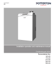
RE. #
PART #
DESCRIPTION
RE. #
PART #
DESCRIPTION
RE. #
PART #
DESCRIPTION
1
2
3
4
5
6
7
8
9
10
11
12
13
14
15
16
17
18
19
20
21
22
23
24
25
26
27
28
20478346
20475804
20450007
20474970
20475929
20475960
20475965
20475566
20478063
20475570
20478064
20475072
20478044
20478542
20478343
20478026
20478383
20475518
17185580
20474921
20474920
20475011
20475094
20475093
20475831
20475881
20474992
20478737
Front panel assembly
Carrying handle
Plumb bob
Adjustable leg
Drip tray
Top plate with tank lid
Tank lid with pin
Tank lid pin
Right side panel with access door
Level valve access door with pin
Left side panel
Fan cover
Heat exchanger
Burner assembly
Burner ring
Fuel nozzle
Fuel nozzle gasket
Igniter
Igniter gasket
Igniter guide gasket
Igniter cover
Primary flame rod
Burner gasket
Heat chamber gasket
Mica window
Peep window gasket
Joint packing
Blower motor assembly
29
30
31
32
33
34
35
36
37
38
39
40
41
42
43
44
45
46
47
48
49
50
51
52
53
54
55
56
20478747
20475971
20475983
20475978
20478082
20475977
20478534
20478319
20478041
20478550
20475551
20475552
20478512
20478378
20478379
20478317
20478306
20478376
20478301
20477414
20478314
10005597
20475952
20478569
20478373
20479891
20474925
20475922
Blower motor assembly with case
Blower motor exhaust fan
Blower motor intake fan
Rubber mat
O-ring (ø110)
O-ring (ø49)
Fuel sump
Fuel pump
Fuel pipe assembly
Inlet strainer
Drain screw with O-ring
Strainer gasket
Main circuit board
Fuse A
Fuse B
Transformer
High limit switch
Indicator lamp circuit
Knob for temp selector
PCB Support
PCB Support (S)
Fusible link valve
Leveler fuel pipe
Circulation fan motor
Thermistor
Flue pipe
Oil catch
Removable fuel tank with hose
57
58
59
60
61
62
63
64
65
66
67
68
69
70
71
72
73
74
75
76
77
78
79
80
81
82
83
20475722
20475925
20475924
20475923
20474059
20478156
20474050
20474039
20474057
20475553
20474055
20450120
20478091
20478090
20475554
20474049
20474272
20474051
20475874
20478509
20474983
20478326
20478366
20478683
20475535
20478794
20478798
Removable fuel tank without hose
Fuel supply hose
Fuel tank cap
Fuel gauge
Holder A
Screw 1S
Screw C (=20478091)
Insulator A
Flange nut
Screw 1P
Screw O
Screw for igniter unit
Screw 1U (=20474050)
Screw 1T
Screw Q
Screw R
Screw M
Screw D
Washer for blower motor
Heat chamber assembly
Outlet adapter
Burner coating
Air damper (ø25)
Draft tube
Power supply cord
Instruction Manual
Carton
SECTION E:
OPERATION
BEFORE IGNITION
1.
Open the Valve(s)
Open the valve(s) of the external fuel tank.
2.
Start the Fuel flow
If using heater for the first time, or after heater has been out of fuel, press
the red reset button once for a period of one second in order to send fuel
to the fuel sump.
Note: Make sure there is no fuel leakage from the fuel line or joints.
Also make sure fuel tank is not too high. See installation instructions.
3.
Plug in the Heater
Plug heater into a 120V AC electrical outlet.
Note: Do not connect to an outlet shared with other appliances.
Programmable Set Back
SET
ROOM
6. Digital Indicator
TEMP
AM
PM
4.
Set Clock
Important: Clock on the heater always
must be set to current time.
A. Position timer selector to “CLOCK SET”.
B. Press “HOUR” and “MINUTE” button
of TIMER/CLOCK SET to correct time.
Important: Check for the AM or PM
indicators, to insure the
correct time.
Note:
Note:
7. Burning mode lamp
E
OD
GM
IN
RN
W
LO
BU
H
HIG
ED
M
9. Auto lamp
8. ON/OFF lamp
1. ON/OFF switch
ER
RN
BU
TO
AU
2. Auto switch
ON
ON
F
OF
10. Normal temperature lamp
11. Set-back temperature lamp
P
M
TE
CT
LE
SE
AL
RM
NO
K
AC
T·B
SE
4. Timer & clock set
“HOUR” or “MINUTE” button will
change the time every one (1)
unit.
Holding
the
button
continuously will cause the time
to change rapidly.
CK
LO
E/C
TIM
F
OF
°F
50 °C
10
70
°F
50 °C
10
70
21
90
32
3. Temperature selector
21
90
32
T
SE
HOUR
MINUTE
5. Timer selector
CLOCK SET
CLOCK/TEMP
(NORMAL POSITION)
START SET-BACK
END SET-BACK
In the event of a power failure over ten (10) seconds, all clock and timer settings are cancelled.
Digital indicator will flash “PM 12:00” when heater is off, or “AUTO” lamp will flash when
heater is on and in automatic operation, after is power is restored. However, no indications
when heater is in manual operation. At this point, you need to reset all time and set-back
functions.
C. Position timer selector to “CLOCK/TEMP (NORMAL POSITION)” after clock setting is completed.
Current time will be shown on digital indicator.
OPERATION
Operation of Laser Heater can be controlled manually by the user - “MANUAL” operation (NORMAL mode
only) or run automatically by the programming - ”AUTOMATIC” operation (NORMAL mode and SET-BACK
mode).
MANUAL OPERATION
“MANUAL” operation means that the set-back will not be in use but in ”NORMAL” mode.
Operation of the heater is under the direct control of the user (“AUTO” switch is off). Heat output will,
however, be automatically adjusted in accordance with the room temperature registered by the
temperature sensor.
9
1.
Select Manual Operation
Press the “AUTO” switch to “OFF” position.
2.
Turn Heater ON
A. Push in ON/OFF switch to “ON” position. The current room temperature
and the set temperature will be shown on the digital indicator. ON/OFF
lamp will start to flash and then blower motor and ignition will start.
Note:
Heater will not start when room temperature is higher than the
desired temperature setting.
B. Burning mode lamp “MED” will start to flash after approx. 3 - 9 minutes
and ignition will take place. (*) After ignition, burning mode lamp “MED”
will change from flashing to continuous. And, after 10 seconds, burning
mode lamp will turn to “LOW” and heater will start “LOW” burning mode.
Circulation fan will turn on after approx. 3 minutes.
Note: (*) Pre -heating depends on the room temperature.
Room temperature:
below 34°F - 9 minutes
34°F - 61°F - 6 minutes
over 61°F - 3 minutes
C. Heater will operate at “LOW” or “MED” burning mode for approx. 6
minutes after ignition, regardless of temperature control setting. Heater
will not go into “HIGH” burning mode while the prepurging is in effect.
After this period, output can be adjusted as desired by using the
”NORMAL” temperature selector as directed in following instructions.
3.
Adjusting Room Temperature
A. Slide “NORMAL” temperature selector to set the room temperature
desired. The temperature control should be set at the position you find
most comfortable.
Note:
Desired temperature setting will be displayed on the digital
indicator when you set the room temperature.
Note:
The scale on temperature selector is just for your reference. The
figures on the digital indicator and on the scale may not match
exactly; This is normal.
B. Burning mode will be regulated automatically in accordance with the room temperature registered by
the room temperature sensor. Heater will be operated at “HIGH” burning mode until room temperature reaches the selected temperature level.
C. When room temperature reaches the selected setting, heater will automatically shift to “MED” or
“LOW” burning mode to maintain the desired temperature.
When room temperature exceeds the selected setting by approx. 4°F, the heater will automatically
shut off. As room temperature drops, the heater will automatically re-start to maintain the desired
temperature.
10
Approx. +4˚F
Approx. +1˚F
SET
TEMP.
High
Medium
Low
Off
Re-Ignition
AUTOMATIC OPERATION
“AUTOMATIC” operation is established by programming the time/temperature settings for specific
time, “SET-BACK” mode operation will be programmed in a 24-hour period. It is designed for energy
efficiency by using a lower temperature setting, generally at night.
Ex.
75˚F
“NORMAL”
mode
“NORMAL”
mode
60˚F
“SET-BACK”
mode
PM10:00
AM6:00
Start Set-Back
1.
60˚F
PM10:00
AM6:00
End Set-Back
Set Start Time of “SET-BACK” Mode.
A. Slide the timer selector to “START SET-BACK”.
B. Press “HOUR“ and “MINUTE” button of TIMER/CLOCK SET to set desired start time.
Note: When setting “SET-BACK” time, the “MINUTE” button will advance time by ten (10) units.
(Ex. 10:00, 10:10, 10:20, etc.)
C. Start time of “SET-BACK” mode will be shown on digital indicator. (Ex. PM 10:00)
2.
Set End Time of “SET-BACK” Mode.
With the timer selector slide switch in the “END SET-BACK” position, program the end time as
described above. (Ex. AM 6:00)
Important: Always return timer selector to “CLOCK/TEMP (NORMAL POSITION)” after settings.
3.
Set Room Temperature.
Slide “NORMAL” temperature selector and “SET-BACK” temperature selector at the position you
desire. (Ex. “NORMAL” - 75˚F, “SET-BACK” - 60˚F)
Note: The temperature setting currently being used is displayed on the digital indicator. To view and
set the Set-Back temperature setting, press the “MINUTE” button for more than three (3)
seconds. The display will go back to the Normal temperature setting after ten (10) seconds.
4.
5.
Push in AUTO switch to “ON” position.
Turn Power ON.
Press ON/OFF switch to “ON” position. ON/OFF lamp will start to flash and AUTO switch lamp will light.
And then blower motor and ignition will start.
Note: SET-BACK OPERATION IRREGULAITIES: If a heater is switched “OFF”; if the “AUTOMATIC”
operation is switched off; or there is a power interruption while the unit is operating in the
“SET-BACK” mode, the “SET-BACK” mode may be temporarily disabled until the next Start
Set-Back time.
11
TURNING HEATER OFF
Press ON/OFF switch to “OFF” position. (AUTO lamp and temperature lamp will
go out. Burning mode lamp will flash until flame disappears.) Circulation fan and
blower motors continue to run for approx. three (3) minutes to cool down the
heater. Make sure ON/OFF lamp goes out when the fan stops.
Note:
If ON/OFF switch is pressed to “ON” position during the cool down period, the heater will automatically re-start at the end of cool down period.
Note:
Disconnect the heater plug from the electrical outlet after the power lamp
has turned off if the heater will go unused for a prolonged period. The
plug should also be disconnected during electrical storms.
Note:
Heater may also be shut down by lowering the setting on the temp. selector thermostat(s) because heater goes into “OFF” cycle.
MANUAL COMBUSTION
Important:
This feature is for testing purpose only!
This heater also can be kept burning at desired combustion mode (High, Medium or Low) manually, regardless of room
temperature.
1. Press the “HOUR“ button and “MINUTE“ button at the same time for more than three (3) seconds when
ON/OFF switch is “ON“.
2. P1, P2 or P3 will be displayed on the Digital Indicator;
P1 = Low mode
P2 = Medium mode
P3 = High mode
Then select desired combustion mode by pressing “MINUTE“ or “HOUR“ button. “MINUTE“ button changes combustion mode to higher, “HOUR“ button changes combustion mode to lower.
3. To clear, press the “HOUR“ button and “MINUTE“ button at the same time for more than three (3) seconds until
normal temperature display returns.
SECTION F:
ROUTINE MAINTENANCE
CAUTION: Be sure to unplug heater before performing any checks or cleaning.
CAUTION: Allow heater to cool completely before cleaning or maintenance.
FOR OPTIMUM HEATER PERFORMANCE, THE PARTS SHOWN BELOW SHOULD BE CLEANED REGULARLY:
12
1.
Clean Louvers (ONCE A WEEK)
Dust and stains should be wiped off louvers with a damp cloth.
2.
Clean Circulation Fan Cover (ONCE A WEEK)
Remove any dust or pet hair from the fan cover on the back of the heater.
3.
Check for Fuel Leaks (REGULARLY)
Make it a habit to check for any sign of kerosene leakage along the fuel line
and at all joints. Kerosene leaks may lead to risk of fire.
4.
Check Flue Pipe Area (ONCE A WEEK)
Check the flue pipe joint to make sure connection is firm. Use a vacuum
cleaner to remove any dust or pet hair.
Check
5.
Clean Fuel Strainer (ONCE A MONTH)
The strainer of the fuel sump should be cleaned once a month and before
storing heater at the end of each season.
(a) Close the valve(s) of the separate fuel tank.
(b) To catch the fuel which will drain out, set the oil catch below the strainer
cover, with a small container under it.
(c)
Loosen the two screws from the strainer cover and remove.
Fuel Sump
(d) Remove the strainer and wash with kerosene.
(e) Return the strainer to its original position. Replace strainer cover and
Strainer
Cover
screw to secure.
(f)
Wipe away any spilled kerosene.
(g) Open the valve(s) of separate kerosene tank. Check for fuel leakage.
(h)
Oil Catch
Turn the knob of the fusible link valve counterclockwise to open. Check
for kerosene leakage.
Note:
At the end of each season unscrew the drain screw to remove all the
remaining kerosene from the fuel sump.
Be sure to follow the A, B and C procedure listed above.
Drain
Screw
Fuel strainer
13
SECTION G:
TROUBLESHOOTING
NOTE BEFORE REQUESTING FOR REPAIR AND SERVICES
The following symptoms are normal during operation of the heater.
When heater is
in operation.
When heater is started
or extinguished.
CONDITION
REASON
White smoke or smell at initial use after
purchase.
Machine oil or dust burns of the surfaces of
the burner or heat exchanger.
Flames flashing for a few minutes after
ignition.
The burner is cold and igniter is kept running
for a while after ignition.
Occasionally makes “cracking” noise when
heater is ignited or extinguished.
Expansion and shrinkage of metal parts when
they are heated or cooled.
Warm air will not blow as soon as ignited.
To prevent uncomfortable cool air from
coming out at the beginning, circulation fan
start up is delayed.
Audible chugging sound from fuel pump
when started first time or after running out
of fuel.
Air is in the pump. However, noise should
stop within 1 minute.*
“Ticking” noise.
Noise of fuel pump in operation.
Normal.
Part of the heat chamber or the heat
exchanger is heated to a cherry red color.
Normal.
Occasional yellow flickering in blue flame.
Normal.
*If sound from fuel pump does not decrease and heater shuts off, check:
1.
Push red reset button on fuel sump. DO NOT hold down.
2.
Insure that all valves are open and filter is clear.
3.
Insure external fuel tank has fuel and filters are clean.
AUTOMATIC CLEANING SYSTEM
Heater will automatically clean igniter for ten (10) minutes every day at 2:00 a.m. and display “CL:10” on
Digital Indicator if heater is running at that time.
MANUAL CLEANING SYSTEM
Heater will clean igniter for ten (10) minutes manually.
1.
Press the “HOUR” button and “MINUTE” button at the same time for more than three (3) seconds when
ON/OFF switch is “OFF”.
2.
Display will appear “CL:10” on Digital Indicator. Cleaning will begin and end without any additional
input.
Note:
14
Cleaning igniter is important to prolong igniter life. It is recommended that the igniter be cleaned
once a week.
Should problems arise during operation or ignition, use this chart to determine the cause and the proper
steps to take. Be sure to unplug heater and allow to cool completely before taking corrective measures.
In the event that heater should extinguish itself, without any action or your part, you should look to the digital indicator for any of the following error codes.
DISPLAY/LAMP
EE2
EE2
EE2
PROBLEM
SOLUTION
Disconnected power plug
Circuit board malfunction
Plug into 120V AC outlet.
Consult your dealer.
NO IGNITION*
Out of fuel
Fuel tank valve closed
Air pocket in fuel line
Check fuel gauge on fuel tank; refuel.
Open valve by turning counterclockwise.
Push reset button on the fuel sump,
located right inside, once.
Clean flue pipe.
Clean fuel strainer (See page 13).
Consult your dealer.
EE2
EE2
EE2
Clogged flue pipe
Clogged fuel strainer
Igniter, circuit board, flame
sensor or fuel pump malfunction
Blower motor malfunction
EE8
EE6
CAUSE
POWER LAMP
FAILS TO TURN ON
EXTINGUISHED
AFTER IGNITION
Air pocket in fuel line
Consult your dealer.
EE6
EE6
Out of fuel
High limit switch activated
EE6
EE6
EE6
EE6
EE8
Fuel flow obstruction
Tank too high
Fuel sump valve malfunction
Flame sensor malfunction
Blower motor malfunction
Push reset button on the fuel sump,
located right inside, once.
Check fuel gauge on fuel tank; refuel.
Clean circulation fan cover, remove any
obstructions.
Consult your dealer.
Re-locate fuel tank.
Consult your dealer.
Consult your dealer
Consult your dealer.
POOR COMBUSTION/
NOISY COMBUSTION
Soot buildup in flue pipe
Burner ring not properly seated
Altitude too high (See page 23.)
Clean out any soot.
Consult your dealer.
Consult your dealer.
DOES NOT
EXTINGUISH
Possibly excess fuel in burner
Flame sensor malfunction
Consult your dealer.
Consult your dealer.
ODOR
Leaking flue pipe
Kerosene leakage
Tighten all flue pipe connections.
Tighten all fuel line joints. Wipe away any
kerosene drippage.
Consult your dealer.
EE10
Faulty packing or gasket in
combustion area
Hi
Room temp is over 95˚F.
Incorrect location of room temp
sensor
Correct the location of the room temp
sensor.
Lo
Room temp is lower than 14˚F.
Room temp sensor malfunction or
disconnected
Check room temp sensor.
Low/Med/ DOES NOT
High lamps EXTINGUISH
flashing at
the same
time
Possibly excess fuel in the burner or
flame sensor
malfunction (miss detection)
Consult your dealer.
WARNING: Do not re-use the unit until the cause of the “EE10” code has been determined.
If the corrective measures outlined above do not solve the problem, please consult your TOYOSTOVE dealer.
*Note: If the unit fails 3 times after checking all causes listed, DO NOT CONTINUE turning the power switch
on and off. (Consult your dealer.)
15
SECTION H:
LONG TERM STORAGE
At the close of each heating season, or when you do not plan to use your heater for an extended period, the
following procedures are recommended.
1.
As the end of the season approaches, calculate your kerosene purchases so that you can use up all the
kerosene you have on hand. When kerosene is stored for over six months, its quality may deteriorate.
The use of such kerosene will have an unfavorable effect on heater operation.
2.
If your heater needs any service or repair, now is the time to call your dealer and get it done before
storage. That way your heater will be ready for immediate use when the next heating season begins.
3.
If you plan to store your heater in place,
(a)
Disconnect power supply.
(b) Close the main tank valve.
(c)
Remove all kerosene from the fuel sump and clean the fuel strainer.
(See page 13.)
(d) Wipe off any stains or dust on heater with a damp cloth, then wipe once
again using a dry cloth.
(e)
16
Cover heater completely with a large plastic bag to protect from dust.
SECTION I:
INSTALLATION
TOOLS NEEDED FOR INSTALLATION
Tool
Phillips Head Screwdriver
Electric Drill
Hole Saw, 2-3/4 to 3“ diameter
Use
Installation of flue pipe, etc.
Drilling hole in wall for flue pipe
Making hole in wall for flue pipe
STANDARD INSTALLATION PARTS
The following standard installation parts are enclosed with heater. For alternate installation methods, you
may need to purchase additional accessories which are available from your TOYOSTOVE dealer. See
”Accessory Parts“, page 19.
Drip Tray (1) (PART #20475929)
Wall Brackets (2 sets) (PART #20474962)
Exhaust Extension pipe (s) (1) (PART #220479856)
Pipe Stopper (1) (PART #20474964)
Pipe Holder (2) (PART #20474963)
17
(3)
(3)
Flue Pipe (1)
Exhaust Air Cap (1)
Intake Air Cap (1)
(PART #20479891)
(PART #20479845)
(PART #20474949)
Bent Joint (1) (PART #20474984)
L-Shaped Hose (2) (PART #20474975)
Oil Catch (1) (PART #20474925)
Hose Band (2) (PART #20474977)
Inlet Hose (1) (PART #20474951)
18
Spacer (1) (PART #20478967)
ACCESSORY PARTS
The following accessory parts are available for use in non-standard installation of the Laser 56. After giving
careful consideration to your desired heater and flue pipe locations and fueling system, consult your
TOYOSTOVE dealer to purchase the necessary accessory parts.
Important: Use only genuine TOYOSTOVE parts for your heater. Use of unauthorized generic or other
brand parts can severely reduce performance and safety, and will invalidate factory warranty.
Accessory
Part No.
Application
Extension pipe kit (L)*
20479898
Extends pipe system by 61-3/4 to 78-3/4”
Extension pipe kit (M)*
20479897
Extends pipe system by 22-1/2 to 39-3/8”
Extension pipe kit (S)*
20479896
Extends pipe system by 12-5/8 to 19-5/8”
L-Shaped exhaust joint*
20479861
For 90 degree bend in exhaust pipe
Fuel lifter pump
Model OPT-81UL
22744990
Used to lift fuel to heater when fuel tank is located underground
or outdoors in a position lower than the heater.
With automatic recovery. (Not available in Canada)
Window Kit (L)
20475589
For installation of flue pipe in windows
from 31 to 50 inches wide. (Not available in Canada)
Window Kit (S)
20475588
For installation of flue pipe in windows
from 20 to 32 inches wide. (Not available in Canada)
External Fuel Supply
Installation Kit
10005098
For installation of external tank system
* Total length of extension pipe between heater and flue pipe must be no greater than 10 ft. No more than
three bends may be used in extension pipe.
L-Shaped exhaust joint
Pipe Support
Hardware
External Fuel Supply
Installation Kit
3-3/8
Fuel Lifter Pump Model OPT-81UL
3-1/2
PART #20474950
PART# 10005098
PART #20479861
Intake Pipe
6-1/2 ft.
FUEL
LIFTER PUMP
LOCATION
EXAMPLE
PART #22744990
PART #20474951
Exhaust Extension Pipe
35
39-3/8
10
Insulating cloth cover
Intake Pipe
Joint
40 inch
PART #20479872
3-1/2
FUEL
LIFTER PUMP
LOCATION
EXAMPLE
Adjustable Exhaust Pipe
Max. 39-3/8 ~ Min. 22-7/16
10
10
35
FUEL
TANK
PART #20474955
PART
#20474954
PART #20479853
Flue pipe extension
FUEL
TANK
PART #20479887 Flue pipe ext. (for wall up to "9~13")
PART #20479873 Flue pipe ext. (for wall up to "13~16")
PART #20479874 Flue pipe ext. (for wall up to "16~20")
PART
#20479875 Flue pipe ext. (for wall up to "20~24")
PART
#20479887
19
EXTENSION KIT
Max. 39-3/8 ~ Min. 22-7/16 inch
PART #20479898
7
INSTALLATION WITH EXTENSION PIPE KIT (L)
5
3-3/8
Extension Pipe Kit (L)
1
3-1/2
(# 20479861)
(# 20479853)
6
39-3/8 inch
(# 20474963)
(# 20474950)
Pipe Support Hardware
2
(# 20479872)
Pipe Holder (2 pcs.)
80 inch
Adjustable
Exhaust Pipe
3
Intake Hose
(# 20474951)
Pipe Holder Support (1 pc.)
Pipe
holder
40 inch
4
Nut (1 pc.)
Screw
(1 pc.)
(# 20474955)
No.
Name of Part
Q’ty
1
Adjustable Exhaust Pipe
Max. 39-3/8~ 22-7/16
1
2
Exhaust Extension Pipe
(long, 39-3/8 inch)
1
3
Intake Pipe (80 inch)
1
4
Insulating cloth cover
(40 inch)
2
5
Pipe Holder
2
6
Pipe Support Hardware
3
sets
7
L-Shaped Exhaust Joint
1
Wood Screw
(2 pcs.)
Pipe Support
Hardware
Figure 1
Insulation
cloth cover
Flue pipe
connection
Intake
Hose
Exhaust Extension
Pipe (long)
63-5/8~ 80-1/2
Heater
Exhaust
pipe
connection
When using the “Extension pipe (L)” extension kit, the distance
between the heater exhaust pipe connection and the flue pipe
connection must be at least 63-5/8 inch but no more than 80-1/2
inch. (See Figure 1 for reference.)
20
NOTE: Use “L”-shaped Exhaust Joint if necessary.
6
4
1
3-1/2
(# 20479861)
(# 20479853)
Extension Pipe Kit (S)
Max. 19-11/16 ~ Min. 12-5/8 inch
5
PART #20479896
6
4
3-3/8
Max. 39-3/8 ~ Min. 22-7/16 inch
PART #20479897
3-3/8
Extension Pipe Kit (M)
1
3-1/2
(# 20479861)
(# 20474963)
(# 20479858)
5
(# 20474950)
Pipe Support Hardware
(# 20474963)
(# 20474950)
Pipe Support Hardware
20 inch
40 inch
Pipe Holder (2 pcs.)
2
Pipe Holder (2 pcs.)
2
(# 20474951)
(# 20474951)
Pipe Holder Support (1 pc.)
Pipe Holder Support (1 pc.)
40 inch
40 inch
3
Nut (1 pc.)
Screw
(1 pc.)
(# 20474955)
No.
Name of Part
Q’ty
1
Adjustable Exhaust Pipe
Max. 39-3/8~ Min. 22-7/16
1
2
Intake Pipe (40 inch)
1
3
Insulating cloth cover
(40 inch)
1
Nut (1 pc.)
Screw
(1 pc.)
(# 20474955)
Figure 2
Flue pipe
connection
Intake
Hose
3
Wood Screw
(2 pcs.)
No.
Name of Part
Q’ty
1
Adjustable Exhaust Pipe
Max. 19-11/16~ Min. 12-5/8
1
2
Intake Pipe (20 inch)
1
3
Insulating cloth cover
(40 inch)
1
4
Pipe Holder
2
4
Pipe Holder
5
Pipe Support Hardware
2
sets
5
Pipe Support Hardware
1
sets
6
L-Shaped Exhaust Joint
1
6
L-Shaped Exhaust Joint
1
2
63-5/8~ 80-1/2
Figure 3
Intake
Hose
Flue pipe
connection
63-5/8~ 80-1/2
Heater
Exhaust
pipe
connection
When using the “Extension pipe (M)” extension kit, the distance
between the heater exhaust pipe connection and the flue pipe
connection must be at least 25-5/8 inch but no more than 42-1/2
inch. (See Figure 2 for reference.)
Wood Screw
(2 pcs.)
Heater
Exhaust
pipe
connection
When using the “Extension pipe (S)” extension kit, the distance
between the heater exhaust pipe connection and the flue pipe
connection must be at least 15-3/4 inch but no more than 22-3/4
inch. (See Figure 3 for reference.)
WINDOW KIT
Window Kit (L) PART #20475589 (31-50 inches)
Window Kit (S) PART #20475588 (20-32 inches)
Ex. Window Kit
21
SAFETY TIPS FOR INSTALLATION
Follow the safety tips below when planning the installation of your Laser 56. 22
1.
Intake and exhaust flue pipe openings must be fully exposed to outside air. Do not vent into garage, basement under the floor, or into any enclosed area.
2.
Do not install flue pipe in close proximity to other objects or materials (See
page 23).
3.
Before making a hole in your wall for the flue pipe, make sure the area is free
of electrical wires, gas pipes and other obstacles.
4.
Do not install flue pipe where it will be exposed to heavy snow collected leaves
or strong drafts.
Important:
Important:
In areas of heavy snow falls,
ground surface
clearance must
be increased
according to
average snow
falls.
In open area
with strong
wind, a wind
break may be
necessary.
5.
Do not install the flue pipe down from the heater.
6.
Total length of extension pipe between heater and flue pipe must be no
greater than 10 ft. and 3 bends may be used.
NOTE: When using extension pipes always cover the exhaust pipe with the
insulating cloth cover.
7.
A B-Vent shall not be used in the vent system.
INSTALLATION OF HEATER AND FLUE PIPE
IMPORTANT:
Check and comply with all state and local codes that may apply to vented heaters before
beginning installation.
NOTE: This heater is designed to be used no more than 3000 FT. above sea level.
ASK your local dealer for using at altitudes higher than 3000 FT. above sea level.
1.
Select heater location. Allow clearances as indicated below between heater and all other materials.
(See Fig. 1)
Fig. 1
2.
Make sure that the outside area to where the flue pipe will reach is clear of any objects.
(See Fig. 2 & 3)
CAUTION: If the flue pipe is installed in the wall more than 9 in. thickness, exhaust pipe can be
disconnected. Never install the flue pipe in the wall more than 9 in. thickness.
NOTE: Flue pipe can be installed through any standard building materials. Please ask your local dealer
or distributor for more details.
NOTE: The wall thickness which the flue pipe can be installed is from 4 in. to 9 in. If it is more than 9
inches, consult your local dealer.
Fig. 2
Fig. 3
23
3.
For standard installation, use the template enclosed with the heater to position the hole for the flue
pipe. Tack or tape template to the wall at the desired position (See Fig. 4).
Fig. 4
NOTE: Heater should be installed on a sturdy floor that is level and flat.
NOTE: The template can be adjusted for use of non-standard installations such as the use of extension
pipe kits.
4.
Cut the hole for the flue pipe from inside the room. Use a 2-3/4 to 3” diameter hole saw attached to an
electric drill (See Fig. 5). The opening on the inside wall should be slightly higher than the outside
opening (approximately 1/4“) so that the flue pipe will slope slightly downward (approximately 2
degrees) after it is installed (See Fig. 6). This will enable the draining of condensed moisture from the
flue pipe to the outside and prevent rain or snow entering from outside after installation.
2˚downward Min.
Fig. 5
Fig. 6
NOTE: After the cutting of the hole is completed, remove the template from the wall.
24
5.
Install the inner flue pipe.
a. For wall thickness 5-3/16” to 9”
From inside the room, insert the inner flue pipe through the hole. Make sure the arrow on the inner
flue pipe is pointing up. Secure the inner flue pipe to the wall with the three wood screws.
(See Fig. 7.)
Inside
Outside
5-3/16” to 9”
Inner flue pipe
Arrow
Wood screws
2˚ downward Min.
Fig. 7
b.
For wall thickness 4” to 5-3/16”
In the event that the wall is too thin, use the spacer as indicated in Fig. 8.
Inside
Outside
Spacer
4” to 5-3/16”
Inner flue pipe
Arrow
Tapping screws
2˚ downward Min.
Wood screws
Spacer
Fig. 8
c.
From outside, insert the outer flue pipe through the hole. Secure the outer flue pipe to the wall by
turning it clockwise. This locks the two halves together (See fig. 9).
IMPORTANT:
Make sure the arrow on the outer flue pipe flange is pointing up.
Make sure to secure the outer flue pipe well. (A-part shown in Fig. 9)
Outer flue pipe flange
Inside
Outside
A
Inner flue pipe
2˚ downward Min.
Arrow
Outer flue pipe
Fig. 9
Outer flue pipe flange
25
6.
Insert the bent joint to the exhaust mouth of the flue pipe. Cut the inlet hose for desired length if
necessary. Attach the L-shaped hose to each end of the inlet hose and attach the L-shaped hose to the in
take mouth of the flue pipe. Secure the L-shaped hose to the intake mouth with the hose band. Plug the
unused exhaust and intake mouth with the caps provided with the heater. Make sure the caps fit tightly
onto the mouth (See Fig. 10).
Fig. 10
NOTE: If the inlet hose is not smoothly inserted into the L-shaped hose, apply water or soap suds to
the inlet hose.
7.
In case the circuit board cover gets in the way of the connection of the standard flue pipe, use the
extension pipe (S) for the exhaust outlet mouth of the heater (See Fig. 11).
Fig. 11
26
8.
Move the heater into position. Connect the bent joint to the exhaust outlet mouth (upper opening) and
attach the L-shaped hose to the intake inlet mouth. Make sure all connections are tight (See Fig. 12).
Fig. 12
9.
Secure the L-shaped hose to the intake inlet mouth with the hose band. Secure the bent joint to the flue
pipe with the pipe holder (If the extension pipe is used, also attach the pipe holder to the connection of
the bent joint and the extension pipe). Secure the bent joint (or the extension pipe) to the exhaust outlet
mouth by sliding the pipe stopper in the exhaust mouth bracket (See Fig. 13).
Fig. 13
27
10. Make sure the position of the heater is level by using the plumb bob located at the right side of the
heater. The plumb bob weight should be within the circle. If the plumb bob weight is not within the
circle, adjust the heater legs until the plumb bob weight is within the red circle (See Fig. 14 & 15).
Good
Weight
Circle
Bad
Plumb bob as viewed from above
Fig. 14
Fig. 15
11. A room temperature sensor is provided with an eight (8) feet long extension wire. It is located on the
rear of the cabinet. Make sure that the extension wire is not touching the exhaust pipe. The room
temperature sensor can be installed either with the self adhesive tape on the back or with a wood screw
provided with the sensor depending on the type of surface chosen for installation.
NOTE: Choose a location for the sensor that is not in the path of direct sunlight, drafts or the flow of
warm air from the heater.
(a) Self Adhesive Tape
Peel off the protective tape on the back of the sensor and expose the
adhesives. Place the sensor on the desired location on the wall and
press down.
(b) Wood Screw
Screw down the wood screw provided with the heater into the desired
location on the wall. Hook the back of the room temperature sensor.
12. After installation is completed, secure heater to the wall with
the wall brackets provided with the heater. Make sure the
heater is parallel to the wall (See Fig. 16).
Fig. 16
13. Before ignition, recheck the following:
a. All connections are tight and firm.
b. The heater and the flue pipe areas are free of any materials.
c. The heater is level and parallel to the wall.
28
PERMANENT WIRING INSTALLATION
WARNING:
MAKE SURE POWER SUPPLY CORD IS DISCONNECTED TO AVOID ANY ELECTRIC SHOCK
BEFORE SERVICING. ELECTRIC SHOCK MAY CAUSE SERIOUS INJURY.
INSTALLATION SHOULD BE CONDUCTED BY A LICENSED ELECTRICIAN.
Step 1.
Disconnect power supply
cord from power source.
Remove three (3) screws
and control box cover on the
back of the heater.
Step 4.
Squeeze strain relief with the
adjustable pliers to remove
plastic bushing from the power supply cord bracket.
Remove the power supply
cord.
Step 2.
Disconnect ground wire
(green wire) from the power
supply cord bracket.
Step 5.
Insert the power supply cable from junction box and
connect ground wire to the
power supply cord bracket
and power wires to the
terminal.
Step 3.
Disconnect two power
supply wires from right side
of the terminal.
Step 6.
Affix the control box cover
to the heater and insert
screws.
NOTE:
Emergency power supply and use of 12V DC batteries and an inverter. Consult your dealer before
attempting to use a battery/inverter system to provide power for your Laser heater. These units
require true sine wave power for proper long-term operation. Some modified sine wave inverters
can be used to provide short-term emergency power but some types of modified sine wave
inverters will cause damage to the electrical components of the heater. Several inverter
manufacturers offer true sine wave inverters which should operate the unit without any problems if
properly sized and configured. If you have any questions about appropriate power supply, consult
your authorized TOYOSTOVE dealer.
29
SECTION J:
FUELING
WARNING:
Use only clear or red colored No.1-K kerosene. NEVER USE GASOLINE.
Use of gasoline can lead to uncontrollable flames resulting in destructive fire.
Laser 56 FUEL SYSTEM OPTIONS
¡ Large Capacity External Tank
Tank must be purchased separately and installed by a qualified fuel supply technician.
EXTERNAL TANK INSTALLATION
NOTE: External tank installation must comply with National Fire Protection Association Code NFPA 31, CSA
standard B139, the Installation Code for Oil Burning Equipment, or locally applicable codes. Check
with local building officials.
The following instructions should be followed for installation of a large capacity, gravity-fed external fuel tank.
¡Installation height of tank's fuel outlet should be at least 16 in. above floor surface upon which
heater rests.
¡To avoid excess fuel pressure to heater, top of fuel tank should be no more than 8-1/2 ft. above
floor surface upon which heater rests.
¡Fuel tank should be located at least 6 ft. away from all heat sources.
¡3/8” OD copper tubing should be used for fuel line.
¡To prevent air locks in fuel line, fuel line should be smooth with no U-shaped or sharp bends.
¡Use of fuel filter in fuel line adjacent to tank is recommended, shut-off valves should also be
installed on the fuel line and connected to the tank as shown below.
30
NOTE:
An additional shut-off valve installed next to the exterior wall will minimize fuel to be drained should
heater have to be disconnected. If the valve is on interior side, a fusible link type is recommended.
1. Be sure all external tanks have an operating vent.
2. The use of a water trap filter is recommended. A model with a drain plug or petcock is preferred.
3. Be sure to observe the maximum and minimum tank heights as specified.
NOTE:
If the maximum height is exceeded, a fuel pressure limiting valve which must be set at 2.5 psi with
3/8-in. fitting is required.
Check with your local Toyostove dealer for availability.
NOTE:
Fusible Link Valve (#10005597)
¡It is most important that the valve, depending on its use, be fully opened or fully closed.
¡The top nut on the valve (below the turn handle) is sealed and should never be tightened or removed.
¡When installing fuel lines to the valve, be sure to check for fuel leakage.
¡A LEAKING VALVE SHOULD ALWAYS BE REPLACED.
31
LIMITED WARRANTY
TOYOTOMI U.S.A., INC.("TOYOTOMI") warrants each product and any parts thereof sold by it to be free from defects in
materials or workmanship under normal use and service for TWELVE (12) MONTHS* from the date of delivery to the original
purchaser at retail subject to the following terms and conditions :
WHAT IS COVERED : Product or any parts thereof which are defective in materials of workmanship.
WHAT IS NOT COVERED :
(1) This warranty does not extend to any defect due to the negligence of others: failure to install, operate or maintain unit in
accordance with installation instructions (operating and maintenance instructions are furnished with each new unit) :
unreasonable use, accidents, alteration, use of unauthorized or non-standardized TOYOTOMI parts and accessories; electrical
malfunction, i.e., as resulting from large power surges, short circuit, etc.; incorrect installation; use of any fuel other than that
specified in owner's manuals; or repair by anyone other than a service facility specified by TOYOTOMI.
(2) Normal wear and tear of parts, including wicks, batteries, igniter coils and siphons, hoses, wires, burner mats, fuel nozzles,
filters and accessories.
(3) This warranty does not cover shipping costs.
WHO IS COVERED : The original purchaser at retail.
WHAT WE WILL DO : TOYOTOMI will either repair or replace, at its option, all defective parts free of charge that are covered
by this limited warranty on a carry-in basis, to your nearest authorized dealer or distributor of TOYOTOMI.
WHAT YOU MUST DO FOR WARRANTY SERVICE : You must return the defective Product or part to any authorized dealer or
distributor of TOYOTOMI with this LIMITED WARRANTY and a copy of your bill of sale or credit card charge receipt or other
documents evidencing the date of the Product's delivery, if service is not available locally, please contact our CUSTOMER
RELATIONS DEPARTMENT at :
TOYOTOMI U.S.A., INC.
604 Federal Road, Brookfield, CT 06804
(203)775-1909
THE FOREGOING EXPRESSES ALL OF TOYOTOMI'S OBLIGATIONS AND LIABILITIES WITH RESPECT TO THE QUALITY OF
PRODUCT FURNISHED BY IT. ALL OTHER WARRANTIES, EXPRESSED OR IMPLIED, INCLUDING THE WARRANTIES OF
MERCHANTABILITY OR FITNESS FOR A PARTICULAR PURPOSE ARE DISCLAIMED. TOYOTOMI SHALL NOT BE LIABLE
FOR THE LOSS OF USE OF THE PRODUCT, INCONVENIENCE, LOSS OR ANY OTHER DAMAGES, DIRECT OR
CONSEQUENTIAL ARISING OUT OF, THE USE OF, OR INABILITY TO USE, THE PRODUCT OR DAMAGES RESULTING FROM
OR ATTRIBUTABLE TO DEFECTS IN THE PRODUCT.
No one other than TOYOTOMI has authority to extend or modify the terms of this Limited Warranty in any manner whatsoever.
Some states do not allow the exclusion or limitation of incidental or consequential damages or limitations on how long an
implied warranty lasts, so these limitations or exclusions may not apply to you. This Limited Warranty gives you specific legal
rights and you may also have other rights which vary from state to state.
* In addition to the warranty period stated above, an extended two (2) year warranty (3 years from date of purchase) is on for
the following parts. :
1.Vented Heater :
A. Burner Pot
B. Heat Chamber
C. Heat Exchanger
2.Hot Water Heater :
A. Burner Top
B. Heat Exchanger
NOTE : THE EXTENDED WARRANTY POLICY IS APPLICABLE ONLY FOR THE REPLACEMENT OF THE ORIGINAL FACTORYINSTALLED PARTS THAT HAVE FAILED WITHIN THE TIME LIMITATIONS AS INDICATED. REPLACEMENT PARTS ARE
WARRANTED FOR THE REMAINDER OF THE ORIGINAL PART WARRANTY PERIOD. LABOR IS NOT COVERED ON
THE EXTENDED WARRANTY.
2486002060
TOYOTOMI U.S.A., INC.
Rev. 11/04
Part #20478794
604 Federal Road, Brookfield, CT 06804
www.toyotomiusa.com
Printed in Japan