1
Hybrid IP-PBX
Feature Guide
Model
KX-TDA30/KX-TDA100
KX-TDA200/KX-TDA600
Thank you for purchasing a Panasonic Hybrid IP-PBX.
Please read this manual carefully before using this product and save this manual for future use.
KX-TDA30: PSMPR Software File Version 3.0000 or later
KX-TDA100/KX-TDA200: PMPR Software File Version 3.0000 or later
KX-TDA600: PLMPR Software File Version 3.0000 or later
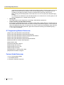
Introduction
About this Feature Guide
This Feature Guide is designed to serve as an overall feature reference for the Panasonic Hybrid IP-PBX.
It explains what this PBX can do, and how to obtain the most out of its many features and facilities.
This manual contains the following sections:
Section 1, Call Handling Features
Provides details about the call handling features.
Section 2, System Configuration and Administration Features
Provides details about the system configuration and administration features.
Section 3, Appendix
Provides tables listing capacity of system resources, exclusive features for each PBX model, tone and ring
tone tables, and the revision history of this Feature Guide.
Index
Provides feature titles and important words to help you access the required information easily.
Terms used in this Feature Guide
Installation Manual References
The required installation instruction titles described in the Installation Manual are noted for your reference.
PT Programming Manual References
The PT Programming titles described in the PT Programming Manual are noted for your reference.
Feature Guide References
The related feature titles described in this Feature Guide are noted for your reference.
User Manual References
The operation required to implement the feature described in the User Manual is noted for your reference.
Abbreviations
There are many abbreviations used in this manual (e.g., "PT", for proprietary telephone). Please refer to the
list in the next section for the meaning of each abbreviation.
About the other manuals
Along with this Feature Guide, the following manuals are available to help you install, and use this PBX:
Installation Manual
Provides instructions for installing the hardware and maintenance of the PBX.
PT Programming Manual
Provides step-by-step instructions for performing system programming using a PT.
2
Feature Guide
User Manual
Provides operating instructions for end users using PTs, SLTs, PSs, or DSS Consoles.
The KX-TDA30E, KX-TDA30NE, KX-TDA30GR, and KX-TDA30CE are designed to interwork with the:
Analogue Public Switched Telephone Network (PSTN) of European countries
Pan-European Integrated Services Digital Network (ISDN) using ISDN basic rate access
The KX-TDA100E/KX-TDA200E, KX-TDA100NE/KX-TDA200NE, KX-TDA100GR/KX-TDA200GR, and
KX-TDA100CE/KX-TDA200CE are designed to interwork with the:
Analogue Public Switched Telephone Network (PSTN) of European countries
Pan-European Integrated Services Digital Network (ISDN) using ISDN basic rate access
Pan-European Integrated Services Digital Network (ISDN) using ISDN primary rate access
ONP 2048 kbit/s digital structured leased lines (D2048S)
The KX-TDA600E, KX-TDA600NE, KX-TDA600GR, and KX-TDA600CE are designed to
interwork with the:
Analogue Public Switched Telephone Network (PSTN) of European countries
Pan-European Integrated Services Digital Network (ISDN) using ISDN basic rate access
Pan-European Integrated Services Digital Network (ISDN) using ISDN primary rate access
ONP 2048 kbit/s digital structured leased lines (D2048S)
Panasonic Communications Co., Ltd./Panasonic Communications Company (U.K.) Ltd. declares that this
equipment is in compliance with the essential requirements and other relevant provisions of Radio &
Telecommunications Terminal Equipment (R&TTE) Directive 1999/5/EC.
Declarations of Conformity for the relevant Panasonic products described in this manual are available for
download by visiting:
http://www.doc.panasonic.de
Contact:
Panasonic Services Europe
a Division of Panasonic Marketing Europe GmbH
Panasonic Testing Centre
Winsbergring 15, 22525 Hamburg, Germany
Trademarks
•
Microsoft, Windows, and Outlook are either registered trademarks or trademarks of Microsoft
Corporation in the United States and/or other countries.
•
Intel and Pentium are trademarks or registered trademarks of Intel Corporation or its subsidiaries
in the United States and other countries.
•
All other trademarks identified herein are the property of their respective owners.
Notes
•
•
The contents of this manual apply to PBXs with a certain software version, as indicated on the
cover of this manual. To confirm the software version of your PBX, refer to the FAQ in the On-line
Help of the Maintenance Console, or [190] Main Processing (MPR) Software Version Reference in
the PT Programming Manual.
Some optional service cards, PTs, and features are not available in some areas. In the same
respect, some optional service cards and features are available exclusively for the KX-TDA30, KXTDA100, KX-TDA200, or KX-TDA600. Please consult your certified Panasonic dealer for more
information.
→3.2 Exclusive Features Table
Feature Guide
3
•
•
•
•
4
Product specifications are subject to change without notice. In some cases, additional information,
including updates to this and other manuals, is included in the KX-TDA Maintenance Console's
Information Before Programming. Install the latest version of Maintenance Console to view this
information.
Throughout this manual, PT displays and other displays are shown in English. Other languages
may be available, depending on the country or area.
In this manual, the suffix of each model number (e.g., KX-TDA100NE) is omitted unless necessary.
All system programming can be performed through PC programming (→ 2.3.1 PC Programming).
However, only a subset can be performed through PT programming (→ 2.3.2 PT Programming).
In Section 1 Call Handling Features and Section 2 System Configuration and Administration
Features, programming references that include a three-digit number, such as "000" indicate that
system programming can be performed through PT programming.
For further details, please refer to the On-line Help of the Maintenance Console.
Feature Guide
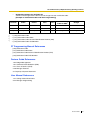
Feature Highlights
Networking Features
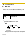
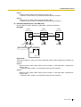
This PBX supports the following networking features:
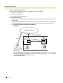
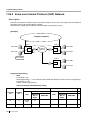
TIE Line Service
A TIE line is a privately leased communication line between two or more PBXs, which provides cost
effective communications between company members at different locations. (→ 1.29.1 TIE Line
Service)
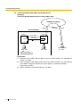
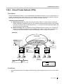
Virtual Private Network (VPN)
VPN is a service provided by the telephone company. It uses an existing public line as if it were a private
line. (→ 1.29.3 Virtual Private Network (VPN))
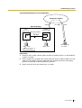
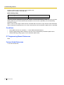
QSIG Network
QSIG is a protocol based on ISDN (Q.931) and offers enhanced PBX features in a private network of
two or more connected PBXs. (→ 1.29.4 QSIG Standard Features)
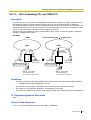
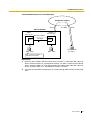
Voice over Internet Protocol (VoIP) Network
The PBX can connect to another PBX via a private IP network. In this case, voice signals are converted
into IP packets and sent through this network. Automatic rerouting of VoIP calls to public trunks is also
available, in case of network difficulties. (→ 1.29.2 Voice over Internet Protocol (VoIP) Network)
Built-in Small Call Centre Features
An incoming call distribution group (→ 1.2.2 Incoming Call Distribution Group Features) can be used as a
small call centre with the following features:
Queuing Feature
When a preprogrammed number of extensions in an incoming call distribution group are busy,
additional incoming calls can wait in a queue. While calls are waiting in the queue, the calls are handled
by the Queuing Time Table, which can be assigned for each time mode (day/lunch/break/night). (→
1.2.2.4 Queuing Feature)
Log-in/Log-out
Incoming call distribution group members can join (Log-in) or leave (Log-out) the groups manually.
While logged-in, a member extension can have a preprogrammed time period automatically for refusing
calls after completing the last call (Wrap-up). (→ 1.2.2.7 Log-in/Log-out)
VIP Call
It is possible to assign a priority to incoming call distribution groups. If an extension belongs to multiple
groups and the extension becomes idle, queuing calls in the groups will be distributed to the extension
in priority order. (→ 1.2.2.5 VIP Call)
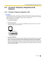
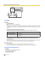
Computer Telephony Integration (CTI) Features
Connecting a PC to a DPT, or connecting a CTI Server to this PBX, allows functions of the PC, PBX and
extension to be integrated so that, for example, detailed caller information can be taken from a database
and displayed on the PC as a call arrives, or the PC can dial numbers for the extension automatically. (→
1.31.1 Computer Telephony Integration (CTI))
PC Phone/PC Console Features
This PBX supports PC Phone and PC Console. These Panasonic CTI applications provide advanced
features combining telephone and PC, such as the ability to display detailed caller information, including a
photograph, on the screen of the PC when a call is received, or to dial a telephone number automatically
just by selecting a name (1.31.2 PC Phone/PC Console).
Feature Guide
5
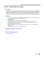
Voice Mail Features
This PBX supports Voice Processing Systems (VPS) with DTMF Integration as well as DPT (Digital)
Integration, attached locally and over a network. (→ 1.23 Voice Mail Features)
Parallelled Telephone Features
By connecting telephones in parallel, you can increase the number of telephones connected to the PBX
without adding additional extension cards. (→ 1.10.9 Parallelled Telephone)
Parallel Mode
An SLT can be connected to an APT or DPT that is connected to a Super Hybrid port of the PBX. The
SLT shares the same extension number with the APT or DPT.
EXtra Device Port (XDP) Mode
An SLT can be connected to a DPT that is connected to a Super Hybrid port of the PBX. Unlike parallel
mode, XDP mode allows each telephone to act as an independent extension with its own extension
number.
Digital XDP
A DPT can be connected to another DPT that is connected to a DPT port or a Super Hybrid port of the
PBX. Similar to XDP mode, each DPT acts as an independent extension with its own extension number.
Portable Station (PS) Features
PSs (e.g., KX-TCA255, KX-TD7690) can be connected to this PBX. It is possible to use the PBX features
using the PS like a PT. A PS can also be used in parallel with a wired telephone (Wireless XDP Parallel
Mode). In this case, the wired telephone is the main telephone and the PS is the sub telephone. (→ 1.24
Portable Station (PS) Features)
Hospitality Features
This PBX has several features that support its use in a hotel-type environment. Extensions corresponding
to guest rooms can be "checked in" or "checked out" by a designated hotel operator, who can also check or
set wake-up calls, and print out records of guest charges. (→ 1.26.1 Hospitality Features—SUMMARY)
Built-in Simplified Voice Message (SVM) Features
By just installing an optional voice message card in the PBX, simple answering machine services can be
provided. (→ 1.16.8 Built-in Simplified Voice Message (SVM))
Cellular Phone Features (KX-TDA6920/KX-TDA0920/KX-TDA3920 required)
This PBX supports the use of cellular phones and other outside destinations with the PBX. Cellular phones
can be treated as extensions within the PBX, and paired with wired telephones in Cellular Phone XDP
Parallel Mode. (→ 1.32.1 Cellular Phone Features—SUMMARY)
6
Feature Guide
List of Abbreviations
A
AA → Automated Attendant
ACD → Automatic Call Distribution
ANI → Automatic Number Identification
AOC → Advice of Charge
APT → Analogue Proprietary Telephone
ARS → Automatic Route Selection
B
BGM → Background Music
BRI → Basic Rate Interface
C
CCBS → Completion of Calls to Busy Subscriber
CF → Call Forwarding—by ISDN
CLI → Calling Line Identification
CLIP → Calling Line Identification Presentation
CLIR → Calling Line Identification Restriction
CNIP → Calling Name Identification Presentation
CNIR → Calling Name Identification Restriction
COLP → Connected Line Identification Presentation
COLR → Connected Line Identification Restriction
CONP → Connected Name Identification Presentation
CONR → Connected Name Identification Restriction
COS → Class of Service
CPC → Calling Party Control
CS → Cell Station
CT → Call Transfer—by ISDN
CTI → Computer Telephony Integration
D
DDI → Direct Dialling In
DID → Direct Inward Dialling
DIL → Direct In Line
DISA → Direct Inward System Access
DND → Do Not Disturb
DPT → Digital Proprietary Telephone
DSS → Direct Station Selection
DTMF → Dual Tone Multi-Frequency
E
EFA → External Feature Access
Feature Guide
7
F
FWD → Call Forwarding
G
G-CO → Group-CO
I
ICD → Incoming Call Distribution
IP-PT → IP Proprietary Telephone
IRNA → Intercept Routing—No Answer
ISDN → Integrated Services Digital Network
L
L-CO → Loop-CO
LCS → Live Call Screening
LED → Light Emitting Diode
M
MCID → Malicious Call Identification
MSN → Multiple Subscriber Number
N
NDSS → Network Direct Station Selection
O
OGM → Outgoing Message
OHCA → Off-hook Call Announcement
OPX → Off Premise Extension
P
P-MP → Point-to-multipoint
P-P → Point-to-Point
PIN → Personal Identification Number
PRI → Primary Rate Interface
PS → Portable Station
PT → Proprietary Telephone
S
S-CO → Single-CO
SLT → Single Line Telephone
SMDR → Station Message Detail Recording
SVM → Built-in Simplified Voice Message
T
TAFAS → Trunk Answer from Any Station
TEI → Terminal Endpoint Identifier
8
Feature Guide
TRG → Trunk Group
TRS/Barring → Toll Restriction/Call Barring
U
UCD → Uniform Call Distribution
V
VM → Voice Mail
VoIP → Voice over Internet Protocol
VPN → Virtual Private Network
VPS → Voice Processing System
X
XDP → EXtra Device Port
Feature Guide
9
Table of Contents
1
10
Call Handling Features......................................................................... 15
1.1
1.1.1
Incoming Call Features..................................................................................................16
Incoming Trunk Call Features ..........................................................................................16
1.1.1.1
1.1.1.2
1.1.1.3
1.1.1.4
1.1.1.5
1.1.1.6
1.1.1.7
Incoming Trunk Call Features—SUMMARY .................................................................................................... 16
Direct In Line (DIL) .......................................................................................................................................... 20
Direct Inward Dialling (DID)/Direct Dialling In (DDI) ........................................................................................ 22
Multiple Subscriber Number (MSN) Ringing Service ...................................................................................... 25
Calling Line Identification (CLI) Distribution..................................................................................................... 28
Intercept Routing ............................................................................................................................................. 30
Intercept Routing—No Destination .................................................................................................................. 33
1.1.2
Internal Call Features.......................................................................................................34
1.1.2.1
1.1.2.2
Internal Call Features—SUMMARY ................................................................................................................ 34
Internal Call Block............................................................................................................................................ 36
1.1.3
Incoming Call Indication Features .................................................................................... 38
1.1.3.1
1.1.3.2
1.1.3.3
Incoming Call Indication Features—SUMMARY ............................................................................................. 38
Ring Tone Pattern Selection ............................................................................................................................ 39
Call Waiting ..................................................................................................................................................... 41
1.2
1.2.1
1.2.2
Receiving Group Features ............................................................................................43
Idle Extension Hunting .....................................................................................................43
Incoming Call Distribution Group Features ......................................................................45
1.2.2.1
1.2.2.2
1.2.2.3
1.2.2.4
1.2.2.5
1.2.2.6
1.2.2.7
1.2.2.8
Incoming Call Distribution Group Features—SUMMARY................................................................................ 45
Group Call Distribution .................................................................................................................................... 49
Outside Destinations in Incoming Call Distribution Group............................................................................... 52
Queuing Feature.............................................................................................................................................. 54
VIP Call............................................................................................................................................................ 57
Overflow Feature ............................................................................................................................................. 58
Log-in/Log-out ................................................................................................................................................. 60
Supervisory Feature ........................................................................................................................................ 63
1.3
1.3.1
Call Forwarding (FWD)/Do Not Disturb (DND) Features .............................................65
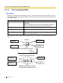
Call Forwarding (FWD)/Do Not Disturb (DND).................................................................65
1.3.1.1
1.3.1.2
1.3.1.3
1.3.1.4
Call Forwarding (FWD)/Do Not Disturb (DND)—SUMMARY .......................................................................... 65
Call Forwarding (FWD) .................................................................................................................................... 66
Do Not Disturb (DND)...................................................................................................................................... 70
FWD/DND Button, Group FWD Button............................................................................................................ 71
1.4
1.4.1
Answering Features.......................................................................................................74
Answering Features .........................................................................................................74
1.4.1.1
1.4.1.2
1.4.1.3
1.4.1.4
Answering Features—SUMMARY ................................................................................................................... 74
Line Preference—Incoming ............................................................................................................................. 75
Call Pickup....................................................................................................................................................... 76
Hands-free Answerback .................................................................................................................................. 78
1.5
1.5.1
1.5.2
1.5.3
1.5.4
Making Call Features .....................................................................................................79
Predialling ........................................................................................................................79
Automatic Extension Release ..........................................................................................80
Intercom Call ....................................................................................................................81
Trunk Call Features .......................................................................................................... 82
1.5.4.1
1.5.4.2
1.5.4.3
1.5.4.4
1.5.4.5
1.5.4.6
1.5.4.7
1.5.4.8
Trunk Call Features—SUMMARY.................................................................................................................... 82
Emergency Call ............................................................................................................................................... 83
Account Code Entry ........................................................................................................................................ 84
Dial Type Selection .......................................................................................................................................... 85
Reverse Circuit ................................................................................................................................................ 86
Trunk Busy Out ................................................................................................................................................ 87
Pause Insertion................................................................................................................................................ 88
Host PBX Access Code (Access Code to the Telephone Company from a Host PBX) .................................. 89
Feature Guide
1.5.4.9
Special Carrier Access Code...........................................................................................................................91
1.5.5
Seizing a Line Features................................................................................................... 92
1.5.5.1
1.5.5.2
1.5.5.3
Seizing a Line Features—SUMMARY .............................................................................................................92
Line Preference—Outgoing .............................................................................................................................93
Trunk Access ...................................................................................................................................................94
1.6
1.6.1
Memory Dialling Features............................................................................................. 96
Memory Dialling Features................................................................................................ 96
1.6.1.1
1.6.1.2
1.6.1.3
1.6.1.4
1.6.1.5
1.6.1.6
1.6.1.7
Memory Dialling Features—SUMMARY ..........................................................................................................96
One-touch Dialling ...........................................................................................................................................99
KX-T7710 One-touch Dialling ........................................................................................................................100
Last Number Redial .......................................................................................................................................101
Speed Dialling—Personal/System .................................................................................................................102
Quick Dialling .................................................................................................................................................104
Hot Line .........................................................................................................................................................105
1.7
1.7.1
1.7.2
1.7.3
1.7.4
Busy Line/Busy Party Features.................................................................................. 106
Automatic Callback Busy (Camp-on)............................................................................. 106
Executive Busy Override ............................................................................................... 107
Call Monitor ................................................................................................................... 108
Second Call Notification to Busy Extension................................................................... 109
1.7.4.1
1.7.4.2
1.7.4.3
1.7.4.4
Second Call Notification to Busy Extension—SUMMARY .............................................................................109
Call Waiting Tone ...........................................................................................................................................111
Off-hook Call Announcement (OHCA)...........................................................................................................112
Whisper OHCA ..............................................................................................................................................113
1.8
1.8.1
1.8.2
1.8.3
1.8.4
1.8.5
1.8.6
1.9
1.9.1
1.10
1.10.1
1.10.2
1.10.3
1.10.4
1.10.5
1.10.6
1.10.7
1.10.8
1.10.9
1.10.10
1.11
1.11.1
1.12
1.12.1
1.12.2
1.12.3
1.12.4
1.13
1.13.1
Toll Restriction (TRS)/Call Barring (Barring) Features ............................................ 114
Toll Restriction (TRS)/Call Barring (Barring).................................................................. 114
Budget Management ..................................................................................................... 119
Extension Dial Lock ....................................................................................................... 120
Dial Tone Transfer.......................................................................................................... 121
Walking COS ................................................................................................................. 122
Verification Code Entry .................................................................................................. 124
Automatic Route Selection (ARS) Features .............................................................. 126
Automatic Route Selection (ARS) ................................................................................. 126
Conversation Features................................................................................................ 131
Hands-free Operation .................................................................................................... 131
Off-hook Monitor............................................................................................................ 132
Mute............................................................................................................................... 133
Headset Operation ........................................................................................................ 134
Data Line Security ......................................................................................................... 135
Flash/Recall/Terminate .................................................................................................. 136
External Feature Access (EFA) ..................................................................................... 137
Trunk Call Limitation ...................................................................................................... 138
Parallelled Telephone .................................................................................................... 140
Calling Party Control (CPC) Signal Detection ............................................................... 143
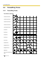
Transferring Features.................................................................................................. 144
Call Transfer................................................................................................................... 144
Holding Features ......................................................................................................... 146
Call Hold ........................................................................................................................ 146
Call Park ........................................................................................................................ 148
Call Splitting................................................................................................................... 149
Music on Hold................................................................................................................ 150
Conference Features................................................................................................... 152
Conference Features ..................................................................................................... 152
1.13.1.1
Conference Features—SUMMARY ...............................................................................................................152
Feature Guide
11
12
1.13.1.2
1.13.1.3
Conference .................................................................................................................................................... 153
Privacy Release............................................................................................................................................. 155
1.14
1.14.1
1.15
1.15.1
1.16
1.16.1
1.16.2
1.16.3
1.16.4
1.16.5
1.16.6
1.16.7
1.16.8
1.16.9
1.16.10
1.17
1.17.1
1.17.2
1.18
1.18.1
1.18.2
1.19
1.19.1
1.19.2
1.19.3
1.19.4
1.20
1.20.1
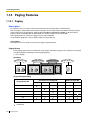
Paging Features ...........................................................................................................156
Paging ............................................................................................................................ 156
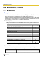
Broadcasting Features ................................................................................................158
Broadcasting ..................................................................................................................158
Optional Device Features ............................................................................................161
Doorphone Call ..............................................................................................................161
Door Open......................................................................................................................163
Trunk Answer From Any Station (TAFAS)....................................................................... 164
Background Music (BGM) ..............................................................................................165
Outgoing Message (OGM) ............................................................................................. 166
Direct Inward System Access (DISA).............................................................................169
Automatic Fax Transfer...................................................................................................177
Built-in Simplified Voice Message (SVM) ....................................................................... 179
External Sensor .............................................................................................................184
External Relay Control ...................................................................................................186
Caller ID Features.........................................................................................................188
Caller ID .........................................................................................................................188
Incoming Call Log ..........................................................................................................193
Message Features ........................................................................................................ 195
Message Waiting............................................................................................................195
Absent Message ............................................................................................................198
Proprietary Telephone (PT) Features ......................................................................... 199
Fixed Buttons ................................................................................................................. 199
Flexible Buttons..............................................................................................................202
LED Indication................................................................................................................205
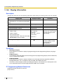
Display Information.........................................................................................................208
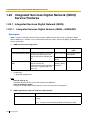
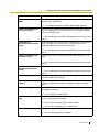
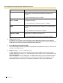
Integrated Services Digital Network (ISDN) Service Features .................................210
Integrated Services Digital Network (ISDN) ...................................................................210
1.20.1.1
1.20.1.2
1.20.1.3
1.20.1.4
1.20.1.5
1.20.1.6
1.20.1.7
1.20.1.8
1.20.1.9
1.20.1.10
1.20.1.11
1.20.1.12
Integrated Services Digital Network (ISDN)—SUMMARY............................................................................. 210
Calling/Connected Line Identification Presentation (CLIP/COLP)................................................................. 214
Advice of Charge (AOC)................................................................................................................................ 216
Call Forwarding (CF)—by ISDN (P-MP) ........................................................................................................ 217
Call Forwarding (CF)—by ISDN (P-P) ........................................................................................................... 219
Call Hold (HOLD)—by ISDN.......................................................................................................................... 221
Call Transfer (CT)—by ISDN ......................................................................................................................... 222
Three-party Conference (3PTY)—by ISDN ................................................................................................... 223
Malicious Call Identification (MCID)............................................................................................................... 224
Completion of Calls to Busy Subscriber (CCBS)........................................................................................... 225
ISDN Extension ............................................................................................................................................. 226
ISDN Service Access by Keypad Protocol .................................................................................................... 228
1.21
1.21.1
1.22
1.22.1
1.23
1.23.1
1.23.2
1.23.3
1.24
1.24.1
1.24.2
E1 Line Service Features............................................................................................. 229
E1 Line Service .............................................................................................................229
T1 Line Service Features............................................................................................. 231
T1 Line Service .............................................................................................................231
Voice Mail Features ...................................................................................................... 233
Voice Mail (VM) Group ...................................................................................................233
Voice Mail DTMF Integration ..........................................................................................236
Voice Mail DPT (Digital) Integration ...............................................................................242
Portable Station (PS) Features ...................................................................................247
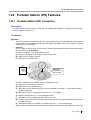
Portable Station (PS) Connection .................................................................................. 247
PS Ring Group ...............................................................................................................249
Feature Guide
1.24.3
1.24.4
1.24.5
1.24.6
1.25
1.25.1
1.25.2
1.25.3
1.26
1.26.1
1.26.2
1.26.3
1.27
1.27.1
1.27.2
1.27.3
1.27.4
1.28
1.28.1
1.28.2
1.29
1.29.1
1.29.2
1.29.3
1.29.4
PS Directory .................................................................................................................. 252
PS Feature Buttons ....................................................................................................... 253
Wireless XDP Parallel Mode.......................................................................................... 254
Virtual PS ...................................................................................................................... 257
Administrative Information Features......................................................................... 259
Station Message Detail Recording (SMDR) .................................................................. 259
Printing Message........................................................................................................... 266
Call Charge Services..................................................................................................... 267
Hospitality Features .................................................................................................... 270
Hospitality Features—SUMMARY ................................................................................. 270
Room Status Control ..................................................................................................... 271
Call Billing for Guest Room ........................................................................................... 273
Extension Controlling Features ................................................................................. 275
Extension Personal Identification Number (PIN) ........................................................... 275
Extension Feature Clear................................................................................................ 277
Walking Extension ......................................................................................................... 278
Timed Reminder ............................................................................................................ 279
Audible Tone Features ................................................................................................ 280
Dial Tone........................................................................................................................ 280
Confirmation Tone ......................................................................................................... 282
Networking Features ................................................................................................... 284
TIE Line Service ............................................................................................................ 284
Voice over Internet Protocol (VoIP) Network ................................................................. 306
Virtual Private Network (VPN) ....................................................................................... 309
QSIG Standard Features............................................................................................... 311
1.29.4.1
1.29.4.2
QSIG Standard Features—SUMMARY .........................................................................................................311
Calling/Connected Line Identification Presentation (CLIP/COLP) and Calling/Connected Name Identification
Presentation (CNIP/CONP)—by QSIG ..........................................................................................................313
Call Forwarding (CF)—by QSIG ....................................................................................................................315
Call Transfer (CT)—by QSIG .........................................................................................................................317
Completion of Calls to Busy Subscriber (CCBS)—by QSIG..........................................................................319
1.29.4.3
1.29.4.4
1.29.4.5
1.29.5
QSIG Enhanced Features ............................................................................................. 320
1.29.5.1
1.29.5.2
Network Direct Station Selection (NDSS)......................................................................................................320
Centralised Voice Mail ...................................................................................................................................325
1.29.6
Network ICD Group ....................................................................................................... 328
1.29.6.1
PS Roaming by Network ICD Group..............................................................................................................329
1.30
1.30.1
1.31
1.31.1
1.31.2
1.32
1.32.1
IP Proprietary Telephone (IP-PT) Features................................................................ 331
IP Proprietary Telephone (IP-PT) ................................................................................. 331
Computer Telephony Integration (CTI) Features ...................................................... 333
Computer Telephony Integration (CTI) .......................................................................... 333
PC Phone/PC Console .................................................................................................. 336
Cellular Phone Features ............................................................................................. 338
Cellular Phone Features—SUMMARY .......................................................................... 338
2
System Configuration and Administration Features .......................339
2.1
2.1.1
2.2
2.2.1
2.2.2
2.2.3
2.2.4
System Configuration—Hardware ............................................................................. 340
Extension Port Configuration......................................................................................... 340
System Configuration—Software .............................................................................. 342
Class of Service (COS) ................................................................................................. 342
Group............................................................................................................................. 344
Tenant Service............................................................................................................... 348
Time Service ................................................................................................................. 351
Feature Guide
13
2.2.5
2.2.6
2.3
2.3.1
2.3.2
2.3.3
2.3.4
2.3.5
2.3.6
2.3.7
2.3.8
2.4
2.4.1
2.4.2
2.4.3
3
Operator Features ..........................................................................................................355
Manager Features ..........................................................................................................356
System Data Control....................................................................................................358
PC Programming............................................................................................................358
PT Programming ............................................................................................................361
Password Security..........................................................................................................363
Quick Setup....................................................................................................................365
Automatic Setup .............................................................................................................366
Flexible Numbering/Fixed Numbering ............................................................................368
Floating Extension..........................................................................................................375
Software Upgrading .......................................................................................................377
Fault Recovery/Diagnostics ........................................................................................378
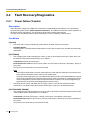
Power Failure Transfer....................................................................................................378
Power Failure Restart.....................................................................................................380
Local Alarm Information .................................................................................................381
Appendix ............................................................................................. 383
3.1
3.2
3.3
3.3.1
3.4
3.4.1
3.4.2
3.4.3
3.4.4
3.4.5
3.4.6
3.4.7
Capacity of System Resources...................................................................................384
Exclusive Features Table............................................................................................. 389
Tones/Ring Tones.........................................................................................................390
Tones/Ring Tones...........................................................................................................390
Revision History...........................................................................................................392
KX-TDA100/KX-TDA200 PMPR Software File Version 1.1xxx ...................................... 392
KX-TDA100/KX-TDA200 PMPR Software File Version 2.0xxx ...................................... 394
KX-TDA100/KX-TDA200/KX-TDA600 PMPR/PLMPR Software File Version 3.xxxx .....396
KX-TDA30 PSMPR Software File Version 1.1xxx ..........................................................398
KX-TDA30 PSMPR Software File Version 2.0xxx ..........................................................399
KX-TDA30 PSMPR Software File Version 2.2xxx ..........................................................401
KX-TDA30 PSMPR Software File Version 3.xxxx ..........................................................403
Index .......................................................................................................... 405
14
Feature Guide
Section 1
Call Handling Features
Feature Guide
15
1.1 Incoming Call Features
1.1
Incoming Call Features
1.1.1
Incoming Trunk Call Features
1.1.1.1
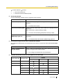
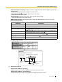
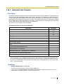
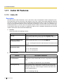
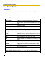
Incoming Trunk Call Features—SUMMARY
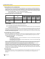
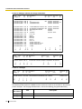
Description
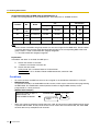
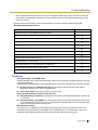
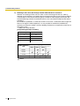
Incoming calls via a trunk (public line) are distributed to their destinations according to one of several
distribution methods.
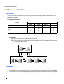
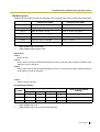
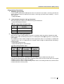
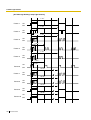
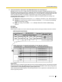
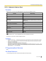
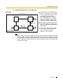
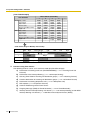
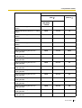
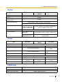
1. Available Networking Type for Each Optional Trunk Card Type
Each trunk port of an optional trunk card can be assigned a networking type: Public, Private, or VPN
(Virtual Private Network).
Networking Type
Trunk Card Type
Channel Type
Public (DIL/DID/
DDI/MSN)
ELCOT/LCOT
—
*
DID
—
*
T1
LCOT
*
GCOT
*
DID
*
TIE (E & M)
Private (TIE)*1
*
OPX (EXTN.)
E1
DR2
*
E & M-C
*
E & M-P
*
E&M
—
*
BRI/PRI
CO
*
Extension
IP-GW
16
Feature Guide
QSIG-Master
*
QSIG-Slave
*
—
*
Virtual Private
Network (VPN)*2
1.1 Incoming Call Features
*: Enable (default);
*1:
*2:
: Enable
→ 1.29.1 TIE Line Service
→ 1.29.3 Virtual Private Network (VPN)
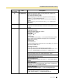
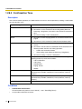
2. Distribution Method
One of the following methods can be assigned to each trunk port:
Method
Description & Reference
Direct In Line (DIL)
Directs a call to a preprogrammed single destination (e.g., the
operator).
→ 1.1.1.2 Direct In Line (DIL)
Direct Inward Dialling (DID)
Directs a call with a DID number from a DID line to a preprogrammed
destination.
DID is also known as Direct Dialling In (DDI).
→ 1.1.1.3 Direct Inward Dialling (DID)/Direct Dialling In (DDI)
Multiple Subscriber Number Directs a call with an MSN from an ISDN line to a preprogrammed
(MSN) Ringing Service
destination.
→ 1.1.1.4 Multiple Subscriber Number (MSN) Ringing Service
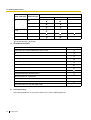
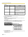
3. Destination Change with the Caller's Identification Number
The Calling Line Identification (CLI) Distribution feature works in conjunction with the DIL/DID/DDI/MSN
features.
Feature
Description & Reference
Calling Line Identification
(CLI) Distribution
Directs a call to a CLI destination if the caller's identification number
has been assigned in the Caller ID Table.
→ 1.1.1.5 Calling Line Identification (CLI) Distribution
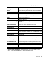
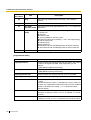
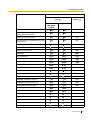
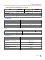
4. Available Distribution Feature for Each Optional Trunk Card Type
Feature
Trunk Card Type
Channel Type
DIL
ELCOT/LCOT
—
DID
—
T1
LCOT
*
GCOT
*
MSN
*
*
DID
TIE (E & M)
DID/DDI
*
*
Feature Guide
17
1.1 Incoming Call Features
Feature
Trunk Card Type
Channel Type
DIL
E1
DR2
DID/DDI
*
E & M-C
*
E & M-P
*
E&M
—
*
BRI
CO
*
PRI
CO
*
*: Enable (default);
MSN
: Enable
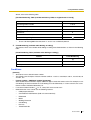
5. Available Destinations
Destination
Wired Extension (PT/SLT/ISDN Extension/T1-OPX)
PS
Incoming Call Distribution Group
PS Ring Group
Floating Extension no. for SVM
VM Group (DTMF/DPT)
External Pager (TAFAS)
DISA
Analogue/ISDN Remote Maintenance
Idle Line Access no. + Phone no.
Trunk Group Access no. + Trunk Group no. + Phone no.
Other PBX Extension (TIE with no PBX Code)
Other PBX Extension (TIE with PBX Code)
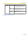
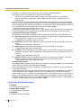
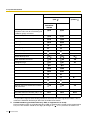
6. Intercept Routing
After setting distribution, it may also be necessary to set the following features.
18
Feature Guide
Availability
1.1 Incoming Call Features
Feature
Intercept Routing
No Answer (IRNA)
Description & Reference
If a called party does not answer a call within a
preprogrammed time period (Intercept time), it is
redirected to the preprogrammed destination.
→ 1.1.1.6 Intercept Routing
Busy/DND
If a called party is busy or in DND mode, the call is
redirected to the preprogrammed destination.
→ 1.1.1.6 Intercept Routing
No Destination
If a destination is not assigned, the call is redirected to
the operator.
→ 1.1.1.7 Intercept Routing—No Destination
PT Programming Manual References
None
Feature Guide
19
1.1 Incoming Call Features
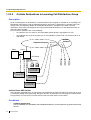
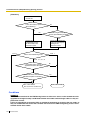
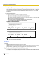
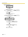
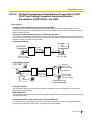
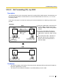
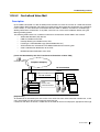
1.1.1.2
Direct In Line (DIL)
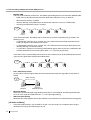
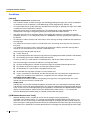
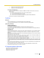
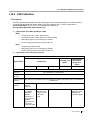
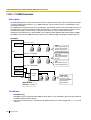
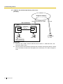
Description
Provides automatic direction of an incoming trunk call to a preprogrammed destination. Each trunk has a
destination for each time mode (day/lunch/break/night).
[Method Flowchart]
A trunk call is received.
Does the call have its CLI*
information and is CLI mode enabled
for the trunk and the time mode?
No
Yes
CLI works.
Yes
Is the CLI destination
assigned?
No
No
Is the DIL destination of
the time mode assigned?
Yes
The call is routed to the
CLI destination.
The call is routed to the
DIL destination.
The call is routed to the
operator (Intercept Routing
—No Destination).
*: Calling Line Identification (CLI) Distribution:
If the CLI routing is enabled and the caller's identification number is assigned in the Caller ID
Table, the call will not be routed to the DIL destination, but routed to the CLI destination.
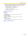
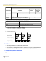
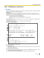
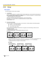
[Programming Example of DIL Table]
The table can be programmed for each trunk.
Destination*
CLI
Trunk No.
*:
20
Day
Lunch
...
Day
Lunch
...
01
Enable
Disable
...
101
100
...
02
Enable
Disable
...
102
100
...
:
:
:
:
:
:
:
→ [450] DIL 1:1 Destination
Feature Guide
1.1 Incoming Call Features
Note
Tenant number and VPS trunk group number can also be assigned in the DIL table. Tenant number is
used to determine the time mode (day/lunch/break/night) for the corresponding trunk. VPS trunk group
number is used in Voice Mail DPT (Digital) Integration.
Explanation:
If a trunk call is received from trunk 01;
In Day mode: CLI is enabled. Route to CLI destination.
In Lunch mode: CLI is disabled. Route to DIL destination, extension 100.
PT Programming Manual References
[421] BRI DIL/DDI/MSN Selection
[450] DIL 1:1 Destination
Feature Guide References
1.1.1.5 Calling Line Identification (CLI) Distribution
2.2.3 Tenant Service
2.2.4 Time Service
3.1 Capacity of System Resources
Feature Guide
21
1.1 Incoming Call Features
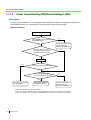
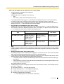
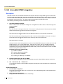
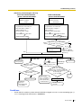
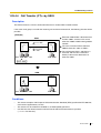
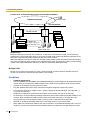
1.1.1.3
Direct Inward Dialling (DID)/Direct Dialling In (DDI)
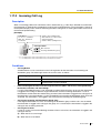
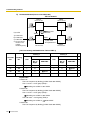
Description
Provides automatic direction of an incoming call with a DID/DDI number to a preprogrammed destination.
Each DID/DDI number has a destination for each time mode (day/lunch/break/night).
[Method Flowchart]
A trunk call is received.
Is the DID/DDI number found in
the DID/DDI table?
No
The call is routed to the
operator (Intercept
Routing—No Destination).
Yes
Does the call have its CLI*
information and is CLI mode
enabled for the time mode?
No
Yes
CLI works.
Yes
Is the CLI destination assigned?
No
Is the DID/DDI destination
for the time mode assigned?
No
Yes
The call is routed to the
CLI destination.
The call is routed to the
DID/DDI destination.
The call is routed to the
operator (Intercept
Routing—No Destination).
*: Calling Line Identification (CLI) Distribution:
If the CLI routing is enabled and the caller's identification number is assigned in the Caller ID
Table, the call will not be routed to the DID/DDI destination, but routed to the CLI destination.
22
Feature Guide
1.1 Incoming Call Features
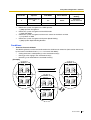
[Programming Example of DID/DDI Table]
DDI can be programmed as DID.
No.*1
Location
*1:
*2:
*3:
Destination*3
CLI
Name*2
Day
Lunch
...
Day
Lunch
...
0001
123-4567
John White
Enable
Disable
...
105
100
...
0002
123-2468
Tom Smith
Enable
Disable
...
102
100
...
0003
123-456
A company
Enable
Disable
...
101
101
...
:
:
:
:
:
:
:
:
:
→ [451] DID Number
→ [452] DID Name
→ [453] DID Destination
Note
Tenant number and VPS trunk group number can also be assigned in the DID/DDI table. Tenant number
is used to determine the time mode (day/lunch/break/night) for the corresponding DID/DDI number.
VPS trunk group number is used in Voice Mail DPT (Digital) Integration (→ 1.23.3 Voice Mail DPT
(Digital) Integration).
Explanation:
If the DID/DDI number is "123-4567":
1. Checks the number in the table.
→ Matches the number in location 0001.
2. Checks the time mode.
In Day mode: CLI is enabled. Route to CLI destination.
In Lunch mode: CLI is disabled. Route to DID/DDI destination, extension 100.
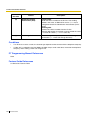
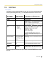
Conditions
•
•
To use this feature, DID/DDI service must be assigned as the distribution method for a trunk port.
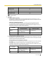
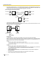
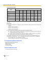
DID/DDI Number Modification
It is possible to modify a received DID/DDI number, which may be convenient when programming the
DID/DDI table. The modification method (removed number of digits/added number) can be
programmed on a trunk port basis.
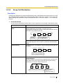
[Modification Example]
Removed number of digits: 6
Modified DID/DDI number: 876543 21 = 1021
Added number: 10
Received DID/DDI number: 87654321
1) Remove the
first 6 digits.
2) Add "10".
Feature Guide
23
1.1 Incoming Call Features
•
Inter-digit Time
When the Inter-digit time expires, the PBX stops receiving the DID/DDI number and starts to check the
DID/DDI table. (Refer to the [Programming Example of DID/DDI Table] above).
Even if the Inter-digit time does not expire, the PBX stops receiving the DID/DDI number when the
received number is found in the DID/DDI table. The PBX then routes the call to the corresponding
destination. If the received number matches several entries in the table, the call is directed to the
destination of the first matching entry.
[Example] If a call is received in Lunch mode;
Received Number
Destination
Explanation
123-4567
Extn. 100
The PBX finds the match in location 0001 in the table
after receiving "7". So the call is routed to extension 100.
123-456
Extn. 101
The Inter-digit time expired after receiving "6". The PBX
finds the match in location 0003 in the table. So the call
is routed to extension 101.
PT Programming Manual References
[421] BRI DIL/DDI/MSN Selection
[451] DID Number
[452] DID Name
[453] DID Destination
Feature Guide References
1.1.1.5 Calling Line Identification (CLI) Distribution
2.2.3 Tenant Service
2.2.4 Time Service
3.1 Capacity of System Resources
24
Feature Guide
1.1 Incoming Call Features
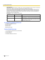
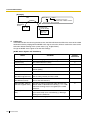
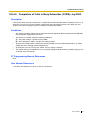
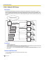
1.1.1.4
Multiple Subscriber Number (MSN) Ringing Service
Description
Provides automatic direction of an incoming ISDN-BRI (Basic Rate Interface) line call with an MSN to a
preprogrammed destination. One ISDN-BRI port can support a maximum of 10 MSNs. Each MSN has a
destination for each time mode (day/lunch/break/night).
Point-to-multipoint must be selected for the ISDN configuration.
[Method Flowchart]
A trunk call is received.
Are any MSNs assigned
in the MSN table?
Yes
Is the MSN found in the
MSN table?
Yes
Does the call have its CLI*
information and is CLI mode
enabled for the time mode?
No
The call is routed to the
operator (Intercept
Routing—No Destination).
No
The call is ignored.
No
Yes
CLI works.
Yes
Is the CLI destination
assigned?
No
Is the MSN destination for
the time mode assigned?
No
Yes
The call is routed to the
CLI destination.
The call is routed to the
MSN destination.
The call is routed to the
operator (Intercept
Routing—No Destination).
*: Calling Line Identification (CLI) Distribution:
If the CLI routing is enabled and the caller's identification number is assigned in the Caller ID
Table, the call will not be routed to the MSN destination, but routed to the CLI destination.
Feature Guide
25
1.1 Incoming Call Features
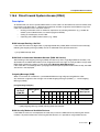
[Programming Example of MSN Table for ISDN BRI Port 1]
A table can be programmed for each ISDN-BRI port. Each BRI port has 10 MSN locations.
CLI
Location
No.
Destination
Name
Day
Lunch
...
Day
Lunch
...
01
1234567
A Company
Enable
Disable
...
101
100
...
02
1232468
C Company
Enable
Disable
...
102
100
...
:
:
:
:
:
:
:
:
:
10
:
:
:
:
:
:
:
:
Note
Tenant number and VPS trunk group number can also be assigned in the MSN table. Tenant number
is used to determine the time mode (day/lunch/break/night) for the corresponding MSN. VPS trunk
group number is used in Voice Mail DPT (Digital) Integration.
→ 1.23.3 Voice Mail DPT (Digital) Integration
Explanation:
If the MSN "123-4567" is received from BRI port 1:
1. Checks the number in the table.
→ Matches the number in location 01.
2. Checks the time mode.
In Day mode: CLI is enabled. Route to CLI destination.
In Lunch mode: CLI is disabled. Route to MSN destination, extension 100.
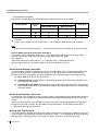
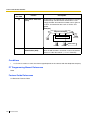
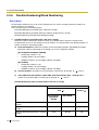
Conditions
•
•
To use this feature, the MSN service must be assigned as the distribution method for a trunk port.
MSN Modification
It is possible to modify a received MSN to make it shorter, which may be convenient when programming
the MSN table. The modification method (removed number of digits/added number) can be
programmed on a trunk port basis.
[Modification Example]
Removed number of digits: 6
Added number: 10
Received MSN: 87654321
•
26
Modified MSN: 876543 21 = 1021
1) Remove the first
6 digits.
2) Add "10".
When using point-to-multipoint configuration with a BRI, do not connect another ISDN terminal device
in parallel with the PBX. As only two channels can be used at one time with the BRI, the other ISDN
terminal device may monopolise both channels.
Feature Guide
1.1 Incoming Call Features
PT Programming Manual References
[421] BRI DIL/DDI/MSN Selection
[426] BRI Configuration
Feature Guide References
1.1.1.5 Calling Line Identification (CLI) Distribution
2.2.3 Tenant Service
2.2.4 Time Service
3.1 Capacity of System Resources
Feature Guide
27
1.1 Incoming Call Features
1.1.1.5
Calling Line Identification (CLI) Distribution
Description
Directs an incoming trunk call to a preprogrammed destination when the caller's identification number (e.g.,
Caller ID) matches the number in the System Speed Dialling Table that is used as the Caller ID Table. Each
Caller ID number (telephone number for each System Speed Dialling number) can have its own destination.
CLI Feature
Description & Reference
Caller ID
Caller's number is sent from an analogue trunk.
→ 1.17.1 Caller ID
Calling Line Identification
Presentation (CLIP)
Caller's number is sent from an ISDN line.
→ 1.20.1.2 Calling/Connected Line Identification Presentation (CLIP/
COLP)
Automatic Number Identification
(ANI)
Caller's number is sent from an E1 or T1 line.
→ 1.21.1 E1 Line Service
→ 1.22.1 T1 Line Service
CLI always works in conjunction with the following call distribution methods:
a) DIL
b) DID/DDI
c) MSN Ringing Service
Each trunk (for DIL) and the DID/DDI/MSN number can enable or disable the CLI feature for each time mode
(day/lunch/break/night) (→ 2.2.4 Time Service).
When the call has Caller ID information and the CLI is enabled for the time mode, the call will be handled
by the CLI method.
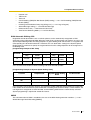
[Programming Example of System Speed Dialling Table for CLI]
Location
(System Speed Dialling
No.)
Telephone No.*1
System Speed Dialling
Name*2
CLI Destination
000
901234567890
ABC Company
200
001
:
:
:
:
:
:
:
*1:
*2:
28
→ [001] System Speed Dialling Number
→ [002] System Speed Dialling Name
Feature Guide
1.1 Incoming Call Features
Explanation:
If the caller's number is "0123-456-7890" (The Trunk Access number is disregarded):
1. Checks the number in the table.
→ Matches the number in location 000.
2. The call is routed to the CLI destination, extension 200.
Conditions
•
Automatic Caller ID Number Modification
The Caller ID number is used after modification by the Automatic Caller ID Number Modification. (→
1.17.1 Caller ID)
PT Programming Manual References
[001] System Speed Dialling Number
[002] System Speed Dialling Name
Feature Guide References
1.1.1.2 Direct In Line (DIL)
1.1.1.3 Direct Inward Dialling (DID)/Direct Dialling In (DDI)
1.1.1.4 Multiple Subscriber Number (MSN) Ringing Service
1.6.1.5 Speed Dialling—Personal/System
Feature Guide
29
1.1 Incoming Call Features
1.1.1.6
Intercept Routing
Description
Provides automatic redirection of incoming trunk calls. There are two types of Intercept Routing as follows:
Feature
Description
Intercept Routing—No Answer
(IRNA)
If a called party does not answer a call within a preprogrammed time
period (Intercept time), the call is redirected to the preprogrammed
destination.
Intercept Routing—Busy/DND
If a called party is busy or in DND mode, the call is redirected to the
preprogrammed destination.
The intercept destinations used are as follows:
Type 1:
The assigned intercept destination of the extension port.
→ [604] Extension Intercept Destination
The assigned intercept destination of the trunk group that received the call.
→ [470] Trunk Group Intercept Destination
Type 2:
Original Destination
Intercept Destination
Wired Extension (PT/SLT/ISDN
Extension/T1-OPX)
Type 1
PS
Type 1
Incoming Call Distribution Group
Intercept Routing—Overflow for the Incoming Call Distribution
Group is used (→ 1.2.2.6 Overflow Feature). The call is
redirected to the overflow destination assigned for the incoming
call distribution group.
→ [625] Destination for Overflow Time Expiration
30
PS Ring Group
Type 2
Floating Extension no. for SVM
Not available
VM Group (DTMF/DPT)
Type 2
External Pager (TAFAS)
Type 2
DISA
Type 2*
Analogue/ISDN Remote Maintenance
Not available
Idle Line Access no. + Phone no.
Not available
Trunk Group Access no. + Trunk Group
no. + Phone no.
Not available
Other PBX Extension (TIE with no PBX
Code)
Not available
Other PBX Extension (TIE with PBX
Code)
Not available
Feature Guide
1.1 Incoming Call Features
*: This is applied only when a trunk call arrives on a DISA line but the line is busy at that time. Once the
call reaches the destination extension by using the DISA feature, the Intercept Routing feature of the
extension is used.
Different intercept destinations can be programmed for each time mode (day/lunch/break/night).
[Available Intercept Destinations]
Intercept Destination
Availability
Wired Extension (PT/SLT/ISDN Extension/T1-OPX)
PS
Incoming Call Distribution Group
PS Ring Group
Floating Extension no. for SVM
VM Group (DTMF/DPT)
External Pager (TAFAS)
DISA
Analogue/ISDN Remote Maintenance
Idle Line Access no. + Phone no.
Trunk Group Access no. + Trunk Group no. + Phone no.
Other PBX Extension (TIE with no PBX Code)
Other PBX Extension (TIE with PBX Code)
Conditions
•
Intercept Routing—Busy/DND on/off
Intercept Routing—Busy and Intercept Routing—DND can be enabled or disabled separately through
system programming.
If disabled, one of the following is activated depending on the trunk card type that a call arrives through:
a) ELCOT, LCOT, or T1 (LCOT/GCOT) Card: The incoming trunk call will ring at the original
destination while the caller hears a ringback tone.
b) Other Trunk Cards: A busy tone will be sent to the caller.
•
If the intercept destination cannot receive the call:
a) Intercept Routing—No Answer: Intercept timer will restart at the original destination, until the call
is answered.
b) Intercept Routing—Busy/DND: The call will be sent back to the original destination when the call
•
arrives through the ELCOT, LCOT or T1 (LCOT/GCOT) card. When the call arrives through other
trunk cards the caller will hear a busy tone.
Idle Extension Hunting
If an extension is a member of an idle extension hunting group, calls to that extension will not be
redirected by Intercept Routing—Busy/DND. If the extension is busy or in DND mode, calls to that
extension will be redirected to the next extension in the idle extension hunting group.
Feature Guide
31
1.1 Incoming Call Features
PT Programming Manual References
[203] Intercept Time
[470] Trunk Group Intercept Destination
[604] Extension Intercept Destination
[625] Destination for Overflow Time Expiration
Feature Guide References
1.3.1 Call Forwarding (FWD)/Do Not Disturb (DND)
32
Feature Guide
1.1 Incoming Call Features
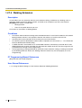
1.1.1.7
Intercept Routing—No Destination
Description
Provides automatic redirection of incoming trunk calls that do not have a destination assigned. The intercept
destination is an operator (tenant/PBX).
Conditions
•
•
•
Intercept Routing—No Destination on/off
The Intercept Routing—No Destination feature can be enabled or disabled through system
programming.
If disabled, a reorder tone will be sent to the caller. However, the Intercept Routing—No Destination
feature always functions for calls through the ELCOT, LCOT, or T1 (LCOT/GCOT) card even when
disabled.
If an operator (tenant/PBX) is not assigned:
The extension connected to the lowest-numbered jack will be the intercept destination.
Intercept Routing—No Destination also applies to calls from doorphones.
PT Programming Manual References
[006] Operator Assignment
Feature Guide References
2.2.5 Operator Features
Feature Guide
33
1.1 Incoming Call Features
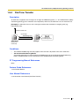
1.1.2
Internal Call Features
1.1.2.1
Internal Call Features—SUMMARY
Description
The following types of internal calls are available:
Feature
Description & Reference
Intercom Call
A call from one extension to another.
→ 1.5.3 Intercom Call
Doorphone Call
When a call from a doorphone reaches its destination, the recipient
can talk to the visitor.
→ 1.16.1 Doorphone Call
[Available Destination]
The destinations of doorphone calls can be assigned for each time mode (day/lunch/break/night) (→ 2.2.4
Time Service) on a doorphone port basis.
Calling from
Destination
Extension
Wired Extension (PT/SLT/ISDN Extension/T1-OPX)
PS
Incoming Call Distribution Group
PS Ring Group
Floating Extension no. for SVM
VM Group (DTMF/DPT)
External Pager (TAFAS)
DISA
Analogue/ISDN Remote Maintenance
Idle Line Access no. + Phone no.
Trunk Group Access no. + Trunk Group no. + Phone no.
Other PBX Extension (TIE with no PBX Code)
Other PBX Extension (TIE with PBX Code)
: Available
34
Feature Guide
Doorphone
1.1 Incoming Call Features
PT Programming Manual References
[720] Doorphone Call Destination
Feature Guide
35
1.1 Incoming Call Features
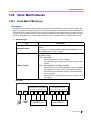
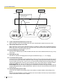
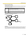
1.1.2.2
Internal Call Block
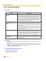
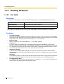
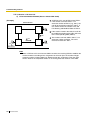
Description
Internal calls can be restricted on a COS basis. This is done by specifying which COS destinations are
blocked for each COS.
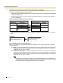
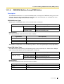
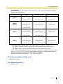
[Programming Example]
Called Party
Caller
COS 1
COS 2
COS 3
...
:
:
:
:
COS 1
COS 2
COS 3
:
: Block
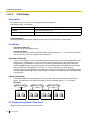
Explanation:
a) COS 1 extensions can make calls to all extensions.
b) COS 2 extensions can make calls to COS 1 destinations only. (COS 2 extensions cannot make
calls to COS 2 destinations.)
c) COS 3 extensions can make calls to COS 3 destinations only.
COS 1
Extn. 100
Extn. 101
COS 2
Extn. 102
COS 3
Extn. 103
Extn. 104
Extn. 105
Extn. 106
Conditions
•
•
•
36
Restricted extension numbers cannot be used as the parameter of a feature setting (e.g., FWD)
All extensions can make an Operator Call (→ 2.2.5 Operator Features) regardless of Internal Call Block.
This feature can also restrict calling a doorphone from an extension on the basis of the COSs assigned
to the extension and doorphone port. (→ 1.16.1 Doorphone Call)
Feature Guide
1.1 Incoming Call Features
PT Programming Manual References
None
Feature Guide References
2.2.1 Class of Service (COS)
Feature Guide
37
1.1 Incoming Call Features
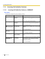
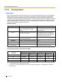
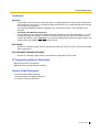
1.1.3
1.1.3.1
Incoming Call Indication Features
Incoming Call Indication Features—SUMMARY
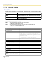
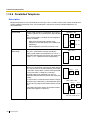
Description
Incoming calls are indicated by various methods as follows:
Type
Ring Tone
Feature
Ring Tone Pattern
Selection
Description & Reference
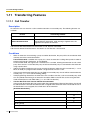
A telephone rings when receiving a call. The ring
tone patterns can be changed for each incoming call
type.
→ 1.1.3.2 Ring Tone Pattern Selection
Voice-calling
Alternate Receiving—
Ring/Voice
A PT user can select to receive intercom calls by ring
tone or by voice, through personal programming.
→ 1.5.3 Intercom Call
LED
(Light Emitting Diode)
LED Indication
The light shows line conditions with a variety of light
patterns.
→ 1.19.3 LED Indication
Display (Caller's
Information)
Display Information
The display shows the caller's information.
→ 1.19.4 Display Information
External Pager
Trunk Answer from Any The external pager sends a ring tone when receiving
Station (TAFAS)
a call.
→ 1.16.3 Trunk Answer From Any Station (TAFAS)
Tone/Voice during a
Conversation
Call Waiting
A busy extension hears a tone, or voice from the
handset/built-in speaker indicating that another
incoming call is waiting.
→ 1.1.3.3 Call Waiting
38
Feature Guide
1.1 Incoming Call Features
1.1.3.2
Ring Tone Pattern Selection
Description
It is possible to select the type of ring tone pattern that arrives at an extension for each type of incoming call,
etc.
[Ring Tone Patterns]
1 280 ms*
Single
Double
Triple
S-Double
*: The duration of a ring tone may vary by country/area.
[Ring Tone Pattern Table]
The ring tone pattern table is categorised into three parts, each containing a specified number of pattern
plans.
The ring tone pattern table is categorised as follows:
•
•
•
Incoming Trunk Calls: each pattern plan can assign a ring tone pattern for each trunk group.
Incoming Doorphone Calls: each pattern plan can assign a ring tone pattern for each doorphone.
Others: each pattern plan can assign a ring tone pattern for incoming intercom calls as well as ring
tones assigned to certain features (e.g., timed reminder).
The ring tone patterns that arrive at an extension are determined by the pattern plan that is assigned to that
extension through system programming.
[Programming Example of Ring Tone Pattern Table]
Intercom
Call/Hold
Recall
Trunk Call/Hold
Recall
Doorphone Call
TRG1
Port 1
1
Double
Single
Single
2
Single
Double
Double
:
:
:
Table
No.
TRG2 ...
:
:
:
Timed
Reminder
Call Back
LCS
External
Sensor
:
:
:
:
Port 2 ...
:
:
Conditions
•
"PT Ring off Setting" can be enabled or disabled through system programming. If disabled, PT
users cannot turn incoming call ringing off for their extension.
Feature Guide
39
1.1 Incoming Call Features
PT Programming Manual References
None
Feature Guide References
3.1 Capacity of System Resources
40
Feature Guide
1.1 Incoming Call Features
1.1.3.3
Call Waiting
Description
Used to inform a busy extension that another incoming call is waiting. The busy extension user can answer
the second call by disconnecting the current call or placing it on hold.
The following notification method can be assigned for each extension depending on the call waiting and the
telephone type:
a)
b)
c)
d)
Call Waiting Tone: Tone from the handset or built-in speaker
OHCA: Voice from the built-in speaker
Whisper OHCA: Voice from the handset
Off: No notification.
Notification Method
Call Type
DPT
Intercom Call
Call Waiting tone/OHCA/
Whisper OHCA/Off
Trunk Call*
Call Waiting tone/Off
Other Telephone
Call Waiting tone/Off
*: Including a doorphone call, call via an incoming call distribution group, and a trunk call transferred from
another extension.
This feature is also known as Busy Station Signalling (BSS).
Conditions
•
•
•
•
•
Call Waiting call for an extension in a VM group (DPT/DTMF) is not available.
Data Line Security
Setting Data Line Security cancels the Call Waiting setting. (→ 1.10.5 Data Line Security)
Call Waiting Tone
A PT user can hear different Call Waiting tones for trunk call and intercom call if "Tone 2" has been
selected through personal programming (Call Waiting Tone Type Selection). If "Tone 1" has been
selected, the same Call Waiting tone will be heard for both trunk call and intercom call.
All Call Waiting tone patterns have a default (→ 3.3.1 Tones/Ring Tones).
Caller Information
With the Call Waiting tone, the caller's information flashes on the display for five seconds, followed by
a 10-second pause, then flashes again for five seconds.
Call Waiting from the Telephone Company
Besides the Call Waiting service within the PBX, the Call Waiting tone offered by an analogue line from
the telephone company informs the extension user of another incoming trunk call that is waiting. He can
answer the second call by disconnecting the current call or placing it on hold using EFA. For details,
consult your telephone company.
Call Waiting Caller ID (Visual Caller ID):
When using the call waiting tone supplied by the telephone company over analogue lines, the waiting
caller's telephone number can be received. The number will flash on the display for five seconds,
followed by a 10-second pause, then flash again for five seconds.
Note that the received caller information will not be displayed on telephones or wireless phones
connected to SLT ports.
Feature Guide
41
1.1 Incoming Call Features
PT Programming Manual References
None
Feature Guide References
1.7.4 Second Call Notification to Busy Extension
1.17.2 Incoming Call Log
1.25.1 Station Message Detail Recording (SMDR)
User Manual References
1.4.4 Answering Call Waiting
1.7.3 Receiving Call Waiting (Call Waiting/Off-hook Call Announcement [OHCA]/Whisper OHCA)
3.1.2 Settings on the Programming Mode
42
Feature Guide
1.2 Receiving Group Features
1.2
Receiving Group Features
1.2.1
Idle Extension Hunting
Description
If a called extension is busy or in DND mode, Idle Extension Hunting redirects the incoming call to an idle
member of the same idle extension hunting group, which can be programmed through system programming.
Idle extensions are automatically searched according to a preprogrammed hunting type.
This feature is also known as Station Hunting.
Type
Circular Hunting
Description
An idle extension is searched for in the order specified in the idle
extension hunting group in a circular way.
Incoming call
Busy
Extn.
Extn.
Extn.
Extn.
Assigned order
Terminated Hunting
An idle extension is searched for in the order specified in the idle
extension hunting group until reaching the last assigned extension.
Incoming call
Extn.
Busy
Extn.
Extn.
Extn.
Assigned order
Conditions
•
•
•
Idle Extension Hunting applies to:
Intercom, trunk, and doorphone calls to a single destination.
An extension user can belong to only one idle extension hunting group.
If all the searched extensions are busy:
The PBX redirects the call to an overflow destination which can be assigned for each idle extension
hunting group and each time mode (day/lunch/break/night) (→ 2.2.4 Time Service).
[Available Destination]
Destination
Availability
Wired Extension (PT/SLT/ISDN Extension/T1-OPX)
PS
Incoming Call Distribution Group
Feature Guide
43
1.2 Receiving Group Features
Destination
Availability
PS Ring Group
VM Group (DTMF/DPT)
External Pager (TAFAS)
DISA
Analogue/ISDN Remote Maintenance
Idle Line Access no. + Phone no.
Trunk Group Access no. + Trunk Group no. + Phone no.
Other PBX Extension (TIE with no PBX Code)
Other PBX Extension (TIE with PBX Code)
•
FWD/DND Mode
While searching for an idle extension within an idle extension hunting group, any extension that has set
FWD—All Calls or DND feature will be skipped, and the call will go to the next extension in the group.
PT Programming Manual References
[680] Idle Extension Hunting Type
[681] Idle Extension Hunting Group Member
Feature Guide References
1.3.1 Call Forwarding (FWD)/Do Not Disturb (DND)
3.1 Capacity of System Resources
44
Feature Guide
1.2 Receiving Group Features
1.2.2
Incoming Call Distribution Group Features
1.2.2.1
Incoming Call Distribution Group Features—SUMMARY
Description
An incoming call distribution group is a group of extensions programmed through system programming.
→ [620] Incoming Call Distribution Group Member
An incoming call distribution group receives calls directed to the group. Each incoming call distribution group
has a floating extension number (default: 6 + two-digit group number).
Incoming calls directed to an incoming call distribution group are distributed to the member extensions in
the group using a distribution method. When a preprogrammed number of extensions in the group are busy,
the incoming calls can wait in a queue.
Each incoming call distribution group and member extensions can be programmed as desired to handle
incoming calls. Calls to the group can be monitored by an extension assigned as a supervisor.
Programming Item Example for Incoming Call Distribution Group 1 with
Diagram
A through F in the table are described in the following diagram.
A
C
Max.
No. of
Group Floating Group
Distribution
Busy
No. Extn. No.*1 Name*2
Method*3
Extensions*4
1
601
Sales
Ring
3
2
602
Engineering UCD
Max.
3
:
*1:
*2:
*3:
*4:
*5:
*6:
*7:
*8:
*9:
B
D
Queuing
Call
Capacity*5
5
11
E
F
Hurry-up Overflow Overflow Destination*8
... ... Night
Level*6 Time*7
Day
... ... 100
100
3
60
... ... 200
200
8
90
Tenant
No.*9
1
5
→ [622] Incoming Call Distribution Group Floating Extension Number
→ [623] Incoming Call Distribution Group Name
→ [624] Incoming Call Distribution Group Distribution Method
→ [632] Maximum Number of Agents
→ [628] Queuing Call Capacity
→ [629] Queuing Hurry-up Level
→ [626] Overflow Time
→ [625] Destination for Overflow Time Expiration/[627] Destination When All Busy
The tenant number is required to determine the time mode (day/lunch/break/night) (→ 2.2.4 Time
Service) and the music source (for Music on Hold) for each group.
Feature Guide
45
1.2 Receiving Group Features
Calls arriving at incoming call
distribution group 1.
9
8
F Overflow Feature
a) Sends a busy tone (Busy on Busy), or
b) Redirects to the overflow destination.
7
6
D Queuing Feature
5
Five calls are
waiting in a queue.
4
3
B Group Call Distribution
Calls are distributed by the
assigned method.
(Only three extensions
[agents] can answer the
call for C Busy on Busy.)
2
1
E Manual Queue Redirection *10
The longest waiting call in a queue
can be redirected to the overflow
destination by pressing the Hurry-up
button. The button shows the Hurryup status.
Supervisor Extension*11
Extn.
100
Extn.
101
Monitors or controls the
incoming call distribution
group status.
Extn.
102
Extn.
103
Extn.
104
A Incoming Call
Extn.
105
Log-in
Extn.
105
Log-out *12
Distribution Group 1
(Floating extension no.: 601;
Name: Sales)
→ 1.2.2.4 Queuing Feature
→ 1.2.2.8 Supervisory Feature
*12: → 1.2.2.7 Log-in/Log-out
*10:
*11:
1. Group Call Distribution [→ 1.2.2.2 Group Call Distribution]
Incoming calls are distributed using one of the following methods:
Distribution Method
Description
Uniform Call Distribution
(UCD)
Calls are distributed evenly to a different extension each time a call is
received.
Priority Hunting
An idle extension is searched for in the specified order, always
starting from the same location.
Ring
All extensions in the incoming call distribution group ring
simultaneously.
2. Queuing Feature [→ 1.2.2.4 Queuing Feature]
If a preprogrammed numbers of extensions in an incoming call distribution group are busy, a
preprogrammed number of additional calls can wait in a queue.
While calls are waiting in the queue, an outgoing message (OGM) or Music on Hold can be sent to the
waiting callers.
46
Feature Guide
1.2 Receiving Group Features
3. VIP Call [→ 1.2.2.5 VIP Call]
It is possible to assign a priority to incoming call distribution groups so that incoming calls can be
received in priority order.
4. Overflow Feature [→ 1.2.2.6 Overflow Feature]
A call is redirected to a preprogrammed destination when it cannot be answered or queued (Intercept
Routing—Overflow in an Incoming Call Distribution Group). It is also possible to send a busy tone
(Busy on Busy) or disconnect the line.
5. Incoming Call Distribution Group Controlling Feature
Feature
Log-in/Log-out
Description & Reference
Member extensions can join the group to handle
calls (Log-in) or leave the group for a break (Logout).
They can leave the group temporarily when they are
away from their desks, to prevent calls being sent to
their extensions.
→ 1.2.2.7 Log-in/Log-out
Supervisory
Feature
Incoming Call Queue
Monitor
The supervisor extension can monitor various
information about the incoming calls for each
incoming call distribution group on his display.
→ 1.2.2.8 Supervisory Feature
Log-in/Log-out
Monitor and Remote
Control
Monitor: The supervisor extension can monitor the
log-in/log-out status of the group members.
Remote Control: The supervisor extension can
change the status of the members.
→ 1.2.2.8 Supervisory Feature
Conditions
•
•
One extension can belong to multiple incoming call distribution groups.
ICD Group button
An Incoming Call Distribution (ICD) Group button can be assigned on a flexible button for each incoming
call distribution group. It receives the incoming calls to the group.
One extension can have more than one ICD Group button of the same or different incoming call
distribution groups (Multiple ICD Group). If all ICD Group buttons in the same incoming call distribution
group are occupied, the next incoming call will be held in a queue or will overflow. If the ICD Group
button is not assigned, incoming calls will arrive at the INTERCOM or CO button.
The mode of ICD Group buttons can be selected through system programming, as follows:
– Standard Mode (ICD Group Button Mode)
An extension can have an ICD Group button for an incoming call distribution group that the
extension does not belong to through system programming. However, the ICD Group button will
not receive calls to that group.
– Enhanced Phantom Button Mode
An extension can join an ICD Group just by creating a button for that group, even if the extension
was not previously registered as a member. When the button is created, the extension will be
Feature Guide
47
1.2 Receiving Group Features
•
•
automatically registered in the lowest-numbered available member slot for the group. Calls to the
group can be received at the extension with no further programming. If no member slots are
available for that group, the button cannot be created and an alarm tone will be heard.
When creating an ICD Group button in this mode, the user can also specify the delayed ringing
settings.
If an extension user deletes the last ICD Group button at his extension for a certain group, he will
also be deregistered as a member from that group.
Group FWD
The FWD feature can be assigned on an incoming call distribution group basis.
COS for Incoming Call Distribution Groups
Each incoming call distribution group is assigned a COS number. Group FWD to an outside party can
be enabled or disabled for each COS. The COS for incoming call distribution groups is also used for the
Internal Call Block feature; when an extension user calls an incoming call distribution group, the PBX
checks the COS of the calling extension against the COS of the incoming call distribution group (→
1.1.2.2 Internal Call Block).
PT Programming Manual References
[620] Incoming Call Distribution Group Member
[621] Incoming Call Distribution Group Delayed Ringing
[622] Incoming Call Distribution Group Floating Extension Number
[623] Incoming Call Distribution Group Name
[624] Incoming Call Distribution Group Distribution Method
[625] Destination for Overflow Time Expiration
[626] Overflow Time
[627] Destination When All Busy
[628] Queuing Call Capacity
[629] Queuing Hurry-up Level
[630] Queuing Time Table
[631] Sequences in Queuing Time Table
[632] Maximum Number of Agents
Feature Guide References
1.3.1.2 Call Forwarding (FWD)
1.19.2 Flexible Buttons
3.1 Capacity of System Resources
48
Feature Guide
1.2 Receiving Group Features
1.2.2.2
Group Call Distribution
Description
Incoming calls directed to an incoming call distribution group are distributed to the member extensions using
the selected distribution method until a preprogrammed number of extensions (agents) are busy with calls.
When incoming calls exceed the number of available extensions, calls enter a queue (→ 1.2.2.4 Queuing
Feature).
1. Distribution Method
One of the three distribution methods below can be assigned to each incoming call distribution group.
Distribution Method
Uniform Call Distribution
(UCD)
Description
Calls are distributed evenly to a different extension each time a call is
received. Extensions are hunted in a circular way in the
preprogrammed order for the group, starting at the extension after the
extension that received the last call.
Received
the last call.
Extn.
D
Extn.
C
Extn.
B
Extn.
A
Starts searching from
extn. B. (Skips extn. A.)
Depending on system programming, calls can be directed to the
longest idle extension. This is known as Automatic Call Distribution
(ACD).
Priority Hunting
An idle extension is searched for using the preprogrammed order for
the group.
1st Priority
2nd Priority 3rd ....
Extn.
B
Extn.
A
Extn.
C
Extn.
D
Always starts searching from
the first assigned extension.
Ring
All extensions in the group ring simultaneously.
Delayed Ringing:
Delayed ringing or no ringing can be programmed for each extension
in the group. The call can be answered by pressing the flashing
button even if no ring or a delayed time is set.
Extn.
A
Extn.
B
Extn.
C
Rings immediately simultaneously.
Extn.
D
Delayed Ringing:
Rings after a
specified time delay.
Feature Guide
49
1.2 Receiving Group Features
2. Call Waiting for Incoming Call Distribution Group (Group Call Waiting)
When there are no available extensions in an incoming call distribution group, the group members can
receive the Call Waiting tone. To use this feature:
•
Select the Group Call Waiting mode through system programming. This determines the distribution
method for waiting calls.
•
Member extensions must assign the Call Waiting mode individually, or they will not be notified. (→
1.1.3.3 Call Waiting)
[How the Group Call Waiting Feature Activates]
Programming Conditions
Result
Group Call
Group Call
Waiting Mode Distribution Method
Distribution
UCD
Priority Hunting
Ring
All
UCD/Priority Hunting/
Ring
Group Call Waiting
Capable
Distribution Method
Telephone
PT/PS with idle
UCD
ICD Group button
Priority Hunting
Any telephone
Not available*
Ring
*: Incoming calls enter the queue immediately. Member extensions do not receive the Call Waiting
tone.
[Example]
• Group Call Waiting mode: All
• Group call distribution method
for idle extensions: UCD
All extensions hear the Call
Waiting tone (Ring).
[ICD Group Button for Group Call Waiting]
The way that the Group Call Waiting feature works depends on the Group Call Waiting Distribution
method as follows:
a) Ring: The Group Call Waiting feature activates for all busy member extensions (even when
the extensions do not have ICD Group buttons) simultaneously for only one incoming call—
additional calls will wait in a queue.
b) UCD/Priority Hunting: The Group Call Waiting feature activates on an idle ICD Group button
located on busy member extensions in a certain order. (This order depends on the type: UCD
or Priority Hunting.) Calls will arrive at idle buttons until all ICD Group buttons are occupied—
additional calls will wait in a queue.
Note
In method b), if an extension has one or more ICD Group buttons for an incoming call
distribution group and all the ICD Group buttons on the extension are occupied, the Group
Call Waiting feature for the group will not work at the extension.
50
Feature Guide
1.2 Receiving Group Features
Incoming Call
Distribution
Group 1
(Floating
extension
no.: 601)
3
2
Incoming Call
Distribution
Group 2
(Floating
extension
no.: 602)
1
ICD Group 1; 601 (Call Waiting)
ICD Group 1; 601 (Call Waiting)
ICD Group 2; 602 (Answering the Call)
3. No Reply Redirection (UCD or Priority Hunting Method)
If a call received at a member extension is not answered within a preprogrammed time period (No
Answer time), the call will be redirected to the next member extension. If there is no idle group member,
the call queues at the target extension until a group member becomes available.
Conditions
•
•
•
Automatic Call Distribution (ACD)
– When a KX-TDA6920, KX-TDA0920 or KX-TDA3920 SD Memory Card for Software Upgrade to
Enhanced Version is installed in the PBX, and the distribution type is set to Uniform Call
Distribution, it is possible to select whether incoming calls are distributed to idle extensions evenly
in order (UCD), or to the extension that has been idle the longest (ACD).
– ACD does not work for ISDN extensions or PS Ring Groups.
FWD/DND Extension
System programming for each incoming call distribution group is required to skip or ring extensions
which have the FWD or DND feature set. If set to ring, the FWD/DND settings are ignored. (→ 1.3.1
Call Forwarding (FWD)/Do Not Disturb (DND))
The Group Call Waiting feature cannot be used with the VIP Call feature (→ 1.2.2.5 VIP Call) and/or
Wrap-up feature (→ 1.2.2.7 Log-in/Log-out). To use the VIP Call feature and/or Wrap-up feature, Call
Waiting mode on each extension should be off.
PT Programming Manual References
[621] Incoming Call Distribution Group Delayed Ringing
[624] Incoming Call Distribution Group Distribution Method
[632] Maximum Number of Agents
Feature Guide
51
1.2 Receiving Group Features
1.2.2.3
Outside Destinations in Incoming Call Distribution Group
Description
Up to 4 outside parties or destinations at another PBX can be assigned as members of an Incoming Call
Distribution (ICD) Group, using the following method: A virtual PS is registered as a member of the ICD
Group. Then, the telephone number of the outside destination is specified as the FWD—All Calls
destination. Calls to the ICD Group will also ring at the outside destination as if that destination were an
extension within the PBX.
This is useful in situations such as the following:
•
An extension user can have his PT and multiple cellular phones ring together for calls.
•
An employee who is not in the office, but is still available to answer calls, can receive calls to an
ICD Group.
Telephone Company
PBX-2
Cellular
Company
PBX-1
TIE
ICD Group
Virtual PS 1
Virtual PS 4
Virtual PS 2
Virtual PS 3
Cellular Phone XDP Parallel
The extension registered first in an ICD Group can programme the Forward settings for trunk calls to up to
4 virtual PSs through PT programming. Using this feature, an extension user can assign his cellular phone
to ring with his PT, so that he can easily receive trunk calls even when not at his desk.
Conditions
•
52
Hardware Requirement
The KX-TDA6920, KX-TDA0920 or KX-TDA3920 SD Memory Card for Software Upgrade to Enhanced
Version
Feature Guide
1.2 Receiving Group Features
•
•
•
•
•
•
•
•
•
For this feature to be activated, the following conditions must be met:
– A virtual PS is assigned as a member of the ICD Group. (→ 1.24.6 Virtual PS)
– The forwarding type of the virtual PS is set to All Calls. (→ 1.3.1.2 Call Forwarding (FWD))
– The forwarding destination is an outside party, including an extension at another PBX in the
network.
– FWD to trunk is allowed through COS programming for the virtual PSs.
– The distribution method for the ICD Group is set to Ring. (→ 1.2.2.2 Group Call Distribution)
Up to 4 virtual PSs can be assigned to a single ICD Group. If more than 4 are assigned, the 4 virtual
PSs with the lowest member numbers are available.
ELCOT/LCOT trunks without reverse circuit detection (→ 1.5.4.5 Reverse Circuit) and channels of a T1
trunk set to LCOT type do not support this feature.
Calls to an ICD Group will ring at a virtual PS even if all of the other extensions assigned to the group
are busy.
If all members of an ICD Group are virtual PSs, and trunk lines are available but the called parties are
all busy, neither the queuing or overflow features will operate. Therefore, it is recommended that at least
one PT or SLT is also assigned to an ICD Group.
To log in to or out of a group, a virtual PS user can access the PBX through DISA, enter the Walking
COS feature number (if required), and access log-in/log-out settings.
Delayed ringing can be assigned for virtual PSs in the same way as for other extensions.
The wrap-up time feature is not available for virtual PSs.
When forwarding calls to a public trunk, system programming selects whether the CLIP number of the
calling party or of the virtual PS is sent to the forward destination.
When calling using a private network, the CLIP number of the calling party will always be sent.
PT Programming Manual References
[620] Incoming Call Distribution Group Member
[621] Incoming Call Distribution Group Delayed Ringing
[622] Incoming Call Distribution Group Floating Extension Number
[624] Incoming Call Distribution Group Distribution Method
[690] PS Registration
Feature Guide References
1.24.6 Virtual PS
1.29.6 Network ICD Group
Feature Guide
53
1.2 Receiving Group Features
1.2.2.4
Queuing Feature
Description
When a preprogrammed number of extensions in an incoming call distribution group are busy, additional
incoming calls can wait in a queue. The number of calls which can wait in the queue is programmable.
While calls are waiting in the queue, the calls are handled by the Queuing Time Table, which can be
assigned for each time mode (day/lunch/break/night) (→ 2.2.4 Time Service). This PBX supports a specified
number of Queuing Time Tables which each have a specified number of sequences (specific commands
which are performed when a caller enters a queue). The following commands can be assigned to each
sequence when making a Queuing Time Table:
[Command Table]
Command
OGM xx
b×5s
Sequence c
Overflow
Disconnect
None
(No command)
Description
Condition
An outgoing message is sent to the
caller. "xx" applies to the OGM
number.
After the OGM, Music on Hold will be
sent and the next event in the sequence
will be activated.
Puts the caller in the waiting queue for If an OGM has not been sent to the
b (01-16) × 5 seconds.
caller, the caller hears a ringback tone.
If an OGM has been sent to the caller,
the caller hears Music on Hold.
Redirects to sequence c. "c" applies
to the sequence number.
None
Redirects to the overflow destination. None
Disconnects the line.
None
Redirects to the next sequence.
If assigned as sequence 01, the Queuing
Time Table will not be activated.
[Programming Example of Queuing Time Table]
Sequence*1
Queuing Time
Table No.
Sequence 01
Sequence 02
Sequence 03
Sequence 04
01
OGM 01
6×5s
OGM 03
Overflow
02*2
OGM 02
6×5s
OGM 04
None
:
:
:
:
...
03
:
*1:
*2:
54
→ [631] Sequences in Queuing Time Table
If a call has not reached a destination by the time the final sequence is completed, the call will be
disconnected.
Feature Guide
:
1.2 Receiving Group Features
Explanation for Queuing Time Table 01:
Queuing Time Table 01
The call
queues.
Sequence 01
OGM 01 is sent.
Thank you for
calling Panasonic.
The department you
are calling is busy.
Please hold the line.
We will answer your
call shortly.
Sequence 02
Music on Hold
is sent for 30
seconds.
Sequence 03
OGM 03 is sent.
We are sorry to
keep you holding.
The department
is still busy. We
are transferring
you to the
operator.
Sequence 04
Redirects to
the overflow
destination.
Overflow
destination
answers.
The call is connected to the member
extension as soon as the extension
becomes available.
Conditions
•
•
•
If the call is transferred to the incoming call distribution group and is handled by the Queuing
Time Table:
Transfer Recall will not occur even if the Transfer Recall time expires.
Manual Queue Redirection
It is possible to redirect the longest waiting call in a queue to the overflow destination by pressing the
Hurry-up button. (If the call is already ringing at an extension, it will not be redirected.)
This feature is also known as Hurry-up Transfer.
Hurry-up Button
A flexible button can be customised as the Hurry-up button. The number of calls queuing before Manual
Queue Redirection may be performed is programmable. The button shows the current status as follows:
Light Pattern
Calls in the Waiting Queue
Off
No queued call
Red on
At or under the assigned number for Hurry-up
Rapid red flashing
Over the assigned number for Hurry-up
PT Programming Manual References
[628] Queuing Call Capacity
[629] Queuing Hurry-up Level
[630] Queuing Time Table
[631] Sequences in Queuing Time Table
[632] Maximum Number of Agents
Feature Guide References
1.2.2.6 Overflow Feature
1.19.2 Flexible Buttons
3.1 Capacity of System Resources
Feature Guide
55
1.2 Receiving Group Features
User Manual References
1.8.3 Forwarding a Waiting Call (Manual Queue Redirection)
56
Feature Guide
1.2 Receiving Group Features
1.2.2.5
VIP Call
Description
It is possible to assign a priority to incoming call distribution groups. If an extension belongs to multiple
groups and the extension becomes idle, queuing calls in the groups will be distributed to the extension in
priority order.
Each incoming call distribution group can enable or disable the VIP Call mode. When multiple groups enable
the VIP Call mode, the incoming call distribution group with the lowest numbered group has the highest
priority. When multiple groups disable the VIP Call mode, queuing calls are distributed to extensions
uniformly.
[Example]
In the call centre, incoming call distribution groups 1 and 3 enable the VIP Call mode, while incoming call
distribution groups 2 and 4 disable the VIP Call mode.
Calls have been distributed by DIL/DID/DDI/CLI.
(The number in the circle is the queuing order.)
Incoming Call
Distribution
Group 1
(for VIP)
6
1
Incoming Call
Distribution
Group 2
(for general
customers)
Incoming Call
Distribution
Group 3
(for special
customers)
5
3
3rd
Priority
1st
Priority
Extn.
101
Extn.
102
4
2
2nd
Priority
Incoming Call
Distribution
Group 4
(for general
customers)
8
7
3rd
Priority
Extn.
103
Distribution order: 1
6
2
4
From: Group 1 Group 3
3
5
7
8
Groups 2 and 4
PT Programming Manual References
None
Feature Guide
57
1.2 Receiving Group Features
1.2.2.6
Overflow Feature
Description
When waiting calls exceed the waiting queue capacity, they may be redirected to a preprogrammed
destination or a busy tone may be sent to the callers by the following features:
1) Intercept Routing—Overflow in an Incoming Call Distribution Group
2) Busy on Busy
1. Intercept Routing—Overflow in an Incoming Call Distribution Group
Intercept Routing—Overflow in an Incoming Call Distribution Group works in one of following
conditions:
a)
b)
c)
d)
e)
There is no space in the waiting queue.
The Queuing Time Table is not assigned and there are no extensions logged in.
An Overflow command is assigned to the Queuing Time Table.
The Overflow time expires.
Manual Queue Redirection is performed.
[Available Destination]
The overflow destinations can be assigned for each incoming call distribution group and each time
mode (day/lunch/break/night) (→2.2.4 Time Service). The destination can be assigned as follows,
depending on the above conditions.
•
For a) and b):
→ [627] Destination When All Busy
•
For c), d), and e):
→ [625] Destination for Overflow Time Expiration
Destination
Wired Extension (PT/SLT/ISDN Extension/T1-OPX)
PS
Incoming Call Distribution Group
PS Ring Group
Floating Extension no. for SVM
VM Group (DTMF/DPT)
External Pager (TAFAS)
DISA
Analogue/ISDN Remote Maintenance
Idle Line Access no. + Phone no.
Trunk Group Access no. + Trunk Group no. + Phone no.
Other PBX Extension (TIE with no PBX Code)
Other PBX Extension (TIE with PBX Code)
58
Feature Guide
Availability
1.2 Receiving Group Features
2. Busy on Busy
The Busy on Busy feature works when the destination for the Intercept Routing—Overflow in an
Incoming Call Distribution Group feature is not assigned in one of the following conditions:
a) There is no space in the Waiting queue.
b) The Queuing Time Table is not assigned and there are no extensions logged-in.
[Example of a)]
There are five assistants in a shop. When the answering agent number is "2", and the queuing call
number is "0":
If two of the assistants are talking on the phone, the next caller will hear a busy tone to prevent the caller
from thinking that there is no one in the shop or that the shop is closed.
Conditions
[Intercept Routing—Overflow in an Incoming Call Distribution Group]
•
If the Overflow time expires, and the overflow destination is unavailable:
a) If the trunk call arrives through the ELCOT, LCOT or T1 (LCOT/GCOT) card:
(1) If the call was once in a queue and an outgoing message (OGM) was sent to it, or the call
reached an incoming call distribution group by using the DISA feature (→ 1.16.6 Direct Inward
System Access (DISA)): The line is disconnected.
(2) In all other cases: Redirection is ignored and the Overflow timer activates again.
b) If the call arrives through another card: Redirection is ignored and the Overflow timer activates
again.
[Busy on Busy]
•
If a trunk call arrives through the ELCOT, LCOT or T1 (LCOT/GCOT) card, a busy tone will not be sent
to the caller.
PT Programming Manual References
[625] Destination for Overflow Time Expiration
[626] Overflow Time
[627] Destination When All Busy
[628] Queuing Call Capacity
[632] Maximum Number of Agents
Feature Guide References
1.2.2.4 Queuing Feature
Feature Guide
59
1.2 Receiving Group Features
1.2.2.7
Log-in/Log-out
Description
Members of an incoming call distribution group can join (Log-in) or leave (Log-out) the group manually.
They can leave the group temporarily when they are away from their desks, to prevent calls being sent to
their extensions. They can return to the group when they are ready to answer calls.
Wrap-up:
While logged in, a member extension can have a preprogrammed time period automatically for refusing calls
after completing the previous call (Wrap-up time). While the Wrap-up timer is active, calls to all incoming
call distribution groups to which the extension belongs will skip the extension so that the extension user can
perform necessary tasks such as reporting on the previous call.
Wrap-up mode can also be activated manually (Not Ready) by pressing the Wrap-up button.
[Log-in/Log-out and Wrap-up Status Example]
<When the incoming call distribution group is in Priority Hunting distribution method>
Incoming call
Ready
Log-in
Waiting for a call
Press the
Wrap-up button.
Extn.
101
Extn.
102
Ready
Extn.
103
Extn.
104
Extn.
105
Extn.
106
Answering a call
The Wrap-up
time expires.
Not Ready
Making a report/
temporary break
Ready Not Ready Wrap-up Ready
After
completing
the call
Press the
Wrap-up button.
Wrap-up
Making a report
Extn.
102
Log-out
Conditions
•
•
It is programmable whether the last remaining logged-in extension can log out.
Log-in/Log-out Button
A flexible button can be customised as the Log-in/Log-out button with the following parameters:
Light Pattern
Parameter
Usage
Red on
No parameter
Used with an ICD Group button, or with —
the floating extension number of an
incoming call distribution group, or with
(All).
Floating extension number of a Used to log in to or out of the specified Log-out
specified incoming call
incoming call distribution group.
Status
distribution group
60
Feature Guide
Off
—
Log-in Status
1.2 Receiving Group Features
Light Pattern
Parameter
Usage
Red on
Used to log in to or out of all incoming After Log-out After Log-in
call distribution groups to which the
Operation
Operation
extension user belongs.
(All)
•
•
•
If an ICD Group button is assigned, it also shows the log-in/log-out status of the corresponding group.
The light pattern is the same as the Log-in/Log-out button that includes the group number.
Wrap-up Timer
– Two wrap-up timers can be programmed, an ICD Group member wrap-up timer and an extension
wrap-up timer. System programming selects which timer is used. When the ICD Group member
wrap-up timer is selected, the timer is only activated after calls to the extension through an ICD
Group. When the extension wrap-up timer is selected, the timer is activated after all calls to or from
the extension, including a retrieved call on hold.
– Only calls from ICD Groups cannot be received during the wrap-up time. Other calls are received
as normal.
– The wrap-up timer does not work for ISDN extensions or PS Ring Groups.
Wrap-up Button
A flexible button can be customised as the Wrap-up button. It shows the current status as follows:
Light pattern
•
•
•
•
Off
Status
Slow red flashing
Wrap-up
Red on
Not Ready
Off
Ready (Wrap-up mode cancel)
When a PS in Wireless XDP Parallel Mode completes a call, neither the PS nor its wired telephone can
have Wrap-up time. (→ 1.24.5 Wireless XDP Parallel Mode)
Automatic Log-out
A member extension may be logged out automatically, if the Unanswered time expires a
preprogrammed number of times consecutively. The number of consecutive unanswered calls can be
assigned for each incoming call distribution group. If the extension is a member of more than one
incoming call distribution group, the unanswered number is counted across all corresponding incoming
call distribution groups. It is possible to return to log-in mode manually.
The Automatic Log-out feature does not work for extensions in an incoming call distribution group using
the Ring distribution method (→ 1.2.2.2 Group Call Distribution).
Log-in/Log-out Monitor
The supervisor extension can monitor and control the log-in/log-out status of the incoming call
distribution group members. (→ 1.2.2.8 Supervisory Feature)
Log-in/Log-out Information on SMDR
Log-in/Log-out information can be printed out on SMDR. (→ 1.25.1 Station Message Detail Recording
(SMDR))
PT Programming Manual References
None
Feature Guide References
1.19.2 Flexible Buttons
Feature Guide
61
1.2 Receiving Group Features
User Manual References
1.8.1 Leaving an Incoming Call Distribution Group (Log-in/Log-out, Wrap-up)
62
Feature Guide
1.2 Receiving Group Features
1.2.2.8
Supervisory Feature
Description
An extension preprogrammed as a supervisor (supervisor extension) can monitor and control each
member's status within the incoming call distribution group using a 6-line display PT.
Feature
Description
Incoming Call Queue Monitor
The supervisor extension can monitor the status of an incoming call
distribution group with the display.
Log-in/Log-out Monitor and
Remote Control
Monitor: The supervisor extension can monitor the log-in/log-out
status of the incoming call distribution group members through the
corresponding DSS button light.
Remote Control: The supervisor extension can change the status of
the members by pressing the corresponding DSS button.
[Example]
<Incoming Call Queue Monitor Display>
31 Jan. 08:13AM FRI
601:Sales Section
Waiting Calls Now :00006
Max. Waiting Time :05'10
EXIT
LOG
--- Date and time
--- Floating extension number/name of incoming call distribution group
--- The number of queuing calls
--- The longest queuing time
SPRVS
Since 29 JAN. 09:10AM --- Monitoring starting date and time
Total Calls
:00996 --- Total number of incoming calls
Overflow Calls
:00131 --- Total number of overflowed calls
Lost Calls
:00039 --- The number of lost calls
Average Waiting
:02'12 --- Average queuing time
EXIT
CLEAR
<Log-in/Log-out Monitor/Remote Control Mode with DSS Button light>
31 Jan. 08:13AM FRI
601:Sales Section
Waiting Calls Now :00006
Max. Waiting Time :05'10 With
EXIT
Log-in/Log-out Monitor
DSS buttons of the incoming call
distribution group members show
their status.
Log-in/Log-out Remote Control
Pressing the button changes
the status as follows:
Light pattern
Status
Status
Light pattern
Green on
Log-in (Ready)
Log-out
Red on
Slow Green Flashing Log-in (Not Ready)
Red on
Log-out
Off
Extension in another
incoming call distribution
group
Log-in (Ready) Green on
Feature Guide
63
1.2 Receiving Group Features
Conditions
•
Available Extension as a Supervisor Extension
a) One supervisor extension can be assigned for each incoming call distribution group, but it need not
belong to the group.
b) One extension can be the supervisor extension of more than one incoming call distribution group.
•
•
•
•
Available Paired DSS Console
This feature is available for the KX-T7640, KX-T7440, and KX-T7441.
Accumulation Value Clear
Accumulation value data (total incoming calls, total overflowed calls, lost calls, average queuing time)
can be cleared manually. The date and time of clearing is saved and is shown on the display (monitoring
starting date and time). When the value exceeds 99999 before clearing, "****" will be shown.
If a call to an incoming call distribution group is overflowed:
If the display is in idle status, it will change to monitor mode for the corresponding incoming call
distribution group automatically.
If the display is monitoring another incoming call distribution group, it will not change.
Other Features while in Monitor Mode
The supervisor can use other features on the extension (making calls, pressing the MESSAGE button,
etc.) even while in monitor mode. When each operation is finished, his telephone returns to the queue
monitor display.
PT Programming Manual References
None
User Manual References
1.8.2 Monitoring and Controlling the Call Status of an Incoming Call Distribution Group (Incoming Call
Distribution Group Monitor)
64
Feature Guide
1.3 Call Forwarding (FWD)/Do Not Disturb (DND) Features
1.3
Call Forwarding (FWD)/Do Not Disturb (DND)
Features
1.3.1
Call Forwarding (FWD)/Do Not Disturb (DND)
1.3.1.1
Call Forwarding (FWD)/Do Not Disturb (DND)—SUMMARY
Description
When an extension user cannot answer calls (e.g., he is busy, or not at his desk), it is possible to forward or
refuse calls using the following features:
1) Call Forwarding (FWD)
2) Do Not Disturb (DND)
1. FWD
Extensions and incoming call distribution groups can forward their incoming calls to preset destinations.
(→ 1.3.1.2 Call Forwarding (FWD))
2. DND
Callers to an extension will hear a tone to inform them that the extension user is not available. (→
1.3.1.3 Do Not Disturb (DND))
3. FWD/DND Button, Group FWD Button
The FWD/DND fixed button, or a customised flexible button, can display the FWD/DND setting status
of the extension. (→ 1.3.1.4 FWD/DND Button, Group FWD Button)
Conditions
•
FWD and DND are set for intercom calls (including doorphone calls), and trunk calls (including a call
from an extension that placed a trunk call on a consultation hold) separately.
Feature Guide
65
1.3 Call Forwarding (FWD)/Do Not Disturb (DND) Features
1.3.1.2
Call Forwarding (FWD)
Description
Extensions and incoming call distribution groups can forward their calls to preset destinations. There are
several different types of forwarding, and the circumstances under which the calls are forwarded for each
type differ as follows:
Type
Circumstance
All Calls
Any time
Follow Me:
When an extension user fails to set this feature before leaving the
desk, this feature can be set from the destination extension.
Busy
When the extension user's line is busy.
No Answer
When the extension user does not answer within a preprogrammed
time.
Busy/No Answer
When the extension user's line is busy or the user does not answer
within a preprogrammed time.
Depending on the type of incoming intercom or trunk calls, it is possible to set a different destination for
each.
Intercom Calls
to Extension
Extension
Forwards to
Another Extension
Forwards to
Outside Party
Trunk Calls to
Extension
Available Forwarding Type: All Calls
Busy
No Answer
Busy/No Answer
Incoming Call Distribution Group
Intercom Calls to
Incoming Call
Distribution Group
Forwards to
Another Extension
Trunk Calls to
Incoming Call
Distribution Group
Forwards to
Outside Party
Available Forwarding Type: All Calls
66
Feature Guide
1.3 Call Forwarding (FWD)/Do Not Disturb (DND) Features
[Available Destinations]
Destination
Wired Extension (PT/SLT/ISDN Extension/T1OPX)
PS
Availability
Condition for Original Extension/
Incoming Call Distribution Group
Only available when FWD to
extension is allowed through COS
programming.*
Incoming Call Distribution Group
PS Ring Group
–
Floating Extension no. for SVM
–
VM Group (DTMF/DPT)
–
External Pager (TAFAS)
–
DISA
Only available for incoming trunk
calls. Incoming intercom and
doorphone calls cannot be forwarded
to a DISA floating extension number.
Analogue/ISDN Remote Maintenance
–
Idle Line Access no. + Phone no.
Only available when FWD to trunk is
allowed through COS programming.
Trunk Group Access no. + Trunk Group no. +
Phone no.
Other PBX Extension (TIE with no PBX Code)
–
Other PBX Extension (TIE with PBX Code)
Only available when FWD to trunk is
allowed through COS programming.
*: If an extension user is not permitted by COS to call a certain extension (→ 1.1.2.2 Internal Call Block),
the FWD feature will not function if that extension is set as the forwarding destination.
Conditions
[General]
•
•
•
•
FWD for Trunk Calls/Intercom Calls
The extension user can set the FWD feature for trunk calls, for intercom calls, or for both.
FWD from Incoming Call Distribution Group (Group FWD)
COS programming determines the incoming call distribution groups that can use this feature.
FWD to Trunk
COS programming determines the extensions or incoming call distribution groups that can forward calls
externally.
The original extension's TRS/Barring and ARS still apply to the forwarded call.
Trunk Call Duration
The duration of a trunk call can be restricted by a system timer. Trunk call duration is assigned
separately for calls between an extension user and an outside party, and calls between two outside
parties.
If the timer expires, the line will be disconnected. (→ 1.10.8 Trunk Call Limitation)
Feature Guide
67
1.3 Call Forwarding (FWD)/Do Not Disturb (DND) Features
•
Multiple FWD
Calls can be forwarded up to four times. The following forwarding features are counted as Multiple FWD:
– FWD—Busy or Busy/No Answer (when the destination extension is busy), or All Calls
– Idle Extension Hunting—Overflow
– Intercept Routing—Busy/DND (when the destination extension is busy or in DND mode)
– Incoming Call Distribution Group—Overflow
Incoming
call
1
A
2
B
3
C
4
D
5
E
F
Original
destination
In the above illustration, forwarding stops at extension E. However, forwarding can go farther in the
following cases:
– If a destination extension rings, and then the call is redirected to the forward destination by the
FWD—No Answer or Busy/No Answer feature.
– If a destination extension rings, and then the call is redirected to the intercept destination by the
Intercept Routing—No Answer feature.
– If a call waits in a queue of an incoming call distribution group, and then the call is redirected to the
overflow destination by the Queuing Time Table. (→ 1.2.2.4 Queuing Feature)
In the above cases, the forwarding counter resets to zero, and the call can be forwarded up to four times
again from the destination extension described above.
Incoming
call
1
A
2
B
3
C
Original
destination
•
1
D
2
E
F
FWD—No Answer
Boss & Secretary feature
It is possible to call the original extension from the destination extension regardless of the forward
setting.
FWD—All Calls
Incoming
call
Call or
transfer a call
Boss
(Original)
•
•
Secretary
(FWD destination)
Message Waiting
While calls are forwarded, Message Waiting information is not forwarded. The Message button light
turns on at the originally called extension. (→ 1.18.1 Message Waiting)
Idle Extension Hunting
Idle Extension Hunting applies to calls forwarded to a busy extension in an idle extension hunting group.
[All Calls and Busy]
•
68
If the forward destination is not available to answer a call, this feature is cancelled and the original
destination will ring for the following type of call:
Feature Guide
1.3 Call Forwarding (FWD)/Do Not Disturb (DND) Features
–
–
Doorphone call
Trunk calls via the ELCOT, LCOT, or T1 (LCOT/GCOT) cards
[No Answer and Busy/No Answer]
•
No Answer Time
The number of rings before the call is forwarded is programmable for each extension.
[Follow Me]
•
This feature is only available when the original extension has disabled the "Deny Remote Operation
by Other Extension" setting on a COS basis.
PT Programming Manual References
[472] Extension-to-Trunk Call Duration
[473] Trunk-to-Trunk Call Duration
[504] Call Forwarding to Trunk
[605] Call Forwarding—No Answer Time
Feature Guide References
1.1.1.6 Intercept Routing
1.2.1 Idle Extension Hunting
1.2.2.6 Overflow Feature
2.2.1 Class of Service (COS)
User Manual References
1.5.1 Forwarding Calls
Feature Guide
69
1.3 Call Forwarding (FWD)/Do Not Disturb (DND) Features
1.3.1.3
Do Not Disturb (DND)
Description
An extension user can make use of the DND feature. If this feature is set, calls will not arrive at the extension,
but will arrive at another extension using the Idle Extension Hunting feature (→ 1.2.1 Idle Extension Hunting)
or the Intercept Routing—Busy/DND feature (→ 1.1.1.6 Intercept Routing). When a destination cannot be
found, the calling extension will hear the DND tone, while the calling outside party will hear a busy tone.
Conditions
•
•
•
•
•
•
•
•
DND for Trunk Calls/Intercom Calls
The DND feature can be set for trunk calls, for intercom calls, or for both of them by the extension user.
DSS button in DND Mode
The DSS button light will turn red if the assigned extension has set DND.
DND Override
An extension in DND mode can be called by other extension users who are allowed to override DND in
their COS.
Paging DND
It is programmable whether the PBX pages extensions in DND mode through system programming. (→
1.14.1 Paging)
Intercept Routing—Busy/DND
If a call arrives at an extension in DND mode, the call can be redirected to a preprogrammed destination
by the Intercept Routing—Busy/DND feature.
Idle Extension Hunting
While searching for an idle extension within an idle extension hunting group, any extension that has
DND set will be skipped. The call will go to the next extension in the group, not the Intercept Routing—
Busy/DND destination.
If (1) a trunk call via the ELCOT, LCOT, or T1 (LCOT/GCOT) card arrives at an extension in DND mode
and (2) the Intercept Routing—Busy/DND destination is not available and (3) there is no available
extension in the idle extension hunting group, then the original extension in DND mode will ring.
Calls from a doorphone arrive at the extension even when the extension is in DND mode.
PT Programming Manual References
[507] DND Override
Feature Guide References
2.2.1 Class of Service (COS)
User Manual References
1.2.4 When the Dialled Line is Busy or There is No Answer
1.7.2 Refusing Incoming Calls (Do Not Disturb [DND])
70
Feature Guide
1.3 Call Forwarding (FWD)/Do Not Disturb (DND) Features
1.3.1.4
FWD/DND Button, Group FWD Button
Description
The FWD/DND fixed button, or a customised flexible button, can display the FWD/DND setting status of the
extension. Using this button, the FWD status and DND status of the extension can be temporarily set or
cancelled without clearing FWD destination settings.
FWD/DND Button Types
Multiple types of FWD/DND buttons can be customised on an extension.
Type
Description
FWD/DND for Extension FWD/DND—Internal
Works for incoming intercom calls
FWD/DND—External
Works for incoming trunk calls
FWD/DND—Both
Works for all incoming calls
[Button Status]
The FWD/DND button shows the current status as follows:
Light Pattern
Status (default)
Red on
FWD on
Slow red flashing
DND on
Off
FWD/DND off
The functions assigned to the "on" and "flashing" patterns can be changed through system programming.
Group FWD Button Types
The FWD feature for the incoming call distribution group can be customised on a flexible button. Multiple
types of Group FWD buttons can be customised on an extension.
Type
FWD for Incoming Call
Distribution Group
Description
Group FWD—Internal
Works for incoming intercom calls
Group FWD—External
Works for incoming trunk calls
Group FWD—Both
Works for all incoming calls
[Button Status]
The Group FWD button shows the current status as follows:
Light Pattern
Status (default)
Red on
FWD on
Off
FWD off
Feature Guide
71
1.3 Call Forwarding (FWD)/Do Not Disturb (DND) Features
FWD/DND Setting by Fixed FWD/DND button
Pressing the fixed FWD/DND button in idle status allows the extension user to set the following items for
FWD/DND:
•
FWD/DND for trunk calls
The FWD/DND status for trunk calls to that extension can be switched temporarily without clearing
the FWD destination. During setting, the LED of the button shows the current trunk call FWD/DND
status. The forwarding type and destination for trunk calls can also be set.
•
FWD/DND for intercom calls
The FWD/DND status for intercom calls to that extension can be switched temporarily without
clearing the FWD destination. During setting, the LED of the button shows the current intercom call
FWD/DND status. The forwarding type and destination for intercom calls can also be set.
•
FWD—No Answer timer
The length of time until unanswered calls are forwarded can be modified. This setting is applied to
both intercom and trunk call forwarding.
•
FWD for Virtual PS
If the extension is the first registered extension in an Incoming Call Distribution Group, the
extension user can set the FWD destination and forwarding status (on/off) for up to 4 virtual PSs
preregistered to the group. (→ 1.24.6 Virtual PS)
These settings are only available when FWD/DND buttons are set through system programming to FWD/
DND Setting mode.
Conditions
•
When FWD/DND buttons are set to FWD/DND Cycle Switch mode, pressing the FWD/DND button
cycles the FWD/DND setting.
In this mode, when intercom calls are set to be handled differently from trunk calls (forwarding type,
forward destination, DND on/off):
a) in idle mode, the light patterns of the FWD/DND—Both button (including FWD/DND button [fixed
button]) and the Group FWD—Both button will indicate the setting for either trunk calls or intercom
calls, but not both.
b) the FWD and DND icons on a PS display reflect the settings for trunk calls only.
c) pressing the FWD/DND—Both button (including FWD/DND button [fixed button]) or the Group
•
FWD—Both button will be ignored.
When both the FWD and DND features are assigned simultaneously, pressing the button changes the
settings as follows:
FWD
•
DND
Off
A FWD/DND button customised on a flexible button is always in FWD/DND Cycle Switch mode, and the
mode cannot be changed.
PT Programming Manual References
None
Feature Guide References
1.19.1 Fixed Buttons
1.19.2 Flexible Buttons
72
Feature Guide
1.3 Call Forwarding (FWD)/Do Not Disturb (DND) Features
User Manual References
3.1.2 Settings on the Programming Mode
Feature Guide
73
1.4 Answering Features
1.4
Answering Features
1.4.1
Answering Features
1.4.1.1
Answering Features—SUMMARY
Description
An extension user can answer incoming calls by the following methods:
Destination
At the own extension
(PT only)
Feature
Line Preference—
Incoming
Description & Reference
A user can select the line seized when going offhook.
→ 1.4.1.2 Line Preference—Incoming
Direct One-touch
Answering
A user can answer an incoming call simply by
pressing the flashing button.
Hands-free
Answerback
A user can receive a call automatically and establish
a hands-free conversation.
→ 1.4.1.4 Hands-free Answerback
At another extension
Call Pickup—Directed/ A user can pick up a specified extension's call or a
Group
call in a specified call pickup group.
→ 1.4.1.3 Call Pickup
74
Feature Guide
1.4 Answering Features
1.4.1.2
Line Preference—Incoming
Description
A PT user can select the method used to answer incoming calls from the following three line preferences:
Each of these line preferences can be assigned on each extension through personal programming
(Preferred Line Assignment—Incoming).
Type
Description
No Line
Select a line by pressing the desired Line Access button to answer an
incoming call after you go off-hook.
Prime Line
Answer a call arriving at a Flexible CO or ICD Group button (on which
the "Prime Line" is assigned) simply by going off-hook. This works
even when multiple calls are received simultaneously.
Ringing Line (default)
Answer the longest ringing call at one's telephone simply by going offhook when multiple calls arrive.
Conditions
[Prime Line]
•
The priority of the incoming call is as follows:
1) The call arriving at a button on which the "Prime Line" is assigned.
2) The call arriving at the INTERCOM button.
PT Programming Manual References
None
User Manual References
3.1.2 Settings on the Programming Mode
Feature Guide
75
1.4 Answering Features
1.4.1.3
Call Pickup
Description
An extension user can answer a call ringing at any other extension.
The following types are available:
Type
Picking up Call Type
Directed
A specified extension's call.
Group
A call within a specified call pickup group.
Call Pickup Deny:
Preventing other extensions from picking up calls ringing at your extension is also possible.
Conditions
•
•
Call Pickup applies to:
Intercom, trunk, and doorphone calls
Internal Call Block
An extension that is restricted by COS from calling certain extensions (→ 1.1.2.2 Internal Call Block)
also cannot pick up any calls ringing at those extensions.
[Directed Call Pickup]
•
A user can also pick up a call to a specified extension by pressing the corresponding DSS button. This
feature is only available when (1) the user's extension is allowed to use this feature through COS
programming, (2) DSS buttons for extensions or incoming call distribution (ICD) groups have this
feature enabled through system programming, and (3) the light pattern of DSS buttons for incoming
calls to extensions or ICD groups is set to "On or Flash" through system programming.
The light pattern of a DSS button for an incoming call to an extension or incoming call distribution group
can be programmed through system programming. Call Pickup is available only when the DSS button
is flashing red.
[Group Call Pickup]
•
A specified number of call pickup groups can be created, each of which consist of extension user
groups. One extension user group can belong to several call pickup groups. (→ 2.2.2 Group)
[Example]
Call Pickup Group 1
Call Pickup Group 2
Extension
User Group 1
Extension
User Group 2
Extension
User Group 3
Extension
User Group 4
Extn. 100 Extn. 101
Extn. 102 Extn. 103
Extn. 104 Extn. 105
Extn. 106 Extn. 107
PT Programming Manual References
[650] Extension User Groups of a Pickup Group
76
Call Pickup Group 3
Feature Guide
1.4 Answering Features
Feature Guide References
2.2.1 Class of Service (COS)
3.1 Capacity of System Resources
User Manual References
1.3.3 Answering a Call Ringing at Another Telephone (Call Pickup)
Feature Guide
77
1.4 Answering Features
1.4.1.4
Hands-free Answerback
Description
A PT user with a speakerphone can talk to a caller without lifting the handset. If the user receives a call while
in Hands-free Answerback mode, a hands-free conversation is established using one of the following
methods:
Type
Answering Method
Intercom Call
Established immediately after a beep tone at the called extension and
the caller hears a confirmation tone.
Trunk Call
Established after a specified number of rings, a called extension hears
a beep tone.
Conditions
•
•
•
•
•
•
Hands-free Answerback applies to:
Intercom calls and trunk calls, including calls directed to an incoming call distribution group in UCD or
Priority Hunting distribution method. (→ 1.2.2.2 Group Call Distribution)
Hands-free Answerback for Trunk Calls
System programming is required to use this feature.
Hands-free Answerback for Calls From an Extension That Placed a Trunk Call on Consultation
Hold
Calls from an extension that placed a trunk call on Consultation Hold can be treated by this feature as
either intercom calls or trunk calls, depending on system programming. If treated as intercom calls, the
call will be established immediately.
When transferring a call from an analogue trunk, users are strongly recommended to perform a
screened transfer, so that the outside caller is not automatically connected to an extension using
Hands-free Answerback when the extension user is absent.
Secret Monitor
The beep tone that the called party hears before answering can be eliminated through system
programming.
Alternate Receiving/Calling Mode (Ring/Voice) Override
Hands-free Answerback overrides the Alternate Receiving mode preset on the telephone and the
Alternate Calling mode from the caller.
Hands-free Answerback with Headset
The Hands-free Answerback feature can also be used with a headset.
PT Programming Manual References
None
Feature Guide References
1.5.3 Intercom Call
User Manual References
1.3.2 Answering Hands-free (Hands-free Answerback)
78
Feature Guide
1.5 Making Call Features
1.5
Making Call Features
1.5.1
Predialling
Description
A display PT user can check and correct the entered number before it is dialled, while on-hook. The call will
be initiated after going off-hook.
Conditions
•
Storing the Predialled Number in the Personal Speed Dialling
The predialled number can be stored in the Personal Speed Dialling by pressing the AUTO DIAL/
STORE button. (→ 1.6.1.5 Speed Dialling—Personal/System) In this case, the extension will enter into
the personal programming mode automatically so that a name can be assigned for the stored number.
User Manual References
3.1.2 Settings on the Programming Mode
Feature Guide
79
1.5 Making Call Features
1.5.2
Automatic Extension Release
Description
After going off-hook, if an extension user fails to dial any digits within a preprogrammed time period, the user
will hear a reorder tone. This operation applies to intercom calls only.
This feature is also known as Automatic Station Release.
Conditions
•
•
A PT/PS user hears a reorder tone for a preprogrammed time period, and then the PT/PS returns to
idle status automatically. However, an SLT user hears a reorder tone until he goes on-hook.
This feature works in one of the following cases:
When making an intercom call
a) If the first digit is not dialled within a preprogrammed time period.
b) After a digit is dialled, if subsequent digits are not dialled within a preprogrammed time period.
PT Programming Manual References
None
80
Feature Guide
1.5 Making Call Features
1.5.3
Intercom Call
Description
An extension user can call another extension user.
Conditions
•
•
•
•
•
•
Extension Number/Name Assignment
Extension numbers and names are assigned to all extensions. The assigned number and name are
shown on display PTs during intercom calls.
DSS Button
It is possible to access another extension with one touch by pressing the corresponding Direct Station
Selection (DSS) button. A flexible button can be customised as a DSS button.
Call Directory—Extension Dialling
A display PT user can make a call by selecting one of the stored names on the display.
Alternate Receiving—Ring/Voice
A PT user can select to receive intercom calls by ring tone or by voice, through personal programming
(Alternate Receiving—Ring/Voice). If a user selects voice-calling, the calling party talks to the user
immediately after a confirmation tone. Denying voice-calling can also be selected.
Alternate Calling—Ring/Voice
A caller can change the called party's preset call receiving method (ring tone or voice) temporarily. By
doing so, ring-calling is switched to voice-calling, or vice versa, at the called party. The called party may
deny voice-calling.
Tone after Dialling
After dialling an extension number, a user will hear one of the following:
Type
Description
Ringback Tone
Indicates the called party is being called.
Confirmation Tone
Indicates the called party has set voice-calling.
Busy Tone
Indicates the called party is busy.
DND Tone
Indicates the called party has set DND.
PT Programming Manual References
[003] Extension Number
[004] Extension Name
Feature Guide References
1.19.2 Flexible Buttons
User Manual References
1.2.1 Basic Calling
1.2.6 Alternating the Calling Method (Alternate Calling—Ring/Voice)
1.12.2 Using the Directories
3.1.2 Settings on the Programming Mode
Feature Guide
81
1.5 Making Call Features
1.5.4
1.5.4.1
Trunk Call Features
Trunk Call Features—SUMMARY
Description
An extension user can use the following features when making a trunk call:
Feature
Emergency Call
Description & Reference
A user can dial the preprogrammed emergency numbers regardless of
the restrictions imposed on the extension.
→ 1.5.4.2 Emergency Call
Account Code Entry
A user can enter an account code to identify outgoing calls for
accounting and billing purposes.
→ 1.5.4.3 Account Code Entry
Pulse to Tone Conversion
A user can temporarily switch from Pulse mode to DTMF mode to
access special services.
→ 1.5.4.4 Dial Type Selection
Pause Insertion
A user can insert a preprogrammed Pause time into a dialling number
by pressing the PAUSE button, or it is automatically inserted between
the user-dialled code (e.g., Host PBX Access code or Special Carrier
Access code) and the following digits.
→ 1.5.4.7 Pause Insertion
→ 1.5.4.8 Host PBX Access Code (Access Code to the Telephone
Company from a Host PBX)
→ 1.5.4.9 Special Carrier Access Code
82
Feature Guide
1.5 Making Call Features
1.5.4.2
Emergency Call
Description
An extension user can dial the preprogrammed emergency numbers after seizing a trunk regardless of the
restrictions imposed on the extension.
Conditions
•
•
•
A specified number of emergency numbers can be stored (some may have default values).
Emergency numbers may be called even when:
– in Account Code—Forced mode (→ 1.5.4.3 Account Code Entry)
– in any TRS/Barring levels (→ 1.8.1 Toll Restriction (TRS)/Call Barring (Barring))
– after the preprogrammed call charge limit is reached (→ 1.8.2 Budget Management)
– in Extension Dial Lock (→ 1.8.3 Extension Dial Lock)
CLIP Number Notification (KX-TDA100/KX-TDA200/KX-TDA600 only)
When dialling an emergency number, the preassigned CLIP number for the extension will be sent as a
location identification number. (→ 1.20.1.2 Calling/Connected Line Identification Presentation (CLIP/
COLP))
The CLIP number assigned to the extension will be sent regardless of the settings such as CLIR or
CLIP number assigned to an ISDN port to be used. This feature is only available when using a PRI
(PRI23) line with E911-compatible services.
PT Programming Manual References
[304] Emergency Number
Feature Guide References
3.1 Capacity of System Resources
Feature Guide
83
1.5 Making Call Features
1.5.4.3
Account Code Entry
Description
An account code is used to identify outgoing trunk calls for accounting and billing purposes. The account
code is appended to the SMDR call record. If, for example, a firm uses an account code for each client, the
firm can determine what calls were made for the client, and can submit a bill to the client according to the
client's account code on the SMDR call record.
There are two methods of entering account codes as follows:
One of the methods is selected for each extension on a COS basis.
Mode
Description
Option
A user can enter an account code if needed at any time desired.
Forced
A user must always enter an account code before seizing a trunk.
Conditions
•
•
•
•
•
•
•
An account code can be stored into Memory Dialling (e.g., One-touch Dialling).
Account Button
A flexible button can be customised as the Account button. The Account button is used in place of the
feature number for entering an account code. This button is useful because it can be used at any time,
while feature number entry is allowed only when hearing a dial tone before seizing a trunk.
Extension users can enter an account code at any time during a call, including after the call has been
disconnected and a dial tone is heard. However, if an account code is entered after there is no longer
a reorder tone, the call will not be stored in the SMDR record.
If more than one account code is entered, the code entered last is printed out on SMDR.
Even in Forced mode, emergency numbers can be dialled out without an account code. (→ 1.5.4.2
Emergency Call)
PT users can also enter an account code for incoming trunk calls during a conversation.
Verification Code Entry
To identify who made a trunk call for accounting and billing purposes, a verification code is used. This
code can be used at any extension. (→ 1.8.6 Verification Code Entry)
PT Programming Manual References
[508] Account Code Mode
Feature Guide References
1.19.2 Flexible Buttons
1.25.1 Station Message Detail Recording (SMDR)
2.2.1 Class of Service (COS)
User Manual References
1.2.1 Basic Calling
84
Feature Guide
1.5 Making Call Features
1.5.4.4
Dial Type Selection
Description
The dialling mode (rotary or tone) can be selected for each analogue trunk through system programming
regardless of the originating extension (under contract with the telephone company).
There are the following modes:
Mode
Description
DTMF (Dual Tone MultiFrequency)
The dialling signal from an extension is converted to tone dialling.
DTMF signals are transmitted to the trunk.
Pulse Dial (Rotary)
The dialling signal from an extension is converted to rotary dialling.
Rotary pulses are transmitted to the trunk.
Conditions
•
•
•
Pulse to Tone Conversion
It is possible for an extension user to temporarily switch from Pulse mode to DTMF mode so that the
user can access special services such as computer-accessed long distance calling or voice mail
services. To switch to DTMF mode, wait for a preprogrammed time period (Default: five seconds) after
the trunk is connected, or press . This feature works only on trunks set to Pulse mode. DTMF mode
cannot be changed to Pulse mode.
It is possible to select the pulse rate for a trunk port that has been set to Pulse mode. There are two
pulse rates: Low (10 pps) and High (20 pps).
It is possible to assign the minimum duration of the DTMF signal sent to a trunk port that has been set
to DTMF mode.
PT Programming Manual References
[410] LCOT Dialling Mode
[411] LCOT Pulse Rate
[412] LCOT DTMF Minimum Duration
Feature Guide
85
1.5 Making Call Features
1.5.4.5
Reverse Circuit
Description
A circuit in the PBX can detect the reverse signal from the telephone company when an extension user tries
to make a trunk call. This detects the start (a called party goes off-hook) and end (the called party goes onhook) of an outgoing trunk call. When a trunk call is received, the circuit can also detect the reverse signal
after an outside caller goes on-hook.
If Reverse Circuit Detection is disabled, the total duration of the call is not accurately recognised by the PBX.
The duration of a call can be verified on SMDR using this feature (→1.25.1 Station Message Detail
Recording (SMDR)).
It is possible to select whether the PBX detects the reverse signal for outgoing trunk calls only, or for both
outgoing and incoming trunk calls, or for no trunk calls (detection disabled) through system programming.
Conditions
•
This feature is not available for the following ELCOT or LCOT cards:
KX-TDA6181AL (ELCOT16)
KX-TDA0181AL (LCOT16)
KX-TDA0180AL (LCOT8)
PT Programming Manual References
[415] LCOT Reverse Circuit
86
Feature Guide
1.5 Making Call Features
1.5.4.6
Trunk Busy Out
Description
The PBX can monitor the loop current sent through analogue trunks, preventing users from seizing trunks
where a loop current is not detected. When loop currents are not detected, trunks are set to Busy Out status,
and become unable to make or receive calls. A trunk in Busy Out status cannot be used for making calls as
a TIE line, as part of a trunk group, or with the ARS feature, and cannot receive trunk calls. If a user tries to
seize a trunk set to Busy Out status, the user will hear a reorder tone.
This is useful if some or all trunks are occasionally unavailable because of problems with the external
telecommunications environment.
Conditions
•
•
•
•
•
This feature is not available for the following LCOT cards:
KX-TDA0181NE (LCOT 16)
KX-TDA0180NE (LCOT 8)
KX-TDA0183NE (LCOT 4)
KX-TDA3180NE and KX-TDA3180AL (LCOT4)
KX-TDA3183NE and KX-TDA3183AL (LCOT2)
Loop current detection is performed on active trunks whenever the trunk is seized and/or at fixed
intervals.
When a trunk is in busy-out status, loop current detection is performed at fixed intervals, returning the
trunk to in-service status once a loop current is detected. An extension assigned as the manager can
manually change the trunk back to in-service status.
Trunk status changes are recorded in the error log of the PBX.
Busy Out status is maintained even when the PBX is reset.
PT Programming Manual References
[511] Manager Assignment
Feature Guide References
2.2.6 Manager Features
User Manual References
2.1.6 Allowing Users to Seize an Unavailable Outside Line (Trunk Busy Out)
Feature Guide
87
1.5 Making Call Features
1.5.4.7
Pause Insertion
Description
Pressing a PAUSE button inserts a preprogrammed Pause time between digits of a user-dialled number
before the number is dialled out, allowing certain numbers separated with a pause to be used to access
certain features (e.g., access codes, seizing idles lines, etc.).
When a pause is needed, pauses must be inserted manually (pressing the PAUSE button) in all cases,
except for the following access codes where a pause is automatically inserted between the user-dialled
access code and the subsequent digits:
a) Host PBX Access code (→ 1.5.4.8 Host PBX Access Code (Access Code to the Telephone
Company from a Host PBX))
b) Special Carrier Access code (→ 1.5.4.9 Special Carrier Access Code)
c) Second Dial Tone Waiting code
Conditions
•
•
•
•
The Pause time is programmable for each trunk.
Pauses can be stored in Memory Dialling.
When a Second Dial Tone Waiting code is dialled after seizing a trunk, a preprogrammed number of
pauses are inserted after the code.
ARS
A pause is not automatically inserted between the user-dialled access code and the subsequent digits
when the ARS mode is enabled. (1.9.1 Automatic Route Selection (ARS))
PT Programming Manual References
[416] LCOT Pause Time
88
Feature Guide
1.5 Making Call Features
1.5.4.8
Host PBX Access Code (Access Code to the Telephone
Company from a Host PBX)
Description
This PBX can be installed behind an existing PBX (host PBX) by connecting the extension ports of the host
PBX to the trunk ports of this PBX (behind PBX). A Host PBX Access code is required for the behind PBX
to access the telephone company (e.g., to make outside calls) through the host PBX. The Trunk access
number of the host PBX should be stored as a Host PBX Access code on a trunk group of the behind PBX.
A preprogrammed Pause time will be automatically inserted between the user dialled Host PBX Access
code and the subsequent digits (1.5.4.7 Pause Insertion).
[Example]
Telephone Company
Host PBX
Access Code: 0
Host PBX
Outside Party
(01-23-4567)
Idle Line
Access No.: 9
Extn. 101
Extn. 102
Dials "0-01-23-4567".
TRG1
Host PBX
Access Code
PBX
Telephone
No.
Dials "9-0-01-23-4567".
Idle Line
Access No.
Telephone No.
Host PBX
Access Code
Dials "9-101".
Idle Line
Access No.
Extn. No.
of the Host PBX
Note
"0" should be assigned as a Host PBX Access code for trunk group (TRG) 1 of the behind PBX.
Feature Guide
89
1.5 Making Call Features
Conditions
•
•
•
•
•
TRS/Barring
TRS/Barring checks only the dialled telephone number excluding the Host PBX Access code when
accessing the telephone company through the host PBX. (→ 1.8.1 Toll Restriction (TRS)/Call Barring
(Barring))
ARS
A pause is not automatically inserted between the user-dialled access code and the subsequent digits
when the ARS mode is enabled. (1.9.1 Automatic Route Selection (ARS))
SMDR
The dialled number including the Host PBX Access code will be recorded on SMDR only if the modified
number setting is selected in the ARS setting for SMDR.
When a Host PBX Access code is assigned to a trunk group, calls to extensions of the host PBX are
not recorded on SMDR.
A Host PBX Access Code can be used to record only long distance calls on SMDR when a trunk port
is connected directly to the telephone company (not a host PBX). This is allowed when the long
distance code (e.g., “0”) is assigned as the Host PBX Access code. All local calls (e.g., calls that do not
require a “0” to be dialled first) are treated as extensions of the telephone company and do not get
recorded on SMDR, because in this case this PBX recognises the telephone company as the host PBX.
Therefore, only long distance calls are recorded on SMDR.
PT Programming Manual References
[471] Host PBX Access Code
Feature Guide References
1.25.1 Station Message Detail Recording (SMDR)
3.1 Capacity of System Resources
90
Feature Guide
1.5 Making Call Features
1.5.4.9
Special Carrier Access Code
Description
If the PBX has access to multiple telephone companies, a Special Carrier Access code assigned through
system programming is required every time a trunk call is made without using ARS.
A preprogrammed Pause time will be automatically inserted between the user-dialled Special Carrier
Access code and the subsequent digits. (→ 1.5.4.7 Pause Insertion)
Conditions
•
•
•
TRS/Barring
TRS/Barring checks only the dialled telephone number excluding the Special Carrier Access code. (→
1.8.1 Toll Restriction (TRS)/Call Barring (Barring))
ARS
A pause is not automatically inserted between the user-dialled access code and the subsequent digits
when the ARS mode is enabled. (1.9.1 Automatic Route Selection (ARS))
If this PBX is installed behind an existing host PBX:
A Special Carrier Access code and a Host PBX Access code should be assigned separately: these
codes cannot be assigned together as one code. (→ 1.5.4.8 Host PBX Access Code (Access Code to
the Telephone Company from a Host PBX))
PT Programming Manual References
[303] Special Carrier Access Code
Feature Guide References
1.9.1 Automatic Route Selection (ARS)
3.1 Capacity of System Resources
Feature Guide
91
1.5 Making Call Features
1.5.5
1.5.5.1
Seizing a Line Features
Seizing a Line Features—SUMMARY
Description
An extension user can select the line seized for making calls by the following methods:
Feature
Line Preference—Outgoing
Description & Reference
A user can select the line to be seized when going off-hook.
→ 1.5.5.2 Line Preference—Outgoing
Trunk Access
A user can select the Trunk Access method every time he makes a
trunk call.
→ 1.5.5.3 Trunk Access
92
Feature Guide
1.5 Making Call Features
1.5.5.2
Line Preference—Outgoing
Description
Through personal programming (Preferred Line Assignment-Outgoing), PT users can select the outgoing
line they prefer to originate calls on when going off-hook, from the following line preferences:
Line Preference
Description
Intercom
When an extension user goes off-hook, an extension line is selected
automatically.
Idle Line
When an extension user goes off-hook, an idle trunk is selected
automatically from the assigned trunk groups.
No Line
When an extension user goes off-hook, no line is selected. The
extension user must select the desired line to make a call.
Prime Line
When an extension user goes off-hook, the preset line is selected
automatically. A prime line can be selected from the Line Access
buttons: S-CO, G-CO, L-CO, ICD Group.
Conditions
•
•
Line Preference Override
A user can override the preset Line Preference temporarily by pressing the desired Line Access button
or Memory Dialling button (e.g., One-touch Dialling) before going off-hook.
To select Idle Line Preference, the trunk groups available to the extension should be programmed on a
COS basis. Also trunk groups available for Idle Line Access should be assigned.
PT Programming Manual References
[103] Idle Line Access (Local Access)
[500] Trunk Group Number
User Manual References
3.1.2 Settings on the Programming Mode
Feature Guide
93
1.5 Making Call Features
1.5.5.3
Trunk Access
Description
The following methods can be used to access a trunk:
Method
Description
Accessing method
Idle Line Access
(Local Access)
Selects an idle trunk automatically
from the assigned trunk groups.
Dial the Idle Line Access number, or
press a L-CO button.
Trunk Group Access
Selects an idle trunk from the
corresponding trunk group.
Dial the Trunk Group Access number and
a trunk group number, or press a G-CO
button.
S-CO Line Access
Selects the desired trunk directly.
Dial the S-CO Line Access number and
the trunk number, or press the S-CO
button.
Conditions
•
•
•
COS programming determines the trunk groups available for making calls.
Trunk numbers can be referred on a trunk port basis.
Button Assignment
A flexible button can be customised as a G-CO, L-CO, or S-CO button as follows:
Type
Parameter
Loop-CO (L-CO)
No parameter (all assigned trunk groups through system
programming are applied.)
Group-CO (G-CO)
A specified trunk group.
Single-CO (S-CO)
A specified trunk.
It is possible to assign:
– the same trunk to the S-CO button and to a G-CO button.
– the same trunk group to more than one G-CO button.
– more than one L-CO button.
•
•
•
94
Dialling the Trunk Access number selects a CO button in the following order: S-CO → G-CO → L-CO
Direct Trunk Access
Pressing an idle CO button automatically switches on the hands-free operation mode and allows a user
to use On-hook Dialling. The user need not press the SP-PHONE button, MONITOR button, or lift the
handset.
Group Hunting Order for Idle Line Access
An idle trunk is selected from the trunk groups assigned for Idle Line Access. If multiple trunk groups
are available, the trunk group hunting sequence can be determined through system programming.
Trunk Hunting Order for Idle Line Access and Trunk Group Access
The trunk hunting sequence in a trunk group (from lowest numbered trunk, from highest numbered
trunk or rotation) can be determined through system programming.
Feature Guide
1.5 Making Call Features
•
•
A company name or customer name can be assigned on a trunk port basis so that the operator or
extension user can view the destination that the external caller is trying to reach before answering. This
is useful, for example, when multiple companies share the same operator.
It is possible to identify the trunk ports that have trunks connected. This prevents extension users from
originating a call to a trunk that is not connected.
PT Programming Manual References
[400] LCOT/BRI Trunk Connection
[401] LCOT/BRI Trunk Name
[409] LCOT/BRI Trunk Number Reference
[500] Trunk Group Number
Feature Guide References
1.19.2 Flexible Buttons
2.2.1 Class of Service (COS)
User Manual References
1.2.1 Basic Calling
Feature Guide
95
1.6 Memory Dialling Features
1.6
Memory Dialling Features
1.6.1
Memory Dialling Features
1.6.1.1
Memory Dialling Features—SUMMARY
Description
An extension user can store frequently dialled numbers in the PBX extension data and/or the PBX system
data. A stored number is dialled automatically with a simple operation.
1. Features
Feature
One-touch Dialling
Storing Method & Reference
•
•
Personal Programming
System Programming
(PC Programming only)
→ 1.6.1.2 One-touch Dialling
KX-T7710 One-touch Dialling (KX-TDA100/
KX-TDA200/KX-TDA600 only)
System Programming
(PC Programming only)
→ 1.6.1.3 KX-T7710 One-touch Dialling
Last Number Redial (Outgoing Call Log)
Recently dialled telephone numbers are
automatically stored.
→ 1.6.1.4 Last Number Redial
Speed Dialling
Personal
•
•
•
Personal Programming
Personal Operation with the Feature Number
System Programming
(PC Programming only)
→ 1.6.1.5 Speed Dialling—Personal/System
System
System Programming
→ 1.6.1.5 Speed Dialling—Personal/System
Quick Dialling
System Programming
(PC Programming only)
→ 1.6.1.6 Quick Dialling
96
Feature Guide
1.6 Memory Dialling Features
Feature
Storing Method & Reference
Hot Line
•
•
•
Personal Programming
Personal Operation with the Feature Number
System Programming
(PC Programming only)
→ 1.6.1.7 Hot Line
Incoming Call Log
Incoming call information is automatically stored.
→ 1.17.2 Incoming Call Log
2. Valid Input
Input
Display while Entering
Description
0–9/ /#
0–9/ /#
Store the digits
and #.
PAUSE (Pause)
P
Store a pause by pressing the PAUSE button. (→
1.5.4.7 Pause Insertion)
FLASH/RECALL
(Hooking)*
F
Store a flash/recall signal (EFA mode) by pressing
the FLASH/RECALL button at the beginning of the
number. (→ 1.10.7 External Feature Access (EFA))
INTERCOM (Secret)*
[/]
Conceal all or part of the number by pressing the
INTERCOM button at the beginning and at the end
of the number to be concealed. It is programmable
whether the concealed part will appear on SMDR.
TRANSFER (Transfer)*
T
Store a transfer command by pressing the
TRANSFER button at the beginning of the number
(used only for a One-touch Dialling). (→ 1.11.1 Call
Transfer)
[Example] Storing "T + 305"= Transferring a call to
extension 305.
*: Available only when in system/personal programming mode
[Secret Dialling Example]
When storing the number "9-123-456-7890" and concealing the telephone number "123-456-7890",
Enter 9
Notes
•
•
INTERCOM
1 2 3 4 5 6 7 8 9 0
INTERCOM .
It is possible to store a Memory Dialling feature number at the beginning of the Memory
Dialling numbers.
It is possible to store several feature numbers in one Memory Dialling location.
Conditions
•
Trunk Access by Memory Dialling
A specific Trunk Access number can be stored with the telephone number in Memory Dialling. However,
Feature Guide
97
1.6 Memory Dialling Features
if Memory Dialling is done after selecting a trunk, the stored Trunk Access number is ignored and the
telephone number is sent using the selected trunk.
98
Feature Guide
1.6 Memory Dialling Features
1.6.1.2
One-touch Dialling
Description
A PT user can access a person or feature by pressing a single button. This is activated by storing the
number (e.g., extension number, telephone number, or feature number) in a One-touch Dialling button.
Conditions
•
•
One-touch Dialling Button
A flexible button can be customised as a One-touch Dialling button.
Full One-touch Dialling
There is no need to go off-hook before pressing the One-touch Dialling button.
PT Programming Manual References
None
Feature Guide References
1.19.2 Flexible Buttons
3.1 Capacity of System Resources
User Manual References
1.2.2 Easy Dialling
Feature Guide
99
1.6 Memory Dialling Features
1.6.1.3
KX-T7710 One-touch Dialling
Description
The Message button and One-touch buttons on all KX-T7710 telephones connected to the PBX can be
customised at once through system programming. The same extension number, telephone number, or
feature number will be assigned to the same buttons on each KX-T7710, useful for hotel room extensions
or similar applications.
This feature is only available for the KX-TDA100, KX-TDA200, and KX-TDA600.
[Programming Example]
Button
MESSAGE
Desired Number
702 (Message Waiting [To Call Back])
One-touch Dial 01
One-touch Dial 02
One-touch Dial 03
100 (Hotel Operator)
7601 (Wake-up Call)
102 (Restaurant)
:
:
The MESSAGE button is programmed by default to call back a caller who left a message waiting indication.
However, the MESSAGE button can be programmed to perform other features. The eight One-touch buttons
have no default setting.
Conditions
•
•
•
The KX-T7710 has two modes, NORMAL mode and PBX mode, selected by a switch on the telephone.
This feature is available only when the KX-T7710 is in the PBX mode.
This feature is available while hearing a dial tone.
Please refer to the Quick Reference Guide of the KX-T7710 for additional information.
PT Programming Manual References
None
Feature Guide References
1.19.2 Flexible Buttons
3.2 Exclusive Features Table
User Manual References
1.2.2 Easy Dialling
100
Feature Guide
1.6 Memory Dialling Features
1.6.1.4
Last Number Redial
Description
Every extension automatically saves recently dialled external telephone numbers to allow the same number
to be dialled again easily.
Automatic Redial:
If Last Number Redial is performed in hands-free mode and the called party is busy, redialling will be
automatically retried a preprogrammed number of times at preprogrammed intervals. The Redial Call Noanswer Ring Duration time is programmable.
This feature is available only on certain PT models which have the SP-PHONE button.
Outgoing Call Log:
Information on outgoing trunk calls is automatically logged at each extension. Users of display PTs can view
details of a preset number of recently dialled telephone numbers, and easily call the same outside party
again.
Conditions
•
•
•
•
•
•
•
If a new number is dialled when the Outgoing Call Log is full and/or Automatic Redial contains a
number, the data of the oldest stored call will be deleted, and the new number will be stored.
If any dialling operations are performed or an incoming call is answered during Automatic Redial,
Automatic Redial is cancelled.
Automatic Redial is not available for some countries/areas when using an analogue trunk.
Interrupt Redial
When an outside party or seized trunk is busy, a user can attempt to redial the number by pressing the
REDIAL button without going on-hook. This can be performed several times without having to go onhook.
Outgoing Call Log Display by REDIAL Button
Pressing the REDIAL button on a display PT while on-hook can display the Outgoing Call Log. System
programming is required for this operation.
If the Outgoing Call Log is used to redial an outside party, or a number already stored in the Outgoing
Call Log is manually redialled again, the number will be stored in the call log multiple times. However,
calls made using the REDIAL button are not stored in the Outgoing Call Log again.
It is possible to change the number of records that can be stored at each extension through system
programming.
PT Programming Manual References
[205] Automatic Redial Repeat Times
[206] Automatic Redial Interval
Feature Guide References
3.1 Capacity of System Resources
User Manual References
1.2.3 Redial
1.12.1 Using the Call Log
Feature Guide
101
1.6 Memory Dialling Features
1.6.1.5
Speed Dialling—Personal/System
Description
An extension user can make calls using abbreviated dialling for frequently dialled numbers which are stored
in the PBX extension data, or the PBX system data.
Personal Speed Dialling is also known as Station Speed Dialling.
Conditions
[General]
•
•
Any number (e.g., telephone number, feature number) can be stored in a speed dialling number. A
name can be assigned to each Personal Speed Dialling number through personal programming, and
System Speed Dialling number.
Call Directory—Speed Dialling
Display PT users can make a call by selecting stored names on the display.
[Personal Speed Dialling]
•
•
Display Lock
An extension user can lock the Personal Speed Dialling number display to prevent the numbers from
being viewed at any extension through personal programming (Display Lock). In this case, the
Incoming/Outgoing Call Log displays and the SVM Log display are also locked, and the voice messages
in the user's message box cannot be played back. An extension personal identification number (PIN) is
required to use this feature. (→ 1.27.1 Extension Personal Identification Number (PIN))
When an EMEC or MEC card is installed in the PBX, the number of entries programmable for each
extension is increased.
[System Speed Dialling]
•
•
•
TRS/Barring Override by System Speed Dialling
It is possible to override the TRS/Barring using the System Speed Dialling. (→ 1.8.1 Toll Restriction
(TRS)/Call Barring (Barring))
System Speed Dialling Display by AUTO DIAL/STORE Button
Pressing the AUTO DIAL/STORE button on a display DPT while on-hook can display the System Speed
Dialling Directory.
When an EMEC or MEC card is installed in the PBX, System Speed Dialling numbers can be assigned
separately for each tenant, depending on the PBX used:
– KX-TDA30: Each tenant can select to use either the original set of common System Speed Dialling
numbers or the additional common set.
– KX-TDA100/KX-TDA200/KX-TDA600: Each tenant can select to use either the original set of
common System Speed Dialling numbers or the set of System Speed Dialling numbers designated
specifically for that tenant.
Installation Manual References
KX-TDA30
2.5.7 MEC Card
KX-TDA100/KX-TDA200
2.3.2 MEC Card (KX-TDA0105)
KX-TDA600
102
Feature Guide
1.6 Memory Dialling Features
2.3.2 EMEC Card (KX-TDA6105)
PT Programming Manual References
[001] System Speed Dialling Number
[002] System Speed Dialling Name
[509] TRS/Barring Level for System Speed Dialling
Feature Guide References
3.1 Capacity of System Resources
User Manual References
1.2.2 Easy Dialling
1.12.1 Using the Call Log
1.12.2 Using the Directories
3.1.2 Settings on the Programming Mode
3.3 Customising Your System (System Programming)
Feature Guide
103
1.6 Memory Dialling Features
1.6.1.6
Quick Dialling
Description
An extension user can access an extension or feature by simply dialling a 1-4 digit Quick Dialling number.
Conditions
[General]
•
Quick Dialling is convenient in cases such as the following:
– Room service calls in a hotel
– Calling another branch via the public network.
•
Quick Dialling numbers follow the flexible numbering plan.
(→ 2.3.6 Flexible Numbering/Fixed Numbering)
•
The following example shows how Quick Dialling numbers can be stored and utilized:
Location No.
Quick Dialling No.
Desired Number
Quick Dialling 01
110
9110 (Trunk Call)
Quick Dialling 02
5
3016 (Room Service)
Quick Dialling 03
2011
90123456789 (Another Branch)
:
:
:
Installing an EMEC/MEC card in the PBX allows a separate set of entries with a maximum of 8 digits to be
programmed.
Installation Manual References
KX-TDA30
2.5.7 MEC Card
KX-TDA100/KX-TDA200
2.3.2 MEC Card (KX-TDA0105)
KX-TDA600
2.3.2 EMEC Card (KX-TDA6105)
PT Programming Manual References
None
Feature Guide References
1.29.3 Virtual Private Network (VPN)
3.1 Capacity of System Resources
User Manual References
1.2.2 Easy Dialling
104
Feature Guide
1.6 Memory Dialling Features
1.6.1.7
Hot Line
Description
An extension user can set his extension to automatically dial a preprogrammed telephone or extension
number whenever he goes off-hook.
If the Hot Line feature is set, a dial tone is generated for a specified Waiting time assigned through system
programming when the user goes off-hook. During the Waiting time the user can dial another party,
overriding the Hot Line feature. If no number is dialled, the preprogrammed number will automatically start
being dialled.
This feature is also known as Pickup Dialling.
Conditions
•
Capable Telephone
PT, SLT, T1-OPX, and PS
PT Programming Manual References
[204] Hot Line Waiting Time
Feature Guide References
3.1 Capacity of System Resources
User Manual References
1.2.2 Easy Dialling
Feature Guide
105
1.7 Busy Line/Busy Party Features
1.7
Busy Line/Busy Party Features
1.7.1
Automatic Callback Busy (Camp-on)
Description
If the destination or line is busy when a call is made, an extension user can set the Automatic Callback Busy
feature. The PBX will monitor the status of the destination or trunk and, when it becomes available, will send
a callback ringing to the calling extension to inform the user. After the extension answers the callback
ringing, the previously dialled extension number is automatically redialled, or the trunk is automatically
seized.
Conditions
•
•
•
•
•
If the callback ringing is not answered within 10 seconds, the callback is cancelled.
If the extension hears a busy tone before dialling the telephone number, only the trunk or trunk group
is reserved. After answering the callback ringing, the extension should dial the telephone number.
An extension can set only one Automatic Callback Busy. The last setting is effective.
Multiple extension users can set this feature to one trunk simultaneously.
However, a maximum of four extension users can set this feature to one extension.
Callback ringing will be sent to extensions in the order that the feature was set. In other words, the
extension that set the feature first will receive a callback ringing first.
This feature cannot be used for calls to a VPS or an ISDN extension.
PT Programming Manual References
None
User Manual References
1.2.4 When the Dialled Line is Busy or There is No Answer
106
Feature Guide
1.7 Busy Line/Busy Party Features
1.7.2
Executive Busy Override
Description
Allows an extension user to interrupt an existing call to establish a three-party conference call.
Executive Busy Override Deny:
It is possible for extension users to prevent their calls from being intercepted by another extension user.
Conditions
•
•
COS programming determines the extension users who can use Executive Busy Override and set
Executive Busy Override Deny.
This feature does not work when the busy extension is in one of the following conditions:
a) Executive Busy Override Deny or Data Line Security (→ 1.10.5 Data Line Security) has been set.
b) While being monitored by another extension (→ 1.7.3 Call Monitor).
c) While receiving OHCA (→ 1.7.4.3 Off-hook Call Announcement (OHCA)) or Whisper OHCA (→
1.7.4.4 Whisper OHCA).
d) During a Conference call (→ 1.13.1 Conference Features).
e) During a doorphone call (→ 1.16.1 Doorphone Call).
f) While Live Call Screening (LCS) or Two-way Record is activated (→ 1.23.3 Voice Mail DPT (Digital)
Integration).
g) During Consultation Hold.
•
This feature is not available for a trunk-to-trunk call via DISA.
PT Programming Manual References
[505] Executive Busy Override
[506] Executive Busy Override Deny
Feature Guide References
2.2.1 Class of Service (COS)
User Manual References
1.2.4 When the Dialled Line is Busy or There is No Answer
1.7.7 Preventing Other People from Joining Your Conversation (Executive Busy Override Deny)
Feature Guide
107
1.7 Busy Line/Busy Party Features
1.7.3
Call Monitor
Description
Allows an extension user to listen to a busy extension user's existing conversation. The user can hear the
conversation, but the user's voice is not heard. If desired, interrupting the call to establish a three-party
conference call is available.
Conditions
•
•
•
COS programming determines extension users who can use this feature.
This feature is available only when the busy extension is in a conversation with another extension or
outside party.
This feature does not work when the busy extension is in one of the following conditions:
a) Executive Busy Override Deny (→ 1.7.2 Executive Busy Override) or Data Line Security (→ 1.10.5
Data Line Security) has been set.
b) While receiving OHCA (→ 1.7.4.3 Off-hook Call Announcement (OHCA)) or Whisper OHCA (→
1.7.4.4 Whisper OHCA).
c) During a Conference call (→ 1.13.1 Conference Features).
d) During a doorphone call (→ 1.16.1 Doorphone Call).
e) While Live Call Screening (LCS) or Two-way Record is activated (→ 1.23.3 Voice Mail DPT (Digital)
Integration).
f)
•
During Consultation Hold.
This feature stops when the busy extension user presses the following buttons during a conversation
(→ 1.19.1 Fixed Buttons and 1.19.2 Flexible Buttons):
– FLASH/RECALL button
– HOLD button
– TRANSFER button
– CONF (Conference) button
– DSS button
– EFA button
– Two-way Record button
– Two-way Transfer button
– One-touch Two-way Transfer button
– Voice Mail (VM) Transfer button
PT Programming Manual References
None
Feature Guide References
2.2.1 Class of Service (COS)
User Manual References
1.2.4 When the Dialled Line is Busy or There is No Answer
108
Feature Guide
1.7 Busy Line/Busy Party Features
1.7.4
Second Call Notification to Busy Extension
1.7.4.1
Second Call Notification to Busy Extension—SUMMARY
Description
When attempting to call a busy extension (ringing or having a conversation), an extension user can send a
Call Waiting indication to the busy extension (Call Waiting). The notification receiving method depends on
the called extension's personal setting and the telephone type:
Notification Receiving Method
Call Waiting Tone
Description & Reference
Sends the Call Waiting tone to the busy extension.
→ 1.7.4.2 Call Waiting Tone
Off-hook Call Announcement
(OHCA)
Talk with the busy extension using the built-in speaker and microphone
of the called extension while the existing call is made using the
handset.
→ 1.7.4.3 Off-hook Call Announcement (OHCA)
Whisper OHCA
Send a spoken message to a busy extension that will be heard directly
by only the called extension user, through the handset, without
interrupting the ongoing conversation.
→ 1.7.4.4 Whisper OHCA
Conditions
•
•
•
Each extension user can choose to receive Call Waiting tone, OHCA, Whisper OHCA, or none of these.
OHCA and Whisper OHCA are enabled or disabled by the COS of the calling extension.
OHCA and Whisper OHCA do not work for some telephone types. In such cases, the Call Waiting tone
will be sent to the called extension.
Calling
Extension's
OHCA COS
Mode
•
Called Extension's Call Waiting Mode
OFF
ON
Cancel
Call Waiting Tone
OHCA
Whisper OHCA
Disable
Call Waiting
disabled
Call Waiting tone
Call Waiting tone
Call Waiting tone
Enable
Call Waiting
disabled
Call Waiting tone
OHCA
(or Call Waiting tone)
Whisper OHCA (or
Call Waiting tone)
The notification receiving methods (Call Waiting tone, OHCA, and Whisper OHCA) are available only
when the called extension is having a conversation with another party. If the called party is not yet
connected with the other party (e.g., still ringing, on hold, etc.), the calling extension will hear a ringback
tone and will be kept waiting until the called extension becomes available to receive the call waiting
notification.
Feature Guide
109
1.7 Busy Line/Busy Party Features
•
If none of these notification receiving methods (Call Waiting tone, OHCA, or Whisper OHCA) are set at
the called party's extension, the caller will hear a reorder tone.
Feature Guide References
1.1.3.3 Call Waiting
User Manual References
1.2.4 When the Dialled Line is Busy or There is No Answer
1.7.3 Receiving Call Waiting (Call Waiting/Off-hook Call Announcement [OHCA]/Whisper OHCA)
110
Feature Guide
1.7 Busy Line/Busy Party Features
1.7.4.2
Call Waiting Tone
Description
When an extension user attempts to call a busy extension (ringing or having a conversation), the Call
Waiting tone can be sent to the called extension to let him know another call is waiting.
Conditions
•
•
This feature only works if the called extension has activated Call Waiting. If it is activated, the calling
extension will hear a ringback tone.
Call Waiting tone can be selected (Tone 1 or Tone 2) through personal programming (Call Waiting Tone
Type Selection).
PT Programming Manual References
None
User Manual References
1.7.3 Receiving Call Waiting (Call Waiting/Off-hook Call Announcement [OHCA]/Whisper OHCA)
3.1.2 Settings on the Programming Mode
Feature Guide
111
1.7 Busy Line/Busy Party Features
1.7.4.3
Off-hook Call Announcement (OHCA)
Description
An extension user can talk with a busy extension through the built-in speaker and microphone of the called
party's PT. If the existing call is using a handset, a second conversation is made using the speakerphone
and microphone so that the called extension can talk to both parties.
Conditions
•
•
•
•
COS programming determines which extensions can use this feature.
This feature is available when the called extension uses one of the following telephones:
– KX-T7625, KX-T7630, KX-T7633, KX-T7636
– KX-T7536
– KX-T7436
– KX-T7235 (except KX-T7235G/FR/SL/NE)
If the KX-T7235G/FR/SL/NE are connected to the PBX, the OHCA feature for the
KX-T7235 should be disabled through system programming.
The OHCA feature cannot be used in the following cases:
a) COS or called extension's telephone type is not available for this feature.
b) The called extension (DPT) is connected to a PC (PC Console or PC Phone) via the USB Module.
c) The called extension (DPT) is in the Digital XDP connection.
•
•
The Call Waiting tone is sent to the called extension. (→ 1.7.4.2 Call Waiting Tone)
While an extension is receiving OHCA, if the extension user places the current trunk call on hold or
transfers the current intercom call or trunk call, OHCA will become disabled and the calling extension
will start to hear a ringback tone.
While an extension is receiving OHCA, if the extension user places the current intercom call on hold,
the called extension can talk to the calling extension through the handset.
PT Programming Manual References
None
Feature Guide References
2.2.1 Class of Service (COS)
User Manual References
1.7.3 Receiving Call Waiting (Call Waiting/Off-hook Call Announcement [OHCA]/Whisper OHCA)
112
Feature Guide
1.7 Busy Line/Busy Party Features
1.7.4.4
Whisper OHCA
Description
An extension user can send a spoken message to a busy extension that will be heard directly by only the
called extension user, through the handset, without interrupting the ongoing conversation. The caller cannot
hear the ongoing conversation or the called extension user's reply, unless the called extension user puts the
current party on hold and switches to the waiting caller.
Conditions
•
•
•
•
•
•
•
COS programming determines which extensions can use this feature.
This feature is available when the calling and called extension use one of the following telephones:
– KX-T7600 series
– KX-T7500 series
– KX-T7400 series (except KX-T7451)
– IP-PT
If the Whisper OHCA feature cannot be used due to COS or telephone type, the Call Waiting tone will
be sent to the called extension. (→ 1.7.4.2 Call Waiting Tone)
If the called extension does not use a KX-T7600, KX-T7500, or KX-T7400 series telephone or an IPPT, but forces Whisper OHCA, the announcement may be heard by the other party.
It is possible to enable Whisper OHCA on any telephone. However, it may not work properly. (e.g., The
voice may be heard by the other party.)
While an extension is receiving Whisper OHCA, if the extension user places the current trunk call on
hold or transfers the current intercom call or trunk call, Whisper OHCA will become disabled and the
calling extension will start to hear a ringback tone.
While an extension is receiving Whisper OHCA, if the extension user places the current intercom call
on hold, the called extension can talk to the calling extension through the handset.
PT Programming Manual References
None
Feature Guide References
2.2.1 Class of Service (COS)
User Manual References
1.7.3 Receiving Call Waiting (Call Waiting/Off-hook Call Announcement [OHCA]/Whisper OHCA)
Feature Guide
113
1.8 Toll Restriction (TRS)/Call Barring (Barring) Features
1.8
Toll Restriction (TRS)/Call Barring (Barring)
Features
1.8.1
Toll Restriction (TRS)/Call Barring (Barring)
Description
TRS/Barring can prohibit an extension user from making certain trunk calls by COS programming. It is
applied when the user goes off-hook, a trunk is seized and then a dialled number is sent to the trunk.
Each COS is programmed to have a TRS/Barring level for each time mode (day/lunch/break/night).
There are seven levels available. Level 1 is the highest level and level 7 is the lowest. That is, level 1 allows
all trunk calls and level 7 prohibits all trunk calls. Levels 2 through 6 are used to restrict calls by combining
preprogrammed Denied and Exception Code Tables.
Denied Code Tables
An outgoing trunk call made by an extension with a level between 2 and 6 is first checked against the
applicable Denied Code Tables. If the leading digits of the dialled number (not including the Trunk Access
number) are not found in the table, the call is made. There are five Denied Code Tables, one for each of
Levels 2 through 6 respectively.
Complete every table by storing numbers that are to be prohibited. These numbers are defined as denied
codes.
Exception Code Tables
These tables are used to override a programmed denied code. A call denied by the applicable Denied Code
Tables is checked against the applicable Exception Code Tables, and if a match is found, the call is made.
There are five Exception Code Tables, for Levels 2 through 6 respectively.
Complete every table by storing numbers that are exceptions to the denied codes. These numbers are
defined as exception codes.
TRS/Barring Override by System Speed Dialling
If the call is made using System Speed Dialling, the call can override the TRS/Barring. Each COS is
programmed to have a TRS/Barring level for System Speed Dialling.
Once this feature is set, it permits all extension users to make System Speed Dialling calls with the level for
System Speed Dialling. Any extension which sets Extension Dial Lock can also make a call using System
Speed Dialling.
→ [300] TRS/Barring Override by System Speed Dialling
114
Feature Guide
1.8 Toll Restriction (TRS)/Call Barring (Barring) Features
TRS/Barring Level
TRS/Barring level is determined by the applicable levels of Denied Code Tables and Exception Code Tables.
Denied Code Tables*1
*1:
*2:
Exception Code Tables*2
Level 1
Not Programmable
Not Programmable
Level 2
Table for Level 2
Tables for Levels 2 through 6
Level 3
Tables for Levels 2 and 3
Tables for Levels 3 through 6
Level 4
Tables for Levels 2 through 4
Tables for Levels 4 through 6
Level 5
Tables for Levels 2 through 5
Tables for Levels 5 through 6
Level 6
Tables for Levels 2 through 6
Tables for Level 6
Level 7
Not Programmable
Not Programmable
→ [301] TRS/Barring Denied Code
→ [302] TRS/Barring Exception Code
Explanation:
Level 1:
Allows all calls.
Level 2:
Denies codes stored in the Denied Code Table for Level 2 except the codes stored in Exception Code
Tables for Levels 2 through 6.
Level 3:
Denies codes stored in the Denied Code Tables for Levels 2 and 3 except the codes stored in Exception
Code Tables for Levels 3 through 6.
•
•
•
Level 7:
Allows intercom calls only.
[Programming Example]
Level for Time Mode*1
Day
Lunch
Break
Night
Level for System Speed
Dialling*2
1
1
1
1
6
1
2
2
2
2
6
1
:
:
:
:
:
:
COS No.
*1:
*2:
→ [501] TRS/Barring Level
→ [509] TRS/Barring Level for System Speed Dialling
Feature Guide
115
1.8 Toll Restriction (TRS)/Call Barring (Barring) Features
[Flowchart]
An extension user makes
a trunk call.
Is the call made by System
Speed Dialling ?
Yes
No
No
Is TRS/Barring Override by
System Speed Dialling enabled?
Yes
Checks the
TRS/Barring level for
the time mode of the
extension's COS.
Level 7
What is the TRS/Barring level?
Checks the TRS/Barring
level for System Speed
Dialling of the
extension's COS.
Level 1
Levels 2, 3, 4, 5, 6
Is the dialled number found in
applicable Denied Code Tables?
No
Yes
Is the dialled number found in
applicable Exception Code Tables?
Yes
No
The call is denied.
The user hears reorder tone.
The call is made.
Conditions
WARNING
The software contained in the TRS/Barring feature to allow user access to the network must be
upgraded to recognise newly established network area codes and exchange codes as they are
placed into service.
Failure to upgrade the on-premise PBXs or peripheral equipment to recognise the new codes as
they are established will restrict the customer and users of the PBX from gaining access to the
network and to these codes.
116
Feature Guide
1.8 Toll Restriction (TRS)/Call Barring (Barring) Features
KEEP THE SOFTWARE UP TO DATE WITH THE LATEST DATA.
•
•
•
•
•
A COS should be assigned for each extension.
→ [602] Class of Service
TRS/Barring checks are applied to the following:
– ARS
– Trunk Access (Idle Line/Trunk Group/S-CO Line)
It is programmable whether " " or "#" is checked by the TRS/Barring. This is useful in preventing
unauthorised calls which could be possible through certain telephone company exchanges.
It is programmable whether TRS/Barring checks the digits dialled after the External Feature Access
during a trunk call. (→ 1.10.7 External Feature Access (EFA))
Host PBX Access Code/Special Carrier Access Code
TRS/Barring checks for numbers dialled with a Host PBX Access code (→ 1.5.4.8 Host PBX Access
Code (Access Code to the Telephone Company from a Host PBX)) or a Special Carrier Access code
(→ 1.5.4.9 Special Carrier Access Code) in the following cases:
Stored
Type
Not stored
Found
•
•
•
•
Not found
Host PBX Access Code
Deletes the code. A
TRS/Barring check is
carried out on the
following digits.
The call is made
(excepted from TRS/
Barring).
TRS/Barring checks
the whole number.
Special Carrier Access
Code
Deletes the code. A
TRS/Barring check is
carried out on the
following digits.
TRS/Barring checks
the whole number.
TRS/Barring checks
the whole number.
ARS
If ARS is applied to a dialled number, TRS/Barring will check the user-dialled number (not the modified
number by ARS). In this case, a Host PBX Access code and/or a Special Carrier Access code will not
be checked.
Dialling Digit Restriction during Conversation
The dialling of digits can be restricted while engaged on a received trunk call. If the number of dialled
digits exceeds the preprogrammed limitation, the line will be disconnected.
It is possible to select through system programming whether the trunk is disconnected when the Interdigit time expires without the TRS/Barring check being completed.
– If no disconnection is chosen, the TRS/Barring check will also be performed after the Inter-digit
time expires.
– If disconnection is chosen, the line will be disconnected when the trunk Inter-digit time expires. This
also prevents EFA from being used.
This setting applies to all trunks.
A TRS/Barring level can be changed by some features. The priority of features, when multiple features
are used, is as follows:
1)
2)
3)
4)
Dial Tone Transfer (→ 1.8.4 Dial Tone Transfer)
Budget Management (→ 1.8.2 Budget Management)
TRS/Barring Override by System Speed Dialling
Walking COS/Verification Code Entry
(→ 1.8.5 Walking COS, 1.8.6 Verification Code Entry)
Feature Guide
117
1.8 Toll Restriction (TRS)/Call Barring (Barring) Features
5) Extension Dial Lock
PT Programming Manual References
[300] TRS/Barring Override by System Speed Dialling
[301] TRS/Barring Denied Code
[302] TRS/Barring Exception Code
[501] TRS/Barring Level
[509] TRS/Barring Level for System Speed Dialling
[602] Class of Service
Feature Guide References
1.5.5.3 Trunk Access
1.6.1.5 Speed Dialling—Personal/System
1.8.3 Extension Dial Lock
1.9.1 Automatic Route Selection (ARS)
2.2.1 Class of Service (COS)
2.2.4 Time Service
3.1 Capacity of System Resources
118
Feature Guide
1.8 Toll Restriction (TRS)/Call Barring (Barring) Features
1.8.2
Budget Management
Description
Limits the telephone usage to a preprogrammed budget on an extension basis. If the amount of the call
charge reaches the limit, an extension user cannot make further trunk calls. An extension assigned as the
manager may increase the limit or clear the amount of the call charge.
Conditions
•
•
•
•
•
•
If the limit is reached, TRS/Barring Level 7 is applied. (→ 1.8.1 Toll Restriction (TRS)/Call Barring
(Barring))
Budget Management for Verified Call
If an extension user makes a trunk call with a verification code, the call charge will be added to the total
for the verification code (not the extension). (→ 1.8.6 Verification Code Entry) Each verification code
can be assigned a call charge limit.
Budget Management for Walking COS
If an extension user makes a trunk call from an extension using the Walking COS feature, the call
charge will be added to the extension of the extension user (not the extension that the call was made
on). (1.8.5 Walking COS)
Pay tone service or ISDN Advice of Charge (AOC) service is required for this feature.
It is possible to select whether to disconnect the line (disconnect mode) after a warning tone or only to
send a warning tone when the amount of the call charge reaches the preprogrammed limit during a
conversation.
When multiple extension users are using the same verification code or the same extension (through the
use of Walking COS) simultaneously, each caller can have access to the total remaining budget of the
extension or verification code.
PT Programming Manual References
None
User Manual References
3.2.2 Manager Programming
Feature Guide
119
1.8 Toll Restriction (TRS)/Call Barring (Barring) Features
1.8.3
Extension Dial Lock
Description
An extension user can change the TRS/Barring level of the telephone (→ 1.8.1 Toll Restriction (TRS)/Call
Barring (Barring)) so that other users cannot make inappropriate trunk calls. An extension personal
identification number (PIN) is used to unlock the telephone (→ 1.27.1 Extension Personal Identification
Number (PIN)).
This feature is also known as Electronic Station Lockout.
Conditions
•
•
•
This feature also restricts changing the FWD destination. (→ 1.3.1.2 Call Forwarding (FWD))
Remote Extension Dial Lock
Overrides Extension Dial Lock. If an extension assigned as the manager sets Remote Extension Dial
Lock on an extension that has already been locked by the extension user, the user cannot unlock it. If
a manager extension unlocks an extension that has been locked by the extension user, the extension
will be unlocked.
This feature is also known as Remote Station Lock Control.
TRS/Barring Level
COS programming determines the TRS/Barring level for Extension Dial Lock.
PT Programming Manual References
[510] TRS/Barring Level for Extension Dial Lock
Feature Guide References
2.2.1 Class of Service (COS)
User Manual References
1.5.4 Preventing Other People from Using Your Telephone (Extension Dial Lock)
2.1.1 Extension Control
120
Feature Guide
1.8 Toll Restriction (TRS)/Call Barring (Barring) Features
1.8.4
Dial Tone Transfer
Description
An extension assigned as the manager can change the TRS/Barring level (→ 1.8.1 Toll Restriction (TRS)/
Call Barring (Barring)) for an extension user temporarily. After that, the extension user can make his call.
[Example] An extension user can call a manager to release the restriction on outgoing calls (e.g.,
international calls).
(3) Make a trunk call
(2) Change
TRS/Barring level
Toll Restriction/
Call Barring button
(1) Call
Guest Room
(Trunk call
restricted)
Manager
Conditions
•
•
The modified TRS/Barring level only applies to the next one call placed at the user's extension.
Toll Restriction/Call Barring Button
A manager extension must store the desired TRS/Barring level in the Toll Restriction/Call Barring
button. A flexible button can be customised as the Toll Restriction/Call Barring button.
PT Programming Manual References
None
Feature Guide References
1.19.2 Flexible Buttons
User Manual References
2.1.3 Restriction Level Control (Dial Tone Transfer)
Feature Guide
121
1.8 Toll Restriction (TRS)/Call Barring (Barring) Features
1.8.5
Walking COS
Description
A user can enter his extension number and extension personal identification number (PIN) (→ 1.27.1
Extension Personal Identification Number (PIN)) at another extension, to make the following types of call
using his Class of Service, including TRS level, overriding the other extension's Class of Service.
•
Trunk call
•
TIE line call
•
Intercom call
•
External Relay Control (→ 1.16.10 External Relay Control)
After performing Walking COS, the following features are also available for the specified extension:
•
Call Forwarding (FWD)/Do Not Disturb (DND) setting (→ 1.3.1 Call Forwarding (FWD)/Do Not
Disturb (DND))
•
Incoming Call Distribution Group Log-in/Log-out (→ 1.2.2.7 Log-in/Log-out)
•
Absent Message setting (→ 1.18.2 Absent Message)
•
Extension Dial Lock (→ 1.8.3 Extension Dial Lock)
•
Time Service—Changing the Time Mode (day/lunch/break/night) (→ 2.2.4 Time Service)
Conditions
•
•
•
•
When a trunk call is made using Walking COS:
– the Class of Service of the specified extension is applied (→ 2.2.1 Class of Service (COS))
– the budget of the specified extension is applied (→ 1.8.2 Budget Management)
– the Itemised Billing code of the specified extension is applied (→ 1.9.1 Automatic Route Selection
(ARS))
– the specified extension number is recorded on SMDR as the call originator, instead of the
extension number of the actual extension used (→ 1.25.1 Station Message Detail Recording
(SMDR)).
Walking COS is also available through DISA. (→ 1.16.6 Direct Inward System Access (DISA))
Extension PIN
An extension personal identification number (PIN) is required to use this feature. (→ 1.27.1 Extension
Personal Identification Number (PIN)) If the wrong PIN is entered three times, the line will be
disconnected.
This feature can not be used for extensions which the extension being operated is prevented from
calling by Internal Call Block. (→ 1.1.2.2 Internal Call Block)
PT Programming Manual References
[005] Extension Personal Identification Number (PIN)
Feature Guide References
1.16.6 Direct Inward System Access (DISA)
2.2.1 Class of Service (COS)
122
Feature Guide
1.8 Toll Restriction (TRS)/Call Barring (Barring) Features
User Manual References
1.2.7 Calling without Restrictions
1.2.9 Setting Your Telephone from Another Extension or through DISA (Remote Setting)
Feature Guide
123
1.8 Toll Restriction (TRS)/Call Barring (Barring) Features
1.8.6
Verification Code Entry
Description
An extension user can enter a verification code when calling from his own or any other extension, to change
the TRS/Barring level (→ 1.8.1 Toll Restriction (TRS)/Call Barring (Barring)) or to identify the call for
accounting and billing purposes. A verification code personal identification number (PIN) is required to use
this feature.
Conditions
WARNING
There is a risk that fraudulent telephone calls will be made if a third party discovers a personal
identification number (PIN) (verification code PIN or extension PIN) of the PBX.
The cost of such calls will be billed to the owner/renter of the PBX.
To protect the PBX from this kind of fraudulent use, we strongly recommend:
a) Keeping PINs secret.
b) Selecting complex, random PINs that cannot be easily guessed.
c) Changing PINs regularly.
•
When a trunk call is made using Verification Code Entry:
– the Class of Service of the specified extension is applied (→ 2.2.1 Class of Service (COS))
– the budget of the specified extension is applied (→ 1.8.2 Budget Management)
– the Itemised Billing code of the specified extension is applied (→ 1.9.1 Automatic Route Selection
(ARS))
–
•
•
•
124
+ verification code is recorded on SMDR as the call originator, instead of the extension number
of the actual extension used (→ 1.25.1 Station Message Detail Recording (SMDR)).
Verification Code Entry through DISA
This feature is also available through DISA. (→ 1.16.6 Direct Inward System Access (DISA))
Verification Code PIN
A verification code PIN must be assigned for each verification code through system programming or
through manager programming.
Verification Code PIN Lock
If the wrong PIN is entered three times, the line will be disconnected. If the wrong PIN is entered a
preprogrammed number of times successively, the PIN for the verification code will be locked. Only an
extension assigned as the manager can unlock it. In this case, the PIN will be unlocked and cleared.
Feature Guide
1.8 Toll Restriction (TRS)/Call Barring (Barring) Features
•
*1:
*2:
*3:
*4:
Budget Management for Verified Calls
A limit can be assigned to the total of all call charges for each verification code.
[Example of Verification Codes and Their Programming]
Location
Code*1
Name*2
PIN*3
COS*4
Itemised Billing
Code for ARS
Budget
0001
1111
Tom Smith
1234
1
2323
5000Euro
0002
2222
John White
9876543210
3
4545
3000Euro
:
:
:
:
:
:
:
→ [120] Verification Code
→ [121] Verification Code Name
→ [122] Verification Code Personal Identification Number (PIN)
→ [123] Verification Code COS Number
PT Programming Manual References
[120] Verification Code
[121] Verification Code Name
[122] Verification Code Personal Identification Number (PIN)
[123] Verification Code COS Number
Feature Guide References
1.8.2 Budget Management
1.9.1 Automatic Route Selection (ARS)
2.2.1 Class of Service (COS)
2.2.6 Manager Features
3.1 Capacity of System Resources
User Manual References
1.2.7 Calling without Restrictions
3.2.2 Manager Programming
Feature Guide
125
1.9 Automatic Route Selection (ARS) Features
1.9
Automatic Route Selection (ARS) Features
1.9.1
Automatic Route Selection (ARS)
Description
ARS automatically selects the carrier available at the time an outgoing trunk call is made according to
preprogrammed settings. The dialled number will be checked and modified to connect the appropriate
carrier.
[Carrier Selection Procedure Flowchart]
The numbers
X
in the flowchart correspond to the [Programming Procedures] on the following pages.
A trunk call is made.
Is the ARS mode ( 1 ) enabled?
No (Normal Trunk Access)
Sends the telephone
number to the userselected carrier.
Yes
Is the dialled number found in the
Leading Number Exception Table ( 2 )?
Yes
No
Is the dialled number found in the
Leading Number Table ( 3 )?
No
Yes
Checks the Routing Plan Table ( 4 )
to determine which carrier to use.
Is the carrier ( 6 ) found in the
appropriate time block ( 5 )?
No
Yes
Is there an available
trunk group ( 11 )?
Yes
Modifies the dialled number by
removing the digits ( 9 ) and
following the modify commands ( 12 ).
No
Because all
trunks are busy?
Yes
No
Is normal
Trunk Access
allowed?
Yes
(default)
No
Sends the modified number
to the trunk.
126
Feature Guide
Sends a
busy tone.
Sends a
reorder tone.
Sends the
telephone number
by the Idle Line
Access.
1.9 Automatic Route Selection (ARS) Features
[Programming Procedures]
1. ARS Mode
Assignment
It is possible to select whether ARS operates when an extension user makes a call using any Idle Line
Access method or when an extension user makes a call using any Trunk Access method. (→ 1.5.5.3
Trunk Access)
→ [320] ARS Mode
1
2. Leading Number Exception Table
Assignment
Store the telephone numbers that will avoid using the ARS feature.
→ [325] ARS Exception Number
2
2 ARS Leading Number Exception Table
Location
Leading No.
No.
Exception
001
033555
002
06456
:
:
3. Leading Number Table
3 Assignment
Store the area codes and/or telephone numbers as leading number that will be routed by the ARS
feature. In this table, the Routing Plan (refer to "4. Routing Plan Table 4 Assignment") is selected for
each number.
The additional (remain) number of digits must be assigned only when "#", for example, is needed after
a dialled number. The "#" is added after the assigned number of digits of dialled number (excluding a
leading number).
→ [321] ARS Leading Number
→ [322] ARS Routing Plan Table Number
3 ARS Leading Number Table
Location Leading Additional (Remain) Routing Plan
No.
No. of Digits
Table No.
No.
0001
1
7
039
0002
4
0
03
0003
5
0444
5
:
:
:
:
If a dialled number matches a leading number, the number will be modified according to the
corresponding Routing Plan Table and the modified number will be sent to the trunk when the assigned
additional (remain) number of digits are dialled.
If a dialled number matches multiple leading number entries, the leading number entry with the lowest
numbered location will have priority.
Feature Guide
127
1.9 Automatic Route Selection (ARS) Features
[Example]
Dialled Number
Corresponding
Routing Plan Table No.
039-123-4567
1
"039" is found in location 0001 and seven digits
(assigned additional [remain] number of digits in
location 0001) were dialled. The Routing Plan
Table 1 is selected just after the seventh digit.
039-654-321
1
"039" is found in location 0001 and the Inter-digit
time expired before the seventh digit is received.
The Routing Plan Table 1 is selected after the
Inter-digit time expired.
038
4
"03" is found in two locations (locations 0001 and
0002), so the PBX waits for the next digit "8".
"038" is not found in any location, then "03"
(location 0002) is selected. The Routing Plan
Table 4 is selected.
Description
4. Routing Plan Table
4 Assignment
Arrange the time schedule as desired and store the carrier priority.
Time Table 5
As the best carrier may vary with the day of the week and the time of day, four time blocks (Time-A
through D) can be programmed for each day of the week.
→ [330] ARS Routing Plan Time Table
Carrier Priority 6
Assign the appropriate carrier (refer to "5. Carrier Table 7 Assignment") and their priority in each time
block. The carrier is selected in the entry order (the order in which entries are listed).
→ [331–346] ARS Routing Plan Table (1–16) (KX-TDA30/KX-TDA100/KX-TDA200 only)
3 ARS Leading Number Table
Location Leading Additional Routing Plan
(Remain)
No.
No. No. of Digits Table No.
1
03
8
0001
:
:
:
:
4 ARS Routing Plan Table
Routing Plan Table 1
5 Time Table
SUN Time-A
Time-B
Time-C
Time-D
:
:
SAT Time-A
Time-B
Time-C
Time-D
5. Carrier Table
9:00
12:00
15:00
21:00
:
9:00
12:00
15:00
21:00
6 Carrier
Priority 1 Priority 2
1 (A telecom) 4 (D telecom)
1 (A telecom) 2 (B telecom)
1 (A telecom) 2 (B telecom)
3 (C telecom) 1 (A telecom)
:
:
3 (C telecom) 2 (B telecom)
3 (C telecom) 1 (A telecom)
3 (C telecom) 1 (A telecom)
3 (C telecom) 2 (B telecom)
...
...
...
...
...
...
...
...
...
...
7 Assignment
A specified number of carriers can be programmed. Assign the following items for each Carrier Table:
Carrier Name 8 : Assign the carrier name.
→ [350] ARS Carrier Name
128
Feature Guide
1.9 Automatic Route Selection (ARS) Features
Removed Number of Digits 9 : Assign the number of digits to remove from the beginning of the userdialled number.
→ [352] ARS Removed Number of Digits for Carrier Access
Carrier Access Code 10 : Assign the code to access the carrier.
→ [353] ARS Carrier Access Code
Trunk Group 11 : Assign the trunk groups which connect to each carrier.
→ [351] ARS Trunk Group for Carrier Access
Modify Command 12 : Assign the commands to modify the dialled number to access the carrier.
[Command Explanation]
Command
Description
Number
Add the number.
C
Add the Carrier Access code.
P
Analogue Line: Insert a pause.
ISDN/T1/E1 Line: Insert a pause and change to tone (DTMF) signal.
A
Add the Authorisation code for a tenant ( 13 ).
G
Add the Authorisation code for a trunk group ( 14 ).
I
Add the Itemised Billing code ( 15 ).
H
Add the dialled number after the digits are removed (Home position).
[Programming Example]
7 Carrier Table
8 Carrier Name
9 Removed Number of Digits
Carrier Access Code
Trunk Group
12 Modify Command
10
11
1
A telecom
6
0077
1, 2, 3
CH#12
2
B telecom
0
0088
1, 2
CH
[Example]
Dialled number: 0123456789
(Trunk Access no. is ignored.)
Modification:
12
012345 6789
0077 6789 #12
H
9 Remove 6 digits.
#12 Add the number.
C Add the Carrier Access
code ( 10 ).
6. Optional Assignment
Authorisation Code for a Tenant 13
An Authorisation code can be assigned for each carrier and each tenant.
Authorisation Code for a Trunk Group 14
An Authorisation code can be assigned for each trunk group and each carrier.
Feature Guide
129
1.9 Automatic Route Selection (ARS) Features
Itemised Billing Code 15
An Itemised Billing code can be assigned for each extension and for each verification code.
If a call is not made from an extension (e.g., DISA or TIE) and no verification code is used, the Itemised
Billing code assigned in the location 1 of the verification code will be used.
Conditions
WARNING
The software contained in the ARS feature to allow user access to the network must be upgraded to
recognise newly established network area codes and exchange codes as they are placed into
service.
Failure to upgrade the on-premise PBXs or peripheral equipment to recognise the new codes as
they are established will restrict the customer and users of the PBX from gaining access to the
network and to these codes.
KEEP THE SOFTWARE UP TO DATE WITH THE LATEST DATA.
•
•
•
Dialled Number on SMDR
It is possible to choose to print either the user-dialled number or the modified number on SMDR through
system programming. (→ 1.25.1 Station Message Detail Recording (SMDR))
ARS Data Download/Upload
It is possible to download or upload the following ARS data to the PBX using PC programming:
–
2
ARS Leading Number Exception Table
–
3
ARS Leading Number Table
4 ARS Routing Plan Table
–
This is useful when a carrier has changed the call charge, and the updated data can be used for multiple
customers.
A TRS/Barring check is done before ARS is applied. (→ 1.8.1 Toll Restriction (TRS)/Call Barring
(Barring))
PT Programming Manual References
[320] ARS Mode
[321] ARS Leading Number
[322] ARS Routing Plan Table Number
[325] ARS Exception Number
[330] ARS Routing Plan Time Table
[331–346] ARS Routing Plan Table (1–16) (KX-TDA30/KX-TDA100/KX-TDA200 only)
[347] ARS Routing Plan Table (1–48) (KX-TDA600 only)
[350] ARS Carrier Name
[351] ARS Trunk Group for Carrier Access
[352] ARS Removed Number of Digits for Carrier Access
[353] ARS Carrier Access Code
Feature Guide References
3.1 Capacity of System Resources
130
Feature Guide
1.10 Conversation Features
1.10 Conversation Features
1.10.1 Hands-free Operation
Description
A PT user can talk to another party without lifting the handset. Pressing specific buttons (e.g., REDIAL)
automatically activates hands-free mode.
Conditions
•
PTs with the MONITOR Button
PTs with the MONITOR button can only dial in hands-free mode and cannot be used for hands-free
conversations.
PT Programming Manual References
None
Feature Guide
131
1.10 Conversation Features
1.10.2 Off-hook Monitor
Description
A PT user can let others listen to the user's conversation through the built-in speaker, during a conversation
using the handset.
Conditions
•
Capable Telephone
KX-T7400 series and KX-T7500 series display PTs, KX-T7600 series telephones, and IP-PTs.
To enable this feature, system programming is required. If disabled, hands-free conversation is
performed instead.
PT Programming Manual References
None
User Manual References
1.4.7 Letting Other People Listen to the Conversation (Off-hook Monitor)
132
Feature Guide
1.10 Conversation Features
1.10.3 Mute
Description
During a conversation, a PT user can disable the speaker microphone or the handset microphone to consult
privately with others while listening to the other party on the phone through the built-in speaker or the
handset receiver. The user can hear the other party's voice during Mute, but cannot be heard.
Conditions
•
This feature is available with all PTs that have the AUTO ANS/MUTE button.
User Manual References
1.4.6 Mute
Feature Guide
133
1.10 Conversation Features
1.10.4 Headset Operation
Description
This PBX allows the use of headset-compatible PTs. A PT user can talk to another party without lifting the
handset.
For connection and operation, refer to the Operating Instructions for the headset.
This feature is also known as Handset/Headset Selection.
Conditions
•
•
•
•
•
•
•
Hardware Requirement: An optional headset.
If headset mode is on, pressing the SP-PHONE button activates the headset, not the built-in speaker.
To set headset mode on a DPT, use personal programming (Headset Operation) or press the Headset
button. To set headset mode on an APT, use the handset/headset selector provided on the set and/or
on the headset.
Headset Button
A flexible button on a DPT can be customised as a Headset button. It is possible to assign a Headset
button to a flexible button on an APT, but the button will not function.
Answer/Release Button
A flexible button can be customised as an Answer button or a Release button. Such buttons are useful
for headset operation. It is possible to answer an incoming call by pressing an Answer button. While
hearing the Call Waiting tone during a conversation, pressing an Answer button enables one to answer
the second call by placing the current call on hold. Pressing a Release button enables one to disconnect
the line during or after conversation, or to complete a Call Transfer.
It is possible to switch from headset mode to hands-free mode or vice versa during a conversation by
pressing the Headset button.
Headset users cannot use the following features:
– Automatic Redial (→ 1.6.1.4 Last Number Redial)
– Receiving OHCA (→ 1.7.4.3 Off-hook Call Announcement (OHCA))
– Receiving Whisper OHCA (→ 1.7.4.4 Whisper OHCA)
PT Programming Manual References
None
Feature Guide References
1.19.2 Flexible Buttons
User Manual References
1.3.5 Using the ANSWER/RELEASE Button
1.4.8 Using the Headset (Headset Operation)
3.1.2 Settings on the Programming Mode
134
Feature Guide
1.10 Conversation Features
1.10.5 Data Line Security
Description
Setting Data Line Security at an extension protects communications between the extension and the other
party from being interrupted by signals such as Call Waiting, Hold Recall and Executive Busy Override. An
extension that is using a connected data device (e.g., a fax machine) can set this feature to maintain secure
data transmission by preventing tones or interruptions from other extensions during communication.
PT Programming Manual References
None
User Manual References
1.7.9 Protecting Your Line against Notification Tones (Data Line Security)
Feature Guide
135
1.10 Conversation Features
1.10.6 Flash/Recall/Terminate
Description
The FLASH/RECALL button (Flash/Recall mode or Terminate mode) or Terminate button (Terminate mode)
is used when a PT user disconnects the current call and originates another call without hanging up first. It
performs the same function as going on-hook and then going off-hook.
[Explanation of Each Mode]
Flash/Recall Mode: Disconnects the line. The extension user hears the dial tone from the line used last.
For example, if a trunk call is disconnected, the extension user will hear a new dial tone from the telephone
company.
Terminate Mode: Disconnects the line. The extension user hears the dial tone determined by the Line
Preference—Outgoing setting. (→ 1.5.5.2 Line Preference—Outgoing)
Conditions
•
•
•
•
•
FLASH/RECALL Button Mode
One of the following modes can be selected for each extension through system programming:
– Flash/Recall mode
– Terminate mode
– External Feature Access (EFA) mode. (→ 1.10.7 External Feature Access (EFA))
Terminate Button
A flexible button can be customised as the Terminate button.
Disconnect Time (Only for Flash/Recall Mode)
The amount of time between successive accesses to the same trunk is programmable for each trunk
port.
This feature outputs an SMDR call record (→ 1.25.1 Station Message Detail Recording (SMDR)),
restarts the call timer, inserts the automatic pause, and checks the TRS/Barring level (→ 1.8.1 Toll
Restriction (TRS)/Call Barring (Barring)) again.
The Terminate feature will be performed when pressing the FLASH/RECALL button regardless of the
mode that the FLASH/RECALL button has been set to, in the following situations:
– When a call is made using ARS. (→ 1.9.1 Automatic Route Selection (ARS) )
– When a trunk call is made with the INTERCOM button.
– When a trunk call is made with an ICD group button.
PT Programming Manual References
[418] LCOT Disconnect Time
Feature Guide References
1.19.2 Flexible Buttons
136
Feature Guide
1.10 Conversation Features
1.10.7 External Feature Access (EFA)
Description
Normally, an extension user can only access features within the PBX. However, when performing External
Feature Access (EFA) the extension user performs features outside of the PBX, such as using the transfer
services of the telephone company or host PBX. When EFA is performed, the PBX sends a flash/recall
signal to the telephone company or the host PBX (→ 1.5.4.8 Host PBX Access Code (Access Code to the
Telephone Company from a Host PBX)).
This feature is only available on trunk calls.
This feature is performed by pressing the EFA button or the FLASH/RECALL button that is set to EFA mode
(→ 1.10.6 Flash/Recall/Terminate).
Conditions
•
•
•
Flash/Recall Time
The Flash/Recall time can be assigned for each trunk port.
EFA Button
A flexible button can be customised as the EFA button.
It is possible to perform this feature by entering the feature number while the current call is placed on
Consultation Hold (e.g., is going to be transferred to an extension of the host PBX).
Consultation Hold: a condition that a party is in, when an extension is calling other parties in order to
perform Call Transfer, Conference, or Call Splitting.
In Consultation Hold, the original call is treated as if it is on hold, allowing the extension to call a third
party all on one line. In Call Hold, the party on hold and the third party are connected to the extension
using separate lines.
PT Programming Manual References
[417] LCOT Flash/Recall Time
Feature Guide References
1.19.2 Flexible Buttons
User Manual References
1.9.4 If a Host PBX is Connected
Feature Guide
137
1.10 Conversation Features
1.10.8 Trunk Call Limitation
Description
Trunk calls are limited by the following features:
Feature
Description
Extension-to-Trunk Call
Duration
If a call between an extension user and an outside party is established,
the call duration can be restricted by a system timer selected for each
trunk group. Both parties will hear warning tones at five-second
intervals starting 15 seconds before the time limit. When the time limit
expires, the line will be disconnected. COS programming determines
whether this feature is enabled or disabled. Whether this feature
applies to outgoing calls only, or to both outgoing and incoming calls is
determined through system programming.
Trunk-to-Trunk Call (except
Unattended Conference Call)
Duration
If a call between two outside parties is established, the call duration
can be restricted by a system timer selected for each trunk group. Both
parties will hear warning tones at five-second intervals starting 15
seconds before the time limit. When the time limit expires, the line will
be disconnected.
If both parties involved in the trunk-to trunk call were established by an
extension (e.g., an extension makes a trunk call, then transfers the call
to an outside party), the time limit applied to the trunk call that was
made first will be used.
Budget Management
When the preprogrammed call charge limit has been reached, an
extension user will hear 3 warning tones at five-second intervals. It is
programmable whether the line is disconnected after the third tone.
After the call has ended, the extension user cannot make further trunk
calls until the charge limit has been increased or cleared by an
extension assigned as a manager (→ 1.8.2 Budget Management).
Dialling Digit Restriction during While engaged in an incoming trunk call, the dialling of digits can be
Conversation
restricted. If the number of dialled digits exceeds the limitation, the line
will be disconnected.
Conditions
•
•
During an Unattended Conference Call, the Unattended Conference Recall time is applied. (→ 1.13.1.2
Conference)
When using LCO trunks that do not support Calling Party Control (CPC) signal detection (→ 1.10.10
Calling Party Control (CPC) Signal Detection), the Trunk-to-Trunk Call Duration timer should not be
disabled, as automatic end of call detection cannot be performed.
→ [473] Trunk-to-Trunk Call Duration
PT Programming Manual References
[472] Extension-to-Trunk Call Duration
[473] Trunk-to-Trunk Call Duration
[502] Trunk Call Duration Limitation
138
Feature Guide
1.10 Conversation Features
Feature Guide References
2.2.1 Class of Service (COS)
Feature Guide
139
1.10 Conversation Features
1.10.9 Parallelled Telephone
Description
Multiple telephones can be connected to the same port. This is useful to increase the number of telephones
without additional extension cards. The combinations and features of the parallelled telephones are
described below.
Features
Parallel Mode
EXtra Device Port
(XDP) Mode
Descriptions
Connections
Parallel mode involves the connection of an SLT to
an APT or a DPT that is connected to a Super Hybrid
port.
When parallel mode is enabled, the two telephones
function as follows:
•
Both share the extension number of the
telephone connected directly to the PBX (main
telephone).
•
Either telephone can make or answer a call.
APT/DPT + SLT
XDP mode involves the connection of an SLT to a
DPT that is connected to a Super Hybrid port.
Unlike parallel mode, each telephone can act as a
completely different extension with its own extension
number. (→ 2.1.1 Extension Port Configuration)
PBX
DPT
SLT
Extn. 101 Extn. 101
APT
Extn. 102
SLT
Extn. 102
DPT + SLT
PBX
DPT
SLT
Extn. 101 Extn. 105
Digital XDP
Digital XDP involves the connection of a DPT to a
DPT that is connected to a DPT port or Super Hybrid
port. The DPT that is connected directly to the PBX
is called the “master DPT”, and the DPT connected
to the master DPT is called the “slave DPT”.
Like XDP mode, each telephone can act as a
completely different extension with its own extension
number.
If a master DPT is connected to the PBX by a Super
Hybrid port (not a DPT port), a third telephone (SLT)
can also be in parallel or XDP mode with the master
DPT.
Digital XDP connection allows the number of DPTs
that the PBX supports to increase.
DPT + DPT
PBX
Master
Slave
DPT
DPT
Extn. 101 Extn. 201
DPT + DPT + SLT
PBX
Master
Slave
DPT
DPT
Extn. 101 Extn. 201
SLT
Extn. 101 (in Parallel Mode)
or
Extn. 105 (in XDP Mode)
140
Feature Guide
1.10 Conversation Features
Features
Wireless XDP
Parallel Mode
Descriptions
For this connection, refer to 1.24.5 Wireless XDP
Parallel Mode.
Connections
APT/DPT/SLT + PS
PBX
PT
Extn. 101
PS
Extn. 101
SLT
Extn. 102
PS
Extn. 102
Conditions
[APT + SLT]
•
•
•
If one telephone goes off-hook while the other is on a call, a three-party call is established. If one user
goes on-hook, the other user continues the call.
An extension user cannot originate a call from the SLT if the APT is:
– playing background music (BGM)
– receiving a paging announcement over the built-in speaker.
For users in Germany and Austria only
Although the APT will ring for incoming calls, the SLT will not ring.
For users in other countries/areas
Both the APT and the SLT will ring for incoming calls, and the PBX cannot refuse calls arriving at the
SLT.
[DPT + SLT]
•
•
•
It is programmable whether to have the DPT and SLT in either parallel or XDP mode. Regardless of the
mode, the SLT can be connected directly to the XDP port of the DPT or to a modular T-adapter with the
DPT.
When in parallel mode, it is programmable whether the SLT rings for incoming calls.
Ring on: Both telephones ring except when the PT is in Hands-free Answerback mode (→ 1.4.1.4
Hands-free Answerback) or voice-calling mode (Alternate Receiving Ring/Voice) (→ 1.5.3 Intercom
Call).
Ring off: Only the PT rings. However, the SLT can answer the call.
Both telephones cannot engage in calls simultaneously. If one telephone goes off-hook while the other
is on a call, the call is switched to the former. The call is not switched in the following cases:
a) While being monitored by another extension. (→ 1.5.3 Intercom Call)
b) While receiving OHCA (→ 1.7.4.3 Off-hook Call Announcement (OHCA)) or Whisper OHCA. (→
1.7.4.4 Whisper OHCA)
c) During a Conference call (→ 1.13.1 Conference Features).
d) While Live Call Screening (LCS) or Two-way Record is activated (→ 1.23.3 Voice Mail DPT (Digital)
Integration).
Feature Guide
141
1.10 Conversation Features
[DPT + DPT]
•
•
•
Capable Telephones
KX-T7600 series, except KX-T7640. Note that the KX-T7667 can only be connected as a slave DPT.
When Digital XDP connection enables the number of DPTs to exceed the maximum capacity that the
PBX supports, the following conditions must be met:
– KX-TDA30: An MEC card is installed and an additional AC adaptor is connected
– KX-TDA100/KX-TDA200: An MEC card and the PSU-M or PSU-L is installed
– KX-TDA600: The PSU-L is installed.
When using Digital XDP connection, the following features cannot be used with either the master or
slave DPT:
a) OHCA: A call waiting tone will be heard even if the OHCA feature is set.
b) USB Module: The DPTs will not work correctly if a USB Module is connected. Do not connect USB
Modules to the DPTs.
Note
Even if the slave DPT is disconnected, the OHCA feature and USB Module still cannot be used with the
master DPT. To use them, the master DPT must be disconnected from the PBX, and then reconnected.
[DPT + DPT + SLT]
•
When an SLT is connected to the slave DPT in parallel mode, the SLT works as the parallel extension
of the master DPT.
Installation Manual References
KX-TDA30
1.4.3 System Capacity
2.5.7 MEC Card
2.6.2 Parallel Connection of the Extensions
2.6.3 Digital EXtra Device Port (Digital XDP) Connection
KX-TDA100/KX-TDA200
1.4.3 System Capacity
2.3.2 MEC Card (KX-TDA0105)
2.7.2 Parallel Connection of the Extensions
2.7.3 Digital EXtra Device Port (Digital XDP) Connection
KX-TDA600
1.4.3 System Capacity
2.9.2 Parallel Connection of the Extensions
2.9.3 Digital EXtra Device Port (Digital XDP) Connection
PT Programming Manual References
[600] EXtra Device Port (XDP) Mode
User Manual References
1.7.11 Setting the Parallelled Telephone to Ring (Parallelled Telephone)
142
Feature Guide
1.10 Conversation Features
1.10.10 Calling Party Control (CPC) Signal Detection
Description
The Calling Party Control (CPC) signal is an on-hook indication (disconnect signal) sent from the analogue
trunk when the other party hangs up. To maintain efficient utilisation of trunks, the PBX monitors their state
and when CPC signal is detected from a line, disconnects the line and alerts the extension with a reorder
tone.
Conditions
•
•
•
•
CPC signal detection is programmable for incoming trunk calls, and for outgoing trunk calls.
If your telephone company sends other signals similar to CPC, it is recommended not to enable CPC
signal detection on outgoing trunk calls.
If a CPC signal is detected during a Conference call (→ 1.13.1.2 Conference), that line is disconnected,
but the remaining parties stay connected.
If a CPC signal is detected during a call between a caller using the DISA feature (→ 1.16.6 Direct
Inward System Access (DISA)) and an extension or an outside party, the line is disconnected.
PT Programming Manual References
[413] LCOT CPC Signal Detection Time—Outgoing
[414] LCOT CPC Signal Detection Time—Incoming
Feature Guide
143
1.11 Transferring Features
1.11 Transferring Features
1.11.1 Call Transfer
Description
An extension user can transfer a call to another extension or an outside party. The following features are
available:
Feature
Transferring method
With Announcement
Transfer is completed after announcing the destination party.
Without Announcement
Transfer is completed without an announcement.
After dialling the destination, while hearing a ringback tone, the
originator can replace the handset.
Call Transfer with Announcement is also known as Call Transfer—Screened.
Call Transfer without Announcement is also known as Call Transfer—Unscreened.
Conditions
•
•
•
•
•
When an extension is transferring a party to another destination, the party will be in consultation hold
until they reach the transfer destination.
Consultation Hold: a condition that a party is in, when an extension is calling other parties in order to
perform Call Transfer, Conference, or Call Splitting.
In Consultation Hold, the original call is treated as if it is on hold, allowing the extension to call a third
party all on one line. In Call Hold, the party on hold and the third party are connected to the extension
using separate lines.
If Music on Hold is enabled, music can be sent to the held party while the call is transferred. (→ 1.12.4
Music on Hold) It is programmable whether a ringback tone or music is sent.
If the transfer destination extension has set FWD to an outside party, the call will be transferred to the
outside party. (→ 1.3.1.2 Call Forwarding (FWD))
COS programming determines the extensions that are able to transfer a call to an outside party. COS
can also prohibit transferring to an extension of another PBX via the TIE line service using the PBX
Code method (Access with PBX Code) (→ 1.29.1 TIE Line Service).
Transfer Recall for Call Transfer without Announcement
If the transfer destination does not answer within the preprogrammed Transfer Recall time, the call will
be redirected to the Transfer Recall destination assigned to the extension which transferred the call. If
the destination is not assigned, the call will return to the extension.
[Available destination]
Destination
Wired Extension (PT/SLT/ISDN Extension/T1-OPX)
PS
Incoming Call Distribution Group
PS Ring Group
Floating Extension no. for SVM
144
Feature Guide
Availability
1.11 Transferring Features
Destination
Availability
VM Group (DTMF/DPT)
External Pager (TAFAS)
DISA
Analogue/ISDN Remote Maintenance
Idle Line Access no. + Phone no.
Trunk Group Access no. + Trunk Group no. + Phone no.
Other PBX Extension (TIE with no PBX Code)
Other PBX Extension (TIE with PBX Code)
•
•
•
One-touch Transfer
One-touch Transfer can be performed by pressing a One-touch Dialling button that has been assigned
the TRANSFER command and the telephone number of the transfer destination. This is useful for
transferring calls to an outside destination. (→1.6.1 Memory Dialling Features)
Automatic Transfer by DSS Button
Pressing a DSS button during a conversation with an extension or outside party can automatically
transfer the call to the specified destination. It is possible through system programming to prevent this
feature operating for extension to extension calls.
When transferring a call from an analogue trunk, users are strongly recommended to perform a
screened transfer, so that the outside caller is not automatically connected to an extension using
Hands-free Answerback when the extension user is absent.
PT Programming Manual References
[201] Transfer Recall Time
[503] Call Transfer to Trunk
[712] Music for Transfer
Feature Guide References
2.2.1 Class of Service (COS)
User Manual References
1.4.1 Transferring a Call (Call Transfer)
Feature Guide
145
1.12 Holding Features
1.12 Holding Features
1.12.1 Call Hold
Description
An extension user can put a call on hold. The following features are available depending on the result.
Feature
Description
Call Hold General
Any extension can retrieve a held call.
Exclusive Call Hold
Only the extension user who held the call can retrieve it.
The result of the holding operation can be determined through system programming. Pressing the HOLD
button again just after the first time alternates the mode between General and Exclusive Call Hold.
Conditions
•
•
•
•
•
•
146
Call Hold Limitation
A PT user can hold one intercom call and/or multiple trunk calls at a time. An SLT user can hold either
one intercom call or one trunk call at a time. By using the Call Park feature, PT and SLT users can hold
multiple trunk calls and intercom calls simultaneously. (→ 1.12.2 Call Park)
Music on Hold
Music, if available, is sent to the held party. (→ 1.12.4 Music on Hold)
Hold Recall
If a call on hold is not retrieved within a preprogrammed time period, Hold Recall is heard at the
extension which put the call on hold. If the extension is engaged in a call, the Hold Alarm will be heard.
If an outside party is placed on hold and not retrieved within a preprogrammed time period, the call is
automatically disconnected. This timer starts when Hold Recall activates.
Automatic Call Hold
A PT user can be programmed holding of the current call when pressing another CO/ICD Group/
INTERCOM button, through system programming. If this feature is not enabled, the current call will be
disconnected.
[Example]
It is possible to receive a call by pressing the flashing ICD Group button, this puts the current intercom
call (on the INTERCOM button) on hold. To return to the held call, press the INTERCOM button.
Call Hold Retrieve Deny
If an extension user cannot call certain extensions on a COS basis (→ 1.1.2.2 Internal Call Block), he
cannot retrieve the held call which the extensions made.
Feature Guide
1.12 Holding Features
•
SLT Hold Mode
It is possible to choose how to hold a line and transfer a call with an SLT in the following methods
through system programming:
Hold
Transfer to Trunk
Transfer to Extension
Mode 1
Flashing the hookswitch
+
Going on-hook
Flashing the hookswitch
+
Trunk Access No.
Flashing the hookswitch
+
Extension No.
Mode 2
(Default)
Flashing the hookswitch
+
Hold Feature No.
+
Going on-hook
Flashing the hookswitch
+
Trunk Access No.
Flashing the hookswitch
+
Extension No.
Mode 3
Flashing the hookswitch
+
Hold Feature No.
+
Going on-hook
Flashing the hookswitch
+
Hold Feature No.
+
Trunk Access No.
Flashing the hookswitch
+
Extension No.
Mode 4
Flashing the hookswitch
+
Hold Feature No.
+
Going on-hook
Flashing the hookswitch
+
Hold Feature No.
+
Trunk Access No.
Flashing the hookswitch
+
Hold Feature No.
+
Extension No.
If the following occurs frequently with an SLT, choose "Mode 2", "Mode 3", or "Mode 4":
a) When an SLT user receives a call, reorder tone is heard or nobody answers the call.
b) When an SLT user goes off-hook, reorder tone is heard instead of a dial tone.
•
If a call is not terminated after going on-hook, the above cases occur. To avoid these problems, choose
"Mode 2", "Mode 3", or "Mode 4". Every call will be terminated unless the Hold feature number is
entered after flashing the hookswitch in Mode 2, Mode 3, and Mode 4.
Hold Alarm tone pattern has a default. (→ 3.3.1 Tones/Ring Tones).
PT Programming Manual References
[200] Hold Recall Time
User Manual References
1.4.2 Holding a Call
Feature Guide
147
1.12 Holding Features
1.12.2 Call Park
Description
An extension user can place a call into a common parking zone of the PBX. The Call Park feature can be
used as a transferring feature; this releases the user from the parked call to perform other operations. The
parked call can be retrieved by any extension user.
Conditions
•
•
•
•
•
Automatic Call Park
It is possible to select an idle parking zone automatically.
Retry
If the specified parking zone is occupied or there is no vacant zone for Automatic Call Park, the
originator will hear a busy tone. Retrying is possible while hearing the busy tone by selecting parking
zone or a vacant zone.
Call Park Recall
If a parked call is not retrieved within a preprogrammed time period, Call Park Recall will be heard at
the Transfer Recall destination assigned to the extension which parked the call. If the destination is
engaged in a call, the Hold Alarm will be heard.
If a parked trunk call is not retrieved within a preprogrammed time period (Default: 30 minutes), it is
automatically disconnected.
Call Park Button
Pressing the Call Park button parks or retrieves a call in a preset parking zone.
A flexible button can be customised as the Call Park button. It shows the current status of the preset
parking zone as follows:
Light pattern
•
•
Status
Slow red flashing
Parked in the preset parking zone
Off
No parked call
Call Park (Automatic Park Zone) Button
Pressing the Call Park (Automatic Park Zone) button parks a call in an idle parking zone automatically.
A flexible button can be customised as the Call Park (Automatic Park Zone) button.
Call Park Retrieve Deny
If an extension user cannot call certain extensions on a COS basis (→ 1.1.2.2 Internal Call Block), he
cannot retrieve the parked call which the extensions made.
PT Programming Manual References
None
Feature Guide References
1.19.2 Flexible Buttons
3.1 Capacity of System Resources
User Manual References
1.4.2 Holding a Call
148
Feature Guide
1.12 Holding Features
1.12.3 Call Splitting
Description
During a conversation, an extension user can call another extension while putting the original party on
Consultation Hold. The extension user can then alternate between the two parties and/or connect the
original party with the third party.
Conditions
•
•
Consultation Hold: a condition that a party is in, when an extension is calling other parties in order to
perform Call Transfer, Conference, or Call Splitting.
In Consultation Hold, the original call is treated as if it is on hold, allowing the extension to call a third
party all on one line. In Call Hold, the party on hold and the third party are connected to the extension
using separate lines.
When the extension user is having a conversation with one party, the other party is in consultation hold.
User Manual References
1.4.3 Talking to Two Parties Alternately (Call Splitting)
Feature Guide
149
1.12 Holding Features
1.12.4 Music on Hold
Description
Music can be played to a party that has been put on hold. The following music sources are available:
a) Internal music source
b) External music source
c) Cyclic tone
Music Source Assignment
[KX-TDA100/KX-TDA200/KX-TDA600]
BGM1, BGM2, and cyclic tone can be selected as Music on Hold through system programming. External
music port 1 is assigned to BGM 1. It is possible to select whether external music port 2, internal music
source 1, or internal music source 2 is assigned to BGM2.
Having two external music ports, for example, allows the use of the BGM feature (→1.16.4 Background
Music (BGM)), while assigning a separate external music source (e.g., company message, advertisement)
to Music on Hold.
[BGM Number and the Music Source]
BGM No.
Music Source
1
External music port 1
2
External music port 2, internal music source 1, or internal music
source 2
Separate music sources can be assigned for the Music on Hold and the BGM features.
[KX-TDA30]
Only one external music port is available. If BGM is selected, it is possible to select whether external music
port, internal music port 1, or internal music port 2 is assigned to BGM.
Conditions
•
•
•
Hardware Requirement: User-supplied music source (when an external music source is assigned)
Volume Control
It is possible to change the volume of an internal and/or external music source.
Each tenant can select a desired Music on Hold out of the available music sources. (→2.2.3 Tenant
Service)
Installation Manual References
KX-TDA30
2.10.1 Connection of Peripherals
KX-TDA100/KX-TDA200
2.11.1 Connection of Peripherals
KX-TDA600
2.13.1 Connection of Peripherals
150
Feature Guide
1.12 Holding Features
PT Programming Manual References
[710] Music Source Selection for BGM (with the KX-TDA30)/BGM2 (with the KX-TDA100/KX-TDA200/KXTDA600)
[711] Music on Hold
Feature Guide
151
1.13 Conference Features
1.13 Conference Features
1.13.1 Conference Features
1.13.1.1 Conference Features—SUMMARY
Description
A conference call allows a conversation between three or more parties simultaneously. The following
features are available to establish a conference call:
Feature
Conference
Description & Reference
During a two-party conversation, an extension user can add other
parties to establish a conference call with up to eight parties.
→ 1.13.1.2 Conference
Executive Busy Override
An extension user can interrupt an existing call to establish a threeparty conference call.
→ 1.7.2 Executive Busy Override
Privacy Release
During a conversation with an outside party on the S-CO button, a PT/
PS user can allow another extension to join the conversation.
→ 1.13.1.3 Privacy Release
Conditions
•
152
This PBX supports a maximum of 32 parties being engaged in simultaneous conference calls. (e.g., 4
eight-party conferences, 8 three-party conferences + 2 four-party conferences, 10 three-party
conferences)
Feature Guide
1.13 Conference Features
1.13.1.2 Conference
Description
An extension user can establish a conference call by adding additional parties to an already existing twoparty conversation. This PBX supports three-party through eight-party conference calls. Conferences with
more than four parties are only possible when a PT user originates the conference.
Unattended Conference:
The conference originator can leave the conference and allow other parties to continue. Establishing an
Unattended Conference allows the originator to return to the conference. Unattended Conferences can only
be established by PT users.
Conditions
•
•
•
When an extension is establishing a conference call the original party is put on hold.
CONF (Conference) Button
For a PT which does not have the CONF button, a flexible button can be customised as the Conference
button.
Unattended Conference Call Duration
The length of time that a conference call can remain unattended is restricted by the following timers:
– Callback Start Timer
– Warning Tone Start Timer
– Disconnect Timer
These timers behave and operate according to the following chain of events:
1) When the unattended conference is established, the Callback Start Timer will begin.
2) When the Callback Start timer expires, the Unattended Conference originator’s extension will start
to receive a callback ringing from the PBX and the Warning Tone Start Timer begins.
3) When the Warning Tone Start Timer expires, the remaining parties of the conference will start to
hear a warning tone, the callback ringing will continue to be heard at the Unattended Conference
originator’s extension, and the Disconnect Timer begins.
4) When the disconnect Timer expires, the conference is disconnected.
If the Unattended Conference originator returns to the conference before the line is disconnected, all
timers are cleared.
•
For a Conference With Six or More Parties
The EECHO or ECHO card is required. Also the echo cancelling function should be enabled through
system programming.
Installation Manual References
KX-TDA30
2.5.3 ECHO8 Card
KX-TDA100/KX-TDA200
2.6.5 ECHO16 Card (KX-TDA0166)
KX-TDA600
2.8.6 EECHO16 Card (KX-TDA6166)
Feature Guide
153
1.13 Conference Features
PT Programming Manual References
None
Feature Guide References
1.19.2 Flexible Buttons
3.1 Capacity of System Resources
User Manual References
1.4.5 Multiple Party Conversation
154
Feature Guide
1.13 Conference Features
1.13.1.3 Privacy Release
Description
By default, all conversations which take place on trunks, extension lines and doorphone lines are protected
by privacy (Automatic Privacy).
Privacy Release allows a PT/PS user to suspend Automatic Privacy for an existing trunk call on the S-CO
button in order to establish a three-party call.
System programming is required to enable or disable this feature.
Conditions
•
•
•
S-CO Button
A flexible button can be customised as the S-CO button.
Privacy Release Time
Privacy is released for five seconds to allow the conversation to be joined.
This feature overrides Data Line Security (→ 1.10.5 Data Line Security) and Executive Busy Override
Deny (→ 1.7.2 Executive Busy Override).
PT Programming Manual References
None
Feature Guide References
1.19.2 Flexible Buttons
User Manual References
1.4.5 Multiple Party Conversation
Feature Guide
155
1.14 Paging Features
1.14 Paging Features
1.14.1 Paging
Description
An extension user can make a voice announcement to many destinations simultaneously.
The message is announced over the built-in speakers of PTs and/or external speakers (external pagers)
which belong to the paging group. (With the KX-TDA100/KX-TDA200/KX-TDA600, up to two external
pagers can be connected; with the KX-TDA30, one external pager can be connected.)
The paged person can answer the page from a nearby telephone.
It is possible to page with a call on hold in order to transfer the call.
Paging Deny:
An extension user can choose not to receive paging announcements.
Paging Group
Each paging group consists of extension user groups and external pagers. One extension user group
or external pager can belong to several paging groups.
(→ 2.2.2 Group)
[Example]
Paging Group 01
Paging Group 02
Paging Group 03
Extension
User Group 1
Extension
User Group 2
Extension
User Group 3
Extn. 100 Extn. 101
Extn. 102 Extn. 103
Extn. 104 Extn. 105
Paging Group 04
Pager 1
Pager 2
[Programming Example]
Extension User Group No.*1
Paging Group No.
001
...
...
02
...
03
...
04
...
05
...
: Constituent
Feature Guide
003
01
:
156
002
External Pager No.*2
:
:
:
...
1
2
:
:
1.14 Paging Features
*1:
*2:
→ [640] Extension User Groups of a Paging Group
→ [641] External Pagers of a Paging Group
Conditions
•
•
•
•
Extensions which cannot be paged are:
– PSs
– SLTs
– Ringing or busy PTs
– PTs in Paging Deny mode
– PTs in Paging DND mode
These extensions cannot be paged but can answer the page.
External Pager Priority
External pagers can be used with the following priorities:
TAFAS → Paging → BGM
(→ 1.16.3 Trunk Answer From Any Station (TAFAS), 1.16.4 Background Music (BGM))
Volume Control
Paging volume from the PTs and the external pagers can be changed through system programming.
Paging DND
When DND (→ 1.3.1.3 Do Not Disturb (DND)) is set for incoming calls, it is programmable whether your
extension receives paging through system programming.
PT Programming Manual References
[640] Extension User Groups of a Paging Group
[641] External Pagers of a Paging Group
Feature Guide References
3.1 Capacity of System Resources
User Manual References
1.6.1 Paging
1.6.2 Answering/Denying a Paging Announcement
Feature Guide
157
1.15 Broadcasting Features
1.15 Broadcasting Features
1.15.1 Broadcasting
Description
A PT user can call multiple parties, assigned as members of a group (broadcasting group), to make a voice
announcement. After one member answers the call, the caller can begin to make an announcement. Other
members' telephones will continue to ring, and each member can listen to the announcement by answering
the call. The caller will hear a confirmation tone every time the members answer the call.
During the announcement, the voices of members will not be heard. However, the caller can allow specific
members to speak, making a conference call. A maximum of four parties can participate in the conference
call simultaneously. This conversation can be heard by the other members.
Broadcasting Group
Eight broadcasting groups can be programmed, and a maximum of 31 members can be assigned to
each group. The available destinations as members of the broadcasting group are as follows:
Destination
Availability
Wired Extension (PT/SLT/ISDN Extension/T1-OPX)
PS
Incoming Call Distribution Group
PS Ring Group
Floating Extension no. for SVM
VM Group (DTMF/DPT)
External Pager (TAFAS)
DISA
Analogue/ISDN Remote Maintenance
Idle Line Access no. + Phone no.
Trunk Group Access no. + Trunk Group no. + Phone no.
*
Other PBX Extension (TIE with no PBX Code)
*
Other PBX Extension (TIE with PBX Code)
*
*: Only available when the networking type of the trunk is assigned as private.
Conference Call
The caller can allow members to speak, and can control the conversation using the following buttons.
Pressing the other buttons during the conversation will be ignored.
Button
DSS
158
Feature Guide
Function
Establishes a conversation with the corresponding member extension,
or remove the extension from the conversation.
1.15 Broadcasting Features
Button
Function
CONF (Conference)
Establishes a conversation with the current members in the order
assigned in the broadcasting group. Pressing this button again will add
the next available member in the group to the conversation.
TRANSFER
Removes the member who joined the conversation last. The member
can still listen to the announcement.
FLASH/RECALL (Flash/Recall
mode)
Removes the member who joined the conversation last. The member
will be disconnected from the broadcasting call and hear a reorder
tone.
SP-PHONE
Enables a hands-free conversation.
A member extension can inform the caller that he wants to speak or join the conversation by sending a
notification. The caller will hear a notification tone and the requesting extension's information will be shown
on the display for five seconds.
Conditions
•
•
•
•
•
•
•
•
•
Hardware Requirement: An EMEC or MEC card
Only PTs that are permitted by COS programming can originate broadcasting calls.
Ring Duration
A system timer is available to limit the call ring duration at the members. When this limit is reached,
members' telephones will stop ringing. If no members have answered the call, the caller will hear a busy
tone.
The broadcasting call will reach a member extension regardless of settings such as Call Forwarding
(except DND).
If a member extension is busy and has Call Waiting for trunk calls activated when a broadcasting call
is made, a call waiting tone will be sent to the extension.
The call information of the caller (not members) will be recorded on SMDR.
A caller cannot make a broadcasting call with a call on hold.
Call Pickup is not available for a broadcasting call. (→ 1.4.1.3 Call Pickup)
The broadcasting call will not reach members when:
– the member extension has set DND for intercom calls.
– the member extension is a PS in Wireless XDP Parallel Mode. (→ 1.24.5 Wireless XDP Parallel
Mode)
Installation Manual References
KX-TDA30
2.5.7 MEC Card
KX-TDA100/KX-TDA200
2.3.2 MEC Card (KX-TDA0105)
KX-TDA600
2.3.2 EMEC Card (KX-TDA6105)
Feature Guide
159
1.15 Broadcasting Features
PT Programming Manual References
None
Feature Guide References
3.1 Capacity of System Resources
User Manual References
1.6.3 Making an Announcement and Having a Multiple Party Conversation (Broadcasting)
160
Feature Guide
1.16 Optional Device Features
1.16 Optional Device Features
1.16.1 Doorphone Call
Description
It is possible to connect doorphones directly to the PBX. When a visitor presses the call button on a
doorphone, the doorphone calls a preprogrammed destination (extension or outside party). In addition,
extension users can dial the preset number of a doorphone to call that doorphone.
Conditions
•
•
•
•
•
•
•
•
•
•
Hardware Requirement:
KX-TDA30: An optional doorphone and a DPH card
KX-TDA100/KX-TDA200/KX-TDA600: An optional doorphone, the OPB card and DPH card
Each doorphone port can only be assigned to one tenant. The Time Table (day/lunch/break/night) of
the tenant applies. (→ 2.2.4 Time Service)
Call Destination
The incoming doorphone call destination(s) can be assigned for each time mode (day/lunch/break/
night) for each doorphone port. Destinations can be selected. (→ 1.1.2.1 Internal Call Features—
SUMMARY)
COS programming determines the doorphone ports that are able to make an outgoing trunk call.
Internal Call Block determines which extensions can call a doorphone. (→ 1.1.2.2 Internal Call Block)
Ring Duration
If an incoming call is not answered within a preprogrammed time period, ringing stops and the call is
cancelled.
Call Duration
The call duration can be restricted by a system timer. If the timer expires, the call will be disconnected.
Door Open
While engaged on a doorphone call, the extension user can unlock the door to let the visitor in. (→
1.16.2 Door Open)
A doorphone number can be referenced for each doorphone port.
KX-TDA30 only
Doorphones 1 and 2 (or 3 and 4) cannot make a call simultaneously. If a visitor presses the doorphone
button while the other doorphone is engaged in a call, he will hear no tone.
Doorphones 1 and 2 (or 3 and 4) cannot receive a call simultaneously. If an extension user calls a
doorphone while the other doorphone is engaged in a call, he will hear a busy tone.
Installation Manual References
KX-TDA30
2.5.1 DPH4 Card
2.5.2 DPH2 Card
2.9.1 Connection of Doorphones, Door Openers, External Sensors, and External Relays
KX-TDA100/KX-TDA200
2.6.1 OPB3 Card (KX-TDA0190)
2.6.2 DPH4 Card (KX-TDA0161)
Feature Guide
161
1.16 Optional Device Features
2.6.3 DPH2 Card (KX-TDA0162)
2.10.1 Connection of Doorphones, Door Openers, External Sensors, and External Relays
KX-TDA600
2.8.1 OPB3 Card (KX-TDA0190)
2.8.2 DPH4 Card (KX-TDA0161)
2.8.3 DPH2 Card (KX-TDA0162)
2.12.1 Connection of Doorphones, Door Openers, External Sensors, and External Relays
PT Programming Manual References
[720] Doorphone Call Destination
[729] Doorphone Number Reference
User Manual References
1.9.1 If a Doorphone/Door Opener is Connected
162
Feature Guide
1.16 Optional Device Features
1.16.2 Door Open
Description
An extension user can unlock the door for a visitor using his telephone.
The door can be unlocked by extension users who are allowed to unlock the door through COS
programming. However, while engaged on a doorphone call, any extension user can unlock the door to let
the visitor in (→ 1.16.1 Doorphone Call).
Conditions
•
•
•
•
Hardware Requirement: A user-supplied door opener on each door.
The door opener will unlock the door even if a doorphone is not installed.
Door Open Duration
The door can remain unlocked for a preprogrammed time period.
KX-TDA30 only
The port of the DPH4 card to which the door opener is connected must be assigned through system
programming as a door opener port (not a relay port). If it is not, it may not be possible to open the door
while on a doorphone call.
Installation Manual References
KX-TDA30
2.9.1 Connection of Doorphones, Door Openers, External Sensors, and External Relays
KX-TDA100/KX-TDA200
2.10.1 Connection of Doorphones, Door Openers, External Sensors, and External Relays
KX-TDA600
2.12.1 Connection of Doorphones, Door Openers, External Sensors, and External Relays
PT Programming Manual References
[207] Door Open Duration Time
[512] Permission for Door Open Access
Feature Guide References
2.2.1 Class of Service (COS)
User Manual References
1.9.1 If a Doorphone/Door Opener is Connected
Feature Guide
163
1.16 Optional Device Features
1.16.3 Trunk Answer From Any Station (TAFAS)
Description
When a call is received at the floating extension number assigned to the external pager, a ring tone is sent
through the pager. Any extension user can then answer the call.
Conditions
•
•
•
Hardware Requirement: A user-supplied external pager
Floating Extension Number
A floating extension number must be assigned for an external pager (default: 600). It is possible to
access an external pager by dialling its floating extension number.
Pager Volume
It is possible to change the volume of an external pager through system programming.
Installation Manual References
KX-TDA30
2.10.1 Connection of Peripherals
KX-TDA100/KX-TDA200
2.11.1 Connection of Peripherals
KX-TDA600
2.13.1 Connection of Peripherals
PT Programming Manual References
[700] External Pager Floating Extension Number
User Manual References
1.3.4 Answering a Call via an External Speaker (Trunk Answer From Any Station [TAFAS])
164
Feature Guide
1.16 Optional Device Features
1.16.4 Background Music (BGM)
Description
A PT user can listen to BGM through the built-in speaker while on-hook and idle.
BGM—External:
BGM can also be broadcast in the office through the external pagers, this can be turned on and off by an
extension assigned as the manager.
Conditions
[BGM]
•
•
•
•
Hardware requirement: A user-supplied external music source, such as a radio
The music through the PT is interrupted when going off-hook.
KX-TDA100/KX-TDA200/KX-TDA600 only
Each user can set/cancel BGM, and also select the music source.
KX-TDA30 only
Each user can only set/cancel BGM; the user cannot make a music selection.
[BGM—External]
•
•
Hardware requirement: A user-supplied external pager
External pagers can be used with the following priorities:
TAFAS → Paging → BGM
(→ 1.14.1 Paging, 1.16.3 Trunk Answer From Any Station (TAFAS))
Installation Manual References
KX-TDA30
2.10.1 Connection of Peripherals
KX-TDA100/KX-TDA200
2.11.1 Connection of Peripherals
KX-TDA600
2.13.1 Connection of Peripherals
PT Programming Manual References
None
User Manual References
1.7.8 Turning on the Background Music (BGM)
2.1.4 Turning on the External Background Music (BGM)
Feature Guide
165
1.16 Optional Device Features
1.16.5 Outgoing Message (OGM)
Description
An extension assigned as the manager (manager extension) can record outgoing messages (OGMs) for the
following features:
Feature
Usage & Reference
Direct Inward System Access
(DISA)
When a call arrives on a DISA line, the caller will hear a message.
→ 1.16.6 Direct Inward System Access (DISA)
Queuing Feature
If assigned in the Queuing Time Table of the incoming call distribution
group, any caller who is waiting in a queue will hear a message.
→ 1.2.2.4 Queuing Feature
Timed Reminder
When answering the Timed Reminder Alarm, the user will hear a
message.
→ 1.27.4 Timed Reminder
Conditions
•
•
•
•
Hardware Requirement:
KX-TDA30: The MSG card
KX-TDA100/KX-TDA200/KX-TDA600: The OPB card and MSG card
Number of Messages and Recording Time
A maximum of 64 (with the KX-TDA100/KX-TDA200/KX-TDA600) or 32 (with the KX-TDA30)
messages can be recorded. The total recording time in the PBX is eight minutes.
A floating extension number is assigned to each outgoing message (OGM) (default: 5 + two-digit OGM
number).
One MSG card allows four (with the KX-TDA100/KX-TDA200/KX-TDA600) or two (with the KX-TDA30)
messages to play simultaneously. The MSG card expansion does not increase the total recording time
or the number of messages. It increases the number of messages that can be played simultaneously.
[Example]
Up to 4 (with the KXTDA100/KX-TDA200/KXTDA600) or 2 (with the
KX-TDA30) messages can
be played simultaneously
to callers.
Up to 8 (with the KXTDA100/KX-TDA200/KXTDA600) or 4 (with the
KX-TDA30) messages can
be played simultaneously
to callers.
PBX
PBX
MSG
Card
Total message recording time:
8 minutes max.
166
Feature Guide
MSG
Card
MSG
Card
Total message recording time:
8 minutes max.
1.16 Optional Device Features
Note
When MSG card expansion has been completed, the new MSG card is blank—all necessary
messages will need to be stored in the card. This can be done in two ways:
a) By installing the new MSG card then recording each message again. The PBX will
automatically store the new recordings in each MSG card.
b) By transferring messages from the PBX to a PC using the Maintenance Console, then
•
•
transferring them back to the PBX with the new MSG card installed.
The same message can also be played simultaneously to multiple callers.
Recording Methods
a) Record voice messages through the extension telephone
b) Transfer prerecorded voice messages from external sound source into the PBX via an external
music port.
Note
Record voice messages only; avoid the recording of music.
•
•
•
•
After recording messages, a manager extension can also play them back for confirmation.
Progress tone is sent to a manager extension before recording messages during a preprogrammed
time period, or during clearing the prerecorded message stored at the floating extension number of
desired message. The longer one is applied.
Record a message when traffic is light (early morning or late evening).
When the manager tries to record a message, he will hear ringback tone if a message channel is in
use. When all ports of the MSG card(s) become idle, he will hear the progress tone for a
preprogrammed time period.
After that, the PBX will automatically proceed into the recording mode.
Installation Manual References
KX-TDA30
2.5.4 MSG2 Card
KX-TDA100/KX-TDA200
2.6.1 OPB3 Card (KX-TDA0190)
2.6.6 MSG4 Card (KX-TDA0191)
KX-TDA600
2.8.1 OPB3 Card (KX-TDA0190)
2.8.5 MSG4 Card (KX-TDA0191)
PT Programming Manual References
[631] Sequences in Queuing Time Table
[730] Outgoing Message (OGM) Floating Extension Number
Feature Guide References
3.1 Capacity of System Resources
Feature Guide
167
1.16 Optional Device Features
User Manual References
2.1.5 Recording Outgoing Messages (OGM)
168
Feature Guide
1.16 Optional Device Features
1.16.6 Direct Inward System Access (DISA)
Description
An outside caller can access specific PBX features as if the caller is an SLT extension user in the PBX, when
the incoming call destination is a DISA floating extension number assigned to each DISA message. The
caller can have direct access to features such as:
•
Placing an intercom call to an extension, operator or any floating extensions (e.g., modem for
remote system administration, an external pager for TAFAS).
•
Calling an outside party via the PBX.
•
Operating some PBX remote features (e.g., FWD)
DISA Intercept Routing—No Dial
If the caller fails to dial any digits within a preprogrammed time period (DISA 1st Dial Time for Intercept)
following the outgoing message (OGM), the call is redirected to the operator extension.
→ [211] DISA Intercept Time
DISA Built-in Automated Attendant Number (DISA AA Service)
After listening to the outgoing message (OGM), the caller may dial a single digit (DISA AA number). The
destination for each DISA AA number can be assigned for each message. It is also possible to assign other
DISA floating extension numbers as the destination (Multistep DISA AA Service).
If the caller dials a second digit within a preprogrammed time period (DISA 2nd Dial Time for AA), the DISA
AA service is not employed.
Outgoing Message (OGM)
When a call arrives on a DISA line, a prerecorded DISA message will greet and guide the caller.
Any extension assigned as the manager can record outgoing messages (OGMs). (→ 1.16.5 Outgoing
Message (OGM))
[Programming Example]
*1:
Outgoing
Message
(OGM) No.
Floating Extn.
No.*1
01
501
02
502
:
:
Automated Attendant No.
0
1
2
3
4
5
6
7
8
9
100 301 200 103 202 101 102 400 104 205
Busy/DND
Message No.
04
05
:
:
:
:
:
:
:
:
:
:
:
→ [730] Outgoing Message (OGM) Floating Extension Number
DISA Security Mode and Available Features
If the DISA AA service is not employed, the caller may access the PBX features by entering the feature
numbers. To prevent others from accessing the PBX features, it is possible to assign DISA security.
Feature Guide
169
1.16 Optional Device Features
→ [732] DISA Security Mode
The features available depend on the preprogrammed DISA security mode as follows:
Security Mode
Intercom
Call
TIE Line Call
Trunk Call
Without PBX Code
With PBX Code
All Security
Trunk Security
No Security
*:
*
: Available
If trunk call is available, Account Code Entry (→ 1.5.4.3 Account Code Entry) is also available.
Note
DISA AA service and Operator Call (→ 2.2.5 Operator Features) are available for any security mode.
Security Mode Override by Verification Code Entry
If the caller performs Verification Code Entry (→ 1.8.6 Verification Code Entry) while hearing a DISA
message, the security mode can be temporarily changed to No Security mode.
Entry method:
Verification Code Entry feature number + + verification code + verification code PIN
After changing mode, the new mode remains in force for the duration of the call.
DISA Intercept Routing—Busy/DND
If the destination called by the outside party is busy or in DND mode, and if (1) the busy destination does
not set Call Waiting, FWD, or Idle Extension Hunting or (2) the destination is in DND mode and Idle
Extension Hunting is not available, one of the following can be selected through system programming:
a) Busy Tone: Busy tone is sent to the caller.
b) Intercept Routing: Intercept Routing—Busy/DND will work and the call will be redirected to the
preprogrammed destination.
c) Outgoing Message (OGM): An outgoing message (OGM) will be sent to the caller. The message
for busy/DND mode can be assigned for each outgoing message (OGM) which has a DISA floating
extension number.
DISA Intercept Routing—No Answer
If a destination is not available to answer a DISA call within a preprogrammed time period (DISA Intercept
time) after the call is reached, the call will be redirected to the programmed destination by the Intercept
feature.
If the intercept destination is not available to answer the call within a preprogrammed time period (DISA
Disconnect Time after Intercept) after the DISA Intercept time expires, the call will be disconnected.
→ [604] Extension Intercept Destination
Walking COS Through DISA
If the caller performs Walking COS (extension number and PIN entry) while hearing a DISA message, the
security mode can be temporarily changed to No Security mode (→ 1.8.5 Walking COS). After performing
Walking COS, the following features are available, using the settings of the specified extension:
170
Feature Guide
1.16 Optional Device Features
•
•
•
•
Intercom call
TIE line call
Trunk call
Call Forwarding (FWD)/Do Not Disturb (DND) setting (→ 1.3.1 Call Forwarding (FWD)/Do Not
Disturb (DND))
Incoming Call Distribution Group Log-in/Log-out (→ 1.2.2.7 Log-in/Log-out)
Absent Message setting (→ 1.18.2 Absent Message)
Extension Dial Lock (→ 1.8.3 Extension Dial Lock)
Time Service Switching Mode (→ 2.2.4 Time Service)
•
•
•
•
DISA Automatic Walking COS
Registered outside destinations such as cellular phones can be automatically recognised as PBX
extensions when calling through DISA. When the Caller ID of a received trunk call matches an entry in the
System Speed Dialling Table, the calling telephone is given Walking COS authorisation as assigned to the
corresponding CLI destination extension. Therefore, the "CLI destination" setting in the System Speed
Dialling Table is used here to specify the target extension that the calling telephone will be recognised as
for Walking COS.
[Programming Example of DIL Table]
CLI
Destination
Trunk No.
Day
Lunch
...
Day
Lunch
...
01
Disable
Disable
...
501
(DISA)
501
(DISA)
...
:
:
:
:
:
:
:
"CLI" must be set to Disable, to allow incoming calls to be received by DISA.
[Programming Example of System Speed Dialling Table]
Location
Telephone No.
System Speed Dialling
Name
CLI Destination
000
912341115678
J. Smith
200
001
:
:
:
:
:
:
:
In this example, calls received on trunk 01 are routed to the DISA OGM with floating extension number 501.
If the number of the received call (after modification according to the Caller ID table) is "12341115678", the
call originator is recognised as extension 200, and the Walking COS feature is automatically activated.
System programming is required to enable this feature.
SMDR
The call information for DISA is recorded as the one of the DISA floating extension numbers. (→ 1.25.1
Station Message Detail Recording (SMDR))
Feature Guide
171
1.16 Optional Device Features
[Flowchart]
A DISA call from an outside party is received.
No
Is there an idle port on the
MSG cards?
Yes
(DISA Delayed Answer Time
Time-out)
The PBX answers the call.
Does the trunk group that
received the call employ Intercept
Routing Busy DND?
(DISA Mute Time
Time-out)
A
Yes
The call is routed to the intercept
destination.
The outgoing message (OGM) plays and
the PBX starts to receive the DTMF signalling.
F
No
Is the first digit dialled?
(DISA 1st Dial Time for
Intercept Time-out)
Yes
The call is routed to the Operator.
(Intercept Routing No Destination)
The outgoing message (OGM) stops.
Goes to
C
No
Is the second digit dialled?
(DISA 2nd Dial Time for
AA Time-out)
Yes
No
The PBX receives the following
dialled digits and checks the
dialled number.
Is the first dialled digit assigned a
destination for the DISA AA service?
Yes
The call is routed to the destination.
What is the DISA security mode?
Continued to the next page
172
Feature Guide
No
The call is routed
to the operator.
(Intercept Routing
No Destination)
1.16 Optional Device Features
Continued from the previous page
No
Security
None
B
Trunk Security
All Security
Is the dialled number
an extension number or
floating extension number?
No
Yes
Goes to
Is the Walking COS/Verified
Code Entry feature number dialled
for Security Mode Override?
C
What is the dialled number?
Goes to
D
Is the correct
personal identification number
(PIN) entered?
Extension No./
Floating
Extension No.
Feature No.*
(e.g., FWD)
Trunk Access No.
+ Telephone No.
Others
No
Yes
No
D
B
Goes to
Reorder tone
The feature is set.
Yes
C
The dialled number is sent to the trunk.
Is the extension idle?
Does the caller press
while hearing reorder
tone (Call Retry)?
No
Yes
Yes
Is the extension
busy (Call Waiting
mode on) and is
not in DND mode?
E
The extension
receives the call.
Goes to
A
The call is disconnected.
The call waits
to be received.
Does the caller press
while hearing a ringback
tone (Call Retry)?
The extension
becomes idle.
Yes
Does the
destination
answer
the call?
Goes to
A
Goes to
E
What method is assigned
for DISA Intercept
Routing Busy/DND?
Intercept Routing
The call is established.
The call is routed to the
intercept destination.
(DISA Intercept Routing
No Answer)
Does the caller press
while hearing busy
tone (Call Retry)?
(Busy Tone
Time Time-out)
Yes
The call is disconnected.
Goes to
The call is established.
A
The call is routed to
the intercept destination.
(Intercept Routing Busy/DND)
Does the destination
No
answer the call?
(DISA Disconnect
Time after Intercept
Yes
Time-out)
Outgoing
Message
(OGM)
Busy Tone
No
No (DISA Intercept Time
Time-out)
Yes
(DISA Reorder Tone
Duration Time
Time-out)
No
Yes
No
No
Goes to
The message for
the busy/DND mode
is sent to the caller.
Goes to
F
E
The call is disconnected.
*: Feature numbers are available only when the Walking COS feature is used for Security Mode Override.
Feature Guide
173
1.16 Optional Device Features
Conditions
WARNING
There is a risk that fraudulent telephone calls will be made using the Trunk-to-Trunk Call feature of
DISA.
The cost of such calls will be billed to the owner/renter of the PBX.
To protect the PBX from this kind of fraudulent use, we strongly recommend:
a)
b)
c)
d)
•
•
•
•
•
•
•
174
Enabling DISA security (Trunk Security or All Security).
Keeping passwords (verification code PINs/extension PINs) secret.
Selecting complex, random PINs that cannot be easily guessed.
Changing PINs regularly.
Hardware Requirement:
KX-TDA30: An MSG card
KX-TDA100/KX-TDA200/KX-TDA600: An OPB card and MSG card
DISA Delayed Answer Time
It is possible to set the Delayed Answer time so that the caller will hear a ringback tone within a
preprogrammed time period first before hearing an outgoing message (OGM).
→ [209] DISA Delayed Answer Time
Call Retry
While hearing a ringback, reorder, or busy tone, retrying the call is possible by pressing " ". System
programming selects whether pressing " " during a trunk-to-trunk conversation returns to the DISA top
menu or sends a DTMF tone.
DISA Mute Time
It is possible to set the Mute time until the outgoing message (OGM) plays and the PBX starts to receive
the DTMF signalling after the caller reaches the DISA line.
End of Call Detection
If a call through DISA is routed to a trunk, DISA can be used to detect the end of the call. This function
can be disabled through system programming. If disabled, DISA is released when the trunk-to-trunk
connection is made.
The following three types of tone detection can be enabled for each trunk group to disconnect a trunkto-trunk call via DISA.
– Silence Detection
→ [475] DISA Silence Detection
– Continuous Signal Detection
→ [476] DISA Continuous Signal Detection
– Cyclic Signal Detection
→ [477] DISA Cyclic Signal Detection
Trunk-to-Trunk Call Duration Limitation
For a call between two outside parties, even if end of call detection cannot be performed, the call can
be disconnected by a system timer. (→ 1.10.8 Trunk Call Limitation) If the timer expires, the line will be
disconnected unless the originating caller extends the time by sending any DTMF signalling. The caller
can prolong the call duration within the preprogrammed time period and preprogrammed number of
times.
→ [210] DISA Trunk-to-Trunk Call Prolong Time
Automatic DISA Activation
DISA can be set through system programming to automatically activate for the following types of trunkto-trunk call, to enable detection of the end of the call.
– When a trunk call is forwarded to another trunk
Feature Guide
1.16 Optional Device Features
–
–
•
•
•
•
•
•
When a trunk call is transferred to another trunk
When a trunk call to an incoming call distribution group is answered by an outside destination
member
Before the call is made, the PBX confirms that a DISA port is available. If no DISA ports are available,
the call is not routed to a trunk. For transferred calls or calls to an ICD Group, if the DISA port has
become unavailable when the trunk-to-trunk conversation is actually established, the call is established
without DISA.
When using this feature, the Trunk-to-Trunk Call Limitation timer should be enabled. In addition,
prolonging the call through DTMF signalling is not available.
DISA Call Transfer from Outside Destination
An outside party such as a cellular phone can transfer a trunk call to an extension at the PBX by
pressing “#” + extension number, if DISA is connected by the Automatic DISA Activation feature. This
feature can be enabled or disabled through system programming.
– The KX-TDA6920, KX-TDA0920 or KX-TDA3920 SD Memory Card for Software Upgrade to
Enhanced Version is required to use this feature.
– DISA security mode should be set to No Security or Trunk Security.
– If the called extension does not answer, is busy, or is in DND mode, the DISA Intercept feature
operates.
– The party on hold can use the Call Retry feature.
– End of Call Detection does not operate after dialling “#”.
– Calls can only be transferred to extensions within the PBX.
– Transfer Recall, Call Splitting and Call Transfer with Announcement are not available.
DISA Reorder Tone Duration
It is possible to set the DISA Reorder Tone Duration time. This specifies the length of time that a reorder
tone will be sent to the caller. When the timer expires, the call will be disconnected. Call Retry is
possible during the DISA Reorder Tone Duration time.
Call Deny
Extensions can deny DISA calls on a COS basis.
Verification Code PIN Lock/Extension PIN Lock
If the wrong PIN is entered three times, the line will be disconnected. If the wrong PIN is entered a
preprogrammed number of times successively, that extension or verification code will become locked,
and even entering the correct PIN will not unlock it. Only an extension assigned as the manager can
unlock it. In this case, the PIN will be unlocked and cleared.
DISA Automatic Walking COS
– The KX-TDA6920, KX-TDA0920 or KX-TDA3920 SD Memory Card for Software Upgrade to
Enhanced Version is required to use this feature.
Each outgoing message (OGM) can be assigned a name through system programming for
programming reference.
→ [731] Outgoing Message (OGM) Name
Installation Manual References
KX-TDA30
2.5.4 MSG2 Card
KX-TDA100/KX-TDA200
2.6.1 OPB3 Card (KX-TDA0190)
2.6.6 MSG4 Card (KX-TDA0191)
KX-TDA600
2.8.1 OPB3 Card (KX-TDA0190)
Feature Guide
175
1.16 Optional Device Features
2.8.5 MSG4 Card (KX-TDA0191)
PT Programming Manual References
[209] DISA Delayed Answer Time
[210] DISA Trunk-to-Trunk Call Prolong Time
[211] DISA Intercept Time
[470] Trunk Group Intercept Destination
[475] DISA Silence Detection
[476] DISA Continuous Signal Detection
[477] DISA Cyclic Signal Detection
[604] Extension Intercept Destination
[730] Outgoing Message (OGM) Floating Extension Number
[731] Outgoing Message (OGM) Name
[732] DISA Security Mode
Feature Guide References
1.1.1.6 Intercept Routing
1.1.1.7 Intercept Routing—No Destination
1.3.1 Call Forwarding (FWD)/Do Not Disturb (DND)
2.2.1 Class of Service (COS)
User Manual References
1.2.8 To Access Another Party Directly from Outside (Direct Inward System Access [DISA])
1.2.9 Setting Your Telephone from Another Extension or through DISA (Remote Setting)
176
Feature Guide
1.16 Optional Device Features
1.16.7 Automatic Fax Transfer
Description
The PBX can distinguish between fax calls and other types of calls arriving on DISA lines, and automatically
transfer fax calls to preprogrammed destinations. When a call arrives on a DISA line, an OGM is played (→
1.16.5 Outgoing Message (OGM)). At the same time, the PBX begins fax signal detection. If a fax signal is
detected, the PBX recognises that the call is a fax call, and transfers the call to the fax destination assigned
to that OGM through system programming. This allows a single trunk to be used seamlessly for both voice
and fax calls, with only voice calls arriving at user extensions.
This feature is only available for the KX-TDA30.
[Available Automatic Fax Transfer Destinations]
Destination
Availability
Wired Extension
PS
*
Incoming Call Distribution Group
PS Ring Group
Floating Extension no. for SVM
VM Group (DTMF/DPT)
External Pager (TAFAS)
DISA
Analogue/ISDN Remote Maintenance
Idle Line Access no. + Phone no.
Trunk Group Access no. + Trunk Group no. + Phone no.
Other PBX Extension (TIE with no PBX Code)
Other PBX Extension (TIE with PBX Code)
*:
A PS destination can be used to forward fax calls to a fax machine at another PBX connected by TIE
line. A virtual PS can be specified as the destination of fax calls. Then, the extension number of the fax
machine at the other PBX can be specified as the FWD—ALL Calls destination for calls to that virtual
PS. (→ 1.24.6 Virtual PS)
Conditions
•
•
•
Hardware Requirement: An MSG card
This feature is only effective for calls arriving on DISA lines.
If a fax signal is not detected before the DISA Intercept Routing—No Dial timer expires, the call is
redirected to the operator extension, and fax detection ends.
Feature Guide
177
1.16 Optional Device Features
Installation Manual References
2.5.4 MSG2 Card
PT Programming Manual References
None
Feature Guide References
1.16.6 Direct Inward System Access (DISA)
3.2 Exclusive Features Table
178
Feature Guide
1.16 Optional Device Features
1.16.8 Built-in Simplified Voice Message (SVM)
Description
Installing an optional Simplified Voice Message (SVM) card in the PBX allows the PBX to provide answering
machine features.
This feature is only available for the KX-TDA30.
Features for an extension user with a message box:
An extension user can record a personal greeting message to greet a caller and ask him to leave a voice
message. The user can also play back and clear greeting messages and the voice messages left by callers.
Feature for a caller:
A caller can leave a voice message after hearing the greeting message.
Up to two SVM cards can be installed in the PBX. Each card is assigned a floating extension number
(default: 591 for SVM card 1, and 592 for SVM card 2). A card has two channels, allowing two users to
access a single card at the same time.
When an extension is assigned to an SVM card through system programming, a message box is created
for that extension. This message box is used to store greeting messages and voice messages for the
extension. Each PT, SLT, and PS can be assigned its own message box.
[Example]
PBX
SVM Card 1: Floating Extension No. 591 (default)
Message Box for
Extn. 101
Message Box for
Extn. 102
Message Box for
Extn. 103
Message Box for
Extn. 210
2 CH
SVM Card 2: Floating Extension No. 592 (default)
2 CH
Message Box for
Extn. 301
Message Recording Limit
Up to 125 messages (greeting messages and voice messages for extensions) with a maximum total
recording time of 60 minutes (default) can be recorded per card. This memory is shared between the
message boxes of all extensions assigned to that card. The recording quality, which can be selected through
system programming, determines the total recording time as follows:
Recording Quality
Recording Time
High
about 40 minutes
Middle
(default)
about 60 minutes
Low
about 120 minutes
If the sum length of all recorded voice messages exceeds 90 % of total space on the SVM card, or 115 or
more voice messages have been recorded on the card, the display informs all extension users belonging to
that card that the card is almost full. Users will hear dial tone 3 when going off-hook.
Feature Guide
179
1.16 Optional Device Features
Floating Extension No. and Destination
An extension user can set incoming calls to be redirected to his message box on the SVM card when he
cannot answer them. The user can set the floating extension number of the SVM card as the destination for
redirected calls. Then, the SVM card answers redirected calls, plays back the relevant greeting message,
and records a voice message. Incoming calls can be redirected to an SVM card by the following methods:
– Call Forwarding (FWD) (→ 1.3.1.2 Call Forwarding (FWD))
– Intercept Routing—No Answer/Busy/DND (→ 1.1.1.6 Intercept Routing)
[Programming Example for Intercept Routing]
Extension No.
Assigned SVM Card
No.
Intercept Destination
Day
Lunch
Break
Night
101
1
102
591
591
591
102
1
103
591
591
591
301
(Operator)
2
–
–
–
591
In this example:
If a call is received at extension 101 and cannot be answered:
a) In day mode: the call will be redirected to extension 102.
b) In lunch/break/night mode: the call will be redirected to the SVM card, and a voice message will be
recorded to the message box.
If a call is received at extension 301 (operator), the call will only be redirected to the SVM card in night mode.
If both FWD and Intercept Routing features are set for an extension, the FWD setting has priority. So, for
example, it is possible for extension 101 to temporarily set FWD settings from his extension to forward calls
to an SVM card even during day mode.
Greeting Message for Each Time Mode
When a call is redirected to the SVM card, the caller hears the designated greeting message. In addition to
the normal greeting message, an extension user can record a different greeting message for each time
mode (day/lunch/break/night) (→ 2.2.4 Time Service).
[Recording Example]
•
Normal Greeting Message: "You have reached John. I am sorry I cannot take your call right
now. Please leave a message."
•
Greeting Message for lunch mode: "You have reached John. I am sorry I am out for lunch right
now. Please leave a message."
If both the greeting message for a certain time mode and the normal greeting message have been recorded,
callers will hear the greeting message for that time mode. However, if no greeting message has been
recorded for a certain time mode, the normal greeting message will be played instead.
If neither the normal greeting message nor the greeting message for a certain time mode have been
recorded, incoming calls will not be redirected to the SVM card in that time mode. For example, if a greeting
message has only been recorded for night mode, and no normal greeting message has been recorded,
incoming calls can only be redirected to an SVM card in night mode. No incoming calls will be redirected to
the SVM card in day/lunch/break mode.
Direct Recording
An extension user can leave a voice message directly in the message box of an extension. In this case, the
target extension will not ring. It is also possible to transfer a caller directly to the message box of an
extension.
180
Feature Guide
1.16 Optional Device Features
Message Notification
If a new voice message has been left in a message box, and distinctive dial tones are enabled, the user will
hear dial tone 4 when going off-hook. If a message box contains only voice messages that have previously
been listened to, dial tone 2 is heard instead. In addition, if the user's telephone has a Message button or
Message/Ringer Lamp, the corresponding button or lamp will light when a voice message has been left.
Pressing the lit button while on-hook shows the caller's information.
SVM Log
When a caller leaves a voice message on an SVM card, the following information is also recorded (as
available):
a.
b.
c.
d.
Caller's Name
Caller's Telephone Number
Time recording started
Voice Message Status
– "New" is displayed for voice messages which have not previously been listened to.
– "Old" is displayed for voice messages which have previously been listened to.
This information can be viewed with the display of a PT or PS.
Please note that the information shown on the display may vary depending on the information that was
received and the type of telephone used. Only users of a 6-line display PT can view all of the above
information.
Checking Voice Messages Left by Callers
When an extension user accesses his message box, the most recent unplayed voice message is played
first. When one voice message finishes playing, the next most recent voice message will begin playing
automatically. After the last voice message in a message box has finished playing, the voice messages will
begin playing from the most recent voice message again. When all voice messages have been played this
time, the extension user will hear dial tone 4, and the line will be disconnected automatically.
SVM Remote Access from Trunk
An extension user can remotely access his message box through a trunk by calling his own extension and
using the Walking COS feature. This allows the user to, for example, check the voice messages left in his
message box when he is out of the office.
Accessing the Message Box of Another Extension
An extension user can access the message box of another extension by using the Walking COS feature to,
for example, record a greeting message in a message box for an Incoming Call Distribution (ICD) Group as
described below.
In addition, if the user's telephone has a Message button for another extension, the user can easily access
the message box of that extension and listen to the voice messages left by callers.
Message Box for Incoming Call Distribution (ICD) Group
When a call is redirected to an SVM card from an ICD Group using Intercept Routing—Overflow (→ 1.2.2.6
Overflow Feature) or Call Forwarding (FWD), the greeting message for the first extension assigned to that
ICD Group will be played, and the voice message from the caller will be recorded in that extension's
message box.
A virtual PS can be assigned as the first extension of the ICD Group. This provides the ICD Group with a
dedicated message box that is not shared with an actual extension. (→ 1.24.6 Virtual PS)
Feature Guide
181
1.16 Optional Device Features
Conditions
[General]
•
•
•
•
•
•
•
•
•
Hardware Requirement: An SVM card
The maximum number of voice messages (not including greeting messages) that can be recorded for
an extension can be set between 1 and 100 through system programming. (Default: 10)
It is not possible to back up the SVM Log, recorded voice messages or greeting messages. If the PBX
is initialised, all this information is cleared.
When the card to which an extension belongs is changed through system programming, all the
recorded voice messages and greeting messages for the extension will be cleared.
The voice messages for an extension will be cleared when the extension is checked out using the
Hospitality feature (→ 1.26.1 Hospitality Features—SUMMARY). However, greeting messages will not
be cleared.
An extension is able to receive calls even while a voice message is being recorded in that extension's
message box.
If an extension user tries to access a card that two users are already accessing, the user will hear a
busy tone.
If an extension user tries to clear a voice message shown on the display while the message box is
already in use, the extension user will hear a notification tone.
Voice message recording will stop when:
a) a caller hangs up.
b) the recording time for the voice message reaches the preprogrammed limit. (Default: 120 seconds)
c) the recording space for the SVM card reaches the limit.
•
In cases b) and c), the caller will hear a notification tone, and the line will be disconnected.
New voice messages cannot be recorded in a message box when:
a)
b)
c)
d)
e)
•
•
the total recording time or number of voice messages for the SVM card exceeds the limit.
the number of voice messages for an extension exceeds the limit.
the destination of a call has been changed more than once.
the desired message box is already in use by another user.
a call is received at an ICD Group, and the message box of the first extension assigned to that
group is not available, or no extension is assigned as the first member of the group.
Recording Greeting Messages
If an extension user tries to record a new greeting message to his message box when the card is
already full, the user will hear a reorder tone.
Display Lock
A display PT user can lock the SVM Log display to prevent the user's information from being viewed
and voice messages from being played back at any extension through personal programming (Display
Lock). In this case, the Incoming/Outgoing Call Log displays and the Personal Speed Dialling number
display are also locked. An extension personal identification number (PIN) (→ 1.27.1 Extension
Personal Identification Number (PIN)) is required to lock/unlock the display.
[SVM Remote Access from Trunk]
•
182
Whether Walking COS is available or not can be set through system programming.
If the PBX uses analogue trunks, it is strongly recommended to prohibit Walking COS access. If an
extension user who is accessing his message box through an analogue line goes on-hook while the
voice messages are being played, the line will remain connected until all voice messages finish playing.
This is because a reorder tone cannot be detected from an analogue line while playing voice messages.
Feature Guide
1.16 Optional Device Features
•
•
•
•
•
The first digit of the Walking COS feature number must be entered before the greeting message finishes
playing.
An extension user can only access the message box of another extension belonging to the card that
the user accesses first. For example, if the user accesses a message box belonging to SVM card 1 first,
then the user can only access the message boxes of other extensions belonging to SVM card 1. If the
user tries to access the message box of another extension belonging to a different card, the user will
hear a reorder tone.
While a reorder tone is heard, it is possible to retry another call by pressing " ".
Accessing the Message Box of Another Extension
Listening to voice messages left by callers using a Message button for another extension is available
only when voice messages have been left in the message box.
It is not recommended to record music when creating a greeting message.
The SVM card does not answer calls that are forwarded using the Call Forwarding by QSIG feature
(1.29.4.3 Call Forwarding (CF)—by QSIG).
Installation Manual References
2.5.5 SVM2 Card
PT Programming Manual References
None
Feature Guide References
1.8.5 Walking COS
1.28.1 Dial Tone
3.1 Capacity of System Resources
3.2 Exclusive Features Table
User Manual References
1.5.2 Using Voice Messaging (Built-in Simplified Voice Message [SVM]) (KX-TDA30 only)
3.1.2 Settings on the Programming Mode
Feature Guide
183
1.16 Optional Device Features
1.16.9 External Sensor
Description
External sensing devices, such as security alarms or smoke detectors, can be connected to the PBX. When
the PBX receives input from a sensor, a call is made to the preset destination, alerting the extension user.
The available destinations of a sensor call are as follows:
[Available Destinations]
Destination
Availability
Wired Extension (PT/SLT/ISDN Extension/T1-OPX)
PS
Incoming Call Distribution Group
PS Ring Group
Floating Extension no. for SVM
VM Group (DTMF/DPT)
External Pager (TAFAS)
DISA
Analogue/ISDN Remote Maintenance
Idle Line Access no. + Phone no.
Trunk Group Access no. + Trunk Group no. + Phone no.
Other PBX Extension (TIE with no PBX Code)
Other PBX Extension (TIE with PBX Code)
When the call is answered, if distinctive dial tones are enabled, dial tone 3 is heard, and continues until the
user goes on-hook. If the sensor call is not answered within a specified time, the call will be cancelled. It is
possible to set a different ring tone pattern for calls received from each external sensor, to distinguish
between them.
Conditions
•
•
•
•
•
184
Hardware Requirement:
KX-TDA30: An external sensor and DPH card
KX-TDA100/KX-TDA200/KX-TDA600: An external sensor, OPB card and EIO card
Some devices may be unable to communicate correctly with the PBX. Confirm compatibility with the
manufacturer of a device before installing it.
After a sensor has been activated, the PBX will ignore any further alerts from the same sensor for the
duration specified by a timer. This timer can be set separately for each sensor.
As long as the previous sensor call is still being performed, any further alerts from the same sensor are
ignored.
The assigned sensor name and/or number are shown on the display of PTs and PSs when a sensor
call is received.
Feature Guide
1.16 Optional Device Features
•
•
•
If the destination of a sensor call has set FWD, the sensor call will be redirected to the FWD destination.
However, if the FWD destination is not supported as the destination of a sensor call (e.g., an outside
party), the call will be received at the original destination. (→ 1.3.1.2 Call Forwarding (FWD))
The following features cannot be used when a sensor call is received:
– Alternate Receiving—Voice (→ 1.5.3 Intercom Call)
– Hands-free Answerback (→ 1.4.1.4 Hands-free Answerback)
– Consultation Hold/Call Hold (→ 1.12.1 Call Hold)
– Call Transfer (→ 1.11.1 Call Transfer)
– Executive Busy Override (→ 1.7.2 Executive Busy Override)
Sensor call information is output on SMDR.
Installation Manual References
KX-TDA30
2.5.1 DPH4 Card
2.5.2 DPH2 Card
2.9.1 Connection of Doorphones, Door Openers, External Sensors, and External Relays
KX-TDA100/KX-TDA200
2.6.1 OPB3 Card (KX-TDA0190)
2.6.4 EIO4 Card (KX-TDA0164)
2.10.1 Connection of Doorphones, Door Openers, External Sensors, and External Relays
KX-TDA600
2.8.1 OPB3 Card (KX-TDA0190)
2.8.4 EIO4 Card (KX-TDA0164)
2.12.1 Connection of Doorphones, Door Openers, External Sensors, and External Relays
PT Programming Manual References
None
Feature Guide
185
1.16 Optional Device Features
1.16.10 External Relay Control
Description
By turning external device relays on and off, the PBX can control external devices such as alarms.
When an extension user enters the External Relay Control feature number, the specified relay turns on for
a preprogrammed length of time. When this timer expires, the relay turns off automatically. This gives the
PBX simple control over other equipment, allowing an extension user to, for example, activate an alarm from
his extension.
If the relay cannot be accessed (for example, because use is not permitted by COS, or the port is not in
service), a reorder tone will be heard at the extension.
Conditions
•
•
•
•
•
•
Hardware Requirement:
KX-TDA30: An external relay device and DPH card
KX-TDA100/KX-TDA200/KX-TDA600: An external relay device, OPB card and EIO card
KX-TDA30 only
The port of the DPH4 card to which the relay is connected must be assigned through system
programming as a relay port (not a door opener port).
Some devices may be unable to communicate correctly with the PBX. Confirm compatibility with the
manufacturer of a device before installing it.
Each external relay port has a COS assigned. This and the COS of an extension determine the
extension users who can use External Relay Control.
The length of time that a relay is turned on can be specified separately for each relay through system
programming.
If the same or another extension tries to access an external relay that has already been switched on,
the timer for that relay is reset.
Installation Manual References
KX-TDA30
2.5.1 DPH4 Card
2.5.2 DPH2 Card
2.9.1 Connection of Doorphones, Door Openers, External Sensors, and External Relays
KX-TDA100/KX-TDA200
2.6.1 OPB3 Card (KX-TDA0190)
2.6.4 EIO4 Card (KX-TDA0164)
2.10.1 Connection of Doorphones, Door Openers, External Sensors, and External Relays
KX-TDA600
2.8.1 OPB3 Card (KX-TDA0190)
2.8.4 EIO4 Card (KX-TDA0164)
2.12.1 Connection of Doorphones, Door Openers, External Sensors, and External Relays
PT Programming Manual References
None
186
Feature Guide
1.16 Optional Device Features
Feature Guide References
2.2.1 Class of Service (COS)
User Manual References
1.9.2 If an External Relay is Connected
Feature Guide
187
1.17 Caller ID Features
1.17 Caller ID Features
1.17.1 Caller ID
Description
The PBX receives caller information, such as the caller's name and telephone number, through the trunk.
This information can then be shown on the displays of PTs, PSs, or SLTs that support FSK-type Caller ID.
The PBX can modify a received number according to preprogrammed tables, so that an extension user can
easily use the received number to call the caller back. For example, if an area code is not required to call
outside destinations in a certain area, but received Caller ID numbers from that area contain an area code,
it is possible to store that area code in a modification table so that it is deleted automatically from received
numbers (Automatic Caller ID Number Modification).
1. Features
Caller ID includes the following features:
Feature
Description & Reference
Caller ID
Caller's information which is sent from an analogue trunk.
The following Caller ID signalling types are supported: FSK and
DTMF.
Calling Line Identification
Presentation (CLIP)
Caller's information which is sent from an ISDN line.
→ 1.20.1.2 Calling/Connected Line Identification Presentation (CLIP/
COLP)
Automatic Number
Identification (ANI)
Caller's information which is sent from an E1 or T1 line.
→ 1.21.1 E1 Line Service
→ 1.22.1 T1 Line Service
2. Service Features
Features
Calling Line Identification
(CLI) Distribution
Description & Reference
Directs a DIL/DID/DDI/MSN call to a CLI destination if the caller's
identification (Caller ID/CLIP/ANI) has been assigned to the Caller ID
Table.
→ 1.1.1.5 Calling Line Identification (CLI) Distribution
Incoming Call Log
Caller's information is automatically recorded in the call log of the
called extension. This information is used for confirming the caller,
calling the caller back, and/or storing the number and name in the
Personal Speed Dialling.
→ 1.17.2 Incoming Call Log
188
Feature Guide
1.17 Caller ID Features
3. Number/Name Assignment
3.1 Automatic Caller ID Number Modification
This PBX automatically modifies the incoming caller's number according to preprogrammed tables.
The modified number will be recorded for calling back.
This PBX supports 4 modification tables, each of which can be used for any number of trunk
groups. Each table has 10 locations for local/international calls and one for long distance calls.
The PBX checks the local/international call data first. If a match is not found, the long distance call
data is applied.
[Example]
<Table Selection>
Trunk
Modification
Group No.
Table
1
1
2
3
:
:
<Modification Table>
Modification Table 1
Area Code Removed No. of Digits Added No.
Local/International
Blank
3
012
Call Data 1
Local/International
001
2
00
Call Data 2
:
:
:
:
Local/International
Call Data 10
Not
Long Distance
0
0
programmable
Call Data
Note
When caller's information is sent through an ISDN line and the call type is Subscriber,
National, or International, the following modification table is used instead of the above table:
<Modification Table>
Removed No. of Digits Added No.
Subscriber Call Data
0
Blank
National Call Data
0
0
International Call Data
0
00
Feature Guide
189
1.17 Caller ID Features
<Modification Flowchart>
A trunk call with the caller's
information is received.
Checks the Table Selection.
Table 1
Is the area code found in
local/international call data
in the modification table?
Yes:
e.g., 00987654321
Checks the local/
international call data.
No:
e.g., 3344556677
Checks the long distance call data.
Matches (Data 2)
Modifies the number as programmed.
Removed number of digits: 2
Added number: 001
Received number: 00987654321
Modifies the number as programmed.
(Removed number of digits: 0,
Added number: 0)
Modified number: 00987654321 = 001987654321
1) Remove the
first 2 digits.
2) Add "001".
Modification is completed:
03344556677.
Modification is completed:
001987654321.
3.2 Caller ID Table Assignment
The System Speed Dialling Table is also used as the Caller ID Table.
In each location of the table, the following items can be assigned:
a) Telephone number (Trunk Access number + caller's telephone number)
b) System Speed Dialling name (caller's name)
(shown on the display or SMDR)
c) CLI destination
(used for CLI feature)
When a caller's modified telephone number matches a telephone number (the Trunk Access
number is disregarded.) in the table, the call is sent to the assigned CLI destination.
[Example]
190
Feature Guide
Location (System Speed
Dialling No.)
Telephone No.*1
System Speed Dialling
Name*2
CLI Destination
000
90123456789
ABC Company
200
001
:
:
:
:
:
:
:
1.17 Caller ID Features
*1:
*2:
→ [001] System Speed Dialling Number
→ [002] System Speed Dialling Name
3.3 Caller's Name Reference
A name can also be shown on the display or SMDR. The PBX searches for the name in the
following order:
1) Personal Speed Dialling data of the original called extension
2) System Speed Dialling (Caller ID) Table
3) Caller ID name received from the public line (Caller ID Name Reference)
If the name is not found, it will not be displayed.
Conditions
[General]
•
•
Caller ID signalling type can be selected through system programming.
The Caller ID Name Reference is only available for calls from the public network.
[Caller ID to SLT Port]
•
•
•
•
•
•
•
•
•
Hardware Requirement:
KX-TDA30: An EXT-CID card
KX-TDA100/KX-TDA200/KX-TDA600: An EXT-CID card installed on SLC8 card
This feature complies with ETSI (European Telecommunications Standards Institute)-type FSK and
Bellcore-type FSK.
KX-TDA30 only
Through system programming, a group of four SLT or Super Hybrid ports can be assigned to receive
Caller ID. Up to two groups can be programmed. Therefore, a maximum of eight SLTs can receive
Caller ID.
Note that SLTs connected in parallel to DPTs attached to Super Hybrid ports can only receive Caller ID
information when set to "ring" mode.
When the caller's number is sent to an SLT, a Trunk Access number can be automatically added to the
telephone number through system programming for calling back.
When the caller's number exceeds 16 digits, the SLT receives only the first 16 digits, not counting the
preceding Trunk Access number (if it is programmed to be added).
If a call is transferred to an SLT, the transferring extension's information will be shown on the SLT. If the
transferring extension goes on-hook before the call is answered, the original caller's information will be
shown.
When the Caller ID has information, such as private, out of area, or long distance, the information will
be shown instead of the caller's number and name.
Even if the caller's name is sent, the name may not be shown depending on the type of SLT.
Incoming Call Log information is not shown on the SLT.
PT Programming Manual References
[001] System Speed Dialling Number
[002] System Speed Dialling Name
[490] Caller ID Signal Type
Feature Guide
191
1.17 Caller ID Features
Feature Guide References
1.6.1.5 Speed Dialling—Personal/System
1.25.1 Station Message Detail Recording (SMDR)
192
Feature Guide
1.17 Caller ID Features
1.17.2 Incoming Call Log
Description
When an incoming public trunk call with the caller's information (e.g., Caller ID) is directed to an extension,
the information is automatically recorded in the call log of the called extension. This information is shown on
the telephone display and is used for confirming the caller, calling back, or storing the number and name in
the Personal Speed Dialling.
[Example]
--- Caller's name (20 digits max.)
--- Date and time of a call received
--- Answering Status*
--- Caller's number (16 digits max.)
John White
12 Dec.10:00AM MON
NEW: Not Answered
123456789
Call Log buttons
Own extension
Incoming call distribution group
*: "NEW" is displayed for call records which have not previously been viewed;
"OLD" is displayed for call records which have previously been viewed.
Conditions
•
Call Log Button
A flexible button can be customised as the Call Log button for the extension or an incoming call
distribution group. The button light shows the current status as follows:
Light pattern
•
•
•
Status
Red on
There is unchecked information.
Off
All information has been checked.
If the answering destination is not the original extension (FWD—No Answer, Intercept Routing—
No Answer, Overflow, and Call Pickup):
If a call is forwarded because it is not answered or another extension picks up the call, the information
is logged in the call logs of both the original destination and the answering destination. If a call is
forwarded to several extensions before being answered, the information is logged in the call logs for all
the extensions it was forwarded to. If a call is forwarded to an incoming call distribution group and is not
answered, the information is not logged in the call log for the incoming call distribution group.
Call Log for Incoming Call Distribution Group Calls
If the original destination of a call is an incoming call distribution group, and the call is not answered,
the information is logged in the call log for the group. If it is answered, the information is logged in the
call log for the answering extension.
Call Log for PS Calls
If a PS or a CS is in one of the following situations when a call arrives, the information is logged in the
call log for the PS:
a) When the PS is out of range.
b) When the PS is turned off.
Feature Guide
193
1.17 Caller ID Features
c) When the CS is busy.
•
•
•
Display Lock
An extension user can lock the Incoming Call Log display to prevent the call information from being
viewed at any extension through personal programming (Display Lock). In this case, the Outgoing Call
Log display, the Personal Speed Dialling number display and the SVM Log display are also locked and
the voice messages in the user's message box cannot be played back. An extension personal
identification number (PIN) is required to use this feature. (→ 1.27.1 Extension Personal Identification
Number (PIN))
Storing the Call Log Information in Personal Speed Dialling
When storing the number and name into Personal Speed Dialling from the call log information, the Idle
Line Access number is automatically attached to the telephone number.
Incoming Call Log Memory
The total memory for the Incoming Call Log is determined in the PBX. The maximum number that can
be logged for each extension and incoming call distribution group is also determined through system
programming. If the memory becomes full, the new call record overwrites the oldest one.
PT Programming Manual References
None
Feature Guide References
1.6.1.5 Speed Dialling—Personal/System
1.19.2 Flexible Buttons
3.1 Capacity of System Resources
User Manual References
1.12.1 Using the Call Log
3.1.2 Settings on the Programming Mode
194
Feature Guide
1.18 Message Features
1.18 Message Features
1.18.1 Message Waiting
Description
An extension user can notify another extension user that he wishes to talk to the user. The notified extension
user can return the call or listen to the messages recorded by the Voice Processing System (VPS) or Builtin Simplified Voice Message feature.
When a message is left on a PT, the Message button lights or the Message/Ringer Lamp turns on red, and
a message is shown on the display of a display PT. Pressing the lit Message button while on-hook shows
the caller's information as shown below:
[Example]
105:Tom Smith
--- Extension no. and name of who left the message
Message buttons
Own extension
Incoming call distribution group
Other extension*
*: For example, this button is useful
when the secretary checks the
message for the boss (Boss &
Secretary Feature).
Conditions
•
•
•
Message Button
A flexible button can be customised as the Message button for the extension, other extensions, or an
incoming call distribution group.
Distinctive Dial Tone for Message Waiting
If the Distinctive Dial mode is enabled, dial tone 4 will be sent to an extension when a message has
been left on the extension. (→ 1.28.1 Dial Tone)
SLT with a Message Waiting Lamp (KX-TDA100/KX-TDA200/KX-TDA600 only)
The lamp activates in the same way as the MESSAGE button on a PT, if an MSLC card is connected
to the PBX. The Message Waiting Lamp light pattern can be selected from the 12 patterns shown
below. System programming for each extension port is required to use this feature.
Feature Guide
195
1.18 Message Features
[SLT Message Waiting Lamp Light Patterns]
5.12 s
1.28 s
Pattern 1
ON
OFF
5.12 s
1.28 s
Pattern 2
ON
OFF
512 ms
5.12 s
1.28 s
ON
Pattern 3
Pattern 4
OFF
256 ms
2.56 s
768 ms
ON
OFF
256 ms
5.12 s
768 ms
Pattern 5
ON
OFF
256 ms
2.56 s
512 ms
Pattern 6
ON
OFF
10.24 s
1.28 s
Pattern 7
ON
OFF
256 ms
20.48 s
1.28 s
Pattern 8
ON
OFF
256 ms
10.24 s
1.28 s
Pattern 9
ON
OFF
20.48 s
Pattern 10
196
Feature Guide
ON
OFF
1.28 s
1.18 Message Features
10.24 s
10.24 s
20.48 s
10.24 s
20.48 s
t
t=1.28 s
Pattern 11
ON
OFF
10.24 s
t
t=1.28 s
Pattern 12
ON
OFF
•
•
•
•
It is possible to set Message Waiting while hearing a ringback tone, busy tone, or DND tone.
Messages are always left on the original destination extension, regardless of that extension's FWD
settings.
Both the extension that sent and received a message waiting notification can cancel the left message.
If the extension that received a notification calls back the extension that sent the notification, and the
call is answered, the notification will be cleared automatically. However, if a voice message has been
left on the VPS, whether the notification is cleared or not depends on the VPS settings.
PT Programming Manual References
None
Feature Guide References
1.19.2 Flexible Buttons
3.1 Capacity of System Resources
User Manual References
1.2.4 When the Dialled Line is Busy or There is No Answer
1.9.5 If a Voice Processing System is Connected
Feature Guide
197
1.18 Message Features
1.18.2 Absent Message
Description
An extension user can set or select a message (e.g., the reason for absence) to be displayed on his
telephone. When a display PT user calls the extension, the message is shown on the caller's telephone.
The following messages can be programmed as desired:
Type
Message
No.
System
message
Message (Example)
1
Will Return Soon
2
Gone Home
3
At Ext %%%% (Extension
Number)
4
Back at %%:%% (Hour:Minute)
5
Out until %%/%% (Month/Day)
6
In a Meeting
Description
Messages may be edited through
system programming. They are used
for every extension user commonly.
7
8
Personal
message
9
A message is programmable at each
extension through personal
programming (Personal Absent
Message), which can only be used by
that extension user.
Note
The "%" means a parameter to be entered when assigning a message at an individual extension.
Up to seven "%"s can be stored for each message.
Conditions
•
An extension user can select only one message at a time. The selected message is displayed at the
extension while on-hook.
PT Programming Manual References
[008] Absent Message
Feature Guide References
3.1 Capacity of System Resources
User Manual References
1.5.3 Showing a Message on the Caller's Telephone Display (Absent Message)
3.1.2 Settings on the Programming Mode
198
Feature Guide
1.19 Proprietary Telephone (PT) Features
1.19 Proprietary Telephone (PT) Features
1.19.1 Fixed Buttons
Description
PTs, DSS Consoles, and Add-on Key Modules are provided with the following feature/Line Access buttons:
Depending on your device type, some buttons may not be provided.
As for buttons on PSs, please refer to the Operating Instructions for each PS.
[PT and Add-on Key Module]
Button
Usage
Used to adjust the ringer, speaker, handset and headset
volume and the display contrast. Navigator Key and Jog Dial
can also be used to select data from the Call Directory and
the System Feature Access Menu on the display.
Navigator Key, Jog Dial,
Volume Key
VOL
ENTER
Used to confirm the selected item.
CANCEL
Used to cancel the selected item.
PROGRAM
Used to enter and exit the programming mode.
FLASH/RECALL
Used to disconnect the current call and make another call
without hanging up (Flash/Recall mode or Terminate mode)
or used to send a flash/recall signal to the telephone
company or host PBX to access their features (External
Feature Access mode). This button can also be used as a
CANCEL button while on-hook.
HOLD
Used to place a call on hold.
Feature Guide
199
1.19 Proprietary Telephone (PT) Features
Button
Usage
SP-PHONE
(Speakerphone)
Used for hands-free operation. Also used to switch between
handset and hands-free operation.
MONITOR
Used for a hands-free dialling. Also used to monitor the
party's voice in hands-free mode.
MESSAGE
Used to leave a message waiting indication or call back the
party who left the message waiting indication.
REDIAL
Used to redial the last dialled number.
TRANSFER
Used to transfer a call to another party.
Flexible CO (Trunk)
Used to make or receive a trunk call or can be reassigned to
a different Trunk Access button (Default: S-CO) or to another
feature button.
INTERCOM
Used to make or receive intercom calls.
AUTO ANS (Auto
Answer)/MUTE
Used to receive an incoming call in hands-free mode, or used
for microphone or handset mute during a conversation. (Dual
feature button)
VOICE CALL/MUTE
Used to monitor an intercom call automatically (a hands-free
conversation is not possible). Also used for handset
microphone mute during a conversation.
AUTO DIAL/STORE
Used for System/Personal Speed Dialling and storing
programme changes.
CONF (Conference)
Used to establish a multiple-party conversation.
FWD/DND
Used to perform FWD or DND. (Dual feature button)
PAUSE
Used to insert a pause in a stored number. With an APT, it is
used as the PROGRAM button.
Soft
Used to select the item displayed on the bottom line of the
display.
SELECT
Used to select the displayed item or to call the displayed
number.
SHIFT
Used to access the second level of Soft button items.
MODE
Used to shift the display to access various features.
[DSS Console]
Button
200
Usage
ANSWER
Used to answer an incoming call or place the current call on
hold and answer another call with one touch.
RELEASE
Used to disconnect the line during or after a conversation or
to complete a Call Transfer.
Feature Guide
1.19 Proprietary Telephone (PT) Features
Button
Usage
Flexible CO (Trunk)
Used to make or receive a trunk call or can be reassigned to
a different trunk or to another feature button.
Flexible DSS (Direct Station Selection)
Used to access an extension with one touch. Every button is
programmed to correspond to an extension. DSS buttons can
also be reassigned to other features.
PF (Programmable Feature)
Used to access a preprogrammed feature with one touch. (no
default)
Conditions
•
Certain buttons are equipped with a light to show line or feature status.
Feature Guide
201
1.19 Proprietary Telephone (PT) Features
1.19.2 Flexible Buttons
Description
Flexible buttons are customised by either system or personal programming. The following types of flexible
buttons are provided on PTs, DSS Consoles, Add-on Key Modules, and/or PSs:
a) Flexible CO buttons
b) Flexible Direct Station Selection (DSS) buttons
c) Programmable Feature (PF) buttons
[Button Usage]
Button
Usage
Single-CO (S-CO)
Used to access a specified trunk for making or receiving calls.
Group-CO (G-CO)
Used to access an idle trunk in a specified trunk group for making calls.
Incoming calls from trunks in the assigned trunk group arrive at this
button.
Loop-CO (L-CO)
Used to access an idle trunk for making calls. Incoming calls from any
trunk arrive at this button.
Direct Station Selection (DSS)
Used to access an extension with one touch.
Network Direct Station
Selection (NDSS)
Used to access an extension at another PBX within the same network.
One-touch Dialling
Used to access a preprogrammed party or feature with one touch.
Incoming Call Distribution (ICD) Used to access a specified incoming call distribution group for making
Group
or receiving calls.
Message
Used to leave a message waiting indication or call back the party who
left the message waiting indication.
FWD/DND (External/Internal/
Both) *
Used to perform the FWD or DND feature for the extension. The
feature is applied to trunk calls, intercom calls, or both.
Group FWD (External/Internal/
Both)
Used to perform the FWD feature for a specified incoming call
distribution group. The feature is applied to trunk calls, intercom calls,
or both.
Account Code Entry (Account)
Used to enter an account code.
Conference
Used to establish a multiparty conversation.
Terminate
Used to disconnect the current call and make another call without
hanging up.
External Feature Access (EFA)
Used to send a flash/recall signal to the telephone company or host
PBX to access their features.
Charge Reference
Used to check the total call charge for your own extension.
Call Park
Used to park or retrieve a call in a preset PBX parking zone.
Call Park (Automatic Park Zone) Used to park a call in an idle PBX parking zone automatically.
Call Log
202
Feature Guide
Used to show the incoming call information.
1.19 Proprietary Telephone (PT) Features
Button
Usage
Log-in/Log-out *
Used to switch between log-in and log-out mode.
Hurry-up
Used to redirect the longest waiting call in the queue of an incoming
call distribution group to the overflow destination.
Wrap-up *
Used to switch the Wrap-up/Not Ready and Ready modes.
System Alarm
Used to confirm a PBX error.
Time Service *
Used to switch the assigned time modes: day, lunch, break or night.
Also used to check the current time mode status.
Answer
Used to answer an incoming call.
Release
Used to disconnect the line during or after a conversation, or to
complete a Call Transfer.
Toll Restriction/Call Barring
Used to change the TRS/Barring level of other extension users
temporarily.
ISDN Service
Used to access an ISDN service.
Calling Line Identification
Restriction (CLIR) *
Used to switch between the CLIP and CLIR service.
Connected Line Identification
Restriction (COLR) *
Used to switch between the COLP and COLR service.
ISDN Hold
Used to transfer a call using the telephone company.
Headset
Used to turn on/off the headset mode while idle.
Used to switch between hands-free mode and headset modes during
a conversation.
Time Service Switching Mode
(Automatic/Manual) *
Used to switch between the Automatic Switching and Manual
Switching mode.
Two-way Record
Used to record a conversation into your own mailbox.
Two-way Transfer
Used to record a conversation into the mailbox of a specified
extension.
One-touch Two-way Transfer
Used to record a conversation into the mailbox of a specified extension
with one touch.
Live Call Screening (LCS)
Used to monitor your own voice mailbox while an incoming caller is
leaving a message and, if desired, intercept the call.
Voice Mail (VM) Transfer
Used to transfer a call to the mailbox of a specified extension.
Check-in
Used to switch the status of extensions from Check-out to Check-in.
Check-out
Used to switch the status of extensions from Check-in to Check-out.
CTI
Used to access CTI features.
*: One-touch Feature Setting Buttons: Pressing these buttons while on-hook changes the feature
settings. The new mode will be displayed for a preprogrammed time period.
Feature Guide
203
1.19 Proprietary Telephone (PT) Features
Conditions
•
The Flexible DSS button lights of the KX-T7040 and KX-T7240 show only "Off" or "Red On". If the
button is customised as a button which shows other light patterns, the other light patterns also show
only as "Red On".
PT Programming Manual References
None
User Manual References
3.1.3 Customising the Buttons
204
Feature Guide
1.19 Proprietary Telephone (PT) Features
1.19.3 LED Indication
Description
The LED (Light Emitting Diode) of the Message/Ringer Lamp and following buttons (Line Status Buttons
and Corresponding Extension Status Button) show line conditions with a variety of light patterns.
Line Status Buttons: S-CO, G-CO, L-CO, INTERCOM, ICD Group
Corresponding Extension Status Button: DSS
1. Light Pattern of the Message/Ringer Lamp
[DPT]
•
•
•
•
[APT]
•
•
•
Incoming call from a trunk: Red flashing
Incoming call from another extension: Green flashing
Message(s) present (no incoming call): Red on
No message(s) present (no incoming call): Off
Incoming call: Red flashing
Message(s) present (no incoming call): Red on
No message(s) present (no incoming call): Off
2. Light Pattern of the Line Status Buttons
Line Status Button
Light Pattern
Trunk Status
S-CO
G-CO
Off
L-CO
Intercom Line
Status
Incoming Call
Distribution
Group Line
Status
INTERCOM
ICD Group
Idle
Green on
This extension is using the line.
Slow green
flashing
This extension is holding the line.
Moderate green This extension is holding the line using Exclusive Hold or using the line for an Unattended
flashing
Conference.
Rapid green
flashing
Incoming call/
Privacy
Release
Red on
Incoming call
for another
extension/
Another
extension is
using the line/
Another
extension has
the line on
Exclusive Hold.
Incoming call
Other
extensions are
using all trunks
in the trunk
group.
—
This extension is
logged out of the
incoming call
distribution group.
Feature Guide
205
1.19 Proprietary Telephone (PT) Features
Line Status Button
Light Pattern
Trunk Status
S-CO
G-CO
Intercom Line
Status
Incoming Call
Distribution
Group Line
Status
INTERCOM
ICD Group
L-CO
Slow red
flashing
Another
extension is
holding the line.
—
Rapid red
flashing
Incoming call to the incoming call distribution group
in Ring distribution method
—
3. Light Pattern of the Corresponding Extension Status Button
Light Pattern
Corresponding Extension Status Button (DSS)
Off
Idle
Red on
Busy/Incoming call*1/DND for trunk calls
Rapid red flashing
Incoming call*2
*1:
Only when Call Pickup by a DSS button is disabled.
*2:
Only when Call Pickup by a DSS button is enabled.
4. Flashing Light Patterns
1s
Slow Flashing
Moderate Flashing
Rapid Flashing
Conditions
•
•
The incoming call shows on the buttons in the following priority:
ICD Group→S-CO→G-CO→L-CO→INTERCOM
The light pattern of a DSS button for incoming call can be set to "Off" through system programming. In
this case, the DSS button light will not indicate the status of the corresponding extension.
PT Programming Manual References
None
206
Feature Guide
1.19 Proprietary Telephone (PT) Features
Feature Guide References
1.2.2.2 Group Call Distribution
1.2.2.7 Log-in/Log-out
1.3.1 Call Forwarding (FWD)/Do Not Disturb (DND)
1.12.1 Call Hold
1.13.1.2 Conference
1.13.1.3 Privacy Release
Feature Guide
207
1.19 Proprietary Telephone (PT) Features
1.19.4 Display Information
Description
A display PT shows the user the following information while making or receiving calls if they are available:
Display Item
Display Example
Condition
The extension number and name of the calling 123: Tom Smith
or called extension, or incoming call distribution
group
–
Status of the called extension
123: Busy
–
The number and name of the optional device
Door 02: 1st Door
–
The dialled telephone number
1234567890
–
The received call information
a)
b)
c)
d)
e)
Caller's name
Caller's number
Trunk number/name
ABC Company
12345678
Line 001: Sales
→102:Mike
The first line message can be
either (a), (c), or (e) at each
extension through system
programming.
Original Destination, if the call is forwarded
DDI/DID/MSN name or number
Panasonic
Call charge fee during a trunk call.
12.35
The currency, position of the
currency symbol, and the
decimal point are
programmable.
Call duration during a trunk call.
Line 001 11:02'28
–
Conditions
•
•
•
•
Multilingual Display
Each extension can select its display language through personal programming (Display Language
Selection).
Display Contrast
It is possible to adjust the display contrast through personal programming (Display Contrast Selection).
This is available only for DPTs.
Display Backlight
Each extension can select its display backlight on or off through personal programming (Display
Backlight Selection). This is available for the KX-T7633, KX-T7636 and IP-PTs.
Characters (name) or digits (number) exceeding the display's size limitation are not displayed. In this
case, information which have been programmed is hidden, but not altered.
PT Programming Manual References
[130] Decimal Point Position for Currency
[131] Currency
208
Feature Guide
1.19 Proprietary Telephone (PT) Features
User Manual References
3.1.2 Settings on the Programming Mode
Feature Guide
209
1.20 Integrated Services Digital Network (ISDN) Service Features
1.20 Integrated Services Digital Network (ISDN)
Service Features
1.20.1 Integrated Services Digital Network (ISDN)
1.20.1.1 Integrated Services Digital Network (ISDN)—SUMMARY
Description
ISDN is a digital switching and transmission network. ISDN transmits voice, data, and image in digital
format. ISDN lines, if available, can be connected to public line (trunk), private line (QSIG), or ISDN terminal
devices (extension).
1. ISDN Interface and Configuration
Interface Type
Description
Port Mode
Configuration
Type*1
Basic Rate Interface (BRI) Provides two 64 kbps B channels Trunk, Extension Point-to-Point/Pointto-multipoint
for communication and one 16
kbps D channel for signalling (2B +
QSIG (Master,
Point-to-Point
D).
Slave)
Primary Rate Interface
(PRI)
*1
Point-to-Point
Provides thirty or twenty-three 64 Trunk, QSIG
(Master, Slave),
kbps B channels for
communication and one 64 kbps D Extension
channel for signalling (30B + D/
23B + D).
For BRI only:
→ [426] BRI Configuration
Note
Point-to-Point (P-P):
One ISDN terminal device can be connected to one ISDN port.
Point-to-multipoint (P-MP):
A maximum of eight ISDN terminal devices can be connected to one ISDN port.
2. ISDN Supplementary Service Table for Public Network
Service
Direct Dialling In (DDI)
Description & Reference
Directs a call with a DDI number to a preprogrammed destination. (PP only)
→ 1.1.1.3 Direct Inward Dialling (DID)/Direct Dialling In (DDI)
210
Feature Guide
1.20 Integrated Services Digital Network (ISDN) Service Features
Service
Description & Reference
Multiple Subscriber Number One ISDN port can support a maximum of 10 MSNs for routing
(MSN)
incoming calls. (P-MP only)
→ 1.1.1.4 Multiple Subscriber Number (MSN) Ringing Service
Calling Line Identification
Presentation (CLIP)
Sends the caller's telephone number to the network when making a
call. The called party can see the number on his telephone display
before answering the call.
→ 1.20.1.2 Calling/Connected Line Identification Presentation (CLIP/
COLP)
Connected Line
Identification Presentation
(COLP)
Sends the telephone number of the answered party to the network
when answering a call. The caller can see the number on his
telephone display when the line is connected.
→ 1.20.1.2 Calling/Connected Line Identification Presentation (CLIP/
COLP)
Calling Line Identification
Restriction (CLIR)
Prevents the caller's CLI being presented to the called party by the
caller.
→ 1.20.1.2 Calling/Connected Line Identification Presentation (CLIP/
COLP)
Connected Line
Identification Restriction
(COLR)
Prevents COLP being sent by the answered party.
Subaddressing (SUB)
You may add digits after the telephone number. These digits will be
passed to ISDN terminal device.
→ 1.20.1.2 Calling/Connected Line Identification Presentation (CLIP/
COLP)
User-to-user Signalling Type Transmits a specified volume of the data through the D channel
1 (UUS-1)
between the ISDN terminal devices of different PBXs using UUS
types 1.
Advice of Charge (AOC)
The PBX can receive the call charge information on ISDN lines from
the telephone company.
→ 1.20.1.3 Advice of Charge (AOC)
Call Forwarding (CF)—by
ISDN
Forwards an incoming call to another outside party using the ISDN
service of the telephone company.
→ 1.20.1.4 Call Forwarding (CF)—by ISDN (P-MP)
→ 1.20.1.5 Call Forwarding (CF)—by ISDN (P-P)
Call Hold (HOLD)—by ISDN
Puts one ISDN call on hold.
→ 1.20.1.6 Call Hold (HOLD)—by ISDN
Feature Guide
211
1.20 Integrated Services Digital Network (ISDN) Service Features
Service
Call Transfer (CT)—by ISDN
Description & Reference
Transfers an ISDN call to an outside party. Call Transfer with
Announcement and Call Transfer without Announcement are
available.
→ 1.20.1.7 Call Transfer (CT)—by ISDN
Three-party Conference
(3PTY)—by ISDN
Establishes a three-party conference call using the ISDN service of
the telephone company.
→ 1.20.1.8 Three-party Conference (3PTY)—by ISDN
Malicious Call Identification
(MCID)
An extension user can ask the telephone company to trace a
malicious caller. Information on the malicious call will be received
later on.
→ 1.20.1.9 Malicious Call Identification (MCID)
Completion of Calls to Busy If an outside called party is busy, an extension can receive callback
Subscriber (CCBS)
ringing when the called party becomes free.
→ 1.20.1.10 Completion of Calls to Busy Subscriber (CCBS)
3. ISDN Centrex Service
An extension user can have access to the features of the ISDN Centrex Service of the telephone
company (e.g., Call Transfer). This is used by putting the current ISDN call on hold by sending a flash/
recall signal. This feature is enabled or disabled for each ISDN port.
4. Private Networking Connection (QSIG)
Private networking with QSIG is possible using an ISDN line. The QSIG mode, Master or Slave, can be
enabled on an ISDN port basis.
5. ISDN Extension (→ 1.20.1.11 ISDN Extension)
An ISDN (BRI/PRI) port can be used for extension connection. While the extension connection is
enabled, ISDN terminal devices (e.g., ISDN telephone, G4 fax machine, PC) or a behind PBX can be
connected to the port.
When the ISDN port is in P-P configuration, one ISDN terminal device can be connected to the port.
When the ISDN port is in P-MP configuration, a maximum of eight ISDN terminal devices can be
connected to the port. However, only a maximum of two devices can be used simultaneously.
212
Feature Guide
1.20 Integrated Services Digital Network (ISDN) Service Features
Conditions
•
•
•
•
•
•
•
•
Overlap/En bloc
For each ISDN port, either Overlap or En bloc can be selected as the dialling method for which the PBX
sends telephone numbers to the telephone company. The selected dialling method must be offered by
the telephone company. When "Overlap" is selected, the PBX sends each dialled digit individually.
When "En bloc" is selected, the PBX sends all of the dialled digits at once.
In En bloc mode, the PBX recognises that the user is finished dialling when:
– the # key is pressed (programmable).
– the dialled number is a preprogrammed telephone number.
– the inter-digit timer expires.
Some supplementary services are provided by the key protocol (→ 1.20.1.12 ISDN Service Access by
Keypad Protocol).
Extension Number
An extension number can be assigned to each ISDN port.
Network Type (BRI only)
Each BRI port can be set to the requirements of each country/area.
→ [420] BRI Network Type
L1 Active Mode and L2 Data Link Mode (BRI only)
The active mode of Layer 1 (L1) and the data link mode of Layer 2 (L2) can be selected individually
(Permanent or Call by Call) on an ISDN port basis.
→ [425] BRI Layer 2 Active Mode
TEI Assignment Mode (BRI only)
The Terminal Endpoint Identifier (TEI) assignment mode can be selected on an ISDN port basis
→ [427] BRI TEI Mode
Bearer Mode
The bearer mode can be assigned on an extension basis.
Automatic ISDN Configuration
ISDN (BRI) port configuration can be set automatically through system programming.
The following items will be set by making and receiving a call using the subscriber number assigned for
each ISDN (BRI) port:
– L1 Active Mode
– L2 Data Link Mode
– Access Mode (Point-to-Point/Point-to-Multipoint)
– TEI Assignment Mode (Fix 00–63/Automatic)
PT Programming Manual References
[420] BRI Network Type
[424] BRI Layer 1 Active Mode
[425] BRI Layer 2 Active Mode
[426] BRI Configuration
[427] BRI TEI Mode
Feature Guide References
1.29.4 QSIG Standard Features
Feature Guide
213
1.20 Integrated Services Digital Network (ISDN) Service Features
1.20.1.2 Calling/Connected Line Identification Presentation (CLIP/
COLP)
Description
Calling Line Identification Presentation (CLIP):
The PBX can send a preprogrammed telephone number to the network when an extension user makes a
call. The called party can see the number on his telephone display before answering the call.
Connected Line Identification Presentation (COLP):
The PBX sends a preprogrammed telephone number to the network when the extension user answers an
incoming call. The caller can see the number of the answering party on his telephone display when the call
is answered.
[CLIP Example]
1) Dials
"87654321".
2) "12345678"
is displayed.
PBX
ISDN
Caller
(CLIP/COLP No.: 12345678)
Called party
(CLIP/COLP No.: 87654321)
[COLP Example]
1) Dials
"111222333".
PBX
ISDN
Caller
3) "111222444"
is displayed.
Called party
(CLIP/COLP No.:
111222333)
FWD, IRNA, etc.
Answering party
(CLIP/COLP No.:
111222444)
2) Answers the call.
CLIP/COLP Number:
The telephone numbers sent to the network for CLIP/COLP can be assigned as follows:
•
CLIP/COLP number for each ISDN port (subscriber's number).
•
CLIP/COLP number for each extension.
•
CLIP/COLP number for each incoming call distribution group.
Each extension can select either the CLIP/COLP number for the ISDN port or the extension to be used. The
CLIP/COLP number for the incoming call distribution group is used when making a call by pressing the ICD
Group button or receiving a call which arrives at the ICD Group button.
Calling/Connected Line Identification Restriction (CLIR/COLR):
It is possible for each extension to restrict the sending of its telephone number to the network by pressing
the CLIR button, COLR button, or entering the feature number.
214
Feature Guide
1.20 Integrated Services Digital Network (ISDN) Service Features
Conditions
•
•
•
•
•
•
•
•
The availability of this feature is dependent on the contract with the telephone company.
CLIP/COLP features comply with the following European Telecommunication Standard (ETS)
specifications:
– ETS 300 092 Calling Line Identification Presentation (CLIP) supplementary service.
– ETS 300 097 Connected Line Identification Presentation (COLP) supplementary service.
CLIR/COLR features comply with the following European Telecommunication Standard (ETS)
specifications:
– ETS 300 093 Calling Line Identification Restriction (CLIR) supplementary service.
– ETS 300 098 Connected Line Identification Restriction (COLR) supplementary service.
The CLIP/COLP number for the connected ISDN port can be used for the ISDN terminal devices which
cannot be assigned their own CLIP/COLP number, such as a doorphone.
COLP/CLIR/COLR Assignment for Each Port
Each service can be enabled or disabled on each ISDN port of the PBX.
CLIR Button and COLR Button
It is possible to switch between CLIP and CLIR by pressing the CLIR button, and COLP and COLR by
pressing the COLR button. A flexible button can be customised as the CLIR or COLR button.
The CLIP/COLP number must match the telephone number provided by the telephone company.
Otherwise it will be ignored or replaced by another number.
When using a private network, the extension number assigned for each extension through system
programming is sent for CLIP/COLP. (→ 1.29.4.2 Calling/Connected Line Identification Presentation
(CLIP/COLP) and Calling/Connected Name Identification Presentation (CNIP/CONP)—by QSIG)
PT Programming Manual References
[003] Extension Number
[422] BRI Subscriber Number
[606] CLIP/COLP Number
Feature Guide References
1.19.2 Flexible Buttons
User Manual References
1.7.4 Displaying Your Telephone Number on the Called Party and Caller's Telephone (Calling/Connected
Line Identification Presentation [CLIP/COLP])
1.7.5 Preventing Your Telephone Number Being Displayed on the Caller's Telephone (Connected Line
Identification Restriction [COLR])
1.7.6 Preventing Your Number Being Displayed on the Called Party's Telephone (Calling Line Identification
Restriction [CLIR])
Feature Guide
215
1.20 Integrated Services Digital Network (ISDN) Service Features
1.20.1.3 Advice of Charge (AOC)
Description
The PBX can receive the call charge information on ISDN lines from the telephone company.
There are the following types:
Type
Description
Advice of Charge During Call
(AOC-D)
AOC is received during the call and when the call is completed.
Advice of Charge
At End of Call (AOC-E)
AOC is received when the call is completed.
Conditions
•
•
•
•
This feature complies with the following European Telecommunication Standard (ETS) specification:
– ETS 300 182 Advice of Charge (AOC) supplementary service Digital Subscriber Signalling System
No. One (DSS1) protocol.
A DPT user can see the call charge information on the display during the call.
Budget Management
If the amount of call charge reaches the preprogrammed limit, an extension user cannot make further
calls. (→ 1.8.2 Budget Management)
AOC for ISDN extension
An ISDN extension also receives AOC.
PT Programming Manual References
None
216
Feature Guide
1.20 Integrated Services Digital Network (ISDN) Service Features
1.20.1.4 Call Forwarding (CF)—by ISDN (P-MP)
Description
An extension user can forward the incoming ISDN call to another outside party using the ISDN service of
the telephone company, instead of the PBX feature, when the call is received through an ISDN line.
Extension users can set the forward destination to the network on an MSN basis. The setting must have
been done beforehand to use this feature. There are the following types:
Type
Description
Call Forwarding—
Unconditional (CFU)
Incoming calls are forwarded unconditionally.
Call Forwarding—Busy (CFB)
An incoming call is forwarded when the destination in the PBX is busy.
Call Forwarding—No Reply
(CFNR)
An incoming call is forwarded when the destination in the PBX does
not answer within a preprogrammed time period.
When the CFB or CFNR has been set, the network determines to forward the incoming call to the
preprogrammed destination after the call reached the PBX once. When the CFU has been set, the network
forwards the call directly to the preprogrammed destination.
[Example]
<FWD>
<Call Forwarding (CF)
by ISDN (P-MP)>
ISDN
MSN:123-4567
CFU
Destination: 01-23-4567
ISDN
MSN: 123-4567
987-6543
PBX
Outside Caller
PBX
Outside Party
(01-23-4567)
Dials "123-4567".
Extn. 1011
(MSN: 123-4567
Forward Destination
of Trunk Calls: 01-23-4567)
Outside Caller
Outside Party
(01-23-4567)
Dials "123-4567".
Extn. 1011
Conditions
•
•
•
This feature complies with the following European Telecommunication Standard (ETS) specification:
– ETS 300 207 Diversion supplementary service.
The availability of this feature is dependent on the contract with the telephone company.
The feature requires the MSN service. (→ 1.1.1.4 Multiple Subscriber Number (MSN) Ringing Service)
Feature Guide
217
1.20 Integrated Services Digital Network (ISDN) Service Features
•
COS programming determines the extensions that are able to use this feature.
PT Programming Manual References
None
Feature Guide References
1.3.1.2 Call Forwarding (FWD)
2.2.1 Class of Service (COS)
User Manual References
1.5.1 Forwarding Calls
218
Feature Guide
1.20 Integrated Services Digital Network (ISDN) Service Features
1.20.1.5 Call Forwarding (CF)—by ISDN (P-P)
Description
An extension user can forward the incoming ISDN call to another outside party using the ISDN service of
the telephone company, instead of the PBX feature, when the call is received through an ISDN line.
The network directly forwards the call to the destination which the extension user has set in the PBX as the
forward destination of trunk calls; the network is instructed by the PBX. This feature is available only when
the call is received through an ISDN port which supports this feature.
Call Forwarding—Unconditional (CFU), Call Forwarding—Busy (CFB), and Call Forwarding—No Reply
(CFNR) are applied to this feature.
[Example]
<FWD>
<Call Forwarding (CF)
ISDN
by ISDN (P-P)>
ISDN
CF Request
to 01-23-4567
PBX
PBX
Outside Caller
Outside Caller
Outside Party
(01-23-4567)
Dials "01-45-6789".
Outside Party
(01-23-4567)
Dials "01-45-6789".
Extn. 1011
(DDI No.: 01-45-6789
Forward Destination
of Trunk Calls: 01-23-4567)
Extn. 1011
(DDI No.: 01-45-6789
Forward Destination
of Trunk Calls: 01-23-4567)
Conditions
•
•
•
•
This feature complies with the following European Telecommunication Standard (ETS) specification:
•
ETS 300 207 Diversion supplementary service.
The availability of this feature is dependent on the contract with the telephone company.
This feature can be enabled or disabled on each ISDN port of the PBX.
This feature is available when the same trunk group is used for the incoming call and the forwarded call.
PT Programming Manual References
None
Feature Guide References
1.3.1.1 Call Forwarding (FWD)/Do Not Disturb (DND)—SUMMARY
Feature Guide
219
1.20 Integrated Services Digital Network (ISDN) Service Features
1.3.1.2 Call Forwarding (FWD)
User Manual References
1.5.1 Forwarding Calls
220
Feature Guide
1.20 Integrated Services Digital Network (ISDN) Service Features
1.20.1.6 Call Hold (HOLD)—by ISDN
Description
An ISDN call can be put on hold using the ISDN service of the telephone company, instead of the PBX
feature. This can be a part of a Call Transfer (CT)—by ISDN (→ 1.20.1.7 Call Transfer (CT)—by ISDN) and
Three-party Conference (3PTY)—by ISDN (→ 1.20.1.8 Three-party Conference (3PTY)—by ISDN). This
feature allows an ISDN call to be held, and a call to be made to another outside party using only one
communication channel of ISDN. A PT user can easily use this feature by pressing the ISDN Hold button.
Conditions
•
•
•
•
•
•
This feature complies with the following European Telecommunication Standard (ETS) specification:
– ETS 300 141 Call Hold (HOLD) supplementary service.
ISDN Hold Button
A flexible button can be customised as the ISDN Hold button.
The availability of this feature is dependent on the contract with the telephone company.
The TRS/Barring feature is applied when making a call after activating this feature. (→ 1.8.1 Toll
Restriction (TRS)/Call Barring (Barring))
ARS cannot be applied to the call dialled after activating this feature. (→ 1.9.1 Automatic Route
Selection (ARS))
It is impossible to seize any other trunk during this feature.
PT Programming Manual References
None
Feature Guide References
1.19.2 Flexible Buttons
Feature Guide
221
1.20 Integrated Services Digital Network (ISDN) Service Features
1.20.1.7 Call Transfer (CT)—by ISDN
Description
An ISDN call can be transferred to an outside party using the ISDN service of the telephone company,
instead of the PBX feature, without occupying a second ISDN line.
Conditions
•
•
•
•
•
•
This feature complies with the following European Telecommunication Standard (ETS) specification:
– ETS 300 369 Explicit Call Transfer (ECT) supplementary service.
The availability of this feature is dependent on the contract with the telephone company.
This feature can be enabled or disabled on an ISDN port basis.
If an ISDN port is in P-P configuration, this feature can be used only when the network supports the
"explicit linkage" option.
Call Transfer with Announcement and Call Transfer without Announcement is possible. (→ 1.11.1 Call
Transfer)
The call charges after completing this feature will not be recorded by the PBX.
PT Programming Manual References
None
User Manual References
1.4.1 Transferring a Call (Call Transfer)
222
Feature Guide
1.20 Integrated Services Digital Network (ISDN) Service Features
1.20.1.8 Three-party Conference (3PTY)—by ISDN
Description
During a conversation using an ISDN line, an extension user can add another party and establish a threeparty conference call using the ISDN service of the telephone company, instead of the PBX feature.
Conditions
•
•
•
This feature complies with the following European Telecommunication Standard (ETS) specification:
– ETS 300 188 Three-Party (3PTY) supplementary service.
The availability of this feature depends on the contract with the telephone company.
This feature can be enabled or disabled on an ISDN port basis.
PT Programming Manual References
None
User Manual References
1.4.5 Multiple Party Conversation
Feature Guide
223
1.20 Integrated Services Digital Network (ISDN) Service Features
1.20.1.9 Malicious Call Identification (MCID)
Description
An extension user can ask the telephone company to trace a malicious caller during a call or while hearing
reorder tone after the caller hangs up. Information on the malicious call will be received later on.
Conditions
•
This feature complies with the following European Telecommunication Standard (ETS) specification:
– ETS 300 130 Malicious Call Identification (MCID) supplementary service.
PT Programming Manual References
None
User Manual References
1.3.6 Identifying Malicious Calling Parties (Malicious Call Identification [MCID])
224
Feature Guide
1.20 Integrated Services Digital Network (ISDN) Service Features
1.20.1.10 Completion of Calls to Busy Subscriber (CCBS)
Description
If the called party is busy and the call has been made using an ISDN line, an extension user can set to
receive callback ringing when the called party becomes free. When the user answers the callback ringing,
that party's number is automatically dialled.
Conditions
•
•
This feature complies with the following European Telecommunication Standard (ETS) specification:
– ETS 300 359 Completion of Calls to Busy Subscriber (CCBS) supplementary service.
This feature is available under the following conditions:
a) The caller's PBX is capable of using CCBS and the service is provided by the network.
b) The called party's PBX is capable of accepting CCBS.
•
•
•
•
•
•
To receive and send CCBS, receiving and sending CCBS must be enabled individually on an ISDN port
basis through system programming.
An extension user can set only one CCBS. The last setting is effective.
The CCBS setting is cancelled if there is no callback ringing within 60 minutes or callback ringing is not
answered within 10 seconds.
If an extension user makes a call using the CCBS feature, the preassigned CLIP number for the
extension will be used even though the extension has set CLIR or the extension has used the CLIP for
the incoming call distribution group by pressing the ICD Group button when the CCBS has set. (→
1.20.1.2 Calling/Connected Line Identification Presentation (CLIP/COLP))
After using the CCBS feature, using Last Number Redial will not retrieve the number dialled by CCBS.
(→ 1.6.1.4 Last Number Redial)
An extension user that has set the CCBS feature cannot receive callback ringing while the extension is
holding a call.
PT Programming Manual References
None
User Manual References
1.2.4 When the Dialled Line is Busy or There is No Answer
Feature Guide
225
1.20 Integrated Services Digital Network (ISDN) Service Features
1.20.1.11 ISDN Extension
Description
An ISDN (BRI/PRI) port can be used for either trunk or extension connection. When extension connection
is enabled, ISDN terminal devices (e.g., ISDN telephone, G4 fax machine, PC) or a behind PBX can be
connected to the port.
If the ISDN port is in point-to-point (P-P) configuration, one terminal device can be connected to the port. If
the ISDN port is in point-to-multipoint (P-MP) configuration, a maximum of eight terminal devices can be
connected to the port. However, only a maximum of two devices can be used simultaneously.
Individual terminal devices on a behind PBX can be addressed with Multiple Subscriber Number (MSN).
The MSN consists of the ISDN extension number and an additional digit, 0 through 9 or 00 through 99.
[Example]
ISDN Port for
EXTN. (P-MP)
Extn. No.: 1234
1234:
Up to eight terminals
can be connected to
the port and receive
a call simultaneously.
...
PBX
(1234)
ISDN Port for
EXTN. (P-MP)
(1234)
...
(1234)
Extn. No.: 13X (MSN)
131–139:
Up to eight terminals
can be connected to
the port.
...
(131)
(132)
...
130:
All terminals receive
a call simultaneously.
(139)
Extn. No.: 14XX (MSN)
ISDN Port for
EXTN. (P-P/P-MP)
ISDN Port for
EXTN. (P-P/P-MP)
Behind
PBX
Extn. No.: 15XX
(MSN)
...
(1400)
Idle Extension
Hunting is available.
(1401) ... (1499)
1400–1499:
Each terminal
receives a call.
(Use the DDI/MSN
feature of the
behind PBX.)
Conditions
•
•
226
Subaddressing
Subaddressing is possible between ISDN terminal devices. The subaddress goes through the PBX to
the ISDN terminal devices directly.
Call Transfer (PBX feature) is available only for ISDN extensions in P-MP configuration. (→ 1.11.1 Call
Transfer)
Feature Guide
1.20 Integrated Services Digital Network (ISDN) Service Features
•
•
ISDN extensions can belong to an incoming call distribution group (→ 1.2.2 Incoming Call Distribution
Group Features) or idle extension hunting group (→ 1.2.1 Idle Extension Hunting). In this case, an MSN
can be assigned.
If the last digit of the MSN is "0", all terminal devices on the same ISDN port receive the call
simultaneously, if the specification of each terminal device is available. To use the MSN whose last digit
is "0" as an individual MSN, system programming is required for each ISDN port.
PT Programming Manual References
None
Feature Guide References
1.1.1.4 Multiple Subscriber Number (MSN) Ringing Service
Feature Guide
227
1.20 Integrated Services Digital Network (ISDN) Service Features
1.20.1.12 ISDN Service Access by Keypad Protocol
Description
ISDN provides some supplementary services by key protocol, and they may require a service access code
to be dialled.
Conditions
•
•
•
This feature complies with the following European Telecommunication Standard (ETS) specification:
– ETS 300 122 Generic keypad protocol for the support of supplementary service (ISDN Service
Access).
ISDN Service Button
A flexible button can be customised as an ISDN Service button. A service access code can also be
assigned on this button for a quick operation.
This feature is not available to an SLT.
PT Programming Manual References
None
Feature Guide References
1.19.2 Flexible Buttons
3.1 Capacity of System Resources
User Manual References
1.2.5 Accessing the ISDN Service (ISDN Service Access)
228
Feature Guide
1.21 E1 Line Service Features
1.21 E1 Line Service Features
1.21.1 E1 Line Service
Description
The E1 line carries thirty 64 kbps-voice channels at 2.048 Mbps transmission speed as a trunk or private
line. Voice is digitised by Pulse Code Modulation (PCM).
1. Channel Type
[DR2 (Digital System R2)/E & M-C (Continuous E & M)/E & M-P (Pulsed E & M)]
The E1 card supports three different channel types to provide connection at minimum expense. One of
the three channel types can be assigned to each of the 30 channels of the E1 card individually
according to tariffs and customer needs.
2. E1 Features
The following table shows the features available for each channel type:
[Feature Table]
(1)
(2)
(3)
(4)
(5)
TIE
DID
DIL
ANI
Call Charge Information
Channel Type
DR2
*1
E & M-C
*2
E & M-P
*2
: Available
Receiving Dial Mode should be MFC-R2.
*2:
Available when this PBX is connected to the KX-TDA100, KX-TDA200, KX-TDA600, or KX-TD500.
*1:
[Explanation]
Number in
the table
Feature
Description
(1)
TIE Line Service
Refer to the TIE Line Service feature. (→ 1.29.1 TIE Line
Service)
(2)
Direct Inward Dialling
(DID)
Refer to the DID feature. (→ 1.1.1.3 Direct Inward Dialling
(DID)/Direct Dialling In (DDI))
(3)
Direct In Line (DIL)
Refer to the DIL feature. (→ 1.1.1.2 Direct In Line (DIL))
Feature Guide
229
1.21 E1 Line Service Features
Number in
the table
Feature
Description
(4)
Automatic Number
Identification (ANI)
Outgoing ANI:
Sends the caller's number to the E1 line. The sending
method is the same as ISDN CLIP service. (→ 1.20.1.2
Calling/Connected Line Identification Presentation (CLIP/
COLP))
Incoming ANI:
Receives the caller's number from the E1 line.
When the ANI number is received, it can be treated the same
as a Caller ID number. (→ 1.17.1 Caller ID)
(5)
Call Charge Information
The call charge meter pulses can be received during a
conversation. (→ 1.25.3 Call Charge Services)
Conditions
•
•
If an E1 line is used as a trunk, the channel type depends on the contract with the telephone company.
If "MFC-R2" is selected as the Dial Mode, the PBX always sends a dial tone, instead of the telephone
company, when making a trunk call using E1 line.
PT Programming Manual References
None
Feature Guide References
3.2 Exclusive Features Table
230
Feature Guide
1.22 T1 Line Service Features
1.22 T1 Line Service Features
1.22.1 T1 Line Service
Description
The T1 line carries twenty-four 64 kbps-voice channels at 1.5 Mbps transmission speed as a trunk or private
line. Voice is digitised by Pulse Code Modulation (PCM). This feature is only available for the KX-TDA100,
KX-TDA200, and KX-TDA600.
1. Channel Type
[LCOT/GCOT/DID/TIE/OPX]
The T1 card supports five different channel types to provide connection at minimum expense. One of
the five channel types can be assigned to one of the 24 channels of the T1 card individually according
to tariffs and customer needs.
2. T1 Features
The following table shows the features available for each channel type:
[Feature Table]
(1)
(2)
(3)
(4)
(5)
TIE
DID
DIL
OPX
ANI
Channel Type
LCOT
GCOT
DID
TIE (E & M)
OPX
: Available
[Explanation]
Number in
the Table
Feature
Description
(1)
TIE Line Service
Refer to the TIE Line Service feature. (→ 1.29.1 TIE Line
Service)
(2)
Direct Inward Dialling
(DID)
Refer to the DID feature. (→ 1.1.1.3 Direct Inward Dialling
(DID)/Direct Dialling In (DDI))
(3)
Direct In Line (DIL)
Refer to the DIL feature. (→ 1.1.1.2 Direct In Line (DIL))
Feature Guide
231
1.22 T1 Line Service Features
Number in
the Table
(4)
Feature
Off Premise Extension
(OPX)
Description
An SLT which is installed off site can perform as if it were
installed locally. The SLT makes and receives a call
through the PBX. An extension number can be given to
the OPX, and extension data such as COS is also
applied.
[Example]
Telephone Company
SLT
T1 LCOT T1 OPX
T1 Card
Extn.103
PBX
Dials "103".
Extn.101
(5)
Automatic Number
Identification (ANI)
Extn.102
Receives the caller's number from the T1 line.
When the ANI number is received, it can be treated the
same as a Caller ID number. (→ 1.17.1 Caller ID)
Conditions
•
If a T1 line is used as a trunk, the channel type depends on the contract with the telephone company.
PT Programming Manual References
None
Feature Guide References
3.2 Exclusive Features Table
232
Feature Guide
1.23 Voice Mail Features
1.23 Voice Mail Features
1.23.1 Voice Mail (VM) Group
Description
A VPS can be connected to extension ports of the PBX. The extension ports make a group, called a VM
group. This group has a floating extension number. The VM group can be the destination for redirected calls
and incoming calls. When receiving a call, the VPS can greet the caller offering them the option to leave a
message or dial a number to reach the desired party. The VPS can record the message for each extension
and leave notification on the corresponding extension, if the called extension is not able to answer calls.
1. VM Group Type
Type
Description
VM (DTMF) Group
A group of SLT ports which use the Voice Mail DTMF Integration
features.
A maximum of 2 (for KX-TDA30/KX-TDA100/KX-TDA200) or 8 (for
KX-TDA600) groups can be assigned.
VM (DPT) Group
A group of DPT ports which use the Voice Mail DPT (Digital)
Integration features.
With the KX-TDA30:
•
One VM (DPT) group can be assigned.
•
A maximum of 2 ports (eight channels) of the VPS can form
a group.
With the KX-TDA100/KX-TDA200/KX-TDA600:
•
A maximum of 2 (for KX-TDA100/200) or 8 (for KX-TDA600)
KX-TVS/KX-TVP systems can be connected to the PBX.
•
A maximum of one VM (DPT) group per KX-TVS/KX-TVP
can be assigned.
•
A maximum of 12 ports (24 channels) of the VPS can form
each group.
[Example]
PBX
DPT
Port
SLT
Port
VM (DPT) Group
Floating extn. no. 500 (default)
VM (DTMF) Group
Floating extn. no. 250
Extn.101 Extn.102 Extn.103 Extn.104
Extn.117 Extn.118 Extn.119 Extn.120
DPT
Port
DPT
Port
DPT
Port
DPT
Port
VPS
(DPT [Digital] Integration)
SLT
Port
SLT
Port
SLT
Port
SLT
Port
VPS
(DTMF Integration)
Feature Guide
233
1.23 Voice Mail Features
VM (DTMF) Group Assignment:
The VPS is connected to the SLT ports of the PBX. These SLT ports, as well as VM (DTMF) Group
settings, must be configured to allow DTMF Integration, as shown in the following [Programming
Example of Extension Port] and [Programming Example of VM (DTMF) Group].
VM (DPT) Group Assignment:
The VPS is connected to the DPT ports of the PBX. These DPT ports, as well as VM (DPT) group
settings, must be configured to allow DPT (Digital) Integration, as shown in the following [Programming
Example of Extension Port] and [Programming Example of VM (DPT) Group].
[Programming Example of Extension Port]
DPT Property
Slot
3
3
:
4
4
:
5
5
:
6
6
*1:
Port Port Type Extn. No.
1
2
:
1
2
:
1
2
:
1
2
DPT
DPT
:
S-Hybrid
S-Hybrid
:
SLT
SLT
:
SLT
SLT
101
102
:
201
202
:
301
302
:
401
402
VM (DPT)
VM (DPT)
:
VM (DPT)
VM (DPT)
:
Unit No.
of VPS
1
1
:
2
2
:
Port No.
of VPS
1
2
:
1
2
:
Not assignable
Not assignable
Not assignable
Not assignable
Not assignable
Not assignable
Type*1
:
:
:
Not assignable
Not assignable
Not assignable
Not assignable
Not assignable
Not assignable
VM (DPT)
Group 1
VM (DPT)
Group 2
VM (DTMF)
Group 1
VM (DTMF)
Group 2
→ [601] Terminal Device Assignment
[Programming Example of VM (DTMF) Group]
VM (DTMF)
Group No.
Floating
Extension
No.
Group
Name
Service
Mode
1
2
300
400
Company C
Company D
AA
VM
Extension No. of
Port Connected to
VPS Port
1
2
…
301
302
…
401
402
…
[Programming Example of VM (DPT) Group]
VM (DPT) Group No.
1
2
*1:
Floating Extension No.*1
500
200
Group Name
Company A
Company B
→ [660] VM Group Floating Extension Number
2. Incoming Calls to VM Group
When incoming calls are received at the floating extension number of the VM group, calls will hunt
starting at the lowest VM port number. In this case, the FWD and DND settings (→ 1.3.1 Call
Forwarding (FWD)/Do Not Disturb (DND)) for each extension port are disregarded.
It is programmable whether the calls queue when all extension ports in the group are busy through
system programming. If the queuing is disabled through system programming, the call will be redirected
to the destination, assigned on the trunk group which receives the call, by the Intercept Routing feature.
234
Feature Guide
1.23 Voice Mail Features
Conditions
[General]
•
•
It is possible to call an extension (extension port) in a VM group directly. If the calls are routed directly
to the extension in the group, it is possible to enable some features (e.g., FWD, Idle Extension Hunting)
on the extension in the group.
The Voice Mail DTMF/DPT (Digital) Integration (e.g., command transmit) is also available on the
extension.
One-touch Voice Mail Feature Access
It is possible to assign a One-touch Dialling button for direct access to a Voice Mail feature. (→ 1.6.1.2
One-touch Dialling) For example, to access a mailbox (mailbox number 123) of the VPS (extension
number 165) directly, assign "165#6123" to a One-touch Dialling button. When pressing this button, the
outgoing message (OGM) of the mailbox will be heard.
[KX-TDA30]
•
All ports in a VM (DPT) group must be connected to either the same DLC card, or to the pre-installed
Super Hybrid ports.
[KX-TDA100/KX-TDA200/KX-TDA600]
•
All ports in a VM (DPT) group must be connected to a single DHLC or DLC card.
PT Programming Manual References
[601] Terminal Device Assignment
[660] VM Group Floating Extension Number
Feature Guide References
1.23.2 Voice Mail DTMF Integration
1.23.3 Voice Mail DPT (Digital) Integration
3.1 Capacity of System Resources
Feature Guide
235
1.23 Voice Mail Features
1.23.2 Voice Mail DTMF Integration
Description
The PBX and the VPS connected to the PBX can transmit commands using DTMF signals to each other.
The PBX sends preprogrammed commands using DTMF to the VPS automatically to change the answering
service between Voice Mail (VM) service mode and Automated Attendant (AA) service mode or to inform
the extension status (e.g., busy). The VPS sends the commands to the PBX like an SLT.
The following answering services and features are available:
1. Voice Mail (VM) Service Mode
When a caller reaches the VPS, the VPS greets and guides the caller to leave a voice message for a
specified mailbox.
[Example]
The VPS sends the message to the caller, "Thank you for calling Panasonic. Please enter the mailbox
number of the person you wish to leave your message for."
↓
The caller dials the mailbox number. Then, the dialled number is sent to the VPS via the PBX.
↓
The VPS sends the personal greeting to the caller, "You have reached Mike's voice mail. I am sorry I
cannot take your call right now. Please leave a message and I will call you back."
↓
The caller leaves a message.
If the call reroutes to the floating extension number of the VM (DTMF) Group or the extension in the VM
(DTMF) group by such as the FWD feature, when the VPS answers the call, the PBX will dial the
mailbox number of the corresponding group or extension and any other digits required to the VPS
automatically using the caller-dialled number (Follow on ID). In this case, the caller can reach a mailbox
without knowing the mailbox number.
[Available Features for Follow on ID]
a)
b)
c)
d)
FWD to a Mailbox
Intercept Routing to a Mailbox
Call Transfer to a Mailbox
Listening to a Message in a Mailbox
2. Automated Attendant (AA) Service Mode
The VPS greets and guides the caller to the desired extension directly without operator assistance.
3. VM → AA Service, AA → VM Service
It is possible to switch the service mode assigned on the VPS port, from the VM service to AA service
or vice versa.
System Explanation
1. Service Mode Assignment
Assign the service mode, VM service or AA service, to the VM (DTMF) group to correspond with the
assignment of the VPS.
2. DTMF Command Assignment
Assign the DTMF command to suit the VPS settings.
236
Feature Guide
1.23 Voice Mail Features
Command (Default)
Switching to VM
#6
Switching to AA
#8
Recording message
H
Listening message
H
Note
H = Mailbox Number
3. VM Service
a) FWD to a Mailbox of the VPS
The PBX sends a mailbox number of the corresponding extension to the VPS when a call is
forwarded from an extension to the VPS. Therefore the caller can leave a message for the called
extension without knowing the mailbox number.
[FWD to the VPS Sequence Selection]
If an extension user sets FWD to the VPS, any incoming call will be forwarded to the VPS.
It is also possible to send the AA command, even in the VM service mode, when calls are
forwarded so that the caller can be directed to an extension rather than a mailbox. This can be
performed by selecting "AA" through system programming.
Transmitted Command
Parameter
In AA Service Mode
In VM Service Mode
Answer by Mailbox
(Default)
Switching to VM command +
Recording message command (H
Recording message command (#6 [H = Mailbox No.])
+ H [H = Mailbox No.])
AA
Switching to AA command (#8)
None
(DTMF commands are not sent. Work with default of the VPS.)
Switching to AA command (#8)
b) Intercept Routing to a Mailbox of the VPS
The PBX sends a mailbox number of the corresponding extension to the VPS when a trunk call is
intercepted from an extension to the VPS. Therefore the caller can leave a message for the called
extension without knowing the mailbox number.
[Intercept Routing to the VPS Sequence Selection]
If an extension user sets Intercept Routing to the VPS, the intercepted trunk calls will be redirected
to the VPS.
It is also possible to send the AA command, even in the VM service mode, when calls are
intercepted so that the caller can be directed to an extension rather than a mailbox. This can be
performed by selecting "AA" through system programming.
Transmitted Command
Parameter
In AA Service Mode
In VM Service Mode
Answer by Mailbox
Switching to VM command +
Recording message command (H
Recording message command (#6 [H = Mailbox No.])
+ H [H = Mailbox No.])
AA
Switching to AA command (#8)
Switching to AA command (#8)
Feature Guide
237
1.23 Voice Mail Features
Transmitted Command
Parameter
In AA Service Mode
None (Default)
In VM Service Mode
(DTMF commands are not sent. Work with default of the VPS.)
[Example of a) & b)]
Trunk Call
Sent "#6" + "102".
PBX
mailbox number
Switching to VM command
FWD, Intercept
Transfer
VPS (In AA service mode)
Operator
VM Port 1
Extn. 102
VM Port 2
VM (DTMF)
Group
VM Port X
VM Port 3
c) Transferring to a Mailbox of the VPS
An extension user can transfer a call to a mailbox of the VPS so that the caller can leave a message
in the mailbox of the desired extension. (→ 1.11.1 Call Transfer) The extension user should use the
Voice Mail (VM) Transfer button, when transferring a call to the mailbox of the VPS. When the
extension user presses this button and enters the desired extension number, the PBX will transfer
the call to the VM group and dial the mailbox number of the desired extension with the required
command (after the VPS answers the call). Therefore the caller can leave a message without
knowing the mailbox number.
[Performance of Pressing the VM Transfer Button and Entering an Extension Number]
Transmitted Command
238
In AA Service Mode
In VM Service Mode
Switching to VM command + Recording
message command (#6 + H [H = Mailbox No.])
Recording message command (H [H = Mailbox
No.])
Feature Guide
1.23 Voice Mail Features
[Example]
Trunk Call
Sent "#6" + "103".
PBX
mailbox number
Switching to VM command
Transfer with VM Transfer
button + extension number (103)
Extension
(Operator)
VPS (In AA service mode)
VM Port 1
VM Port 2
VM (DTMF)
Group
VM Port X
VM Port 3
d) Listening to a Recorded Message
If the VPS receives a message, the VPS will set the Message Waiting feature on the corresponding
telephone to notify the extension user that there is a message waiting in his mailbox. The Message
button light of the extension will turn on (→ 1.18.1 Message Waiting), thereby notifying the
extension user that there is a message waiting in his mailbox. When the Message button light turns
on, pressing the button allows the extension user to play back the messages stored in his mailbox
without dialling such as a mailbox number. It is programmable whether the PBX or the VPS cancels
the Message Waiting feature (e.g., turning off the Message button light).
When the PBX is selected, the Message Waiting feature is cancelled after the extension user has
accessed the VPS. When the VPS is selected, the Message Waiting feature is cancelled after the
extension user has listened to messages stored in his mailbox.
[Performance of Pressing the MESSAGE Button]
Transmitted Command
In AA Service Mode
In VM Service Mode
Switching to VM command + Listening message Listening message command ( H [H = Mailbox
command
No.])
(#6 + H [H = Mailbox No.])
Feature Guide
239
1.23 Voice Mail Features
[Example]
PBX
Pressing the
MESSAGE
button
Extn. 102
Sent "#6" + " ", "102".
Listening message
command, mailbox number
Switching to VM command
VPS (In AA
service mode)
Mailbox for
Extn. 102
4. AA Service
If the VPS transfers the call using the AA service, the PBX will inform the VPS of the status of the called
destination with the preprogrammed DTMF status signal so that the VPS can confirm the status of the
extension without listening to the system tones (e.g., ringback tone).
Assign the DTMF status signal to suit the VPS settings.
[DTMF Status Signals and Conditions]
Status
240
Condition
Default
Command
RBT (ringback tone)
The PBX is ringing the corresponding extension.
1
BT (busy tone)
The called extension is busy.
2
ROT (reorder tone)
The dialled number is invalid.
3
DND (DND tone)
The called extension has set DND. (→ 1.3.1.3 Do Not
Disturb (DND))
4
Answer
The called extension has answered the call.
5
FWD VM RBT (FWD to
Voice Mail ringback tone)
The called extension has set FWD to VPS and the
PBX is calling another port of the VPS.
6
FWD VM BT (FWD to
Voice Mail busy tone)
The called extension has set FWD to VPS and all
ports of the VPS are busy.
7
FWD EXT RBT (FWD to
extension ringback tone)
The PBX is calling an extension other than the one
dialled. FWD or Idle Extension Hunting (→ 1.2.1 Idle
Extension Hunting) may be assigned by the called
extension.
8
Confirm (confirmation
tone)
The PBX receives confirmation that the feature has
been successfully set or cancelled (e.g., Message
Waiting) on the extension.
9
Disconnect
The caller has hung up.
#9
Feature Guide
1.23 Voice Mail Features
[Example]
1
An incoming call reaches the VPS. The VPS greets
the caller: "Thank you for calling Panasonic. If you
know the extension number of the person you wish…
".
2
The caller dials the extension number (extn. 102).
The VPS will transfer the call to the extension via the
PBX.
3
If the extension is not available, the PBX sends
DTMF status signal of the extension (busy status) to
the VPS.
4
The VPS receives the DTMF status signal and send
the appropriate message to the caller: "Sorry. The
extension is busy. Would you like to leave a
message… ".
1
PBX
2
Transfer
3
Sent "2".
Busy
Status
Busy
Extn.
102
4
VPS
Conditions
•
•
•
•
•
•
Voice Mail (VM) Transfer Button
A flexible button can be customised as the Voice Mail (VM) Transfer button with the floating extension
number of the VM group as the parameter.
It is possible to assign the time period between when the VPS answers the call and the PBX sends the
Follow on ID to the VPS.
It is possible to assign the time period between when the VPS transfers the call using the AA service
to the PBX and the PBX sends the DTMF status signal to the VPS.
It is possible to select whether the mailbox number is the same as the extension number, or the mailbox
number is programmable for each extension number and incoming call distribution group (Mailbox
Access ID).
The Inter-digit time for the DTMF command and for DTMF status signal is programmable.
Data Line Security is set automatically on the extensions in the VM (DTMF) group to achieve proper
recording. (→ 1.10.5 Data Line Security)
PT Programming Manual References
None
Feature Guide References
1.1.1.6 Intercept Routing
1.3.1.2 Call Forwarding (FWD)
1.11.1 Call Transfer
1.19.2 Flexible Buttons
1.23.1 Voice Mail (VM) Group
User Manual References
1.9.5 If a Voice Processing System is Connected
Feature Guide
241
1.23 Voice Mail Features
1.23.3 Voice Mail DPT (Digital) Integration
Description
A Panasonic VPS that supports DPT (Digital) Integration (e.g., the KX-TVP200) can be connected to this
PBX in a tightly integrated fashion.
DPT (Digital) Integration features can be used when the VPS is connected through DPT ports of the PBX.
Feature Explanation
1. Automatic Configuration—Quick Setup
The PBX informs the VPS of its extension numbers and the floating extension numbers of the incoming
call distribution groups so that the VPS can create mailboxes with this data automatically.
2. FWD to a Mailbox of the VPS
If an extension user sets FWD to the VPS, incoming calls are forwarded to the VPS. (→ 1.3.1.2 Call
Forwarding (FWD)) The PBX sends a mailbox number of the forwarding extension to the VPS.
Therefore the caller can leave a message in the mailbox of the extension without knowing the mailbox
number.
3. Intercept Routing to a Mailbox of the VPS
If an extension user sets Intercept Routing to the VPS, the intercepted trunk calls will be redirected to
the VPS. (→ 1.1.1.6 Intercept Routing) If the "Intercept to Mailbox" setting is enabled through
system programming, the PBX sends the mailbox number of the intercepted extension to the VPS.
Therefore the caller can leave a message in the mailbox of the extension without knowing the mailbox
number.
4. Transferring to a Mailbox of the VPS
An extension user can transfer a call to a mailbox of the VPS so that the caller can leave a message in
the mailbox of the desired extension. (→ 1.11.1 Call Transfer) The extension user should use the Voice
Mail (VM) Transfer button, when transferring a call to the mailbox of the VPS. When the extension user
presses this button and enters the desired extension number, the PBX will transfer the call to the VM
group and dial the mailbox number of the desired extension number with the required command (after
the VPS answers the call). Therefore the caller can leave a message without knowing the mailbox
number.
5. Transfer Recall to a Mailbox of the VPS
If a call is transferred to an extension via the Automated Attendant (AA) service of the VPS and the call
is not answered within a preprogrammed Transfer Recall time, the PBX sends the mailbox number of
the transfer destination extension to the VPS. Therefore the caller can leave a message in the mailbox
of the extension without knowing the mailbox number. The "Transfer Recall to Mailbox" setting
should be enabled through system programming to use this feature.
→ [201] Transfer Recall Time
6. Listening to a Recorded Message (Direct Mailbox Access)
If the VPS receives a message, the VPS will set the Message Waiting feature (e.g., turning on the
Message button light, and showing the number of messages waiting on the display of a 6-line display
PT) on the corresponding telephone as notification. (→ 1.18.1 Message Waiting) Thereby, the VPS
notifies the extension user that there is a message waiting in his mailbox. When the Message button
light turns on, pressing the button allows the extension user to play back the messages stored in his
mailbox without dialling such as a mailbox.
When the extension user dials an extension number of the VM (DPT) extension port or the floating
extension number of the VM (DPT) group from his extension, he can listen to the messages stored in
his mailbox without dialling his mailbox number (Direct Mailbox Access). It is possible to disable this
feature by COS programming on the VPS.
242
Feature Guide
1.23 Voice Mail Features
7. VPS Trunk Service & Automatic Time Mode Notification for Incoming Call*
Multiple tenants can share a single VPS; each tenant does not require a dedicated VPS port. If the
destination of the incoming trunk call is a VM (DPT) group, the PBX sends the VPS trunk group number
and time mode (day/lunch/break/night) of the tenant (→ 2.2.4 Time Service) assigned for the call to the
VPS. Therefore the VPS can send the assigned message (company greeting) to the caller.
Corresponding VPS trunk group number and tenant number are determined by the setting of the
incoming trunk call as follows:
a) DIL/TIE: the setting of each trunk port (→ 1.1.1.2 Direct In Line (DIL), 1.29.1 TIE Line Service)
b) DID/DDI: the setting of each location number for DID/DDI (→ 1.1.1.3 Direct Inward Dialling
(DID)/Direct Dialling In (DDI))
c) MSN: the setting of each MSN (→ 1.1.1.4 Multiple Subscriber Number (MSN) Ringing
Service)
[Example]
For DID Calls:
Each location number can have its VPS trunk group number (message number) and tenant number.
[DID Programming Example]
DID Destination
VPS Trunk Tenant
Location DID No.
DID Name
Group No.
No.
No.
Day Lunch Break Night
0001
123-4567 105
100
105
100
John White
1
1
0002
123-2468 102
100
102
100
Tom Smith
2
3
:
:
:
:
:
:
:
:
:
[VPS Programming—Programming Example of Trunk Group Assignment]
Trunk Group No.
1
2
:
Company Greeting No.
Incoming Call Service
··
Day
1
Custom Service 11
··
Lunch
2
Custom Service 29
··
Break
3
Custom Service 31
··
Night
4
Custom Service 12
··
Day
5
Custom Service 21
··
Lunch
6
Custom Service 15
··
Break
7
Custom Service 42
··
Night
8
Custom Service 30
··
:
:
:
··
Explanation:
A DID call reaches a VM (DPT) group directly or by the Intercept Routing feature. According to the [DID
Programming Example] and [VPS Programming—Programming Example of Trunk Group Assignment],
a caller will hear a corresponding company greeting of the VPS.
Time mode (day/lunch/break/night) of the preprogrammed tenant is applied to the DID destination and
company greeting number.
Feature Guide
243
1.23 Voice Mail Features
Trunk Call
Trunk Call
123-4567
123-2468
Sends the following information:
· VPS Trunk Group: 1
· Time mode: Day
PBX
Intercept
Sends the following information:
· VPS Trunk Group: 2
· Time mode: Night
Tenant 1
Tenant 3
(Company A)
(Company B)
VPS
(Floating Extn. No. 500)
Extn. 105
Extn. 102
8. Caller's Identification Notification to the VPS
When receiving a trunk call, the PBX sends the caller's identification number/name to the VPS.
9. DID Number Notification to the VPS
When receiving a trunk call with a DDI/DID number or an MSN, the PBX sends the DDI/DID number or
MSN to the VPS. The number will be sent to the VPS even if the call reaches the VPS after redirection
by, for example, the Intercept Routing feature.
10. Status Notification to the VPS
After the call is redirected by the VPS, the PBX sends the status of the redirected extension (e.g., busy)
to the VPS.
11. Paging by the VPS
The VPS can perform the Paging feature using the recorded message. (→ 1.14.1 Paging)
12. Live Call Screening (LCS)
A PT or PS user can monitor his own mailbox while a caller is leaving a message and, if desired, answer
the call by pressing the LCS button. When the caller is leaving a message in the mailbox, monitoring
can be carried out in two ways: each PT user can choose which through personal programming (Live
Call Screening Mode Set). PS users cannot choose the way: only Private mode is available for them.
Hands-free mode: The user can monitor the call automatically through the built-in speaker.
Private mode: The user will hear a warning tone. To monitor the call, the user goes off-hook with the
handset, MONITOR button, or SP-PHONE button. However, PS users cannot monitor the call with the
speakerphone.
13. Two-way Recording into the VPS
A PT user can record a conversation into his own mailbox or another mailbox, while talking on the
phone.
The Two-way Record button is used to record into one's own mailbox. The Two-way Transfer button is
used to record into someone else's mailbox.
244
Feature Guide
1.23 Voice Mail Features
Note
Before recording a Two-way telephone conversation, you should inform the other party that the
conversation will be recorded.
14. VPS Data Control by the PBX*
The date and time settings of the VPS are controlled by the PBX.
15. Remote FWD Setting by the VM*
Extension FWD settings can be programmed using the VPS.
*: This feature may not be supported depending on the software version of the VPS.
Conditions
[General]
•
•
Voice Mail (VM) Transfer Button
A flexible button can be customised as the Voice Mail (VM) Transfer button with the floating extension
number of the VM group as the parameter.
Note that when a user transfers a call to the VPS with the VM Transfer button, any caller ID information
associated with the original call is not passed to the VPS.
Extensions that will have a mailbox using a VM in DPT integration must have extension numbers of 2
to 4 digits.
[Live Call Screening (LCS)]
•
•
•
•
•
If an SLT is connected in parallel to a PT, and if LCS is activated for the PT in Private mode, both the
PT and SLT can be used to monitor calls while in idle status. The SLT will ring to indicate a message is
being recorded. The call can be monitored with the SLT by going off-hook. To intercept the call, press
Flash/Recall button or flash the hookswitch. (→ 1.10.9 Parallelled Telephone)
LCS Button
A flexible button can be customised as the LCS button.
Extension Personal Identification Number (PIN)
To prevent unauthorised monitoring, it is recommended the LCS user assign an extension PIN. This
PIN will be required when setting LCS. (→ 1.27.1 Extension Personal Identification Number (PIN)) If
the user forgets the PIN, it can be cleared by an extension assigned as the manager.
Each extension can be programmed to either end recording or continue recording the conversation
after the call is intercepted, through personal programming (LCS Mode Set [After Answering]).
To use the LCS feature on a PS in Wireless XDP Parallel Mode, LCS can only be turned on or off from
the wired telephone. In Wireless XDP Parallel Mode, setting LCS on/off from the PS has no effect. (→
1.24.5 Wireless XDP Parallel Mode)
[Two-way Recording into the VPS]
•
•
Two-way Record/Two-way Transfer Button
A flexible button can be customised as the Two-way Record or the Two-way Transfer button. An
extension number can be assigned to the Two-way Transfer button so that it can be used as a one-touch
record button for the mailbox of the specified extension. (One-touch Two-way Transfer Button).
When all of the VPS ports are busy:
a) Pressing the Two-way Record button sends a warning tone
b) Pressing the Two-way Transfer button followed by an extension number sends a warning tone.
Feature Guide
245
1.23 Voice Mail Features
PT Programming Manual References
[201] Transfer Recall Time
Feature Guide References
1.19.2 Flexible Buttons
1.23.1 Voice Mail (VM) Group
2.3.6 Flexible Numbering/Fixed Numbering
User Manual References
1.9.5 If a Voice Processing System is Connected
3.1.2 Settings on the Programming Mode
3.2.2 Manager Programming
246
Feature Guide
1.24 Portable Station (PS) Features
1.24 Portable Station (PS) Features
1.24.1 Portable Station (PS) Connection
Description
This PBX supports the connection of a PS (e.g., KX-TCA255, KX-TD7690). It is possible to use the PBX
features using the PS like a PT.
Conditions
[General]
•
•
The PS registration is required through the system programming. To avoid unexpected registration to
another PBX, the Personal Identification Number (PIN) for the PBX is necessary to register a PS. The
registration can be cancelled.
Handover
Even if a PS user moves during a conversation, the PS will automatically switch between cells without
disconnecting the call (Handover).
Handover is available in any of the following cases:
a) During a conversation with an extension or outside party.
b) While a call is ringing at the PS.
c) While the PS is in idle status.
PBX
CS
Handover:
Calls will not be
disconnected.
CS
Interface
CS
However, Handover is not available in any of the following cases:
a) When the new (Handover) CS is busy.
b) When there is no CS within range.
c) While the Live Call Screening (LCS) or Two-way Record is activated (→ 1.23.3 Voice Mail DPT
(Digital) Integration).
d)
e)
f)
g)
While the PS user is paging other extensions (→ 1.14.1 Paging).
During a doorphone call (→ 1.16.1 Doorphone Call).
While the PS user is dialling digits to make a trunk call.
During a conversation with an extension using PC Console or PC Phone, to which the conversation
is being recorded.
h) While participating as a member of a broadcasting call (→ 1.15.1 Broadcasting).
•
When a caller has dialled the extension number of a PS but the CS is busy, the caller hears a busy tone.
Feature Guide
247
1.24 Portable Station (PS) Features
[KX-TDA600]
•
•
A PS can only be assigned an extension number of 4 digits or less.
When an EMEC card is installed, the total number of PSs that the PBX supports will increase.
Installation Manual References
KX-TDA30
2.7 Connection of DECT Portable Stations
2.8 Connection of 2.4 GHz Portable Stations
KX-TDA100/KX-TDA200
2.8 Connection of DECT Portable Stations
2.9 Connection of 2.4 GHz Portable Stations
KX-TDA600
2.10 Connection of DECT Portable Stations
2.11 Connection of 2.4 GHz Portable Stations
2.3.2 EMEC Card (KX-TDA6105)
PT Programming Manual References
[690] PS Registration
[691] PS Termination
[692] Personal Identification Number (PIN) for PS Registration
Feature Guide References
2.3.6 Flexible Numbering/Fixed Numbering
248
Feature Guide
1.24 Portable Station (PS) Features
1.24.2 PS Ring Group
Description
A PS ring group is a group of PS extensions that receives incoming calls. Each group has a floating
extension number and name. One PS can belong to multiple groups.
[Programming Example]
PS Ring Group 01
PS Ring Group 02
PS Ring Group 03
..
301
302
303
..
Sales 1
Sales 2
Sales 3
..
Floating Extn. No.
Group Name
Incoming Trunk Call
Information Display
Called Party's Name/
Number
Caller's Name/Number Caller's Name/Number
..
PS01
..
PS02
..
PS03
..
PS04
..
PS05
..
PS06
..
PS07
..
:
:
:
:
:
Feature Guide
249
: Constituent
PS Ring Group 1
(Floating Extn. No. 301
Name: Sales 1)
PS01
PS03
PS02
PS Ring Group 2
(Floating Extn. No. 302
Name: Sales 2)
PS04
PS06
PS05
Conditions
•
PS Ring Group
A maximum of 32 groups can be created.
1.24 Portable Station (PS) Features
•
•
•
Available PS
The KX-TD7580, KX-TCA155, KX-TCA255, KX-TD7680, and KX-TD7690 can join PS ring groups.
Incoming trunk call information is shown on a PS display when a trunk call arrives at a PS ring group
which the PS joins. The display information can be selected on a PS ring group basis through system
programming: Called Party's Name/Number or Caller's Name/Number.
Calling Multiple PSs Simultaneously
There are two methods to call multiple PSs simultaneously using the floating extension number
assigned to the following groups:
Method
Incoming Call
Distribution Group
Assignment
Assign all desired PSs to
one incoming call
distribution group, and set
the group call distribution
method for the group to
"Ring".
Merit
Demerit
All PS users in the
group can use the
Log-in/Log-out
feature, Wrap-up
feature, and ICD
Group button for the
group.
The CS may often
be busy as each PS
in the group uses
one channel when a
call arrives at the
group.
→ 1.2.2 Incoming Call
Distribution Group Features
PS Ring Group
•
Assign all desired PSs to
one PS ring group.
Only one channel is PS users in the
group cannot use
used when a call
arrives at the group. the Log-in/Log-out
and Wrap-up
features.
When a PS joins a PS ring group, the following personal settings are disregarded:
a) When the PS ring group is called:
–
–
–
–
Delayed Ringing
Display information when the incoming calls arrive;
The settings (e.g., display priority) are disregarded.
The setting which is assigned on the PS (e.g., FWD)
The status of the PS (e.g., busy)
b) Log-in/log-out setting (from the PS ring group/from the incoming call distribution group which the
PS ring group belongs to). (→ 1.2.2.7 Log-in/Log-out)
Note
Log-in/log-out setting of the PS ring group from the incoming call distribution group is also
disregarded.
250
Feature Guide
1.24 Portable Station (PS) Features
PS Ring Group
Log-out
Log-in
PS Ring
Group
Log-out
Incoming Call
Distribution Group
PS Ring Group
Log-in
Log-out
Log-in
•
•
•
When the PS ring group is called using the floating extension number, the group becomes busy to other
callers using the floating extension number. However, the individual group members may be called
directly using their extension number.
If a PS in a PS ring group has set the DND feature for trunk calls, the PS will not ring when an intercom
call or a trunk call arrives at the PS ring group. (→ 1.3.1.3 Do Not Disturb (DND))
For calls directed to PS ring groups, the PBX will handle at most two calls simultaneously. The third call
cannot arrive at a PS ring group until one of the first two calls is answered or a caller hangs up.
PT Programming Manual References
[620] Incoming Call Distribution Group Member
Feature Guide References
3.1 Capacity of System Resources
Feature Guide
251
1.24 Portable Station (PS) Features
1.24.3 PS Directory
Description
A PS user can store numbers and/or names in the directory. A stored number is dialled by selecting a name
or number in the directory.
Depending on the PS model, the PS user can use the following directories for easy operation:
Type
Description
PS Dialling Directory
Makes a call by selecting from a private directory of names and
telephone numbers.
System Speed Dialling
Directory
Makes a call by selecting from a common directory of names and
numbers.
PBX Extension Dialling
Directory
Makes a call by selecting from a common directory of extension
names.
Shortcut Directory
Accesses a feature by selecting from a private directory of feature
names and numbers.
Quick Dialling
Makes a call or accesses a feature easily by selecting from a private
directory of names and numbers.
PT Programming Manual References
[001] System Speed Dialling Number
[002] System Speed Dialling Name
[004] Extension Name
252
Feature Guide
1.24 Portable Station (PS) Features
1.24.4 PS Feature Buttons
Description
A PS user can use PBX feature using a combination of buttons (button + a specified number, , or #) and/
or display operation. The flexible buttons and the display are customised through PS programming. The
button assignment is the same for PT. (→ 1.19.2 Flexible Buttons). Some special feature buttons (e.g.,
WAVESEARCH button) may be customised depending on the PS type.
Feature Guide
253
1.24 Portable Station (PS) Features
1.24.5 Wireless XDP Parallel Mode
Description
A PS can be used in parallel with a wired telephone (PT/SLT). In this case, the wired telephone is the main
telephone and the PS is the sub telephone. When Wireless XDP Parallel Mode is enabled, the two
telephones share one extension number (main telephone's extension number), as with XDP Parallel mode
for a DPT and an SLT.
PBX
Super
Hybrid
Port
Cell Station
XDP Parallel Mode
DPT
Wireless Phone
Extn. 102
Wireless XDP
Parallel Mode
PS
PT/SLT
Extn. 103
Conditions
•
If one of the telephones goes off-hook while the other telephone is on a call, the call is switched to the
telephone going off-hook. However, the call is not switched in one of the following conditions:
a) During a Conference call (→ 1.13.1 Conference Features).
b) While Live Call Screening (LCS) or Two-way Record is activated (→ 1.23.3 Voice Mail DPT (Digital)
Integration).
c)
d)
e)
f)
•
•
•
254
While receiving OHCA (→ 1.7.4.3 Off-hook Call Announcement (OHCA)).
While being monitored by another extension (→ 1.7.3 Call Monitor).
During Consultation Hold.
During a broadcasting call (→ 1.15.1 Broadcasting).
Wireless XDP Parallel Mode can only be set from a PS. The wired telephone can accept or deny this
feature through COS programming. Once this feature is set, the setting at the wired telephone cannot
be changed unless a PS changes the setting.
The following features are not available for extensions in Wireless XDP Parallel Mode while the PS is
on a call (however, they are available for extensions in Wireless XDP Parallel Mode while the wired
telephone is on a call):
– Executive Busy Override (→ 1.7.2 Executive Busy Override)
– Whisper OHCA (→ 1.7.4.4 Whisper OHCA)
– CCBS (→ 1.20.1.10 Completion of Calls to Busy Subscriber (CCBS))
Most of the extension data (e.g., extension number, extension name) of the wired telephone is used for
its PS as well. However, the PS has its own extension data for the following:
Feature Guide
1.24 Portable Station (PS) Features
–
–
–
–
–
–
–
–
•
•
•
Ring Tone Pattern Table Selection (→ 1.1.3.2 Ring Tone Pattern Selection)
Preferred Line Assignment—Incoming (→ 1.4.1.2 Line Preference—Incoming)
Preferred Line Assignment—Outgoing (→ 1.5.5.2 Line Preference—Outgoing)
Hot Line Setting (→ 1.6.1.7 Hot Line)
Transfer Recall Destination for Call Transfer and Call Park (→ 1.11.1 Call Transfer) (→ 1.12.2 Call
Park)
Display Language (→ 1.19.4 Display Information)
ISDN Bearer Mode (→ 1.20.1.1 Integrated Services Digital Network (ISDN)—SUMMARY)
Flexible Button Assignment (→ 1.19.2 Flexible Buttons)
Note
To change the setting of the extension data above, the setting for the wired telephone or the PS
must be changed individually. When changing the PS setting, use the PS's original extension
number (not the main telephone's extension number), if required.
When the Wireless XDP Parallel Mode has been set, the following extension data for the wired
telephone is copied to the PBX extension data for the PS and the extension data remains there even
when the Wireless XDP Parallel Mode is cancelled.
– Call Waiting Setting (→ 1.1.3.3 Call Waiting)
– FWD/DND Setting (→ 1.3.1 Call Forwarding (FWD)/Do Not Disturb (DND))
– Call Pickup Deny Setting (→ 1.4.1.3 Call Pickup)
– Executive Busy Override Deny Setting (→ 1.7.2 Executive Busy Override)
– Itemised Billing Code for ARS (→ 1.9.1 Automatic Route Selection (ARS))
– Transfer Recall Destination for Call Transfer and Call Park (→ 1.11.1 Call Transfer) (→ 1.12.2 Call
Park)
– CLIP/COLP Number and CLIP/COLP Number Selection (→ 1.20.1.2 Calling/Connected Line
Identification Presentation (CLIP/COLP))
– CLIR and COLR Setting (→ 1.20.1.2 Calling/Connected Line Identification Presentation (CLIP/
COLP))
– Extension Personal Identification Number (PIN) (→ 1.27.1 Extension Personal Identification
Number (PIN))
– COS Programming (→ 2.2.1 Class of Service (COS))
– Extension User Group (→ 2.2.2 Group)
If Extension Feature Clear is performed, the corresponding extension data for both the wired telephone
and the PS will be cleared. (→ 1.27.2 Extension Feature Clear)
When a call arrives, both the wired telephone and the PS ring. However, in the following cases only the
extension from which the option was set will receive ringing:
– Automatic Callback Busy (→ 1.7.1 Automatic Callback Busy (Camp-on))
– Transfer Recall (→ 1.11.1 Call Transfer), Hold Recall (→ 1.12.1 Call Hold), and Call Park Recall
(→ 1.12.2 Call Park)
PT Programming Manual References
[515] Wireless XDP Parallel Mode for Paired Telephone
Feature Guide References
1.10.9 Parallelled Telephone
2.2.1 Class of Service (COS)
Feature Guide
255
1.24 Portable Station (PS) Features
User Manual References
1.7.12 Using Your PS in Parallel with a Wired Telephone (Wireless XDP Parallel Mode)
256
Feature Guide
1.24 Portable Station (PS) Features
1.24.6 Virtual PS
Description
An extension number can be assigned for a portable station (PS) without registering the PS unit itself. This
is known as temporary registration. If a forward destination is then assigned for this PS, all calls to that
extension number will be forwarded to the assigned destination. Using this setting to forward calls to outside
destinations or destinations at another PBX allows those destinations to receive calls as if they were within
the PBX. In addition, depending on system programming, the forward destination can use some of the
features of the PBX. This can be especially useful for a cellular phone user, who can use his cellular phone
as if it were his extension when he is away from his desk.
[Example]
Telephone Company
Outside Caller
TIE Line Network
PBX-1
PBX-2
TIE Line
Dials "201"
Virtual PS 1
Extn. 201
Fwd to outside
destination
Virtual PS 2
Extn. 202
Fwd to destination
at other PBX
The following features can be accessed using this method:
Feature
Outside Destinations in
Incoming Call Distribution
Group
Description & Reference
A virtual PS allows calls to an Incoming Call Distribution (ICD) Group
to be answered by outside destinations or extensions at another
PBX.
→ 1.2.2.3 Outside Destinations in Incoming Call Distribution Group
Network ICD Group
Using virtual PSs in an ICD Group, up to 4 other PBXs can be called
at the same time.
→ 1.29.6 Network ICD Group
Feature Guide
257
1.24 Portable Station (PS) Features
Feature
Description & Reference
PS Roaming by Network ICD One PS can be registered at up to 4 PBXs. Using virtual PSs in an
Group
ICD Group, all 4 PBXs can be called simultaneously to search for the
PS.
→ 1.29.6.1 PS Roaming by Network ICD Group
Automatic Fax Transfer (KX- A virtual PS can be used to forward fax calls to a fax machine at
TDA30 only)
another PBX connected by TIE line.
→ 1.16.7 Automatic Fax Transfer
Built-in Simplified Voice
Message (KX-TDA30 only)
Registering a virtual PS as the first extension of an ICD Group
provides the ICD Group with a dedicated message box that is not
shared with an actual extension.
→ 1.16.8 Built-in Simplified Voice Message (SVM)
Conditions
•
To use this feature, call forwarding to trunks must be enabled through COS programming.
PT Programming Manual References
[690] PS Registration
Feature Guide References
1.3.1.2 Call Forwarding (FWD)
258
Feature Guide
1.25 Administrative Information Features
1.25 Administrative Information Features
1.25.1 Station Message Detail Recording (SMDR)
Description
Automatically records detailed information for each extension.
1. SMDR Output Port
The Serial Interface (RS-232C) port can be used to output the SMDR data.
The following devices can be connected:
•
Serial Interface (RS-232C) port: PC, printer, etc.
2. SMDR Output Data
[General]
The following data will be recorded and sent to the SMDR output port:
a)
b)
c)
d)
e)
f)
Trunk call information (incoming/outgoing)
Intercom call information (outgoing)
Log-in/Log-out information
PBX error log (→ 2.4.3 Local Alarm Information)
Hospitality feature information (→ 1.26.1 Hospitality Features—SUMMARY)
Printing Message information (→ 1.25.2 Printing Message)
Memory for SMDR: A specified number of call records can be stored in the PBX. If more calls are
originated or received, the oldest record is overwritten by the newest one.
[KX-TDA600]
When an EMEC card is installed, the number of SMDR records that can be stored will increase.
3. SMDR Format Type and Contents
The following three types of output format can be selected through system programming:
Feature Guide
259
1.25 Administrative Information Features
Pattern A: 80 digits without call charge information
Date
Time
(8 digits) (7)
Ext
(5)
CO Dial Number
(2) (25)
Ring Duration ACC Code
(4)
(8)
(10)
01/02/02 10:03AM
01/02/02 10:07AM
01/02/02 10:15AM
01/02/02 10:30AM
1200
1200
1200
*123
01
01
01
01
<I>12345678901234567890
<I>
1234567890123456
1234567890123456
5'15
0'05
01/02/02 01:07PM
01/02/02 01:07PM
01/02/02 01:07PM
01/02/02 01:07PM
01/02/02 01:07PM
1234
1234
1234
1234
1234
01
01
01
01
01
<I>ABC COMPANY12345678 0'05
<D>CDE9876<I>Q COMPANY 0'05
ABC COMPANY12345678
123..............
123456XX
01/02/02 08:33AM
01/02/02 01:07PM
01/02/02 03:35PM
01/02/02 03:45PM
01/02/02 03:50PM
01/02/02 03:55PM
01/02/02 04:00PM
01/02/02 04:01PM
01/02/02 04:01PM
01/02/02 04:05PM
1234
1234
1234
1234
1234
1234
1234
1234
1234
1234
(1)
(2)
(3)
In the office
LOG IN
LOG OUT
EXT1235
Check in
Check out
Timed Reminder/Start
Timed Reminder/No Answer
Timed Reminder/Answer
<I>S003
(4)
CD
(3)
00:00'00
NA
00:01'05 9876543210
00:01'05 9876543210 TR
00:01'05 9876543210
00:01'05 9876543210
00:01'05 9876543210
00:01'05
00:01'05
00:12'05 98765
00:03'05
RC
(6)
(5)
(7)
(8)
(9)
ACC Code
(10)
CD
(3)
Pattern B: 80 digits with call charge information
Date
Time
(8 digits) (7)
Ext
(5)
CO Dial Number
(2) (20)
01/02/02 10:03AM 1210 01
01/02/02 10:07AM 2005 01
(1)
(2)
(3)
Duration Cost
(8)
(8+2)
<I>
NA
12345678901234567890 00:00'05 00560.00EU 9876543210
(4)
(7)
(5)
(10)
(8)
(9)
Pattern C: 120 digits
Date
Time
(8 digits) (7)
Ext
(5)
CO
(4)
Dial Number
(50)
Ring Duration Cost
(4) (8)
(8+3)
ACC Code CD
(10)
(3)
01/02/02 10:03AM 1230 0001 123456789012345678901234567890
00:00'05 00560.00EUR 9876543210 TR
01/02/02 10:07AM 1230 0001 <I>ABC COMPANY123456789012345 0'05 00:00'05
9876543210 TR
(1)
(2)
(3)
(4)
(5)
(6)
(7)
(10)
(8)
(9)
[Explanation]
The following table explains the SMDR contents which are based on the numbers in the previous
pattern examples. For the programmable items, refer to the following [Programmable Items].
Number in
the Pattern
260
Feature Guide
Item
Description
(1)
Date
Shows the date of the call.
(2)
Time
Shows the end time of a call as Hour/Minute/AM or PM.
1.25 Administrative Information Features
Number in
the Pattern
Item
Description
(3)
Ext (Extension) Shows the extension number, floating extension number, etc.,
which was engaged in the call.
Also shows the following codes:
Dxxx: Outgoing trunk call from a doorphone (xxx=doorphone
number) (→ 1.16.1 Doorphone Call)
Txxx: Outgoing trunk call by TIE line service (xxx=trunk group
number)
*xxx: Verified call (xxx=verification code) (→ 1.8.6 Verification
Code Entry)
(4)
CO (Trunk)
Shows the trunk number used for the call.
For patterns A and B, "00" will be shown for trunk numbers over
hundred.
(5)
Dial Number
[Trunk Call]
Outgoing Trunk Call
Shows the dialled telephone number.
Valid digits are as follows:
0 through 9, , #
P: Pause
F: EFA signal
=: A Host PBX Access code (→ 1.5.4.8 Host PBX Access Code
(Access Code to the Telephone Company from a Host PBX))
. (dot): Secret dialling
X: Privacy dial
–: Transferred call
If the transfer destination extension enters some digits, the entered
digits will be added after "–".
Incoming Trunk Call
Shows <I> + the caller's identification name/number.
It is also possible to show the DDI/DID/MSN call information. In this
case, <D> + DDI/DID/MSN name/number is added before <I> .
[Outgoing Intercom Call]
Shows the dialled extension number followed by "EXT".
[Log-in/Log-out]
Shows the log-in or log-out status.
[Check-in/Check-out]
Shows the check-in or check-out status. (→ 1.26.2 Room Status
Control)
[Timed Reminder]
Shows the status of a timed reminder, either "Start", "No Answer",
or "Answer". (→ 1.27.4 Timed Reminder)
[Printing Message]
Shows the selected message. (→ 1.25.2 Printing Message)
[Sensor Call]
Shows calls from an external sensor as follows:
<I> S + sensor number. (→ 1.16.9 External Sensor)
Feature Guide
261
1.25 Administrative Information Features
Number in
the Pattern
Item
Description
(6)
Ring
Shows the ring duration before answering a call in Minutes/
Seconds.
(7)
Duration
Shows the duration of the trunk call in Hours/Minutes/Seconds.
(8)
Acc Code
Shows the account code appended to the call. (→ 1.5.4.3 Account
(Account Code) Code Entry)
(9)
CD (Condition
Code)
Shows other call information with the following codes:
CL: Collect call
TR: Transfer
FW: FWD to trunk
D0: Call using DISA or TIE line service
RM: Remote maintenance (modem) (→ 2.3.1 PC Programming)
NA: Not answered call
RC: Received call
AN: Answered call
VR: Received call with Call Waiting Caller ID (Visual Caller ID)
VA: Answered call with Call Waiting Caller ID (Visual Caller ID)
(10)
Cost
Shows the call charge.
[Programmable Items]
Item
262
Description
Outgoing trunk call
Controls whether the outgoing trunk calls are shown. This setting
is common throughout the PBX. COS programming is also
required.
→ [804] SMDR Outgoing Call Printing
Incoming trunk call
Controls whether the incoming trunk calls are shown.
→ [805] SMDR Incoming Call Printing
Outgoing intercom call
Controls whether the outgoing intercom calls are recorded.
Log-in/Log-out status
Controls whether the log-in/log-out status is recorded.
ARS dial
Controls whether the user-dialled number or the modified number
is shown.
The Host PBX Access code ("=" followed by the access code) can
be shown (as supplementary information) only when the modified
number is selected in this setting. (→ 1.9.1 Automatic Route
Selection (ARS))
Caller's identification
Controls whether the caller's identification number, name, number
and name, or nothing is shown. If "none" is selected, <I> will not
be shown.
DID/DDI number
Controls whether the DID/DDI number, name, number and name,
or nothing is shown. If "none" is selected, <D> will not be shown.
Feature Guide
1.25 Administrative Information Features
Item
Description
Secret dialling
Controls secret dialling. If enabled, the dialled number will be
shown as dots.
This setting is effective only when the modified number is selected
in ARS dial setting above. If the user-dialled number is selected in
ARS dial setting, the dialled number will be shown as dots
regardless of this setting.
Privacy dial
Enables or disables privacy dial. If enabled, the last four digits of
the dialled telephone number and any additional digits after
connection will be shown as "X". (e.g., 123-456-XXXX)
Date order
The date order is changeable: month/day/year, day/month/year,
year/month/day, year/day/month.
Received call
Controls whether the time of receiving an incoming trunk call is
shown.
Answered call
Controls whether the time of answering an incoming trunk call is
shown.
Room status
Controls whether room status changes are shown.
Timed Reminder call
Controls whether Timed Reminder calls are shown (→ 1.27.4
Timed Reminder).
Printing Message
Specifies the messages that can be selected from an extension (→
1.25.2 Printing Message).
Time format
Controls whether time is displayed in 12-hour or 24-hour format.
Conditions
•
SMDR Format
The following SMDR format can be set through system programming in order to match the paper size
being used in the printer:
a) Page Length: determines the number of lines per page.
→ [802] SMDR Page Length
b) Skip Perforation: determines the number of lines to be skipped at the end of every page.
→ [803] SMDR Skip Perforation
The page length should be at least four lines longer than the skip perforation length.
Explanation:
Page
Length
Skip
Perforation
Machine
Perforation
•
SMDR data is not deleted even if the PBX is reset.
Feature Guide
263
1.25 Administrative Information Features
•
•
•
•
If the PBX is reset during a conversation, the call will not be recorded on SMDR.
The following calls are regarded as two separate calls for SMDR:
– Calls before and after the flash/recall/EFA signal is manually sent during a conversation
– Trunk-to-trunk calls by Call Transfer, FWD or DISA (recording each as "incoming call" and
"outgoing call")
The PBX waits for a preprogrammed time period between the end of dialling and start of the SMDR
timer for outgoing trunk calls. When the PBX has sent out all dialled digits to the telephone company
and this timer expires, the PBX starts counting the call. A display PT shows the elapsed time of the call.
The starting time and the total duration of the call are recorded on SMDR.
→ [208] Call Duration Count Starting Time for LCOT
If the reverse signal detection has been set (→ 1.5.4.5 Reverse Circuit), the PBX will start counting the
call after detecting the reverse signal from the telephone company regardless of the above timer.
Serial Interface (RS-232C) Parameters
The following communication parameters can be assigned for the Serial Interface (RS-232C) port.
a) New Line Code: Select the code for the PC or printer. If the PC or printer automatically feeds lines
with carriage return, select "CR." If not, select "CR+LF."
→ [800] RS-232C Parameter—New Line Code
b) Baud Rate: A baud rate code indicates the data transmission speed from the PBX to the PC or
printer.
→ [800] RS-232C Parameter—Baud Rate
c) Word Length: A word length code indicates how many bits compose a character.
→ [800] RS-232C Parameter—Word Length
d) Parity Bit: A parity code indicates what type of parity is used to detect an error in the string of bits
composing a character. Make an appropriate selection depending on the requirements of the PC
or printer.
→ [800] RS-232C Parameter—Parity Bit
e) Stop Bit Length: A stop bit code indicates the end of a bit string which composes a character.
•
•
•
Select an appropriate value depending on the requirements of the PC or printer.
→ [800] RS-232C Parameter—Stop Bit Length
Host PBX Access Code
The dialled number including the Host PBX Access code will be recorded on SMDR only if the modified
number setting is selected in the ARS setting for SMDR.
When a Host PBX Access code is assigned to a trunk group, calls to extensions of the host PBX are
not recorded on SMDR.
A Host PBX Access Code can be used to record only long distance calls on SMDR when a trunk port
is connected directly to the telephone company (not a host PBX). This is allowed when the long
distance code (e.g., “0”) is assigned as the Host PBX Access code. All local calls (e.g., calls that do not
require a “0” to be dialled first) are treated as extensions of the telephone company and do not get
recorded on SMDR, because in this case this PBX recognises the telephone company as the host PBX.
Therefore, only long distance calls are recorded on SMDR.
Installation Manual References
KX-TDA30
2.10.1 Connection of Peripherals
KX-TDA100/KX-TDA200
2.11.1 Connection of Peripherals
KX-TDA600
2.3.2 EMEC Card (KX-TDA6105)
264
Feature Guide
1.25 Administrative Information Features
2.13.1 Connection of Peripherals
PT Programming Manual References
[800] RS-232C Parameter—New Line Code
[800] RS-232C Parameter—Baud Rate
[800] RS-232C Parameter—Word Length
[800] RS-232C Parameter—Parity Bit
[800] RS-232C Parameter—Stop Bit Length
[802] SMDR Page Length
[803] SMDR Skip Perforation
[804] SMDR Outgoing Call Printing
[805] SMDR Incoming Call Printing
Feature Guide References
1.1.1.3 Direct Inward Dialling (DID)/Direct Dialling In (DDI)
1.1.1.4 Multiple Subscriber Number (MSN) Ringing Service
1.2.2.7 Log-in/Log-out
1.5.4.8 Host PBX Access Code (Access Code to the Telephone Company from a Host PBX)
1.11.1 Call Transfer
1.16.6 Direct Inward System Access (DISA)
1.29.1 TIE Line Service
2.2.1 Class of Service (COS)
3.1 Capacity of System Resources
Feature Guide
265
1.25 Administrative Information Features
1.25.2 Printing Message
Description
An extension user can select a message to be output on SMDR. Up to eight messages can be
preprogrammed in the Printing Message table, and are available to all extensions connected to the PBX. A
message can contain the "%" symbol, which requires a number to be entered in its place when the message
is selected at an extension.
Depending on the content of the preprogrammed messages, this feature can be used to record a variety of
information, which can be output on SMDR to, for example, a connected PC.
[Example]
If message 1 is preprogrammed as "Started work", and message 2 as "Finished work", employees can sign
in by selecting message 1 when starting work, and sign out by selecting message 2 when finishing. A
connected PC can then be used to generate employee work records.
Conditions
•
Up to seven "%"s can be stored for each message.
PT Programming Manual References
None
Feature Guide References
1.25.1 Station Message Detail Recording (SMDR)
3.1 Capacity of System Resources
User Manual References
1.10.1 Using the Telephones in a Hotel-type Environment (Hospitality Features)
266
Feature Guide
1.25 Administrative Information Features
1.25.3 Call Charge Services
Description
The PBX receives a call charge signal during or after a conversation with an outside party. The call charge
information is shown on the telephone display and SMDR.
1. Call Charge Signal Services
The type of call charge service that is used by the PBX is decided by the type of signal received from
the telephone company. The type of call charge signal received from the telephone company depends
on the trunk of the outgoing call. The services for each available trunk type are as follows:
Trunk
Service
Analogue trunk
Pay Tone (KX-TDA100/KX-TDA200/KX-TDA600 only)*
ISDN line
Advice of Charge (AOC) (→ 1.20.1.3 Advice of Charge (AOC))
E1 line
Meter Pulse
*: When the pay tone service is used, pay tone type (12 kHz/16 kHz) should be selected.
2. Call Charge Display
–
–
Up to eight digits including a decimal (e.g., 12345.78)
The decimal point position (the number of significant decimal digits) for currency is programmable.
–
–
Up to three currency characters are programmable. (e.g., EUR or for Euro).
Through PC programming, you can select whether the currency characters or symbol are placed
in front of or behind the call charge. (e.g., 45.12 or 45.12 )
3. Margin/Tax Rate Assignment
It is possible to add a margin and a tax to the call charges. The call charge rate per meter indication is
programmable on a trunk group basis.
[Calculation Method]
The margin or tax rate must consist of four digits, two digits before and after the decimal (xx.xx%). The
calculation method used by the PBX varies, depending on whether the telephone company sends the
meter indication or the actual call charge.
a) Call charge with tax and margin in meter indication:
[Meter indication received from the telephone company]
[Call Charge Rate]
[1
Tax Rate]
[1 – Margin Rate]
b) Call charge with tax and margin in charge:
[Charge received from the telephone company]
[1 Tax Rate]
[1 – Margin Rate]
The calculation result is rounded up to the least significant decimal digit.
4. Total Call Charge
–
–
–
A PT user can show the total call charges on the display.
The call charge is totalled on an extension, trunk, or verification code basis.
When a verification code is used, the call is charged on the verification code and not the extension
that the call was made on.
Feature Guide
267
1.25 Administrative Information Features
5. Budget Management
It is possible to limit telephone usage to a preprogrammed budget on each extension or verification
code. For example, an extension in a rented office has a prepaid limit for telephone usage. If the amount
of the call charge reaches the limit, the extension user cannot make further trunk calls. An extension
assigned as the manager may increase the limit or clear the previous call charge (→ 1.8.2 Budget
Management).
6. Call Charge Management
An extension assigned as a manager can perform the following:
a)
b)
c)
d)
e)
f)
Clear the call charges for each extension and verification code.
Clear the call charges of all extensions and verification codes.
View the call charges (Call Charge Reference) for each trunk, extension, or verification code.
Set the call charge rate for each trunk group.
Print out the total call charges for all extensions and verification codes.
Set a budget for each extension and verification code.
[Examples of Call Charge Reference]
******************************************************
* Charge Meter Print Out - Total & All CO
*
******************************************************
Total Charge:
00175.95
CO Line
001:
00194.00
002:
00073.00
003:
00161.00
004:
00033.00
107:
00033.00
*******************************************************
* Charge Meter Print Out - All Extensions
*
*******************************************************
*775:
00194.00
*102:
00073.00
*776:
00161.00
104:
00194.00
105:
00073.00
106:
00161.00
Note
*: extension or verification code number
Conditions
[General]
•
Call Charge Reference by Call Charge Reference Button
A display telephone user can check the total call charge for his own extension using the Call Charge
Reference button. A flexible button can be customised as the Call Charge Reference button.
[Pay Tone Service (KX-TDA100/KX-TDA200/KX-TDA600 only)]
•
268
It is possible to select whether the PBX starts counting the call charge from when the PBX detects the
answer signal from the telephone company.
Feature Guide
1.25 Administrative Information Features
•
It is possible to enable the PBX to send the flash/recall signal to the telephone company after a
conversation (in on-hook status) to receive the call charge information.
PT Programming Manual References
[010] Charge Margin
[011] Charge Tax
[012] Charge Rate per Unit
[130] Decimal Point Position for Currency
[131] Currency
[491] Pay Tone Signal Type (KX-TDA100/KX-TDA200/KX-TDA600 only)
Feature Guide References
1.8.6 Verification Code Entry
1.19.2 Flexible Buttons
3.1 Capacity of System Resources
User Manual References
1.10.1 Using the Telephones in a Hotel-type Environment (Hospitality Features)
3.2.2 Manager Programming
Feature Guide
269
1.26 Hospitality Features
1.26 Hospitality Features
1.26.1 Hospitality Features—SUMMARY
Description
This PBX has several features that support its use in a hotel-type environment, where extensions
correspond to guest rooms.
Feature
Room Status Control
Description & Reference
An extension designated as the hotel operator can set the check-in
status of rooms remotely.
→ 1.26.2 Room Status Control
Call Billing for Guest Room
Charges for calls from guest rooms can be logged and output as a
guest bill.
→ 1.26.3 Call Billing for Guest Room
Remote Wake-up Call
An extension designated as the hotel operator can set a timed
reminder for a room remotely.
→ 1.27.4 Timed Reminder
SMDR for External Hotel
Application
Hospitality feature data, including check-in, check-out, and timed
reminder times, can be output to SMDR for use in a PC-based hotel
application.
→ 1.25.1 Station Message Detail Recording (SMDR)
270
Feature Guide
1.26 Hospitality Features
1.26.2 Room Status Control
Description
A PT with a 6-line display designated as a hotel operator extension can be used to view and change the
check-in and check-out status of guest rooms associated with extensions.
Any wired extension can be used as a room extension without special programming.
Flexible buttons on the hotel operator's extension can be set as Room Status Control buttons. The two types
of Room Status Control buttons are as follows:
•
Check-in
Switches the status of selected room extensions from Check-out to Check-in.
Telephone charges are cleared and Remote Extension Dial Lock is turned off, allowing calls to be made
from the extension.
•
Check-out
Switches the status of selected room extensions from Check-in to Check-out.
Room extension data, such as Timed Reminder or Last Number Redial data, is cleared, and Remote
Extension Dial Lock is turned on, restricting some calls. This can be useful to prevent the room
extension from being used when no guest is checked in.
When checking a room extension out, the operator can enter customer charges such as minibar
charges. A guest bill showing these charges, as well as call charges, can be printed. If necessary, the
guest charge data entered can be edited later, and the bill reprinted.
Room Status Control Mode
Pressing a Room Status Control button when the PT is idle allows the hotel operator extension to enter
Room Status Control mode. When in Room Status Control mode, the corresponding Room Status Control
button’s light flashes red. The Room Status Control button that was pressed determines which room status
each room extension can be switched to. For example, if the Check-in button was pressed, the Check-in
button's light flashes red and the hotel operator can select which room extensions to check-in.
In addition, DSS buttons on the hotel operator's extension or a paired DSS Console show the room status
of each extension as follows:
Light Pattern
Status
Off
Check-out
Red on
Check-in
[Example Use: Check-in Mode]
DSS button
Room101
Room102
Room103
Rooms 101 and 103
are currently in
check-in status.
Room104
Check-in button
Room105
Check-out button
When in Room Status Control mode, the hotel operator's extension is treated as a busy extension, similar
to when performing PT programming. Callers to that extension will hear a busy tone.
Feature Guide
271
1.26 Hospitality Features
All other operations, including pressing other Room Status Control buttons, will be ignored. In addition, the
lights of fixed and flexible buttons do not show their normal display pattern. In order to perform other
operations, the hotel operator must exit Room Status Control mode.
Conditions
•
•
•
•
•
•
•
An EMEC or MEC card must be installed to use guest billing functions.
A maximum of one (for KX-TDA30/KX-TDA100/KX-TDA200) or four (for KX-TDA600) hotel operators
can be assigned.
Only one of each type of Room Status Control button can be assigned.
Extensions associated with rooms must be one of the following types:
PT (including IP-PT), SLT, ISDN Extension, T1-OPX
PSs cannot be checked in and out as room extensions.
It is recommended that the extension number of a room extension is the same or similar to the room
number, for convenience.
The previous guest's billing data is only cleared when an extension is set back to Check-in status. Thus,
it is possible to edit guest charge data and reprint the bill at any time until another guest is checked in
to the same room.
If enabled through system programming, the check-in and check-out information is recorded on SMDR.
Installation Manual References
KX-TDA30
2.5.7 MEC Card
KX-TDA100/KX-TDA200
2.3.2 MEC Card (KX-TDA0105)
KX-TDA600
2.3.2 EMEC Card (KX-TDA6105)
PT Programming Manual References
None
Feature Guide References
1.6.1.4 Last Number Redial
1.8.3 Extension Dial Lock
1.25.1 Station Message Detail Recording (SMDR)
1.27.4 Timed Reminder
User Manual References
1.10.1 Using the Telephones in a Hotel-type Environment (Hospitality Features)
272
Feature Guide
1.26 Hospitality Features
1.26.3 Call Billing for Guest Room
Description
Separately from SMDR, it is possible to output a record of calls along with charges (e.g., telephone charges,
minibar, etc.), which can be used in billing a guest.
Charge Items
This feature provides three types of programmable charge items (Charge Item 1, Charge Item 2, and
Charge Item 3) which can be used for billing guests for various services (e.g., telephone charges). Each
charge item can be customized in the following ways:
– A name that appears on the call billing print out.
– A name that appears on the display telephone of the hotel operator.
– A tax rate.
Charge Item 1 can also be assigned a margin rate, which is useful for charging guests an additional rate for
using the telephone services.
It is possible to print out a bill for a guest. The bill will show the following items:
[Example of Call Billing Sheet]
(1)
****************************************
*
*
Hotel
(2)
(3)
(4)
****************************************
Check in : 01.JAN.00 06:31PM
Check out : 03.JAN.00 07:03AM
Room
: 202 : Mr. Smith
(5)
01/01/00
02/01/00
02/01/00
02/01/00
(6)
Telephone
Minibar
Others
(7)
Total
(8)
Sheet : 002
(9)
======= Hotel TDAPBX =======
Tel: +41 3 12 34 56 78 Fax: +41 3 12 34 56 78
E-Mail: 12345678 hoteltdapbx.ch
06:52PM
06:07PM
07:30PM
08:45PM
202
202
202
202
01
01
01
01
Call amount:0012
123456789
012345678901234
0011234567890123
104.30 (Tax
4.00 (Tax
0.00 (Tax
FR
01:24'30
00:10'12
00:06'36
00:03'00
00084.50
00010.20
00006.60
00003.00
10.000% =
10.000% =
15.000% =
108.30 (Tax Total
=
001
1234567890
12345
12345
9.48)
0.36)
0.00)
9.84)
(1) A programmable title (e.g., hotel name).
(2) The check-in time.
(3) The check-out time.
If the guest has already been checked out, the check-out time will be shown. If not, the time that the
bill was printed will be shown.
(4) The extension number and name.
(5) A list of all calls made and call charges (using the same format as SMDR output Pattern B [→ 1.25.1
Station Message Detail Recording (SMDR)]).
(6) The total charge for each charge item and tax, including the preprogrammed tax rate.
Feature Guide
273
1.26 Hospitality Features
(7) The combined charges of all three charge items, currency of the charge, and tax.
(8) The sheet number (the number of times that the current guest's charge data has been printed out and
then cleared).
(9) A programmable footer (e.g., the contact information of the hotel).
It is possible to select the language used on the guest bill.
Walking COS
If guests are given extension personal identification numbers (PINs), it is possible for calls made from other
extensions (e.g., an extension in a hotel restaurant) to be charged to the guest's room extension by using
the Walking COS feature (→ 1.8.5 Walking COS).
Conditions
•
•
Hardware Requirement: An EMEC or MEC card
If the total number of call records exceeds 90 % of available memory, call records from the extension
with the largest number of records will be automatically printed out, and the records printed out will be
combined in memory into one aggregate record to save space.
PT Programming Manual References
None
Feature Guide References
1.6.1.4 Last Number Redial
1.8.3 Extension Dial Lock
1.25.1 Station Message Detail Recording (SMDR)
1.27.4 Timed Reminder
3.1 Capacity of System Resources
User Manual References
1.10.1 Using the Telephones in a Hotel-type Environment (Hospitality Features)
274
Feature Guide
1.27 Extension Controlling Features
1.27 Extension Controlling Features
1.27.1 Extension Personal Identification Number (PIN)
Description
Each extension user can have his own PIN through system programming or personal programming
(Extension PIN [Personal Identification Number]) to set features or access his own telephone remotely.
The following features cannot be used without the PIN:
a) Live Call Screening (LCS)* (→ 1.23.3 Voice Mail DPT (Digital) Integration)
b) Display Lock (→ 1.6.1.5 Speed Dialling—Personal/System, 1.16.8 Built-in Simplified Voice
Message (SVM), 1.17.2 Incoming Call Log)
c)
d)
e)
f)
Walking Extension (→ 1.27.3 Walking Extension)
Extension Dial Lock (→ 1.8.3 Extension Dial Lock)
Walking COS (→ 1.8.5 Walking COS)
Walking COS through DISA (→ 1.16.6 Direct Inward System Access (DISA))
*: If an extension user has assigned an extension PIN, this feature cannot be used without the PIN.
Conditions
WARNING
There is a risk that fraudulent telephone calls will be made if a third party discovers a personal
identification number (PIN) (verification code PIN or extension PIN) of the PBX.
The cost of such calls will be billed to the owner/renter of the PBX.
To protect the PBX from this kind of fraudulent use, we strongly recommend:
a) Keeping PINs secret.
b) Selecting complex, random PINs that cannot be easily guessed.
c) Changing PINs regularly.
•
•
•
Extension PIN Lock
If the wrong PIN is entered three times, the line will be disconnected. If the wrong PIN is entered a
preprogrammed number of times successively, that extension will become locked, and even entering
the correct PIN will not unlock it. Only an extension assigned as the manager can unlock it. In this case,
the PIN will be unlocked and cleared.
This feature is also known as Station Password Lock.
Remote Extension PIN Clear
If an extension user forgets his PIN, a manager can clear the PIN. Then the extension user can assign
a new PIN.
Extension PIN Display
It is possible to select whether to show the extension PIN on the display through system programming.
By default, it is shown as dots.
PT Programming Manual References
[005] Extension Personal Identification Number (PIN)
Feature Guide
275
1.27 Extension Controlling Features
User Manual References
3.1.2 Settings on the Programming Mode
3.2.2 Manager Programming
276
Feature Guide
1.27 Extension Controlling Features
1.27.2 Extension Feature Clear
Description
Extension users can clear all the following features set on their own telephone at once:
Features
After Setting
Absent Message
Off
BGM
Off
FWD*/DND*
Off
Call Pickup Deny
Allow
Call Waiting*
Disable (In Canada, the default setting is "Enable" [Call
Waiting tone].)
Data Line Security
Off
Executive Busy Override Deny
Allow
Log-in/Log-out
Log-in
Message Waiting
All messages left by other extensions will be cleared.
Paging Deny
Allow
Parallelled Telephone
Paired SLT will ring.
Hot Line*
Off
Timed Reminder
Cleared
Note
The features with "*" can be programmed not to be cancelled by this feature.
This feature is also known as Station Programme Clear.
Conditions
•
•
Extension Dial Lock (→ 1.8.3 Extension Dial Lock) and the extension personal identification number
(PIN) (→ 1.27.1 Extension Personal Identification Number (PIN)) will not be cleared by this feature.
For Users in Canada only
If dial tone 2 is heard after Extension Feature Clear:
After performing Extension Feature Clear, Call Waiting will be enabled if "Extension Clear: Call
Waiting" is set to "Clear" through system programming. In this case, dial tone 2 will be heard when
going off-hook. (→ 1.28.1 Dial Tone)
PT Programming Manual References
None
User Manual References
1.7.13 Clearing Features Set at Your Extension (Extension Feature Clear)
Feature Guide
277
1.27 Extension Controlling Features
1.27.3 Walking Extension
Description
It is possible to use any extension and have your extension settings available to you. Settings such as
extension number, one-touch dialling memory, and COS are all available to you at the new location.
[Example] This feature is useful when:
•
Moving location
•
There is no specific desk for your use.
This feature is also known as Walking Station.
Conditions
•
•
•
•
•
This feature allows extension settings to be switched between PT and PT, SLT and SLT, or PT and SLT.
Moving between tenants is also possible. However, this feature can not be used at IP-PTs.
Incoming calls to your extension will also reach you at your new location.
An extension personal identification number (PIN) is required to use this feature. (→ 1.27.1 Extension
Personal Identification Number (PIN))
If a DSS Console is connected to a PT and the DSS Console is continuously used with the PT after
Walking Extension has been activated, the new extension number of the PT must be assigned as the
paired extension through system programming.
If PC programming is being performed for extensions whose extension settings are being transferred
by the Walking Extension feature, the Walking Extension feature may not work properly (2.3.1 PC
Programming).
PT Programming Manual References
[007] DSS Console Paired Telephone
User Manual References
1.11.1 Using the Same Settings as Your Previous Extension (Walking Extension)
278
Feature Guide
1.27 Extension Controlling Features
1.27.4 Timed Reminder
Description
An extension can be preset to ring at a certain time, to act as a wake-up call or reminder. This feature can
be programmed to activate only once, or daily. If the user answers the alarm call, a prerecorded voice
message will be heard. If a message is not assigned, a special dial tone (dial tone 3) will be heard.
Timed reminders can be set in one of two ways:
•
By the extension user, from his own extension.
•
Remotely, by the hotel operator (Remote Wake-up Call)
Conditions
•
•
•
•
Be sure that the PBX clock works.
Only one timed reminder can be set for an extension at a time. Setting a new reminder clears the
previous reminder. If both the extension user and the hotel operator set a timed reminder for the same
extension, the timed reminder that was set most recently is effective.
Programmable Time
The Alarm Ringing Duration time, the number of alarm repeat times, and intervals are programmable
through system programming.
To use the voice message feature:
The MSG card is required and the message must be recorded. An extension assigned as the manager
can record messages. (→ 1.16.5 Outgoing Message (OGM)) A different message can be assigned for
each time mode (day/lunch/break/night) (→ 2.2.4 Time Service).
Installation Manual References
KX-TDA30
2.5.4 MSG2 Card
KX-TDA100/KX-TDA200
2.6.6 MSG4 Card (KX-TDA0191)
KX-TDA600
2.8.5 MSG4 Card (KX-TDA0191)
PT Programming Manual References
None
Feature Guide References
1.26.2 Room Status Control
User Manual References
1.7.1 Setting the Alarm (Timed Reminder)
1.10.1 Using the Telephones in a Hotel-type Environment (Hospitality Features)
Feature Guide
279
1.28 Audible Tone Features
1.28 Audible Tone Features
1.28.1 Dial Tone
Description
The following distinctive dial tones inform extensions about features activated on their extensions.
Each dial tone type has two frequencies (e.g., dial tone 1A and dial tone 1B).
Type
Tone 1A/1B
Description
A normal dial tone is heard when:
a) No features listed for dial tones 2 through 4 has been set, or
b) ARS is used.
Tone 2A/2B
This tone is heard when:
•
There are messages that have previously been listened to and no
new messages on the SVM card.*
•
Any of the features below are set.
•
Absent Message
•
BGM
•
FWD
•
Call Pickup Deny
•
Call Waiting
•
DND
•
Extension Dial Lock
•
Executive Busy Override Deny
•
Hot Line
•
Timed Reminder
Tone 3A/3B
This tone is heard when:
•
A called PS is being searched for.
•
The recording time used by the Built-in Simplified Voice Message
feature reaches the limit.*
•
Any of the features below are performed.
•
Account Code Entry
•
Consultation Hold
•
Answering a Timed Reminder call with no message
•
Answering a sensor call
Tone 4A/4B
This tone is heard when new messages have been recorded for the
extension.
*: Active even when distinctive dial tones are disabled.
280
Feature Guide
1.28 Audible Tone Features
Conditions
•
•
•
•
Dial Tone Type A/B
It is possible to select dial tone type A or B for dial tones 1 through 4. If "Type A" is selected, all dial
tones 1 through 4 will become dial tone type A.
The dial tone type for the ARS feature can be selected separately. If "Type A" is selected for the ARS,
dial tone 1A will be heard. If "Type B" is selected, dial tone 1B will be heard.
Distinctive dial tones can be disabled. When disabled, dial tone 1 will be heard in all cases except those
marked with "*" in the table above.
Dial Tone Patterns
All dial tone patterns have a default (→ 3.3.1 Tones/Ring Tones).
Only dial tone 1 is sent to the extensions in the VM (DPT/DTMF) group. (→ 1.23.1 Voice Mail (VM)
Group)
PT Programming Manual References
None
Feature Guide
281
1.28 Audible Tone Features
1.28.2 Confirmation Tone
Description
At the end of feature operations, the PBX confirms the success of the operation by sending a confirmation
tone to extension users.
Type
Tone 1
Description
a) Sent when the setting is accepted.
b) Sent when a call is received in voice-calling mode (Alternate
Receiving—Ring/Voice). The caller's voice will be heard after the
tone.
c) Sent when making a call to a doorphone.
Tone 2
a) Sent from an external paging device or an extension before being
paged.
b) Sent when a call is received in Hands-free Answerback mode.
Tone 3-1
a) Sent before a conversation is established when using the Paging
feature.
b) Sent when a conversation is established with the extension in the
following modes after the call making operation:
•
Hands-free Answerback mode
•
Voice-calling mode (Alternate Receiving—Ring/Voice)
c) Sent when making a call from a doorphone.
Tone 3-2
Sent just before a conversation is established when accessing the
following features by the feature numbers:
•
Call Park Retrieve
•
Call Pickup
•
Hold Retrieve
•
Paging Answer
•
TAFAS
Tone 4-1
Sent when moving from a two-party call to a three-party call. (e.g.,
Executive Busy Override, Conference, Privacy Release, Two-way
Record.)
Tone 4-2
Sent when moving from a three-party call to a two-party call. (e.g.,
Executive Busy Override, Conference, Privacy Release, Two-way
Record.)
Tone 5
Sent when a call is placed on hold (including Consultation Hold).
Conditions
•
•
282
Confirmation Tone Patterns
All confirmation tone patterns have a default (→ 3.3.1 Tones/Ring Tones).
It is possible to eliminate each tone.
Feature Guide
1.28 Audible Tone Features
PT Programming Manual References
None
Feature Guide
283
1.29 Networking Features
1.29 Networking Features
1.29.1 TIE Line Service
Description
A TIE line is a privately leased communication line between two or more PBXs, which provides cost effective
communications between company members at different locations. The TIE lines can be used to call
through the PBX to reach another switching system (PBX or telephone company). By using TIE lines, the
PBX can support not only communications with the public network but with other company members in the
private network where the PBX is included.
Interface
The following interfaces can be used to establish a private network:
Interface
Network Type
E&M
Analogue
T1 (TIE [E & M])
Digital (64 kbps × 24 channels)
E1 (E & M)
Digital (64 kbps × 30 channels)
BRI/PRI (QSIG)
Digital (ISDN 2B+D/30B+D/23B+D)
VoIP
Internet Protocol (IP)
The available interfaces depend on the cards installed in the PBX.
Explanation
1. Making a TIE Line Call
One of the following two methods can be used to make a TIE line call.
a) Extension Number Method (Access without PBX Code)
Dial the [Extension Number] only.
[Example]
PBX-1
TIE Line
Interface
Extn.1011
Dials "3011".
PBX-3
PBX-2
Extn.1012
TIE Line
Interface Interface
Extn. 2011
Interface
Extn. 3011
Dials "2011".
Explanation:
To use this method, it is necessary to change the first one or two digits of extension numbers of
either PBX (e.g., 10XX for PBX-1, 20XX for PBX-2) to allow calls to be routed properly.
284
Feature Guide
1.29 Networking Features
Case 1:
Extension 1012 of PBX-1 dials extension number "2011".
→ Extension 1012 of PBX-1 is connected to extension 2011 of PBX-2.
Case 2:
Extension 1011 of PBX-1 dials extension number "3011".
→ Extension 1011 of PBX-1 is connected to extension 3011 of PBX-3.
b) PBX Code Method (Access with PBX Code)
Dial the [TIE Line Access Number] + [PBX Code] + [Extension Number].
[Example]
PBX-1
PBX-2
PBX-3
PBX Code 951
PBX Code 952
PBX Code 953
TIE Line
Interface
Extn.1011
Dials "7-953-1011".
TIE Line
Interface Interface
Extn.1012
Extn. 1011
Interface
Extn. 1011
Dials "7-952-1011".
[PBX code]
[TIE line
access no.]
[Extn. no.]
Explanation:
To use this method, it is necessary to know each PBX code in order to identify the location of an
extension.
Case 1:
Extension 1012 of PBX-1 dials TIE line access number "7", PBX code "952", and extension
number "1011".
→ Extension 1012 of PBX-1 is connected to extension 1011 of PBX-2.
Case 2:
Extension 1011 of PBX-1 dials TIE line access number "7", PBX code "953", and extension
number "1011".
→ Extension 1011 of PBX-1 is connected to extension 1011 of PBX-3.
Feature Guide
285
1.29 Networking Features
2. TIE Line and Trunk Connection
To connect the TIE line with the trunk, the following patterns are available:
1) Trunk-to-TIE Access
2) TIE-to-Trunk Access
3) Trunk-to-TIE-to-Trunk Access
2.1 Trunk-to-TIE Access
It is possible to assign an extension of another PBX as the destination of incoming trunk calls to
the own PBX.
It is also possible to forward calls using a virtual PS. Using this method, trunk calls received at PBX1 are forwarded directly to the extension at PBX-2, even when using the PBX Code method.
a) Incoming Trunk Call Destination Assignment
[Example]
Telephone Company
Trunk
TIE Line Network
PBX-1
Trunk
PBX-2
DID No: 4567
Destination: 2011
TIE Line
Interface
Interface
Outside Caller
Dials "123-4567".
Extn. 1011
Extn. 2011
Explanation:
An outside caller dials "123-4567". The call is sent to extension "2011" of PBX-2 through the
TIE line according to the assignment of the DID call destination of PBX-1. (→ 1.1.1.3 Direct
Inward Dialling (DID)/Direct Dialling In (DDI))
→ [453] DID Destination
286
Feature Guide
1.29 Networking Features
b) FWD/Call Transfer/Intercept Routing to the TIE Line
[Example]
Telephone Company
Trunk
TIE Line Network
PBX Code: 951
Trunk
PBX-1
PBX Code: 952
TIE Line
PBX-2
Interface
Interface
Forwarded/Transferred
/Intercepted to 7-952-2011
Outside Caller
Extn. 1011
Extn. 2011
Dials "123-4567".
Explanation:
An outside caller dials "123-4567". The call reaches the destination (extension 1011 of PBX1), and the call is forwarded, transferred, or intercepted to extension "2011" of PBX-2 through
the TIE line.
Feature Guide
287
1.29 Networking Features
2.2 TIE-to-Trunk Access
The PBX sends TIE line calls to the trunks of another PBX through the TIE lines.
a) Trunk Call through Other PBXs—by Making a TIE Line Call Method
[Example]
<Extension Number Method (Access without PBX Code)>
Telephone Company
Trunk
211-4567
Trunk
TIE Line Network
PBX-2
PBX-1
9-211-4567
Interface
TIE Line
TRG 2
Interface
Outside Party
Extn. 1011
Extn. 2011
(211-4567)
Dials "802-9-211-4567".
Explanation:
1. Extension 1011 of PBX-1 dials the Trunk Group Access number of PBX-1 "8", trunk group
number "02" (TRG2), Idle Line Access number of PBX-2 "9", and telephone number "2114567".
2. PBX-1 sends the call to PBX-2 through the trunk group (TRG) 2 (TIE line).
3. PBX-2 sends the call to the outside party "211-4567".
288
Feature Guide
1.29 Networking Features
<PBX Code Method (Access with PBX Code)>
Telephone Company
Trunk
211-4567
Trunk
TIE Line Network
PBX-1
PBX-2
PBX Code 951
PBX Code 952
952-9-211-4567
Interface
TIE Line
TRG 2
Interface
Outside Party
Extn. 1011
Extn. 1011
(211-4567)
Dials "7-952-9-211-4567" or
"802-952-9-211-4567".
Explanation:
1. Extension 1011 of PBX-1 dials the TIE line access number "7", PBX code "952", Idle Line
Access number of PBX-2 "9", and telephone number "211-4567"; or dials the Trunk Group
Access number of PBX-1 "8", trunk group number "02" (TRG2), PBX code "952", Idle Line
Access number of PBX-2 "9", and telephone number "211-4567".
2. The call is connected to the outside party "211-4567" through PBX-2 which has PBX code
"952".
Feature Guide
289
1.29 Networking Features
b) Trunk Call through Other PBXs—by the ARS feature
[Example]
<Extension Number Method (Access without PBX Code)>
Telephone Company
Trunk
211-4567
Trunk
TIE Line Network
PBX-2
PBX-1
9-211-4567
Interface
TIE Line
TRG 2
Interface
Outside Party
Extn. 1011
Extn. 2011
(211-4567)
Dials "9-211-4567".
Explanation:
1. Extension 1011 of PBX-1 dials the Idle Line Access number of PBX-1 "9" and telephone
number "211-4567".
2. PBX-1 modifies the call (adds the Idle Line Access number of PBX-2 "9") and sends the
call to PBX-2 through the TIE line (trunk group [TRG] 2) according to the ARS
programming of PBX-1.
3. PBX-2 sends the call to the outside party "211-4567".
290
Feature Guide
1.29 Networking Features
<PBX Code Method (Access with PBX Code)>
Telephone Company
Trunk
211-4567
Trunk
TIE Line Network
PBX-1
PBX-2
PBX Code 951
PBX Code 952
952-9-211-4567
Interface
TIE Line
TRG 2
Interface
Outside Party
Extn. 1011
Extn. 1011
(211-4567)
Dials "9-211-4567".
Explanation:
1. Extension 1011 of PBX-1 dials the Idle Line Access number of PBX-1 "9" and telephone
number "211-4567".
2. PBX-1 modifies the call (adds "952" and the Idle Line Access number of PBX-2 "9") and
sends the call to PBX-2 which has PBX code "952" through the TIE line (trunk group
[TRG] 2) according to the ARS programming of PBX-1.
3. PBX-2 sends the call to the outside party "211-4567".
Feature Guide
291
1.29 Networking Features
c) Blocking trunk calls made through another PBX and how to override it:
Whether an incoming TIE line call can make a trunk call through this PBX (i.e., PBX-2),
depends on the COS that is assigned to the trunk group of this PBX, that the incoming TIE line
is connected to. If the COS of the trunk group is unable to make outgoing calls by the Toll
Restriction/Barring or External Call Block feature, trunk calls made through this PBX will be
prohibited.
To override this prohibition, an extension of PBX-1 must enter a verification code assigned to
PBX-2 to change the COS temporarily. It is also possible to override the prohibition by
specifying an extension at PBX-2 with the Walking COS feature, to temporarily switch to that
extension's COS.
→ [500] Trunk Group Number
[Programming Example of PBX-2]
Trunk Group No.
COS No.
1
3
2
2
3
2
:
:
TRG of Incoming
Call
Outgoing Call
TRG 1
TRG 2
TRG 3
…
:
:
:
:
COS 1
COS 2
COS 3
:
: Block
292
Feature Guide
1.29 Networking Features
[Example]
Telephone Company
Trunk
Trunk
211-4567
TRG 3
of PBX-2
TIE Line Network
PBX-1
PBX-2
PBX-Code 951
Interface
952-9-211-4567
TIE Line
TRG 2
of PBX-1
TRG 1 (COS 3)
of PBX-2
PBX-Code 952
Interface
952-(verification code entry feature no.
+ + verification code + verification code
PIN)-9-211-4567
Outside Party
(211-4567)
Extn. 1011
Extn. 1012
Dials "7-952-9211-4567".
Dials "7-952-(verification code entry feature
no. + + verification code + verification code
PIN)-9-211-4567".
Explanation:
Case 1:
1. Extension 1011 of PBX-1 dials the TIE line access number "7", PBX code "952", Idle
Line Access number of PBX-2 "9", and telephone number "211-4567".
2. The call is not connected to the outside party through PBX-2 because the COS of
TRG 1 (COS 3) is blocked from accessing TRG 3 of PBX-2.
Case 2:
1. Extension 1012 of PBX-1 dials the TIE line access number "7", PBX code "952",
verification code entry feature number + + verification code + verification code
personal identification number (PIN), Idle Line Access number of PBX-2 "9", and
telephone number "211-4567".
2. If the specified verification code applies COS 2 of PBX-2, the call is connected to the
outside party through PBX-2, because COS 2 is not blocked from accessing TRG 3
of PBX-2.
Feature Guide
293
1.29 Networking Features
d) FWD/Call Transfer/Intercept Routing to the Trunk
[Example]
Telephone Company
Trunk
Forwarded/Transferred/
Intercepted to 211-4567
Trunk
TIE Line Network
PBX-2
PBX-1
PBX-Code 951
Interface
952-1011
TIE Line
Extn. 1011
PBX-Code 952
Interface
Extn. 1011
Outside Party
(211-4567)
Dials "7-952-1011".
Explanation:
1. Extension 1011 of PBX-1 dials the TIE line access number "7", PBX code "952", and
extension number "1011".
2. The call reaches the destination (extension 1011 of PBX-2) through the TIE line, and the
call is forwarded, transferred or intercepted to the outside party "211-4567" through the
trunk.
294
Feature Guide
1.29 Networking Features
2.3 Trunk-to-TIE-to-Trunk Access
An outside caller can be connected to an outside party through the TIE line by using the DISA
feature.
[Example]
Telephone Company
(area code: 09)
Trunk
Trunk
Telephone Company
(area code: 01)
TIE Line Network
Trunk
23-4567
PBX-1
PBX-2
PBX-Code 951
PBX-Code 952
Trunk
952-9-01-23-4567
DISA Interface
TIE Line
Interface
TRG 2
Outside Party
Outside Caller
(23-4567)
Dials "(DISA phone
number)-9-01-234567".
Extn. 1011
Extn. 1011
Explanation:
1. The outside caller dials the "DISA phone number of PBX-1", Idle Line Access number of PBX1 "9", and telephone number "01-23-4567".
2. PBX-1 modifies the call (adds "952" and the Idle Line Access number of PBX-2 "9") and sends
the call to PBX-2 which has PBX code "952" through the TIE line (trunk group [TRG] 2)
according to the ARS programming of PBX-1.
3. PBX-2 sends the modified call to the outside party "23-4567" according to its ARS
programming.
Feature Guide
295
1.29 Networking Features
3. TIE Line Routing and Modification Table
3.1 To Make a TIE Line Call
The TIE Line Routing and Modification Table is referenced by the PBX to identify the trunk route
when an extension user makes a TIE line call.
It is necessary to make unified tables with all PBXs in the TIE line network.
The routing pattern appropriate for each call is decided by the dialled number.
There are two system programmes for the tables:
TIE Line Routing Table: used to assign the leading numbers (PBX code or extension number)
and trunk group hunt sequence.
TIE Modify Removed Number of Digits/Added Number: used to remove digits from and add a
number to the dialled number of the TIE line call. This modification may be needed depending on
the TIE line network configuration.
[Programming Examples]
Your PBX is PBX-1 and there are four PBXs in your TIE line network. To identify the trunk route as
illustrated, you should make the following tables.
a) Extension Number Method (Access without PBX Code)
TIE Line Network
PBX-4
PBX-3
Extn. 4xxx
Extn. 3xxx
b-2nd) 3xxx
c)
4xxx
TRG 2
If you dial:
a) 2xxx
b) 3xxx
c) 4xxx
TRG 1
a) 2xxx
b-1st) 3xxx
Extn. 1xxx
(2, 3, 4: Other PBX
Extension Number
[TIE] in the Flexible
Numbering Plan)
PBX-1
Extn. 2xxx
PBX-2
[TIE Line Routing and Modification Table of PBX-1]
Priority 1
Location
No.
296
Leading
No.
Dial Modification
TRG
Removed
No. of
Digits
01
2
1
0
02
3
1
0
03
4
2
0
:
:
:
:
Feature Guide
Priority 2
..
Dial Modification
TRG
Added No.
Removed
No. of
Digits
Added No.
..
..
..
2
0
..
..
:
:
:
:
:
1.29 Networking Features
Explanation:
Location 01:
The hunt sequence by dialling [2XXX]:
The 1st route—trunk group (TRG) 1
Location 02:
The hunt sequence by dialling [3XXX]:
The 1st route—trunk group (TRG) 1
The 2nd route—trunk group (TRG) 2
Location 03:
The hunt sequence by dialling [4XXX]:
The 1st route—trunk group (TRG) 2
Sending no. to PBX-2: 2XXX
Sending no. to PBX-2: 3XXX
Sending no. to PBX-4: 3XXX
Sending no. to PBX-4: 4XXX
Feature Guide
297
1.29 Networking Features
b) PBX Code Method (Access with PBX Code)
TIE Line Network
PBX-4
PBX-3
PBX Code 954
PBX Code 953
Extn. xxxx
Extn. xxxx
b-2nd)
953#-xxxx
c)
954#-xxxx
TRG 2
If you dial:
a) 7-952-xxxx
b) 7-953-xxxx
c) 7-954-xxxx
TRG 1
a) 952-xxxx
b-1st) 953-xxxx
Extn. 1xxx
(7: TIE Line Access
Number in the
Flexible
Numbering Plan)
PBX-1
Extn. xxxx
PBX-2
PBX Code 951
PBX Code 952
[TIE Line Routing and Modification Table of PBX-1]
Priority 1
Location
No.
Leading
No.
Priority 2
Dial Modification
TRG
Removed
No. of
Digits
Dial Modification
TRG
Added No.
01
952
1
0
02
953
1
0
03
954
2
3
954#
:
:
:
:
:
Removed
No. of
Digits
2
..
3
953#
..
..
:
Sending no. to PBX-2: 952–XXXX
Location 02:
The hunt sequence by dialling [7+PBX Code 953+XXXX]:
The 1st route — trunk group (TRG) 1
Sending no. to PBX-2: 953–XXXX
The 2nd route — trunk group (TRG) 2
Sending no. to PBX-4:
953#–XXXX
Location 03:
The hunt sequence by dialling [7+PBX Code 954+XXXX]:
Feature Guide
Added No.
..
..
Explanation:
Location 01:
The hunt sequence by dialling [7+PBX Code 952+XXXX]:
The 1st route — trunk group (TRG) 1
298
..
:
:
:
1.29 Networking Features
The 1st route — trunk group (TRG) 2
Sending no. to PBX-4:
954#–XXXX
Feature Guide
299
1.29 Networking Features
3.2 To Receive a TIE Line Call
a) Extension Number Method (Access without PBX Code)
[Example]
1
A TIE line call is sent to PBX-2 from PBX-1.
If the number sent from PBX-1 is an
extension number of PBX-2 (e.g., 2011), the
call will be received at extension "2011". If
not, PBX-2 checks the number in the TIE
Line Routing and Modified Table of PBX-2.
2
If the match is found in the table, the call will
be modified according to the table and send
to the corresponding PBX (PBX-3).
3
The number sent from PBX-2 "3011" is an
extension number of PBX-3. The call is
received at extension "3011".
TIE Line Network
PBX-4
PBX-3
3
Extn. 3011
2 3011
1 3011
Extn. 2011
Extn. 1011
Dials "3011".
PBX-1
PBX-2
Note
When a TIE line call is sent from one PBX to another, the receiving PBX first modifies the
received number according to the assignment for the trunk port: the number of digits
removed, and the number added, are determined by this assignment. Then the PBX
checks whether the completed number is an existing extension number at that PBX.
300
Feature Guide
1.29 Networking Features
b) PBX Code Method (Access with PBX Code)
[Example]
1
A TIE line call is sent to PBX-2 from
PBX-1. If the number sent from PBX1 has the PBX code of PBX-2 "952",
the call will be received at the
corresponding extension of PBX-2
(e.g., 1011of PBX-2). If not, PBX-2
checks the number in the TIE Line
Routing and Modified Table of PBX-2.
2
If the match is found in the table, the
call will be modified according to the
table and send to the corresponding
PBX (PBX-3).
3
The number sent from PBX-2 "9531011" has the PBX code of PBX-3
"953". The call is received at
extension "1011" of PBX-3.
TIE Line Network
PBX-4
PBX-3
PBX Code 953
PBX Code 954
3
Extn. 1011
2 953-1011
1 953-1011
Extn. 1011
Extn. 1011
PBX-1
Dials "7-953-1011". PBX Code 951
PBX-2
PBX Code 952
Note
When a TIE line call is sent to a PBX from another PBX, first the PBX modifies the number
sent to the PBX according to the assignment for each trunk port of the PBX: the removed
number of digits from and/or added number to the number sent to the PBX is determined
by the assignment. Then the PBX starts to check the number whether the number has the
PBX code of the PBX.
Feature Guide
301
1.29 Networking Features
4. TIE Line Routing Flowchart
[Making a TIE Line Call from an Extension]
A TIE line call is made as follows:
PBX Code Method: 7-abc-xxxx
Extension No. Method: dexx
Is the dialled number
identified as a TIE line access no.
or an other PBX extension no. in
the flexible numbering
plan of the own PBX?
No
Not treated as
a TIE line call.
Yes:
A
TIE line access no.: 7
Other PBX extension no.: de
Is the leading
number (abc or de) found in the TIE Line
Routing and Modification Table
of the own PBX?
No
Reorder tone
Yes
Selects the corresponding trunk group, and
the dialled number is modified if a removed
number of digits and/or added number is assigned.
Is the trunk group
available?
No
Reorder tone
Yes
Is there an idle trunk
in the trunk group?
Yes
Routes to other PBX or trunk.
302
Feature Guide
No
Busy tone
1.29 Networking Features
[Receiving a Call through a TIE Line]
<Extension Number Method
(Access without PBX Code)>
<PBX Code Method
(Access with PBX Code)>
A call is received through a
TIE line as follows:
A call is received through a
TIE line as follows:
# 1021
## 0511033
The received number is modified as
programmed for each trunk port.
The received number is modified as
programmed for each trunk port.
Removed number of digits: 1
Added number: None
Received number: # 1021
Removed number of digits: 3
Added number: 9
Received number: ## 0511033
Modified number: # 1021=1021
Modified number: ##0511033= 9511033
Remove the first 1 digit.
1) Remove the first 3 digits.
2) Add "9".
No
Does the modified number have
the own PBX code "951"?
Yes: 9511033
Removes the own PBX
code "951".
1021
1033
Goes to
A
( A is in the
flowchart of [Making
a TIE Line Call from an
Extension].)
Checks the modified number with the flexible numbering plan of the own PBX.
Operator Call No.
Extension No.
of the Own PBX
Extension No.
of Other PBX
Directs the call
to the operator.
Goes to
Does the corresponding
extension exist?
Yes
No
Is the corresponding
extension idle?
Yes
Calls the extension.
Call Waiting
Busy tone
Intercept Routing
—Busy/DND
No
A
Idle Line
Access No.
or
Trunk Group
Access No.
Others
Reorder tone.
( A is in the flowchart of
[Making a TIE Line Call
from an Extension].)
Is the trunk
group of the outgoing
call from the own PBX enabled
against the COS of the trunk group of
the incoming call
to the own PBX?
Sends reorder
tone, or sends the
call to the operator
(Intercept Routing
—No Destination).
Yes
No
Reorder
tone
TRS/Barring applies.
Sends the call to
the trunk.
Conditions
•
A trunk which is used for a private network should be assigned "Private" as the networking type. (→
1.1.1.1 Incoming Trunk Call Features—SUMMARY)
Feature Guide
303
1.29 Networking Features
•
To establish a QSIG network (→ 1.29.4 QSIG Standard Features), each ISDN (QSIG) connection in a
TIE line network must have the port on one Panasonic Hybrid IP-PBX assigned as a master port, and
the port on the other Panasonic Hybrid IP-PBX assigned as a slave port.
[TIE Line Network Connection Example]
Extn.1000
PBX-1
:
(A) Master
(A) Slave
PBX-2
Extn. 2000
:
Extn.1999
Extn. 2999
QSIG Network
(B) Master
(C) Slave
(C) Master
(B) Slave
PBX-3
Extn. 3000
:
Extn. 3999
•
[TIE Call by Own PBX Extension Number]
When only two PBXs are connected in a network (not including a VoIP network), both PBXs can have
extensions with the same leading number.
PBX-1
PBX-2
TIE Line
Interface
Extn.1011
Extn.1012
Interface
Extn. 1013
Dials "1013".
Explanation:
If a dialled number is not found at the local PBX, the call can be sent to the remote PBX.
When an extension number is dialled, the PBX first searches local extensions for a matching number.
If there is no match, the PBX then checks the TIE Line Routing Table for a corresponding entry. If an
entry is found, the call is sent to the connected PBX.
Case 1:
Extension 1012 of PBX-1 dials extension number "1011".
→ The dialled number is found at the local PBX, so extension 1012 of PBX-1 is connected to
extension 1011 of PBX-1.
Case 2:
Extension 1012 of PBX-1 dials extension number "1013".
→ The dialled number is not found at the local PBX, so the call is redirected to the specified TIE
Line, and extension 1012 of PBX-1 is connected to extension 1013 of PBX-2.
– Hardware Requirement
The KX-TDA6920, KX-TDA0920 or KX-TDA3920 SD Memory Card for Software Upgrade to
Enhanced Version
– This feature is not available when the PBXs are connected by a VoIP network.
– System programming is required to enable this feature.
304
Feature Guide
1.29 Networking Features
•
•
When a TIE line call arrives at a busy extension which has disabled Call Waiting, the caller will hear a
busy tone. If required, Intercept Routing—Busy/DND can be activated.
The Inter-digit time can be assigned for TIE line calls.
PT Programming Manual References
[453] DID Destination
[500] Trunk Group Number
Feature Guide References
1.1.1.6 Intercept Routing
1.3.1.2 Call Forwarding (FWD)
1.8.1 Toll Restriction (TRS)/Call Barring (Barring)
1.9.1 Automatic Route Selection (ARS)
1.11.1 Call Transfer
1.16.6 Direct Inward System Access (DISA)
2.3.6 Flexible Numbering/Fixed Numbering
3.1 Capacity of System Resources
User Manual References
1.2.1 Basic Calling
Feature Guide
305
1.29 Networking Features
1.29.2 Voice over Internet Protocol (VoIP) Network
Description
The PBX can connect to another PBX via a private IP network. In this case, voice signals are converted into
IP packets (VoIP) and sent through this network.
VoIP networks support private network communications using TIE line service.
[Example]
Telephone Company
TRG 1
PBX-1
PBX-2
Extn.1000
Extn.2000
Private IP
Network
IP-GW
:
IP-GW
Router
Extn.1999
:
Router
Extn.2999
TRG 2
Dials "2999".
PBX-3
Extn.3000
IP-GW
:
Router
Extn.3999
Required Programming
•
PBX
For making a call:
ARS programming (→ 1.9.1 Automatic Route Selection (ARS)) or TIE line service programming
For receiving a call:
TIE line service programming
[TIE Line Routing and Modification Table]
Priority 1
Location
No.
306
Leading
No.
Priority 2
Dial Modification
TRG
Removed
No. of
Digits
Dial Modification
TRG
Added No.
..
Removed
No. of
Digits
Added No.
..
..
01
2
2 (VoIP
port)
0
..
02
3
2
0
..
Feature Guide
1.29 Networking Features
Priority 1
Location
No.
Leading
No.
:
Priority 2
Dial Modification
TRG
:
Dial Modification
Removed
No. of
Digits
Added No.
:
:
:
..
TRG
:
..
Removed
No. of
Digits
Added No.
..
:
:
:
[Explanation]
Calls to destinations with leading number "2" or "3" are automatically routed through the VoIP
ports, designated as trunk group 2.
•
IP-GW (IP Gateway Circuit)
IP address assignment for the local PBX and other PBXs.
[Programming Example]
Destination
Leading No.
IP Address
2
200.45.11.35
3
199.176.64.1
:
:
[Explanation]
Calls are routed to the IP address of each IP-GW card based on the leading number dialled.
Automatic Rerouting of VoIP Calls to Public Trunks
When a VoIP call cannot be completed successfully, the PBX can automatically attempt to make the call
using a public trunk instead. This provides a backup method of making calls in cases when IP network
transmission cannot be completed successfully.
[Example]
Telephone Company
(area code: 098)
Telephone Company
(area code: 012)
012-345-1011
PBX-1
Extn.1000
Dials
"7-20-1011".
IP-GW
PBX code: 30
PBX-2
Private IP
Network
IP-GW
Extn.1011
(012-345-1011)
PBX code: 20
The leading numbers of extensions accessed through the VoIP network are added as entries to the Quick
Dialling table, in addition to being registered as Other PBX Extension Numbers, as shown below:
[Programming Example]
Number to dial to call an extension at another PBX using VoIP network:
7 (TIE line access number) + 20 (PBX Code) + 1011 (extension number)
Feature Guide
307
1.29 Networking Features
Number to dial to call that extension using a public trunk:
9 (trunk access number) + 012-345-1011
[Quick Dialling Table]
Quick Dialling No.
Destination No.
720
9012345
If the call cannot be completed using the VoIP network, and the dialled leading number is found in the Quick
Dialling Table, the call will be automatically rerouted to a trunk and as specified by the corresponding
destination number.
When a call is made using the VoIP network, if the PBX does not receive a reply from the other PBX within
about 4 seconds of making the call, or an error is returned, the call is rerouted to a public trunk as specified.
Conditions
•
•
•
Some QSIG services are available. (→ 1.29.4 QSIG Standard Features)
System programming selects whether or not calls can be automatically rerouted to public trunks.
TRS/Call Barring settings apply to calls rerouted to public trunks.
PT Programming Manual References
None
Feature Guide References
1.29.1 TIE Line Service
308
Feature Guide
1.29 Networking Features
1.29.3 Virtual Private Network (VPN)
Description
Virtual Private Network (VPN) is a service provided by the telephone company. It uses an existing line as if
it were a private line. There is no need to set up a private line or to lease a line from the telephone company.
Making and receiving both public and private calls is possible using the same line.
Public/Private Discrimination:
a) When making a call: The public/private discrimination number is required before sending the
dialled number to the telephone company. The public/private discrimination number can be dialled
manually, or automatically by ARS programming (→ 1.9.1 Automatic Route Selection (ARS)) and/
or TIE line service programming.
b) When receiving a call: The telephone company distinguishes the call type. If it is a private call,
the call is received by the TIE line service method. If it is a public call, the call is received by the
Incoming Trunk Call Distribution method (DIL/DDI/MSN) which is assigned on the trunk.
[Example]
Public ISDN
<Public
Discrimination>
VPN
9-0-01-23-4567
01-23-4567
Public No.
<Private
Discrimination>
PBX-1
PBX Code 111
Head
Office
113-401
Private No.
Extn. 201 Extn. 202
Dials "9-01-23-4567".
(ARS)
Dials "401".
(TIE)
Dials
"01-45-6789".
PBX-2
PBX-3
PBX Code 112
PBX Code 113
Branch
Office
Branch
Office
Extn. 301 Extn. 302
Extn. 401 Extn. 402
(DDI No.:
01-45-6789)
Note:
Public Call
Private Call
Conditions
•
Each BRI/PRI port can be set to public or VPN through system programming. To use this service, select
VPN.
Feature Guide
309
1.29 Networking Features
•
Even if the telephone company does not support the VPN service, it is possible to use the same kind
of service when making a call by TIE line service programming, and/or Quick Dialling programming (→
1.6.1.6 Quick Dialling).
[Quick Dialling Programming Example]
Location No.
Quick Dialling 01
Quick Dialling No.
2345 (extension no. of other PBX)
:
:
Desired No.
9-123-4321 (Public no. of
extension 2345)
:
Explanation:
When an extension user dials "2345", he is connected to extension "2345" of other PBX whose public
number is "123-4321".
PT Programming Manual References
None
Feature Guide References
1.29.1 TIE Line Service
310
Feature Guide
1.29 Networking Features
1.29.4 QSIG Standard Features
1.29.4.1 QSIG Standard Features—SUMMARY
Description
QSIG is a protocol which is based on ISDN (Q.931) and offers enhanced PBX features in a private network.
The QSIG network supports private communications by the TIE line service method.
The following features are available for an ISDN-QSIG or VoIP private network. For ISDN, system
programming is required to specify whether each feature (excluding Calling Line Identification Presentation
[CLIP]) is available for each port of the private network.
[Service Table]
Service
Calling Line Identification
Presentation (CLIP)
Description & Reference
Sends the caller's number to the QSIG network when making a call.
→ 1.29.4.2 Calling/Connected Line Identification Presentation (CLIP/
COLP) and Calling/Connected Name Identification Presentation
(CNIP/CONP)—by QSIG
Connected Line Identification
Presentation (COLP)
Sends the number of the answered party to the QSIG network when
answering a call.
→ 1.29.4.2 Calling/Connected Line Identification Presentation (CLIP/
COLP) and Calling/Connected Name Identification Presentation
(CNIP/CONP)—by QSIG
Calling Line Identification
Restriction (CLIR)
Prevents the caller's CLI being presented to the called party by the
caller.
→ 1.29.4.2 Calling/Connected Line Identification Presentation (CLIP/
COLP) and Calling/Connected Name Identification Presentation
(CNIP/CONP)—by QSIG
Connected Line Identification
Restriction (COLR)
Prevents COLP being sent by the answered party.
→ 1.29.4.2 Calling/Connected Line Identification Presentation (CLIP/
COLP) and Calling/Connected Name Identification Presentation
(CNIP/CONP)—by QSIG
Calling Name Identification
Presentation (CNIP)
Sends the caller's name to the QSIG network when making a call.
→ 1.29.4.2 Calling/Connected Line Identification Presentation (CLIP/
COLP) and Calling/Connected Name Identification Presentation
(CNIP/CONP)—by QSIG
Feature Guide
311
1.29 Networking Features
Service
Description & Reference
Connected Name Identification Sends the name of the answered party to the QSIG network when
Presentation (CONP)
answering a call.
→ 1.29.4.2 Calling/Connected Line Identification Presentation (CLIP/
COLP) and Calling/Connected Name Identification Presentation
(CNIP/CONP)—by QSIG
Calling Name Identification
Restriction (CNIR)
Prevents the caller's name being presented to the called party by the
caller.
→ 1.29.4.2 Calling/Connected Line Identification Presentation (CLIP/
COLP) and Calling/Connected Name Identification Presentation
(CNIP/CONP)—by QSIG
Connected Name Identification Prevents CONP being sent by the answered party.
Restriction (CONR)
→ 1.29.4.2 Calling/Connected Line Identification Presentation (CLIP/
COLP) and Calling/Connected Name Identification Presentation
(CNIP/CONP)—by QSIG
Call Forwarding (CF)—by QSIG Forwards a call to the QSIG network.
→ 1.29.4.3 Call Forwarding (CF)—by QSIG
Call Transfer (CT)—by QSIG
Transfers a call to the QSIG network.
→ 1.29.4.4 Call Transfer (CT)—by QSIG
Completion of Calls to Busy
Subscriber (CCBS)—by QSIG
Receives callback ringing when a busy called party on the QSIG
network becomes free.
→ 1.29.4.5 Completion of Calls to Busy Subscriber (CCBS)—by QSIG
Feature Guide References
1.20.1 Integrated Services Digital Network (ISDN)
1.29.1 TIE Line Service
312
Feature Guide
1.29 Networking Features
1.29.4.2 Calling/Connected Line Identification Presentation (CLIP/
COLP) and Calling/Connected Name Identification
Presentation (CNIP/CONP)—by QSIG
Description
Calling Line/Name Identification Presentation (CLIP/CNIP):
The PBX can send a preprogrammed extension number and/or name to the QSIG network when an
extension user makes a call. The called party can see the number and/or name on his telephone display
before answering the call.
Connected Line/Name Identification Presentation (COLP/CONP):
The PBX sends a preprogrammed extension number and/or name to the QSIG network when the extension
user answers an incoming call. The caller can see the number and/or name of the answering party on his
telephone display when the call is answered.
[CLIP/CNIP Example]
2) "John
101"
is displayed.
1) Dials "202".
PBX-1
CLIP: 101
CNIP: John
PBX-2
Caller
(Extn. No.: 101
Extn. Name: John)
Called party
(Extn. No.: 202)
[COLP/CONP Example]
1) Dials "203".
PBX-1
PBX-2
Called party
(Extn. No.: 203
Extn. Name: Tom)
FWD, IRNA, etc.
Caller
3) "Paul
204"
is displayed.
COLP: 204
CONP: Paul
Answering party
(Extn. No.: 204
Extn. Name: Paul)
2) Answers the call.
CLIP/COLP Number:
The extension number sent to the QSIG network for CLIP/COLP can be assigned for each extension
through system programming.
CNIP/CONP Name:
The extension name sent to the QSIG network for CNIP/CONP can be assigned for each extension through
system programming.
Calling/Connected Line Identification Restriction (CLIR/COLR):
It is possible for each extension to restrict the sending of its extension number to the QSIG network by
pressing the CLIR button, COLR button, or entering the feature number.
Feature Guide
313
1.29 Networking Features
Calling/Connected Name Identification Restriction (CNIR/CONR):
It is possible for each extension to restrict the sending of its extension name to the QSIG network. When
CLIR is activated, CNIR becomes active automatically. When COLR is activated, CONR becomes active
automatically.
Conditions
•
•
•
These features comply with the following European Telecommunication Standard (ETS) specifications:
– CLIP/COLP: ETS 300 172 Circuit mode basis services.
– CNIP/CONP: ETS 300 238 Name identification supplementary services.
COLP/CLIR/COLR/CNIP/CONP/CNIR/CONR Assignment for Each Port
Each service can be enabled or disabled on each ISDN (QSIG) port of the PBX.
CLIR Button and COLR Button
It is possible to switch between CLIP and CLIR by pressing the CLIR button, and COLP and COLR by
pressing the COLR button. A flexible button can be customised as the CLIR or COLR button.
PT Programming Manual References
[003] Extension Number
[004] Extension Name
Feature Guide References
1.19.2 Flexible Buttons
User Manual References
1.7.4 Displaying Your Telephone Number on the Called Party and Caller's Telephone (Calling/Connected
Line Identification Presentation [CLIP/COLP])
1.7.5 Preventing Your Telephone Number Being Displayed on the Caller's Telephone (Connected Line
Identification Restriction [COLR])
1.7.6 Preventing Your Number Being Displayed on the Called Party's Telephone (Calling Line Identification
Restriction [CLIR])
314
Feature Guide
1.29 Networking Features
1.29.4.3 Call Forwarding (CF)—by QSIG
Description
The PBX forwards the call to a destination extension in another PBX in QSIG network. The destination can
be set on your own PBX on an extension basis as the forward destination of trunk calls (→ 1.3.1.2 Call
Forwarding (FWD)).
If the same trunk group is used for the incoming call and the forwarded call, the following situation will be
possible.
[Example]
QSIG
PBX-1
1
Extension 1000 of PBX-1 dials extension
number "2000", and the call is sent to
extension "2000" of PBX-2 through QSIG
network.
2
The call is forwarded to the forward
destination of trunk calls of extension
2000, which is extension "1001" of PBX1.
3
The call between PBX-1 and PBX-2 is
released, and the call is connected
directly to the forward destination of
extension 2000.
PBX-2
1 Call to 2000
2 Forwarded
to 1001
Extn. 1000 Extn. 1001
Extn. 2000
(Forward Destination
of Trunk Calls: 1001)
Dials "2000".
QSIG
PBX-1
PBX-2
3
Extn. 1000 Extn. 1001
Extn. 2000
Conditions
•
•
This feature complies with European Telecommunication Standard (ETS) specification ETS 300 257,
Diversion supplementary services.
This feature can be enabled or disabled on each ISDN (QSIG) port of the PBX.
Feature Guide
315
1.29 Networking Features
PT Programming Manual References
None
User Manual References
1.5.1 Forwarding Calls
316
Feature Guide
1.29 Networking Features
1.29.4.4 Call Transfer (CT)—by QSIG
Description
The PBX transfers the call to a destination extension in another PBX in QSIG network.
If the same trunk group is used for the incoming call and the transferred call, the following situation will be
possible.
[Example]
QSIG
PBX-1
1
Extension 1000 of PBX-1 dials extension
number "2000", and the call is sent to
extension "2000" of PBX-2 through QSIG
network.
2
The call is transferred from extension
2000 to extension "1001" of PBX-1.
3
The call between PBX-1 and PBX-2 is
released, and the call is connected
directly to the transfer destination of
extension 2000.
PBX-2
1 Call to 2000
2 Transferred
to 1001
Extn. 1000 Extn. 1001
Extn. 2000
Dials "2000".
QSIG
PBX-1
PBX-2
3
Extn. 1000 Extn. 1001
Extn. 2000
Conditions
•
•
•
This feature complies with European Telecommunication Standard (ETS) specification ETS 300 261,
Call transfer supplementary service.
This feature can be enabled or disabled on an ISDN (QSIG) port basis.
Call Transfer with Announcement and Call Transfer without Announcement is possible
(→ 1.11.1 Call Transfer).
Feature Guide
317
1.29 Networking Features
PT Programming Manual References
None
User Manual References
1.4.1 Transferring a Call (Call Transfer)
318
Feature Guide
1.29 Networking Features
1.29.4.5 Completion of Calls to Busy Subscriber (CCBS)—by QSIG
Description
If the call has been made to an extension in another PBX in QSIG network and the called party is busy, an
extension user can set to receive callback ringing when the called party becomes free. When the user
answers the callback ringing, that party's number is automatically dialled.
Conditions
•
•
This feature complies with European Telecommunication Standard (ETS) specification ETS 300 366,
Call completion supplementary services.
This feature is available under the following conditions:
a) The caller's PBX is capable of using CCBS.
b) The called party's PBX is capable of accepting CCBS.
•
•
•
To receive and send CCBS, receiving and sending CCBS must be enabled individually on an ISDN
(QSIG) port basis through system programming.
An extension user can set only one CCBS. The last setting is effective.
The CCBS setting is cancelled if there is no callback ringing within 60 minutes or callback ringing is not
answered within 10 seconds.
PT Programming Manual References
None
User Manual References
1.2.4 When the Dialled Line is Busy or There is No Answer
Feature Guide
319
1.29 Networking Features
1.29.5 QSIG Enhanced Features
1.29.5.1 Network Direct Station Selection (NDSS)
Description
When PBXs are networked using ISDN or IP-GW cards, it is possible to assign flexible buttons as Network
Direct Station Selection (NDSS) buttons. These buttons are used to monitor the status of extensions
connected to up to seven other PBXs in the network, and to make or transfer calls to those extensions with
one touch, like normal DSS buttons. This allows operator functions to be centralised even when there are
offices in remote locations.
NDSS buttons show the status of the monitored extension as follows:
Light pattern
Status
Off
The monitored extension is idle.
Red on
The monitored extension is busy or has set DND for trunk calls.
[Example Network]
1001 (busy)
PBX-1
Network ID 1
PBX-2
Network ID 2
Monitor
extension
2001 (busy)
2002 (idle)
Extn. 2001
Extn. 2002
Extn. 4001
PBX-3
Network ID 0
PBX-4
Network ID 3
4001 (idle)
Monitor extension
Extn. 1001
Extn. 2002
[Programming Procedure]
1. Routing Table Assignment
TIE Line Routing and Modification tables must have been programmed in advance for all PBXs in the
network, to allow calls to be made and transferred between PBXs (→ 1.29.1 TIE Line Service).
In the programming example that follows, the PBXs in the network use the Extension Number method,
as shown in the illustration above. However, the PBX Access Code method can also be used.
2. Network PBX ID Assignment
Assign a Network PBX ID to each PBX in the network.
•
IDs 1-8: Can monitor extensions at other PBXs, and transmit monitor data about local extensions.
Each ID number can be assigned to one PBX within the network.
•
ID 0: Retransmits monitor data throughout the network. This ID number can be assigned to multiple
PBXs.
320
Feature Guide
1.29 Networking Features
3. QSIG Port Setting [Monitored PBX]
ISDN-QSIG (PBX Direct Connection)
Each QSIG port of a BRI or PRI card that will be used to transmit extension status information must be
set to do so through system programming. Even if a port is set to not transmit information, it will still
receive information from other PBXs.
Transmit
Extension Status Information Functions
Enabled
•
•
•
Disabled
•
Transmit information on own PBX extensions
Receive information from other PBXs; forward it to other QSIG ports of the
PBX
Re-transmit information received by other QSIG ports of the PBX
Receive information from other PBXs; forward it to other QSIG ports of the
PBX
Set the transmission setting for each port according to the layout of your network, so that extension
status information can travel between NDSS monitor PBXs.
[Example ISDN Network Port Setting]
PBX-1
OFF
Network ID 1
4001 NDSS
Idle
OFF
ON
Busy
PBX-2
Network ID 0
OFF
4001
Busy
ON
OFF
PBX-3
ON
OFF
ON
4001
Busy
4001
Busy
PBX-4
Network ID 3
4001
Idle Busy
PBX-5
IP-GW-QSIG
IP data is routed through the network according to the routing tables of the IP-GW cards. When using
VoIP, it is necessary to identify the monitor PBXs, to which to transmit extension status information, for
each card that will be used. This is done by specifying the extension number of any extension (for
example, the PBX operator) at the monitor PBX as a Network Operator extension for that IP-GW card.
Feature Guide
321
1.29 Networking Features
[Example VoIP Network]
PBX-1
PBX-2
Network
ID 1
4001 NDSS
Idle
4001 NDSS
Idle
IP Network
Busy
PBX-3
Busy
IP-GW
PBX-4
Network
ID 2
4001
Idle Busy
Mixed Network
When using the NDSS feature over a mixed network containing both VoIP portions and ISDN line
portions, it is possible to set whether status information will be transferred between VoIP and ISDN
cards within each PBX. For example, if the monitor PBX is on a VoIP network, and monitored PBXs are
on an ISDN network, the PBX that acts as a gateway between the VoIP and ISDN networks must have
this setting enabled for ISDN to VoIP.
4. Network Monitor Extension Registration [Monitor PBX]
Register the extensions (attached to other PBXs) that will be monitored. A maximum of 32 extensions
can be registered. Only extensions that have been registered here can be assigned to NDSS buttons.
Network Monitor Extensions Table
Index No.
Network Extn. No.
Network Extn. Name
001
2001
Branch 1: T. Durden
002
2002
Branch 1: M. Singer
003
4001
Branch 2: R. Paulson
:
:
:
032
When using the PBX Access Code numbering method, the relevant access code must be added before
the extension number registered here.
5. NDSS Button Customisation [Monitor PBX]
At any extension attached to a monitor PBX, customise a flexible button as an NDSS button for an
extension registered above. Then go off-hook, press this button once, and go on-hook again. This
activates the monitoring function. The monitored PBX will begin to transmit information about the status
of that extension, and the monitor PBX will begin to receive the information. The button light will display
the status of the extension connected to another PBX.
Removing or Editing a Registered Extension [Monitor PBX]
To monitor a new extension when 32 extensions are already being monitored, it is necessary to remove
the registration of an existing extension.
The NDSS Monitor Release feature is used to stop monitoring a certain extension. When this feature
is performed at a monitor PBX:
•
If no other PBXs are monitoring the selected extension, the monitored PBX stops transmitting
status information for that extension.
322
Feature Guide
1.29 Networking Features
•
The monitor PBX stops receiving status information for the selected extension. All NDSS
buttons for that extension stop displaying status information.
However, the related information is not deleted from the Network Monitor Extensions Table. Therefore,
if an extension user at a monitor PBX subsequently goes off-hook and presses the NDSS button for
that extension, monitoring will be reactivated. To completely remove monitoring of an extension, the
registration data must also be deleted from the Network Monitor Extensions Table at each monitor PBX.
The monitor destination of each NDSS button is determined by the registration information for a
particular index number in this table. Therefore, if the registration information for an index number is
changed (for example, the Network Extension Number assigned to Index No. 001 in the example above
is changed from "2001" to "4002"), any NDSS buttons that have been set for that extension will
automatically point to the new monitor destination.
Conditions
•
•
•
•
•
•
•
•
•
•
•
Hardware Requirements:
The PLMPR/PMPR/PSMPR software file version of all PBXs in the network must be 2.0xxx or later.
The KX-TDA6920, KX-TDA0920, or KX-TDA3920 SD Memory Card for Software Upgrade to Enhanced
Version must be installed in all PBXs that will monitor extensions or have extensions monitored. (PBXs
with Network ID 0 can use the standard KX-TDA0820 or KX-TDA3820 SD Memory Card for Software
Upgrade.)
If using an IP-GW4E card (KX-TDA0484), the firmware (not LPR) of the card must be version 1.2 or
later. If using a PRI23 card (KX-TDA0290), the LPR software of the card must be version 1.009 or later.
Each of Network PBX IDs 1-8 can only be assigned to one PBX within a network. Assigning the same
Network PBX ID to two PBXs will cause network data transmission problems.
It is only possible to assign NDSS buttons for extensions that have been previously registered in the
Network Monitor Extensions Table.
Extensions connected to one PBX can monitor a maximum of 250 extensions at other PBXs. One
extension can be monitored by multiple extensions at multiple PBXs.
To reduce NDSS data traffic, it is recommended that 8 or less extensions in a single Incoming Call
Distribution Group be monitored.
Activation of an NDSS button is only required the first time that a button for a newly registered extension
is created. Once an NDSS button has been activated by being pressed the first time, any further NDSS
buttons for the same monitored extension will automatically display the extension status without
needing to be activated.
To use the NDSS Monitor Release feature, an extension must be assigned as a manager.
→ [511] Manager Assignment
A maximum of two ports of each BRI card can be assigned to transmit extension status information
("ON").
Through system programming, it is possible to assign a maximum number of "hops" (transfers between
PBXs) that extension status information can travel. Each time a piece of extension status information
is forwarded to another PBX, its counter is increased by one. When this counter reaches the assigned
maximum, the data is discarded. This is used to prevent data from circling unnecessarily around the
network.
If it is not possible to remotely turn off transmission of extension status information using the NDSS
Monitor Release feature because of network conditions, it is possible to perform the same operation
directly through system programming at the monitored PBX.
When using a VoIP network, if extension status information is lost by the network, in some cases an
NDSS button may not be able to display the status of the relevant extension.
Feature Guide
323
1.29 Networking Features
PT Programming Manual References
[511] Manager Assignment
Feature Guide References
1.29.1 TIE Line Service
1.29.4 QSIG Standard Features
1.29.2 Voice over Internet Protocol (VoIP) Network
User Manual References
1.2.1 Basic Calling
2.1.7 Releasing Network Direct Station Selection (NDSS) Monitor
324
Feature Guide
1.29 Networking Features
1.29.5.2 Centralised Voice Mail
Description
Up to 8 PBXs connected in a VoIP or ISDN private network can share the services of a VPS connected to
another PBX in DPT integration. This VPS can provide voice mail for extensions attached to any of the PBXs
in the network, as if the VPS were connected to the local PBX. In addition, the VPS can send Message
Waiting notifications to extensions at any PBX, and users can access their mailboxes directly using the
Message Waiting button.
The following VPS features are available at extensions connected to another PBX in the network:
•
Automated Attendant (AA) Service
•
FWD to a Mailbox of the VPS
•
Intercept Routing to a Mailbox of the VPS
•
Listening to a Recorded Message (Direct Mailbox Access)
•
VPS Trunk Service & Automatic Time Mode Notification for Incoming Call
•
Caller’s Identification Notification to the VPS
•
DDI/DID Number Notification to the VPS
[Trunk Call Answered by the VPS, Transferred to Extension at Other PBX]
Outside Caller
Telephone Company
TIE Line Network
PBX-1
PBX-2
PBX-3
PBX-4
PBX-5
PBX-6
PBX-7
PBX-8
Private network
Mailbox 101
Extn.
101
Hello.
Please enter
extension number.
Mailbox 201
Mailbox 202
VPS
Extn. Extn.
201 202
[Explanation]
An outside call is answered by the AA service of the VPS. The caller enters extension number 201, so the
call is transferred over the private network to extension 201.
If extension 201 does not answer, mailbox 201 in the VPS will answer it and play the appropriate message.
Feature Guide
325
1.29 Networking Features
[Trunk Call to an Extension Not Answered, Forwarded to Mailbox]
Outside Caller
Telephone Company
TIE Line Network
PBX-1
PBX-2
PBX-3
PBX-4
PBX-5
PBX-6
PBX-7
PBX-8
Private network
Mailbox 101
Extn.
101
Mailbox 201
Mailbox 202
VPS
Mailbox 201:
"Hello. I am not at
my desk right now."
Extn.
Extn. 201
Fwd to VPS 202
[Explanation]
Extension 201 does not answer the outside call, so the call is forwarded to the VPS, and answered by
mailbox 201. If the outside caller leaves a message, the VPS sends a Message Waiting notification to the
extension using Enhanced QSIG information over the private network.
When forwarding the call, PBX-2 sends any received call information (Caller ID number/name, DDI number)
along with the VM trunk group number to use, applicable time mode, and extension number and forwarding
reason of the original destination extension to PBX-1 as Enhanced QSIG information.
Multiple VPSs
More than one PBX in the network can have a VPS connected, and each VPS can provide voice mail
services for extensions connected to other PBXs in the network.
Conditions
•
•
•
•
•
•
•
•
326
Hardware Requirement
The KX-TDA6920, KX-TDA0920 or KX-TDA3920 SD Memory Card for Software Upgrade to Enhanced
Version must be installed in the PBX connected to the VPS, and in all PBXs that will use this feature.
All PBXs in the network must be TDA-series PBXs.
Only KX-TVA/KX-TVM series VPSs connected using DPT integration support this feature.
Only extension numbers of 4 digits or less, using the Extension Number Method, are supported. (→
1.29.1 TIE Line Service)
Mailboxes for extensions connected to other PBXs in the network must be set up manually.
An extension can receive Message Waiting notifications from multiple VPSs connected to PBXs in the
network. When multiple notifications of the number of unheard messages in an extension user’s
message box are sent from different VPSs, the most recent notification will be displayed.
Whether or not Enhanced QSIG information is transmitted can be set in the TIE table.
When PBXs are connected by PRI23 cards, the card must be set to ISDN Standard mode. If set to T1
mode, the card must be removed and reinstalled to allow the mode to be changed. When the card is
Feature Guide
1.29 Networking Features
•
reinserted into the PBX, it is possible to choose whether the card will be set to T1 mode or ISDN
Standard mode. The default is ISDN Standard.
Transfer to Mailbox
It is possible to transfer calls to a mailbox of a VPS at another PBX, by creating a flexible button
containing the following:
[T] + extension number of VPS at other PBX + [#] + 6
Then, the extension user can transfer calls to a mailbox by pressing this key, entering the mailbox
number, and going on hook.
PT Programming Manual References
None
Feature Guide References
1.23.3 Voice Mail DPT (Digital) Integration
Feature Guide
327
1.29 Networking Features
1.29.6 Network ICD Group
Description
An Incoming Call Distribution (ICD) Group can include up to 4 destinations at other PBXs in a private
network, including the floating extension number of another ICD Group. This is done by assigning a virtual
PS as a member of the ICD Group, and then setting the number of a destination at another PBX as the
forwarding destination for that virtual PS. This allows multiple ICD groups at remote locations to receive calls
together.
Telephone Company
PBX-1
PBX-2
ICD
Group
Private network
ICD Group
PBX-3
ICD
Group
PBX-4
ICD
Group
PBX-5
ICD
Group
Virtual PS 1
Virtual PS 2
Virtual PS 3
Virtual PS 4
Conditions
•
•
Hardware Requirement
The KX-TDA6920, KX-TDA0920 or KX-TDA3920 SD Memory Card for Software Upgrade to Enhanced
Version must be installed in the PBX that will support virtual PSs.
The conditions for 1.2.2.3 Outside Destinations in Incoming Call Distribution Group also apply to
this feature.
Feature Guide References
1.2.2.3 Outside Destinations in Incoming Call Distribution Group
1.24.6 Virtual PS
328
Feature Guide
1.29 Networking Features
1.29.6.1 PS Roaming by Network ICD Group
Description
One PS can be registered to up to 4 PBXs in a private network, and a Network ICD group created for the
PS at each PBX, with virtual PSs set to forward to the other PBXs in the network. When a call to the PS is
received at one of the PBXs, the call rings simultaneously at all PBXs in the network to which that PS is
registered.
Telephone Company
PBX-1
PBX-2
Private network
ICD Group
PBX-3
Virtual PS1
Virtual PS2
PBX-4
Virtual PS3
Each virtual PS is set to forward calls to the extension number of the actual PS as registered at one of the
other PBXs.
Then, an Incoming Call Distribution (ICD) Group is created containing the registered PS and the virtual PSs.
When a call is received at one of the PBXs, it is forwarded to all of the other PBXs. One private network
channel is used to forward an incoming call to one other PBX. Therefore, if a PS is registered at 3 other
PBXs, 3 private network channels are needed to forward a single call to all of the PBXs.
Each PBX can store the current communication status of each PS (In Range or Out of Range). If the status
of the PS is set to Out of Range when a call is received, the call will be refused and the private network
channel will be released immediately. Since the PS can only be set to In Range at a single PBX at one time,
any other PBXs to which the call is transferred will refuse the call, releasing the VoIP or ISDN channels.
Conditions
•
•
Hardware Requirement
The KX-TDA6920, KX-TDA0920 or KX-TDA3920 SD Memory Card for Software Upgrade to Enhanced
Version
If no signal is received from a PS for the preprogrammed length of time when an incoming call is
received, the communication status of the PS is set to Out of Range, if enabled through system
programming.
Feature Guide
329
1.29 Networking Features
•
•
•
When a PS comes within range of a certain PBX, Out of Range status is automatically released.
However, in some negative wireless network conditions, Out of Range status may not be released
automatically. In this case, the PS user can manually release Out of Range status by pressing the Talk
key and confirming that a dial tone can be heard from the PBX.
If the status of a PS is set to Out of Range at all PBXs that it is registered to, the call will be redirected
to the overflow destination of the ICD Group.
Handover from one PBX to another PBX during a conversation is not possible.
PT Programming Manual References
[620] Incoming Call Distribution Group Member
[622] Incoming Call Distribution Group Floating Extension Number
[624] Incoming Call Distribution Group Distribution Method
Feature Guide References
1.2.2.3 Outside Destinations in Incoming Call Distribution Group
330
Feature Guide
1.30 IP Proprietary Telephone (IP-PT) Features
1.30 IP Proprietary Telephone (IP-PT) Features
1.30.1 IP Proprietary Telephone (IP-PT)
Description
This PBX supports the connection of IP proprietary telephones (IP-PTs), which function almost identically
to normal PTs. However, they connect to the PBX over a Local Area Network (LAN), and send and receive
calls using Internet Protocol (IP).
IP-PTs have two Ethernet ports for connection, primary and secondary. They are connected to the PBX
through a network hub or other splitting device, and can have a PC connected to the secondary Ethernet
port.
This feature is only available for the KX-TDA100, KX-TDA200, and KX-TDA600.
[Connection Example]
PBX
IP-PT
IP-EXT
Private IP
Network
IP-PT
PC
IP-PT
Primary
Ethernet Port
Secondary
Ethernet Port
Main Office
Branch Office
Conditions
•
•
•
Hardware Requirement: An IP-EXT card
IP-PT registration is required through system programming before an IP-PT can be used with the PBX.
An IP-PT cannot be used unless an extension number is assigned. For details on how to register IPPTs, see the Installation Manual.
The following features cannot be used with an IP-PT:
– XDP (→ 1.10.9 Parallelled Telephone)
– Digital XDP (→ 1.10.9 Parallelled Telephone)
– OHCA (→ 1.7.4.3 Off-hook Call Announcement (OHCA))
– Walking Extension (→ 1.27.3 Walking Extension)
– Using PC Phone or PC Console on a connected PC (→ 1.31.2 PC Phone/PC Console)
Installation Manual References
KX-TDA100/KX-TDA200
2.5.8 IP-EXT16 Card (KX-TDA0470)
KX-TDA600
2.7.8 IP-EXT16 Card (KX-TDA0470)
Feature Guide
331
1.30 IP Proprietary Telephone (IP-PT) Features
PT Programming Manual References
None
Feature Guide References
3.2 Exclusive Features Table
332
Feature Guide
1.31 Computer Telephony Integration (CTI) Features
1.31 Computer Telephony Integration (CTI)
Features
1.31.1 Computer Telephony Integration (CTI)
Description
Connecting a PC to a DPT, or connecting a CTI Server to this PBX, enables extension users to make use
of advanced features by using the stored data in the PC or the CTI Server. The features that are available
through CTI depend on the CTI application software used on connected PCs.
There are two types of CTI as follows:
1) First Party Call Control
2) Third Party Call Control
1. First Party Call Control
A PC is connected to a DPT using a USB port (USB Module) attached to the DPT. The PC monitors
the status of the DPT and controls the DPT.
PBX
USB
DPT
PC
2. Third Party Call Control
A CTI Server is connected to the PBX using the USB port of the PBX or the LAN port of the CTI-LINK
card as a CTI interface. PCs monitor the status of the PBX and control the PBX via the CTI Server.
When a call is received, the CTI Server can be used to decide call routing, and to send information
about the call to the destination extension user's PC. So, for example, if the call is from a customer, that
customer's account information can be shown automatically on the screen of the PC at the same time
as the call is received, depending on the CTI software used. In Third Party Call Control, the PC does
not control extensions directly.
Feature Guide
333
1.31 Computer Telephony Integration (CTI) Features
PBX
CTI Server
LAN or USB
CTI
Interface
PC
PC
LAN
Conditions
[General]
•
•
•
Capable telephone:
DPT: KX-T7600 series PT, USB module
IP-PT
CTI application software must be installed on the connected PC. In addition, some features may require
a KX-TDA6920, KX-TDA0920, or KX-TDA3920 SD Memory Card for Software Upgrade to Enhanced
Version.
Application Programming Interface (API)/Protocol
The following interfaces are required for First Party Call Control and Third Party Call Control:
Type
•
•
API/Protocol
First Party Call Control
•
TAPI 2.1
Third Party Call Control
•
•
ECMA CSTA Phase 3
TAPI 2.1
The operating system of PC or CTI Server required for First Party Call Control or Third Party Call
Control depends on your CTI application software. For details, refer to the manual for your CTI
application software.
For Third Party Call Control, it is possible to connect a CTI server to the Hybrid IP-PBX via either a CTILINK card or USB port. However, both connections cannot be used simultaneously.
[IP-PT Call Control]
•
•
A PC connected directly to an IP-PT cannot be used for First Party Call Control.
IP-PTs do not support the use of PC Phone or PC Console software on a connected PC.
Installation Manual References
KX-TDA30
2.6.4 First Party Call Control CTI Connection
2.10.1 Connection of Peripherals
KX-TDA100/KX-TDA200
334
Feature Guide
1.31 Computer Telephony Integration (CTI) Features
2.3.1 MPR Card
2.6.7 CTI-LINK Card (KX-TDA0410)
2.7.4 First Party Call Control CTI Connection
2.11.1 Connection of Peripherals
KX-TDA600
2.3.1 EMPR Card
2.8.7 CTI-LINK Card (KX-TDA0410)
2.9.4 First Party Call Control CTI Connection
2.13.1 Connection of Peripherals
PT Programming Manual References
None
Feature Guide
335
1.31 Computer Telephony Integration (CTI) Features
1.31.2 PC Phone/PC Console
Description
CTI First Party Call Control can be conducted by connecting a PC with a KX-T7633 or KX-T7636 DPT
(equipped with USB module KX-T7601) through USB ports. By using the KX-TDA0350 PC Phone or KXTDA0300 PC Console CTI application, users can enjoy many of the KX-TDA series PBX features while
utilising the benefits of a CTI solution. PC Console gives users access to certain administrative level
features that are not available with PC Phone.
The extensions that use PC Console must be assigned through system programming.
Along with many KX-TDA PBX features, PC Phone and PC Console offer many specific features, including
the following:
•
Phone Book:
A list of telephone numbers including detailed information pertaining to each entry. This feature
allows the user to make calls and send e-mails to each entry.
•
Outlook Integration:
The Microsoft® Outlook® Address Book can be integrated to be used with the PC Phone or PC
Console.
•
Pop-up Screen:
An image containing information about the caller appears when a call is received.
•
Voice Memo:
Conversations are recorded at any time and can be saved, sent by e-mail, etc.
•
Text Memo:
A user can type a short message during a conversation which can be saved, sent by e-mail, etc.
[For PC Phone Only]
•
TAM (Telephone Answering Machine):
If a call is not answered within a preprogrammed time, callers can leave a message after hearing
a greeting message.
•
Message:
TAM messages are played back and/or automatically transferred by phone or by e-mail.
[For PC Console Only]
•
Incoming Group Screen:
Names, extension numbers, and the status (e.g., busy) of each extension can be monitored on a
single screen. Calls can also be made and received on this screen.
Conditions
•
•
336
Hardware Requirements: KX-T7633 or KX-T7636 DPT and USB Module KX-T7601
System Requirements:
– Microsoft Windows® 98 Second Edition, 2000, or XP (Windows Me is not supported)
– Internet Explorer 5.0 or later
Minimum Requirements:
– CPU: Intel® Pentium® II 350 MHz
– RAM: 64 MB
– HDD: 100 MB available space (when installing)
– Display: XGA (1024*768)
– Peripheral Devices: Sound Board (for recording and replaying features), Speaker (for listening to
voice messages), USB port, CD-ROM drive
Feature Guide
1.31 Computer Telephony Integration (CTI) Features
Installation Manual References
KX-TDA30
2.6.4 First Party Call Control CTI Connection
KX-TDA100/KX-TDA200
2.7.4 First Party Call Control CTI Connection
KX-TDA600
2.9.4 First Party Call Control CTI Connection
PT Programming Manual References
[601] Terminal Device Assignment
Feature Guide References
3.1 Capacity of System Resources
Feature Guide
337
1.32 Cellular Phone Features
1.32 Cellular Phone Features
1.32.1 Cellular Phone Features—SUMMARY
Description
This PBX provides features to support the use of cellular phones and other outside destinations with the
PBX. Calls can be forwarded from virtual PSs to outside destinations such as cellular phones, and then
answered as if the user was at an extension within the PBX.
The following features can be used with cellular phones and other outside extensions:
Feature
Outside Destinations in
Incoming Call Distribution
Group
Description & Reference
Up to 4 cellular phones can be assigned as members of an Incoming
Call Distribution (ICD) Group, and receive calls to the group.
→ 1.2.2.3 Outside Destinations in Incoming Call Distribution Group
Cellular Phone XDP Parallel
Mode
A PT user can set up to 4 cellular phones to ring in parallel for incoming
calls.
→ 1.2.2.3 Outside Destinations in Incoming Call Distribution Group
DISA Automatic Walking COS
Registered cellular phones are automatically recognised as PBX
extensions when calling through DISA.
→ 1.16.6 Direct Inward System Access (DISA)
DISA Call Transfer From
Outside Destination
A cellular phone user who answers a trunk call forwarded from the
PBX using DISA can transfer that call to an extension within the PBX.
→ 1.16.6 Direct Inward System Access (DISA)
Conditions
•
Hardware Requirement
The KX-TDA6920, KX-TDA0920 or KX-TDA3920 SD Memory Card for Software Upgrade to Enhanced
Version
Feature Guide References
1.24.6 Virtual PS
338
Feature Guide
Section 2
System Configuration and Administration
Features
Feature Guide
339
2.1 System Configuration—Hardware
2.1
System Configuration—Hardware
2.1.1
Extension Port Configuration
Description
There are three types of extension ports as follows:
a) DPT Port: DPT, DSS Console, Panasonic VPS (DPT [Digital] Integration), or PT-interface CS (e.g.,
KX-TDA0141) can be connected.
b) SLT Port: SLT or Panasonic VPS (DTMF Integration) can be connected.
c) Super Hybrid Port: DPT, APT, SLT, DSS Console, Panasonic VPS, or PT-interface CS can be
connected.
EXtra Device Port (XDP) of Super Hybrid Ports:
A DPT and SLT can be connected to one Super Hybrid port (TR: SLT, HL: DPT). In this case, the SLT port
(TR) of the Super Hybrid port can be used as an XDP port to connect an SLT as a sub telephone. There
are two modes for the XDP port as follows:
Mode
Description
Parallel Mode
The DPT and SLT have the same extension number so that they can
act as one extension. They use the main telephone's (DPT's)
extension data (e.g., extension number, COS).
(→ 1.10.9 Parallelled Telephone)
XDP Mode
The DPT and SLT have different extension numbers so that they can
act as completely different extensions. To use XDP mode, XDP mode
must be enabled (on) the port through system programming.
Conditions
•
•
•
•
•
•
340
Automatic Detection on Super Hybrid Port
A DPT, SLT, or PT-interface CS connected to a Super Hybrid port can be detected automatically without
any programming. An APT connected to a Super Hybrid port can be detected automatically when the
XDP mode has been disabled.
A DSS Console or a Panasonic VPS (DPT [Digital] Integration) can also be connected with an SLT in
XDP mode.
APT and SLT in Parallel Mode
An APT and an SLT can also be connected to a Super Hybrid port and used in parallel mode.
Digital XDP
A DPT can be connected to another DPT and act as a completely different extension. (→ 1.10.9
Parallelled Telephone)
Wireless XDP Parallel Mode
A PS can be used in parallel mode with a wired telephone.
(→ 1.24.5 Wireless XDP Parallel Mode)
DSS Console and Paired Telephone Assignment
When a DSS Console is connected, a paired extension must be assigned through system
programming. Only a PT can be a paired extension.
Feature Guide
2.1 System Configuration—Hardware
PT Programming Manual References
[007] DSS Console Paired Telephone
[600] EXtra Device Port (XDP) Mode
Feature Guide
341
2.2 System Configuration—Software
2.2
System Configuration—Software
2.2.1
Class of Service (COS)
Description
Each extension must belong to a Class of Service (COS). By assigning certain extensions to a COS, it is
possible to control the behaviour and privileges of extension users (allowing or denying certain extensions
access to various features, extensions, and trunks) depending on the duties appointed to them.
Many extensions can belong to the same COS by assigning each extension the same COS number,
allowing the same restrictions and privileges to apply to a group of extensions.
The following features are controlled on a COS basis:
a)
b)
c)
d)
e)
f)
g)
h)
i)
j)
k)
l)
m)
n)
o)
p)
q)
r)
s)
t)
u)
v)
w)
→ 1.1.2.2 Internal Call Block
→ 1.3.1.2 Call Forwarding (FWD)
→ 1.3.1.3 Do Not Disturb (DND)—DND Override
→ 1.4.1.3 Call Pickup
→ 1.5.4.3 Account Code Entry
→ 1.5.5.3 Trunk Access
→ 1.7.2 Executive Busy Override
→ 1.7.3 Call Monitor
→ 1.7.4.3 Off-hook Call Announcement (OHCA)
→ 1.7.4.4 Whisper OHCA
→ 1.8.1 Toll Restriction (TRS)/Call Barring (Barring)
→ 1.8.3 Extension Dial Lock
→ 1.8.5 Walking COS
→ 1.10.8 Trunk Call Limitation
→ 1.11.1 Call Transfer
→ 1.16.2 Door Open
→ 1.16.6 Direct Inward System Access (DISA)
→ 1.20.1.4 Call Forwarding (CF)—by ISDN (P-MP)
→ 1.24.5 Wireless XDP Parallel Mode
→ 1.25.1 Station Message Detail Recording (SMDR)—SMDR for Outgoing Trunk Calls
→ 2.2.4 Time Service—Time Service Switching
→ 2.2.6 Manager Features
→ 2.3.2 PT Programming
Conditions
•
342
Walking COS
Extension users can temporarily use their own COS at another extension with a less-privileged COS to
access features, extensions, or trunks that are normally inaccessible due to that extension’s COS.
Feature Guide
2.2 System Configuration—Software
PT Programming Manual References
2.1.8 COS Programming
[602] Class of Service
Feature Guide References
3.1 Capacity of System Resources
User Manual References
1.2.7 Calling without Restrictions
Feature Guide
343
2.2 System Configuration—Software
2.2.2
Group
Description
This PBX supports various types of groups.
1. Trunk Group
Trunks can be grouped into a specified number of trunk groups (e.g., for each carrier, trunk type, etc.).
Several settings can be assigned on a trunk group basis. All trunks belonging to a trunk group follow
the assignment determined for that trunk group.
→ [402] LCOT/BRI Trunk Group Number
One trunk can belong to only one trunk group on a port or channel basis.
Port basis: ELCOT/LCOT/DID/E & M/ISDN-BRI/ISDN-PRI23/ISDN-PRI30
Channel basis: E1/T1
2. Extension User Group
The PBX supports extension user groups, each of which is used to compose the following groups:
a) Tenant (→ 2.2.3 Tenant Service)
b) Call Pickup Group (See below.)
c) Paging Group (See below.)
Every extension must belong to one extension user group, but cannot belong to more than one
extension user group.
→ [603] Extension User Group
Assignable Extensions: PT/SLT/PS/ISDN Extension/T1-OPX
[Example]
Extension
User Group 1
Extension
User Group 2
Extension
User Group 3
Extension
User Group 4
Extn. 100 Extn. 101
Extn. 102 Extn. 103
Extn. 104 Extn. 105
Extn. 106 Extn. 107
2.1 Call Pickup Group
Using the Group Call Pickup feature, extensions can answer any calls within a specified group. One
extension user group can belong to several call pickup groups.(→ 1.4.1.3 Call Pickup)
→ [650] Extension User Groups of a Pickup Group
[Example]
Call Pickup Group 1
344
Feature Guide
Call Pickup Group 2
Call Pickup Group 3
Extension
User Group 1
Extension
User Group 2
Extension
User Group 3
Extension
User Group 4
Extn. 100 Extn. 101
Extn. 102 Extn. 103
Extn. 104 Extn. 105
Extn. 106 Extn. 107
2.2 System Configuration—Software
2.2 Paging Group
Using the Paging feature, extensions can make a page to any paging groups or answer a page to
their own groups. One extension user group or external pager can belong to several paging groups.
(→ 1.14.1 Paging)
→ [640] Extension User Groups of a Paging Group
[Example]
Paging Group 1
Paging Group 2
Paging Group 3
Extension
User Group 1
Extension
User Group 2
Extension
User Group 3
Extn. 100 Extn. 101
Extn. 102 Extn. 103
Extn. 104 Extn. 105
Paging Group 4
Pager 1
Pager 2
3. Idle Extension Hunting Group
If a called extension is busy or in DND mode, Idle Extension Hunting redirects the incoming call to an
idle member of the same idle extension hunting group, which can be programmed through system
programming. Idle extensions are automatically searched according to a preprogrammed hunting type:
Circular Hunting or Terminated Hunting (→ 1.2.1 Idle Extension Hunting).
→ [680] Idle Extension Hunting Type
→ [681] Idle Extension Hunting Group Member
4. Incoming Call Distribution Group
An incoming call distribution group is a group of extensions which receives incoming calls directed to
the group. Each incoming call distribution group has a floating extension number (default: 6 + two-digit
group number) and name. One extension can belong to multiple groups.
→ [623] Incoming Call Distribution Group Name
Assignable Extensions: PT/SLT/PS/ISDN Extension/T1-OPX/PS Ring Group
(→ 1.2.2 Incoming Call Distribution Group Features)
[Example]
Incoming Call
Distribution Group 1
(Floating Extn. No. 601,
Name: Sales 1)
Incoming Call
Distribution Group 2
(Floating Extn. No. 602,
Name: Sales 2)
Extn. 103 Extn. 104
Extn. 100 Extn. 101 Extn. 102
Extn. 105 Extn. 106 Extn. 107
Feature Guide
345
2.2 System Configuration—Software
5. VM Group
There are two types of VM groups as follows:
Type
Description
VM (DTMF) Group
A group of SLT ports which use the Voice Mail DTMF Integration
features.
One SLT port can belong to only one group.
VM (DPT) Group
A group of DPT ports which use the Voice Mail DPT (Digital)
Integration features.
One DPT port can belong to only one group.
(→ 1.23.1 Voice Mail (VM) Group)
→ [660] VM Group Floating Extension Number
[Example]
PBX
SLT
Port
DPT
Port
DPT
Port
DPT
Port
DPT
Port
DPT
Port
SLT
Port
SLT
Port
SLT
Port
VM (DPT) Group
VM (DTMF) Group
VPS
(DPT [Digital] Integration)
VPS
(DTMF Integration)
SLT
Port
6. PS Ring Group
A PS ring group is a group of PS extensions that receives incoming calls directed to the group. Each
group has a floating extension number and name through system programming. One PS can belong to
multiple groups.
(→ 1.24.2 PS Ring Group)
PS Ring Group 1
(Floating Extn. No. 301,
Name: Sales 1)
PS01
PS03
PS Ring Group 2
(Floating Extn. No. 302,
Name: Sales 2)
PS04
PS02
PS06
PS05
PT Programming Manual References
[402] LCOT/BRI Trunk Group Number
[603] Extension User Group
346
Feature Guide
2.2 System Configuration—Software
[620] Incoming Call Distribution Group Member
[622] Incoming Call Distribution Group Floating Extension Number
[623] Incoming Call Distribution Group Name
[640] Extension User Groups of a Paging Group
[650] Extension User Groups of a Pickup Group
[660] VM Group Floating Extension Number
[680] Idle Extension Hunting Type
[681] Idle Extension Hunting Group Member
Feature Guide References
3.1 Capacity of System Resources
Feature Guide
347
2.2 System Configuration—Software
2.2.3
Tenant Service
Description
This PBX can be shared with a certain number of tenants.
1. Tenant Configuration
1.1 Tenant Member
The tenant members consist of extension user groups. One extension user group can belong to
only one tenant. Therefore, one extension can belong to only one tenant.
(→ 2.2.2 Group)
1.2 Time Service
Each tenant has a Time Table. The Start and/or End time of each time mode (day/lunch/break/
night) can be set for each day of the week. The Time Table numbers correspond to the tenant
numbers respectively.
(→ 2.2.4 Time Service)
[Example]
Tenant 1
Tenant 2
Extension
User Group 1
Extension
User Group 5
Extension
User Group 2
Extension
User Group 6
Extension
User Group 3
Extension
User Group 4
Use Time Table 1
Use Time Table 2
2. System Management
Each of the following system management items can be assigned to each tenant.
a) Tenant Operator (extension number/floating extension number of incoming call distribution
group/none) (→ 2.2.5 Operator Features)
b) ARS Mode (Off/Local Access/All Access/System) (→ 1.9.1 Automatic Route Selection (ARS))
c) Music Source for Music on Hold (System/BGM Number/Cyclic Tone)
(→ 1.12.4 Music on Hold)
d) System Speed Dialling (System/Extended for KX-TDA30 or System/Tenant Exclusive for KXTDA100/KX-TDA200/KX-TDA600)
(→ 1.6.1.5 Speed Dialling—Personal/System)
Hardware Requirement: An EMEC or MEC card
[Programming Example]
348
Tenant No.
Operator
ARS Mode
Music Source
System Speed
Dialling
1
Extn.101
Local Access
System*3
System*4
2
None*1
System*2
Cyclic Tone
Extended/
Tenant Exclusive
Feature Guide
2.2 System Configuration—Software
*1:
*2:
*3:
*4
Tenant No.
Operator
ARS Mode
Music Source
System Speed
Dialling
3
Floating extn. no.
200
Off
BGM1
Extended/
Tenant Exclusive
:
:
:
:
:
Follows the system assignment of a PBX operator.
→ [006] Operator Assignment
Follows the system assignment of the ARS mode.
→ [320] ARS Mode
Follows the system assignment of the music source for the Music on Hold.
→ [711] Music on Hold
Follows the system assignment for System Speed Dialling.
→ [001] System Speed Dialling Number
Conditions
•
Tenant-to-Tenant Call Block
The following features can be restricted based on the COS for each extension (not based on the tenant)
by the Internal Call Block feature (→ 1.1.2.2 Internal Call Block):
– Calling extensions or doorphone(s) in the restricted tenant(s)
– Picking up calls ringing in the restricted tenant(s)
– Retrieving a call held within the restricted tenant(s).
[Example]
Tenant 1
Tenant 2
Extension
User Group 1
Extension
User Group 3
Extn. 100 Extn. 101
Extn. 104 Extn. 105
COS 1
COS 2
COS 3
Tenant 3
Extension
User Group 2
COS 4
Extension
User Group 4
Extension
User Group 5
Extn. 102 Extn. 103
Extn. 106 Extn. 107
Extn. 108 Extn. 109
COS 5
COS 6
Extension
User Group 6
Extn. 110 Extn. 111
Feature Guide
349
2.2 System Configuration—Software
[Programming Example]
Called Party
Caller
COS 1
COS 2
COS 3
COS 4
COS 5
COS 6
...
COS 1
...
COS 2
...
COS 3
...
COS 4
...
COS 5
...
COS 6
...
:
:
:
:
:
:
:
:
: Block
Explanation:
1. Assign each extension in a tenant to a certain COS number. Each tenant must have unique COS
numbers.
Tenant 1: COS 1 and COS 2
Tenant 2: COS 3 and COS 4
Tenant 3: COS 5 and COS 6
2. Tenant-to-Tenant Call Block enables by the Internal Call Block feature.
a) Tenant 1 (COS 1 and COS 2) can make calls to both Tenant 2 (COS 3 and COS 4) and Tenant
3 (COS 5 and COS 6) as well as Tenant 1.
b) Tenant 2 (COS 3 and COS 4) can make calls to Tenant 1 (COS 1 and COS 2) and Tenant 2.
c) Tenant 3 (COS 5 and COS 6) can make calls to Tenant 3 itself only.
•
An incoming call distribution group must belong to one tenant because the following features are
determined on a tenant basis (→ 1.2.2.1 Incoming Call Distribution Group Features—SUMMARY):
– Music on Hold while a call is waiting in the queue
– The Time Table which determines the overflow destination.
PT Programming Manual References
[001] System Speed Dialling Number
[006] Operator Assignment
[320] ARS Mode
[711] Music on Hold
Feature Guide References
3.1 Capacity of System Resources
350
Feature Guide
2.2 System Configuration—Software
2.2.4
Time Service
Description
This PBX supports day, night, lunch, and break modes of operation. TRS/Barring can be arranged
separately. The destination of incoming calls can be set differently for each mode.
1. Time Service Switching Mode
Day/lunch/break/night mode can be switched either automatically or manually. The switching mode can
be assigned for each tenant.
The switching mode can also be changed by pressing the Time Service Switching Mode (Automatic/
Manual) button. This can be performed by only an extension assigned as the manager, or
preprogrammed extension on a COS basis.
Type
Description
Automatic
The PBX will switch mode according to the preprogrammed Time
Table.
Manual
A manager, or preprogrammed extension on a COS basis can switch
mode by dialling the feature number or pressing the Time Service
button.
Even while in the Automatic Switching mode, day/lunch/break/night mode can be changed manually.
2. Time Table
Each tenant has a Time Table used for the Automatic Switching mode. The Start and/or End time of
each mode can be set for each day of the week. The Time Table numbers correspond to the tenant
numbers respectively.
Feature Guide
351
2.2 System Configuration—Software
[Time Table Example]
Time Schedule
MON Day 1 start
Lunch start
Day 2 start
Break 1 start
Break 1 end (Day restart)
Night start
TUE Day 1 start
Lunch start
Day 2 start
Break 1 start
Break 1 end (Day restart)
Night start
:
:
Time Table No. (Tenant No.)
1
2
3
4
08:00
11:00
08:00
08:00
12:00
NONE
16:00
12:00
13:00
NONE
NONE
NONE
NONE
NONE
NONE
NONE
NONE
NONE
NONE
NONE
16:00
20:00
12:00
NONE
08:00
11:00
08:00
08:00
12:05
NONE
13:00
13:00
13:00
NONE
NONE
NONE
NONE
NONE
NONE
NONE
NONE
NONE
NONE
NONE
16:31
20:00
17:00
NONE
:
:
:
:
…
…
…
…
…
…
…
…
…
…
…
…
…
…
<Time Service Image of Monday and Tuesday>
Time Table No. 00:00
1
08:00
Night
11:00 12:00 13:00
Day 1
Night
2
Lunch
16:00
20:00
Day 2
Night
Day 1
3
Night
Day 1
4
Night
Day 1
Night
24:00
08:00
Day 1
Night
Lunch
Lunch
Day 1
Day 1
3. Features Using Time Service
The following features can be set in each time mode (day/lunch/break/night):
a) Destination of incoming trunk calls (DIL/DID/DDI/MSN) (→ 1.1.1 Incoming Trunk Call
Features)
b)
c)
d)
e)
f)
g)
h)
i)
352
Feature Guide
Destination of the Intercept Routing (→ 1.1.1.6 Intercept Routing)
Queuing Time Table for incoming call distribution groups (→ 1.2.2.4 Queuing Feature)
Overflow destination for incoming call distribution groups (→ 1.2.2.6 Overflow Feature)
Destination of incoming doorphone calls (→ 1.16.1 Doorphone Call)
PBX operator (→ 2.2.5 Operator Features)
COS for TRS/Barring and for Trunk Access
Outgoing Message (OGM) for Timed Reminder (→ 1.27.4 Timed Reminder)
Intercept time for Intercept Routing—No Answer (→ 1.1.1.6 Intercept Routing) and for DISA
Intercept Routing—No Answer (→ 1.16.6 Direct Inward System Access (DISA))
2.2 System Configuration—Software
[Programming Examples of DID/DDI Table and DIL Table]
DID/DDI table can be programmed for each DID/DDI number, and a tenant (Time Table) number is
assigned to each DID/DDI number. DIL table can be programmed for each trunk, and a tenant (Time
Table) number is assigned to each trunk.
<DID/DDI Table>
Location
DID/DDI No.
Tenant (Time
Table) No.
DID/DDI Destination
Day
Lunch
Break
Night
001
123-4567
1
105
100 (VPS)
105
100 (VPS)
002
123-2468
1
102
100 (VPS)
102
100 (VPS)
:
:
:
:
:
:
:
<DIL Table>
Trunk No.
Tenant (Time Table) No.
DIL Destination
Day
Lunch
Break
Night
01
1
101
100 (VPS)
101
100 (VPS)
02
2
102
100 (VPS)
102
100 (VPS)
:
:
:
:
:
:
Explanation:
If a trunk call with a DID number (123-4567) is received at 20:00;
1) Tenant (Time Table) number 1 will be used.
2) The call is received during night mode in Time Table 1.
3) The call will be routed to the extension 100 (VPS).
4. Holiday Mode
The holiday mode activates automatically using the Automatic Switching mode. Up to 24 holidays (start
and end dates) can be stored, and one time mode can be selected for all holidays.
5. Time Service Button
A flexible button can be customised as the following buttons:
a)
b)
c)
d)
Day/Night button
Day/Night/Lunch button
Day/Night/Break button
Day/Night/Lunch/Break button
Each of these buttons is used for switching between modes. For example, pressing the Day/Night
button switches between day and night modes. All of these buttons show the current status as follows:
Light Pattern
Status
Off
Day mode
Red on
Night mode
Green on
Lunch mode
Slow green flashing
Break mode
Feature Guide
353
2.2 System Configuration—Software
Light Pattern
Status
Slow red flashing
Holiday mode
Note
Any extension user (except extension users allowed to change the mode) can only check the
current status on the display by pressing the Time Service button.
Conditions
•
•
PT programming can set the Start and/or End time of the following:
– Day-1 (Day Start time)
– Lunch (Lunch Start time)
– Day-2 (Lunch End time)
– Night (Night Start time)
PC programming can also set the following three time periods for break mode per day.
– Break-1 Start
– Break-1 End (Day restart)
– Break-2 Start
– Break-2 End (Day restart)
– Break-3 Start
– Break-3 End (Day restart)
Time Service Switching Mode (Automatic/Manual) Button
A flexible button can be customised as the Time Service Switching Mode (Automatic/Manual) button.
PT Programming Manual References
[101] Time Service Switching Mode
[102] Time Service Starting Time
[514] Time Service Manual Switching
Feature Guide References
1.8.1 Toll Restriction (TRS)/Call Barring (Barring)
1.19.2 Flexible Buttons
2.2.1 Class of Service (COS)
2.2.3 Tenant Service
3.1 Capacity of System Resources
User Manual References
1.7.10 Checking the Time Service Status
2.1.2 Time Service Mode Control
354
Feature Guide
2.2 System Configuration—Software
2.2.5
Operator Features
Description
Any extension or Incoming Call Distribution (ICD) group can be designated as an operator.
This PBX supports the following types of operators:
Type
Description
PBX operator
An extension or incoming call distribution group can be assigned as a
PBX operator for each time mode (day/lunch/break/night).
Tenant operator
An extension or incoming call distribution group can be assigned as a
tenant operator. The tenant operator may be the extension or incoming
call distribution group of another tenant.
[Example] Extension 110 in tenant 1 is the tenant operator of tenant 3.
Operator Call:
An extension user can call an operator by dialling the preprogrammed Operator Call feature number. The
destination of the Operator Call depends on the following:
– If the Tenant Service is not in use:
The call is directed to the PBX operator according to the corresponding time mode.
– If the Tenant Service is in use:
The call is directed to the extension’s tenant operator. If a tenant operator is not assigned, the call
is directed to the PBX operator. In this case, the current time mode of the extension’s tenant is used
to determine the PBX operator that the call is directed to.
If neither a tenant operator nor a PBX operator is assigned, the caller will hear a reorder tone.
Conditions
•
•
A single extension or incoming call distribution group can be assigned as both a tenant operator and
the PBX operator.
Tenant operators can be assigned individually for multiple tenants.
PT Programming Manual References
[006] Operator Assignment
Feature Guide References
2.2.3 Tenant Service
3.1 Capacity of System Resources
User Manual References
1.2.1 Basic Calling
1.10.1 Using the Telephones in a Hotel-type Environment (Hospitality Features)
Feature Guide
355
2.2 System Configuration—Software
2.2.6
Manager Features
Description
An extension assigned as the manager (manager extension) is allowed to use the specified features. COS
programming determines the extensions which can use the following manager features:
Feature
Manager
Programming
Description & Reference
Manager
Password
Manager Password
Change
Changes the manager password.
Required
Call Charge
Management
Sets, displays, clears, and prints the call
charge data.
Required
→ 1.25.3 Call Charge Services
Sets a verification code PIN for each
Verification Code
verification code.
Personal
Identification Number
(PIN) Set
→ 1.8.6 Verification Code Entry
Remote PIN Clear
Required
Clears the extension PIN of an extension Required
remotely, and a verification code PIN. PIN
Lock is also unlocked.
→ 1.27.1 Extension Personal Identification
Number (PIN)
→ 1.8.6 Verification Code Entry
Remote Extension
Dial Lock
Sets or cancels the Extension Dial Lock on Required
an extension remotely.
→ 1.8.3 Extension Dial Lock
Dial Tone Transfer
Not required
Changes the TRS/Barring level of the
extension temporarily.
[Example] An extension user can call a
manager to release the restricted outgoing
call (e.g., international call).
→ 1.8.4 Dial Tone Transfer
Outgoing Message (OGM)
Records and plays back outgoing
messages (OGMs).
Not required
→ 1.16.5 Outgoing Message (OGM)
Time Service
Switches the time mode (day/lunch/break/ Not required
night) manually.
→ 2.2.4 Time Service
356
Feature Guide
2.2 System Configuration—Software
Feature
BGM—External
Description & Reference
Sets the External BGM on and off.
Manager
Password
Not required
→ 1.16.4 Background Music (BGM)
Trunk Busy Out Clear
Clears the Busy Out status of a trunk.
Not required
→ 1.5.4.6 Trunk Busy Out
NDSS Monitor Release
Removes the monitor function from an
NDSS button.
Not required
→ 1.29.5.1 Network Direct Station
Selection (NDSS)
Conditions
WARNING
There is a risk that fraudulent telephone calls will be made if a third party discovers a personal
identification number (PIN) (verification code PIN or extension PIN) of the PBX.
The cost of such calls will be billed to the owner/renter of the PBX.
To protect the PBX from this kind of fraudulent use, we strongly recommend:
a) Keeping PINs secret.
b) Selecting complex, random PINs that cannot be easily guessed.
c) Changing PINs regularly.
•
Manager Password
One manager password can be assigned per PBX.
PT Programming Manual References
PC Programming
[112] Manager Password
[511] Manager Assignment
Feature Guide References
2.2.1 Class of Service (COS)
User Manual References
2.1 Control Features
3.2.2 Manager Programming
Feature Guide
357
2.3 System Data Control
2.3
System Data Control
2.3.1
PC Programming
Description
This PBX can be programmed and administered using a PC. There are two programming methods:
1) On-site Programming: System programming/diagnosis can be performed locally by connecting a
PC to the PBX directly.
2) Remote Programming: System programming/diagnosis and data upload can be performed from
a remote location.
1. On-site Programming:
Method
Description
Using the Serial Interface (RS- The PBX has a Serial Interface (RS-232C) port which can be used
232C) port
for either system administration or SMDR (→ 1.25.1 Station Message
Detail Recording (SMDR)).
Using the USB port
The PC is connected to the USB port of the PBX, or a USB port (USB
Module) attached to a DPT.
Using the LAN interface (KXTDA100/KX-TDA200/KXTDA600 only)
A CTI-LINK card must be installed.
Using a modem through an
SLT port*
An RMT card must be installed. Assign the floating extension number
of the analogue remote maintenance (default: 599), and dial this
number from the PC to connect to the PBX.
Using an ISDN TA interface
(64 kbps) through an ISDN
Extension Line*
Assign the floating extension number of the ISDN remote
maintenance (default: 699), and dial this number from the PC to
connect to the PBX. The RMT card is not required for this method.
This method is available only when a user-supplied ISDN TA that
supports CAPI is used.
*: If remote access is disabled through system programming, then this on site programming cannot
be done.
358
Feature Guide
2.3 System Data Control
2. Remote Programming:
Method
Description
Using a modem (RMT card)
An RMT card must be installed. The floating extension number of the
analogue remote maintenance must be assigned (default: 599).
PC programming, using a telephone connected in parallel with the
modem, can be done in the following ways:
•
Direct Access
Dial the DIL/DID/DDI number whose destination is the floating
extension number of the analogue remote maintenance.
•
Through DISA
Dial the floating extension number of the analogue remote
maintenance using the DISA feature. (→ 1.16.6 Direct Inward
System Access (DISA))
•
Call Transfer
Call an extension (probably the operator), and request a transfer
to the floating extension number of the analogue remote
maintenance. (→ 1.11.1 Call Transfer)
Using an external modem
(Not RMT card)
An external modem can be used instead of an RMT card to perform
the remote programming. An external modem can be connected to
the Serial Interface (RS-232C) of the PBX. Connect the modem to an
extension port which is assigned as the DIL/DID/DDI/MSN
destination or to a trunk directly to connect to the PBX from the PC.
An AT command can be sent to the modem automatically when it is
connected to the Serial Interface (RS-232C) port. AT commands can
be programmed beforehand through system programming to
initialise the modem. An AT command can also be sent manually in
the PT system programming mode.
Using an ISDN TA interface
(64 kbps) through an ISDN
Trunk
The floating extension number of the ISDN remote maintenance must
be assigned (default: 699), and dial the DIL/DID/DDI/MSN number
whose destination is the floating extension number of the ISDN
remote maintenance. The RMT card is not required for this method.
This method is available only when an user-supplied ISDN TA that
supports CAPI is used.
Conditions
•
•
•
Only one system programming session can be in progress at a time, whether using a PC or a PT.
Programmer Code and Password for System Programming
To access system programming, a programmer code and its password must be entered. For more
details, see Section 2.3.3 Password Security in this Feature Guide.
Remote Programming Limitation
It is possible to disable remote access through system programming.
Feature Guide
359
2.3 System Data Control
Installation Manual References
KX-TDA30
2.5.8 RMT Card
3.1 Overview
3.2 Connection
3.3 Installation of the KX-TDA30 Maintenance Console
KX-TDA100/KX-TDA200
2.3.1 MPR Card
2.3.3 RMT Card (KX-TDA0196)
2.6.7 CTI-LINK Card (KX-TDA0410)
3.1 Overview
3.2 Connection
3.3 Installation of the KX-TDA Maintenance Console
KX-TDA600
2.3.1 EMPR Card
2.3.3 RMT Card (KX-TDA0196)
2.8.7 CTI-LINK Card (KX-TDA0410)
3.1 Overview
3.2 Connection
3.3 Installation of the KX-TDA600 Maintenance Console
PT Programming Manual References
[801] External Modem Control
[810] Remote Programming
[811] Modem Floating Extension Number
[812] ISDN Remote Floating Extension Number
Feature Guide References
1.1.1.2 Direct In Line (DIL)
1.1.1.3 Direct Inward Dialling (DID)/Direct Dialling In (DDI)
1.1.1.4 Multiple Subscriber Number (MSN) Ringing Service
360
Feature Guide
2.3 System Data Control
2.3.2
PT Programming
Description
A PT user can perform the following programming:
a) Personal Programming: Customising the extension according to his needs.
b) System Programming: Customising the PBX according to organisational needs.
c) Manager Programming: Customising specified frequently changing items (e.g., Charge
Management and Remote Extension Dial Lock).
Conditions
•
•
•
•
•
•
•
COS programming determines what programming can be performed:
– System programming and personal programming
– Personal programming only
– No programming
The extension which is connected to the lowest numbered extension port can perform both personal
programming and system programming regardless of the COS.
The extension(s) assigned as the manager COS can perform manager programming.
During programming, the PT is considered to be busy.
Only one system programmer or one manager programmer is allowed to perform system or manager
programming at one time. The maximum number of simultaneous programmers that each PBX
supports is as follows:
– one system programmer + 63 personal programmers
– one manager programmer + 63 personal programmers
– 64 personal programmers
System Programming Password Level
To access system programming, a valid password must be entered. For more details, see Section 2.3.3
Password Security in this Feature Guide.
Personal Programming Data Default Set
A user can return all of the items programmed on the telephone to default.
PT Programming Manual References
2.1 PT Programming
[516] Programming Mode Limitation
Feature Guide References
2.2.1 Class of Service (COS)
2.2.6 Manager Features
3.1 Capacity of System Resources
User Manual References
3.1 Customising Your Phone (Personal Programming)
3.2 Manager Programming
Feature Guide
361
2.3 System Data Control
3.3 Customising Your System (System Programming)
362
Feature Guide
2.3 System Data Control
2.3.3
Password Security
Description
To maintain system security, system passwords are required to access certain programming functions of the
PBX. By giving different users access to different passwords, it is possible to control the amount of
programming that each user is able to perform.
The following types of system passwords are available:
Password
PT
PC
Description
Format
System Password (PT) for
User
Used to access user-level PT programming. The specific
PT programming items that may be programmed at user
level can be selected through system programming item.
4 – 10
digits
System Password (PT) for
Administrator
Used to access administrator-level PT programming. All PT
programming settings are available.
System Password (PC) for
User
Used with the user-level programmer code to access user- 4 – 10
level PC programming. The installer can specify which
characters
system programming settings are available.
System Password (PC) for
Administrator
Used with the administrator-level programmer code to
access administrator-level PC programming. The installer
can specify which system programming settings are
available.
System Password (PC) for
Installer
Used with the installer-level programmer code to access
installer-level PC programming. All system programming
settings are available.
The three programmer codes used for PC programming can be set through Maintenance Console. For more
information about programmer codes, refer to the On-line Help of the Maintenance Console. The required
format of each code is as follows:
Item
Length
User Level Programmer Code
0 – 16 characters
Administrator Level Programmer Code
4 – 16 characters
Installer Level Programmer Code
4 – 16 characters
Warning to the Administrator or Installer regarding the system password
1. Please provide all system passwords to the customer.
2. To avoid unauthorised access and possible abuse of the PBX, keep the passwords secret, and
inform the customer of the importance of the passwords, and the possible dangers if they become
known to others.
3. The PBX has default passwords preset. For security, change these passwords the first time that
you programme the PBX.
4. Change the passwords periodically.
5. It is strongly recommended that passwords of 10 numbers or characters be used for maximum
protection against unauthorised access. For a list of numbers and characters that can be used in
system passwords, refer to Section in the PC Programming Manual.
Feature Guide
363
2.3 System Data Control
6. If a system password is forgotten, it can be found by loading a backup of the system data into a
PC, and checking the password using the Maintenance Console software. If you do not have a
backup of the system data, you must reset the PBX to its factory defaults and reprogramme it.
Therefore, we strongly recommend maintaining a backup of the system data. For more information
on how to back up the system data, refer to the PC Programming Manual.
However, as system passwords can be extracted from backup copies of the system data file, do
not allow unauthorised access to these files.
PT Programming Manual References
None
Feature Guide References
3.1 Capacity of System Resources
364
Feature Guide
2.3 System Data Control
2.3.4
Quick Setup
Description
It is possible to set up the basic PBX parameters using a PC. When a PC accesses the PBX for the first time
with the Installer Level Programmer Code (→ 2.3.1 PC Programming), Quick Setup display will appear
automatically. The following items can be programmed as desired:
Item
Parameter
Description
Date & Time Set
Year/Month/Date/Hour/
Minute
The date and time set on the PC will be used.
System Password for
Installer
4–10 characters
Enter the system password for installer (→ 2.3.3
Password Security).
Operator & Manager
Extension Number
Assign the PBX operator to all time modes (day/
lunch/break/night) (→ 2.2.5 Operator Features). The
extension assigned as the PBX operators is
automatically allowed to perform manager operation
(→ 2.2.6 Manager Features).
Flexible Numbering
Type
1. Pattern 1
If "Pattern 1 (with )" is selected, " " must prefix
all feature numbers (except access numbers) when
an extension user wants to use a feature.
[Example] Call Pickup feature number
Pattern 1 (with ): 41
Pattern 2 (without ): 41
(with
)
2. Pattern 2
(without
)
For default of the flexible numbers, refer to the
[Flexible Numbering Table (available while a dial tone
is heard)] (→ 2.3.6 Flexible Numbering/Fixed
Numbering).
Extension Number
From 101/from 201 (for Determines the number from which default extension
KX-TDA30/KX-TDA100/ numbers begin.
KX-TDA200) or from
1001/from 2001 (for KXTDA600)
Operator
0/9
The feature number for Operator Call can be
selected.
Local Access
0/1/9
The feature number for Idle Line Access can be
selected.
Remote Maintenance
Number
Remote Maintenance
Dial Number
Enter the complete telephone number of the PBX
(including the country code). When necessary, this
number will be used to access the PBX from a remote
location for maintenance purposes.
Note that the programmable items may vary depending on the version of KX-TDA Maintenance Console
being used.
Feature Guide
365
2.3 System Data Control
2.3.5
Automatic Setup
Description
There are two automatic setup features as follows:
1) Automatic ISDN Configuration
2) Automatic Time Adjustment
1. Automatic ISDN Configuration
The ISDN (BRI) port configuration can be set automatically through system programming.
The following items will be set by making and receiving a call using the subscriber number assigned for
each ISDN (BRI) port:
a)
b)
c)
d)
L1 Active Mode
L2 Data Link Mode
Access Mode (Point-to-Point/Point-to-Multipoint)
TEI Assignment Mode (Fix 00–63/Automatic)
2. Automatic Time Adjustment
It is possible to adjust the PBX clock automatically in the following two ways:
a) Summer Time (Daylight Saving Time) Setting:
The start and end dates of the summer time can be programmed. The PBX clock will be adjusted
(one hour forward or backward) at 2:00AM of the programmed date, if enabled through system
programming. It means 2:00 AM will become 3:00 AM on the start date of the summer time, and
2:00 AM will become 1:00 AM on the end date.
Note
If the Timed Reminder (Wake-up call) is set;
– On the summer time start date, the setting between 2:00 AM and 3:00 AM will not happen.
– On the summer time end date, the setting between 1:00 AM and 2:00 AM will ring twice.
b) Time Information from Telephone Company:
Time information can be received on the following calls:
•
An incoming or outgoing call through an ISDN line
•
An incoming call through an analogue line with Caller ID which includes the time
information.
The PBX clock will be adjusted everyday with the first call after 3:05 AM, if enabled through system
programming.
Note
If the Timed Reminder (Wake-up call) is set, the setting will not happen or will ring twice
depending on the adjustment.
Conditions
•
366
SMDR will record the call information using the PBX clock so that the recording time will be overlapped
at the end of summer time. (→ 1.25.1 Station Message Detail Recording (SMDR))
Feature Guide
2.3 System Data Control
PT Programming Manual References
None
Feature Guide References
1.20.1.1 Integrated Services Digital Network (ISDN)—SUMMARY
1.27.4 Timed Reminder
Feature Guide
367
2.3 System Data Control
2.3.6
Flexible Numbering/Fixed Numbering
Description
To dial another extension user or to access PBX features, the access numbers (extension numbers or
feature numbers) are required.
There are three types of numbering plans:
1) Flexible Numbering (available while a dial tone is heard)
2) Flexible Numbering (available while busy, DND, or ringback tone is heard)
3) Fixed Numbering (available while dialling or talking)
1. Flexible Numbering (available while a dial tone is heard)
Extension numbers and feature numbers which are available while a dial tone is heard can be
customised for easy use. The numbers must not conflict. It is also possible to use default (Pattern 1 or
Pattern 2) shown in the following table:
a) Extension Numbers: Extension numbers consist of leading numbers and additional numbers.
Extension numbers (consisting of “0” through “9”) can be assigned as follows:
[KX-TDA30/KX-TDA100/KX-TDA200]
•
Numbering schemes: 1-32
•
Leading number: up to two digits
•
Additional number: up to two digits (default: two digits)
[KX-TDA600]
•
Numbering schemes: 1-64
•
Leading number: up to three digits
•
Additional number: up to two digits (default: two digits)
b) Feature Numbers: A number of up to four digits, consisting of "0" through "9", " ", and "#"
c) Other PBX Extension Numbers (Other PBX Extension Number [TIE] -1 through 16): A
number of up to three digits, consisting of "0" through "9", " ", and "#"
[Flexible Numbering Table (available while a dial tone is heard)]
Feature
Default
Pattern 1
(with )
368
Pattern 2
(without )
KX-TDA30/KXTDA100/KXTDA200
KX-TDA600
Extension Numbering Scheme 1—Leading
Number
1/2
10 / 20
10
Extension Numbering Scheme 2—Leading
Number
2/3
11 / 21
11
Extension Numbering Scheme 3—Leading
Number
3/4
12 / 22
12
Feature Guide
2.3 System Data Control
Feature
Default
Pattern 1
(with )
Pattern 2
(without )
KX-TDA30/KXTDA100/KXTDA200
KX-TDA600
Extension Numbering Scheme 4—Leading
Number
4 / None
13 / 23
13
Extension Numbering Scheme 5—Leading
Number
None
14 / 24
14
Extension Numbering Scheme 6—Leading
Number
None
15 / 25
15
Extension Numbering Scheme 7—Leading
Number
None
16 / 26
16
Extension Numbering Scheme 8—Leading
Number
None
17 / 27
17
Extension Numbering Scheme 9—Leading
Number
None
18 / 28
18
Extension Numbering Scheme 10—
Leading Number
None
19 / 29
None
Extension Numbering Scheme 11—
Leading Number
None
20 / 30
20
Extension Numbering Scheme 12—
Leading Number
None
21 / 31
21
Extension Numbering Scheme 13—
Leading Number
None
22 / 32
22
Extension Numbering Scheme 14—
Leading Number
None
23 / 33
23
Extension Numbering Scheme 15—
Leading Number
None
24 / 34
24
Extension Numbering Scheme 16—
Leading Number
None
25 / 35
25
Extension Numbering Scheme 17—
Leading Number
None
26 / 36
26
Extension Numbering Scheme 18—
Leading Number
None
27 / 37
27
Extension Numbering Scheme 19—
Leading Number
None
28 / 38
28
Extension Numbering Scheme 20—
Leading Number
None
29 / 39
None
Extension Numbering Scheme 21—
Leading Number
5/5
5/5
19
Feature Guide
369
2.3 System Data Control
Feature
Default
Pattern 1
(with )
Pattern 2
(without )
KX-TDA30/KXTDA100/KXTDA200
KX-TDA600
Extension Numbering Scheme 22—
Leading Number
6/6
6/6
29
Extension Numbering Scheme 23–64
None
None
None
Operator Call
9/0
9/0
0
0 /1/ 9
0 /1/ 9
9
Trunk Group Access
8
8
8
TIE Line Access
7
7
None
Redial
#
#
#
Personal Speed Dialling—Programming
30
30
30
Doorphone Call
31
31
31
Broadcasting
32
32
None
Group Paging
33
33
33
External BGM on/off
35
35
35
Outgoing Message (OGM) playback/
record/clear
36
36
36
S-CO Line Access
37
37
37
SVM—Personal Greeting Message
playback/record/clear (KX-TDA30 only)
38
None
Parallel Telephone Mode set/cancel
39
39
39
Group Call Pickup
40
40
40
Directed Call Pickup
41
41
41
TAFAS—Calls through an External Pager
42
42
42
Group Paging answer
43
43
43
Automatic Callback Busy cancel/CCBS
cancel
46
46
46
User Remote Operation/Walking COS/
Verification Code Entry
47
47
47
Wireless XDP Parallel Mode set/cancel
48
48
48
Account Code Entry
49
49
49
Idle Line Access (Local Access)
Speed Dialling—System/Personal
370
Feature Guide
None
2.3 System Data Control
Feature
Default
Pattern 1
(with )
KX-TDA30/KXTDA100/KXTDA200
Pattern 2
(without )
KX-TDA600
Call Hold/Call Hold Retrieve
50
50
50
Call Hold Retrieve—Specified with a
Holding Extension Number
51
51
51
Call Park/Call Park Retrieve
52
52
52
Call Hold Retrieve—Specified with a Held
Trunk Number
53
53
53
Door Open
55
55
55
External Relay
56
56
56
External Feature Access
60
60
60
ISDN Hold
62
62
None
COLR set/cancel
7 0
7 0
7 0
CLIR set/cancel
7 1
7 1
7 1
Switch CLIP/COLP of the Trunk/Extension
7 2
7 2
7 2
MCID
7 3
7 3
None
ISDN-FWD set/cancel/confirm
7 5
7 5
None
Message Waiting set/cancel/callback
70
70
70
FWD/DND set/cancel—Both
710
710
710
FWD/DND set/cancel—External
711
711
711
FWD/DND set/cancel—Internal
712
712
712
FWD/DND No Answer Timer set
713
713
713
Group FWD set/cancel—Both
714
714
714
Group FWD set/cancel—External
715
715
715
Group FWD set/cancel—Internal
716
716
716
Call Pickup Deny set/cancel
720
720
720
Paging Deny set/cancel
721
721
721
Walking Extension
727
727
727
Data Line Security set/cancel
730
730
730
Call Waiting for Intercom Calls set/cancel
731
731
731
Feature Guide
371
2.3 System Data Control
Feature
Default
Pattern 1
(with )
KX-TDA30/KXTDA100/KXTDA200
Pattern 2
(without )
KX-TDA600
Call Waiting for Trunk Calls (including
doorphone calls, calls for an incoming call
distribution group) set/cancel
732
732
732
Executive Busy Override Deny set/cancel
733
733
733
Not Ready Mode on/off
735
735
735
Log-in/Log-out
736
736
736
Incoming Call Queue Monitor
739
739
739
Hot Line programme/set/cancel
740
740
740
Absent Message set/cancel
750
750
750
BGM set/cancel
751
751
751
Remote Wake-up Call
76
76
76
Timed Reminder set/cancel
760
760
760
Printing Message
761
761
761
Extension Dial Lock set/cancel
77
77
77
Time Service Switch
780
780
780
Remote Extension Dial Lock off
782
782
782
Remote Extension Dial Lock on
783
783
783
NDSS Monitor Release
784
784
784
Trunk Busy Out Clear
785
785
None
Extension Feature Clear
790
790
790
Extension Personal Identification Number
(PIN) set/cancel
799
799
799
Dial Information (CTI)
None
None
None
Other PBX Extension Number (TIE) 1–16
None
None
None
Quick Dialling*
None
None
None
* It is possible to register Quick Dialling numbers that overlap with other registered numbers. This is
used for the Automatic Rerouting of VoIP Calls To Public Trunk feature.
2. Flexible Numbering (available while busy, DND, or ringback tone is heard)
Feature numbers which are available while busy, DND, or ringback tone is heard can be customised for
easy use. The numbers should be one digit ("0" through "9", " ", or "#") and must not conflict. For
372
Feature Guide
2.3 System Data Control
default, refer to the following table:
[Flexible Numbering Table (available while busy, DND, or ringback tone is heard)]
Feature
Default
Call Waiting/DND Override
1 or 2*
Executive Busy Override
3
Message Waiting set
4
Call Monitor
5
Automatic Callback Busy/CCBS
6
Alternate Calling—Ring/Voice
*:
To use Call Waiting/DND Override, both "1" and "2" are available by default.
3. Fixed Numbering (available while dialling or talking)
The features which are available while dialling or talking have fixed numbers as shown in the following
table:
[Fixed Numbering Table (available while dialling or talking)]
Feature
Fixed Numbering
Pulse to Tone Conversion
Conference
3
Door Open
5
Conditions
[General]
•
All features have a default feature number.
•
The following are examples of feature number conflicts: 1 and 11, 0 and 00, 2 and 21, 10 and 101, 32
and 321, etc.
•
Feature number + Additional number (Parameter)
Some flexible feature numbers require additional digits to make the feature active. For example, to set
Call Waiting, the feature number for "Call Waiting" must be followed by "1" and to cancel it, the same
feature number should be followed by "0".
•
•
If a feature number includes " " or "#", rotary SLT users cannot use it.
ISDN extension users cannot use the following features:
– OGM playback/record
– Call Hold/Call Hold Retrieve (held at its own extension)
– ISDN Hold
– MCID
– Walking Extension
– Call Waiting
– Hot Line
– Timed Reminder
Feature Guide
373
2.3 System Data Control
•
•
•
– Executive Busy Override
– Call Monitor
– Automatic Callback Busy/CCBS
PS users cannot use the following features:
– Personal Speed Dialling
– OGM playback/record
– S-CO Line Access
– Parallel Telephone Mode set/cancel
– Walking Extension
– BGM set/cancel
– Timed Reminder
Note that extensions that will have a mailbox using a VM in DPT integration must have extension
numbers of 2 to 4 digits.
A PS can only be assigned an extension number of 4 digits or less.
PT Programming Manual References
[100] Flexible Numbering
Feature Guide References
1.23.1 Voice Mail (VM) Group
1.24.1 Portable Station (PS) Connection
3.1 Capacity of System Resources
User Manual References
4.2.1 Feature Number Table
374
Feature Guide
2.3 System Data Control
2.3.7
Floating Extension
Description
Virtual extension numbers can be assigned to resources to make them appear as extensions.
These numbers are defined as floating extension numbers and can be assigned as a destination of
incoming calls etc.
This feature is also known as Floating Station.
Resource
Device
External Pager
Description
Used as the destination for TAFAS feature. (→
1.16.3 Trunk Answer From Any Station (TAFAS))
Outgoing Message Used to send messages for DISA feature. (→
(OGM)
1.16.6 Direct Inward System Access (DISA))
Group
Default
600
5 + two-digit
OGM number
Built-in Simplified
Voice Message
(SVM) (KX-TDA30
only)
Used to access message boxes associated with
extensions. (→ 1.16.8 Built-in Simplified Voice
Message (SVM))
SVM card 1:
591
SVM card 2:
592
Analogue Remote
Maintenance
Used to access the PC programming mode
through a modem on a PC.
599
ISDN Remote
Maintenance
Used to access the PC programming mode
through the ISDN interface on a PC.
699
Incoming Call
Distribution Group
Used to call an incoming call distribution group. (→
6 + two-digit
1.2.2.1 Incoming Call Distribution Group
group number
Features—SUMMARY)
PS Ring Group
Used to call a PS ring group. (→ 1.24.2 PS Ring
Group)
VM (DPT) Group
Used to call a VM (DPT) group.
VM (DTMF) Group
Used to call a VM (DTMF) group.
—
500 (VM [DPT]
Group 1)
—
Conditions
•
It is possible to give names to floating extension numbers.
PT Programming Manual References
[623] Incoming Call Distribution Group Name
[660] VM Group Floating Extension Number
[700] External Pager Floating Extension Number
[730] Outgoing Message (OGM) Floating Extension Number
[731] Outgoing Message (OGM) Name
[811] Modem Floating Extension Number
[812] ISDN Remote Floating Extension Number
Feature Guide
375
2.3 System Data Control
Feature Guide References
1.23.1 Voice Mail (VM) Group
2.3.1 PC Programming
376
Feature Guide
2.3 System Data Control
2.3.8
Software Upgrading
Description
It is possible to upload software from a PC to the PBX to upgrade the following:
Data File
Storage Area
Main Processing (EMPR/MPR) software
data
Operating system data area on either the EMPR card of the
KX-TDA600, the MPR card of the KX-TDA100/KX-TDA200,
or the Main Board of the KX-TDA30.
Default data of system programming for
each country/area
Country/area data area on the EMPR card, MPR card, or
Main Board
Language data for PT display
Each language data area on the EMPR card, MPR card, or
Main Board.
There are two types:
Type 1: PT display except for PT system programming (→
2.3.2 PT Programming) (5 languages max.)
Type 2: PT system programming data (one language max.)
LPR (software on a slot card) software data Flash ROM on the slot card (e.g., BRI8)
(KX-TDA100/KX-TDA200/KX-TDA600 only)
Cell Station (CS) software data
Flash ROM on the CS
Conditions
•
The software version of the EMPR or MPR can be confirmed through system programming.
Installation Manual References
KX-TDA100/KX-TDA200
2.3.1 MPR Card
KX-TDA600
2.3.1 EMPR Card
PT Programming Manual References
[190] Main Processing (MPR) Software Version Reference
Feature Guide
377
2.4 Fault Recovery/Diagnostics
2.4
Fault Recovery/Diagnostics
2.4.1
Power Failure Transfer
Description
When the power supply to the PBX fails, specific SLTs and/or ISDN terminal devices are automatically
connected to specific trunks (Power Failure Connections). The PBX will switch from normal operation to
the Power Failure Connections, and all existing conversations will be disconnected.
Only the trunks handled by Power Failure Connections can be used during a power failure.
Conditions
[General]
•
•
Only trunk calls can be made during a power failure. All other features do not work.
DC Power Source
If the DC power is available from backup batteries, even if the AC power fails, the PBX will remain fully
operational.
[KX-TDA600]
•
The analogue trunk cards and extension cards, as well as the number of PFT ports (ports which can
be used for Power Failure Connections) are as follows:
Trunk Cards: ELCOT16 (4 PFT ports)
Extension Cards: EMSLC16 (4 PFT ports), ESLC 16 (4 PFT ports), DHLC8 (2 PFT ports), SLC 8 (2
PFT ports)
Only connect one extension card to each trunk card.
•
Note
Power Failure Connections must be made within the same shelf. An extension card cannot have a
Power Failure Connection with a trunk card of another shelf.
Through system programming, it is possible to allow trunk calls that are established during a power
failure to be maintained even when the power returns and the connection is switched back to the
normal configuration from the Power Failure Connection. However, if no special programming is
performed, the connection will be dropped when power returns.
The BRI8 (one PFT port) and BRI4 (one PFT port) cards can also be used for Power Failure
Connections. For details about Power Failure Connections, refer to the Installation Manual.
[KX-TDA100/KX-TDA200]
•
The analogue trunk cards and extension cards as well as the number of PFT ports (ports which can be
used for Power Failure Connections) are as follows:
Trunk Cards: LCOT16 (4 PFT ports), LCOT8 (2 PFT ports), and LCOT4 (2 PFT ports)
Extension Cards: MSLC16 (4 PFT ports), SLC16 (4 PFT ports), DHLC8 (2 PFT ports) and SLC8 (2
PFT ports)
Only connect one extension card to each trunk card.
378
Feature Guide
2.4 Fault Recovery/Diagnostics
•
Note
Through system programming, it is possible to allow trunk calls that are established during a power
failure to be maintained even when the power returns and the connection is switched back to the
normal configuration from the Power Failure Connection. However, if no special programming is
performed, the connection will be dropped when power returns.
The BRI8 (one PFT port) and BRI4 (one PFT port) cards can also be used for Power Failure
Connections. For details about Power Failure Connections, refer to the Installation Manual.
[KX-TDA30]
•
•
Ports 1 and 2 of the LCOT card installed in the least slot number and ports 1 and 2 of the Super Hybrid
ports can be used for Power Failure Connections.
Note
The Power Failure Connections between the LCOT card and Super Hybrid ports are automatically
kept so that the conversation is maintained when the power is restored and the Main Board is
recovering.
The BRI2 (one port) card can also be used for Power Failure Connections. For details about Power
Failure Connections, refer to the Installation Manual.
Installation Manual References
KX-TDA30
2.2.6 Backup Batteries Connection
2.11.1 Power Failure Connections
KX-TDA100/KX-TDA200
2.2.6 Backup Battery Connection
2.12.1 Power Failure Connections
KX-TDA600
2.2.11 Backup Battery Connection
2.14.1 Power Failure Connections
PT Programming Manual References
None
Feature Guide
379
2.4 Fault Recovery/Diagnostics
2.4.2
Power Failure Restart
Description
When turning the electricity back on, the PBX restarts the stored data automatically and the PBX will record
the event (System Restart) in the error log.
Conditions
•
380
In the event of a power failure, PBX memory is protected by a factory-provided lithium battery. There is
no memory loss except the memories of Automatic Callback Busy (Camp-on) (→ 1.7.1 Automatic
Callback Busy (Camp-on)) and Call Park (→ 1.12.2 Call Park).
Feature Guide
2.4 Fault Recovery/Diagnostics
2.4.3
Local Alarm Information
Description
When a PBX error occurs and the PBX detects it, the System Alarm button light on the PT of an extension,
which is allowed to use this feature through system programming (a maximum of two extensions per PBX),
turns on red. Pressing the button will show the error number on the display. If multiple errors occur, the error
number will be displayed in order of highest priority to lowest. The System Alarm button light turns off
automatically after all error numbers have been displayed.
For details about the errors and their solutions, refer to the Installation Manual.
[Error Example]
ERR #100 (10000)
(1)
(2)
[Explanation]
Number in the
Example
Item
Description
(1)
Error Code
Shows 3-digit error code.
(2)
Sub Code
Shows five-digit sub code (XYYZZ).
X: Cabinet number (1–4)
YY: Slot number (00–11)
ZZ: Physical port number (01–16)
Conditions
•
•
•
•
System Alarm Button
A flexible button can be customised as the System Alarm button.
If an extension allowed to utilise this feature uses PC Console or PC Phone, the alarm information will
be displayed on the PC, and can be sent to the preprogrammed destination via PC Console or PC
Phone. PC Console and PC Phone use e-mail to send the information.
The alarm information will be recorded on SMDR, if enabled through system programming.
The PBX can be automatically diagnosed at a preprogrammed time everyday.
Installation Manual References
KX-TDA30
4.1.5 Troubleshooting by Error Log
KX-TDA100/KX-TDA200
4.1.5 Troubleshooting by Error Log
Feature Guide
381
2.4 Fault Recovery/Diagnostics
KX-TDA600
4.1.5 Troubleshooting by Error Log
PT Programming Manual References
None
Feature Guide References
1.19.2 Flexible Buttons
1.25.1 Station Message Detail Recording (SMDR)
382
Feature Guide
Section 3
Appendix
Feature Guide
383
3.1 Capacity of System Resources
3.1
Capacity of System Resources
System
Item
KX-TDA30
KX-TDA100/KXTDA200
Absent Message—Extension
1 x 16 characters
Absent Message—System
8 x 16 characters
Call Park Zone
100
Conference
3-8 parties per conference (32 parties total)
COS
Each shelf: 3-8 parties
per conference (32
parties total)
64
DID/DDI Table
32 digits, 1000 entries
Extension number
1-4 digits (2-4 digits for extensions which have a
VM [DPT] mailbox)
Extension Personal Identification
Number (PIN)
10 digits, 10 entries/trunk group
Multiple Subscriber Number
(MSN)
10 entries per ISDN-BRI port
Number of Characters of Name
20
Printing message
8
Queuing Time Table
64
128
Ring Tone Pattern Plan
Simultaneous Programmers
SMDR Call Storage
Special Carrier Access Code
8
•
•
•
one system programmer + 63 personal programmers
one manager programmer + 63 personal programmers
64 personal programmers
200 calls
1000 calls (4000 calls w/
EMEC card)
16 digits, 20 entries
16 digits, 100 entries
Tenant
8
Time Service Holiday
24
Verification Code
4 digits, 1000 entries
Verification Code Personal
Identification Number (PIN)
10 digits, 1000 entries
Feature Guide
1-5 digits
(1-4 digits for PSs, 2-4
digits for extensions
which have a VM [DPT]
mailbox)
10 digits, 1 entry/extension
Host PBX Access Code
384
KX-TDA600
3.1 Capacity of System Resources
Dialling
Item
KX-TDA30
KX-TDA100/KXTDA200
Emergency Call
32 digits, 10 entries
Hot Line
32 digits
Key Pad Protocol Dial (ISDN
Service Access)
32 digits
Personal Speed Dialling
KX-TDA600
Without EMEC or MEC: 32 digits, 10 entries/extn.
With EMEC or MEC: 32 digits, 100 entries/extn.
Quick Dialling
4 digits, 80 entries (an
additional 1000 8-digit
entries w/ MEC card)
4 digits, 80 entries (an additional 4000 8-digit
entries w/ EMEC or MEC card)
Redial
32 digits
System Speed Dial
Without MEC: 32 digits,
1000 entries
Without EMEC or MEC: 32 digits, 1000 entries
With MEC: Additional
1000 32-digit entries
With EMEC or MEC: Additional 1000 32-digit
entries/tenant
Groups
Item
KX-TDA100/KXTDA200
KX-TDA30
Broadcasting Group
8 (32 members/group)
Call Pickup Group
Idle Extension Hunting Group
Incoming Call Distribution Group
KX-TDA600
64
96
64 (16 extensions/group)
128 (16 extensions/
group)
128 (32 extensions/group)
Paging Group
32
PS Ring Group
128 (128 extensions/
group)
96
32
Trunk Group
64
96
VM (DPT) Group
1 group x 4 ports (8
channels)
2 groups x 12 ports (24
channels)
8 groups x 12 ports (24
channels)
VM (DTMF)Group
2 groups x 24 channels
2 groups x 32 channels
8 groups x 32 channels
TRS/Barring
Item
TRS/Barring Level
TRS/Barring Denied Code
KX-TDA30/KX-TDA100/KX-TDA200/KX-TDA600
7
16 digits, 100 entries/level
Feature Guide
385
3.1 Capacity of System Resources
Item
KX-TDA30/KX-TDA100/KX-TDA200/KX-TDA600
TRS/Barring Exception Code
16 digits, 100 entries/level
ARS
Item
KX-TDA30/KX-TDA100/KX-TDA200
KX-TDA600
16 entries
48 entries
Routing Plan Table
Leading Number Table
16 digits, 1000 entries
Leading Number Exception Table
16 digits, 200 entries
ARS Carrier
10
48
Itemised Billing Code
10 digits
Authorisation Code
10 digits
Call Log and Message Waiting
KX-TDA30
KX-TDA100/KXTDA200
KX-TDA600
Outgoing Call Log—PT
100 records/extn.
240 records/system
100 records/extn.
1520 records/system
100 records/extn.
3200 records/system
Outgoing Call Log—PS
100 records/extn.
140 records/system
100 records/extn.
640 records/system
100 records/extn.
2560 records/system
Incoming Call Log—PT
100 records/extn.
480 records/system
100 records/extn.
3040 records/system
100 records/extn.
6400 records/system
Item
Incoming Call Log—PS +
Incoming Call Distribution Group
100 records/extn. or group
Total 2048 records/system
100 records/extn. or
group
Total 6400 records/
system
256
640
Message Waiting—PS + Incoming
Call Distribution Group
Message Waiting—PT + SLT
256
512
1032
Voice Message
Item
Outgoing Message (OGM)
KX-TDA30
KX-TDA100/KX-TDA200/KX-TDA600
32
64
OGM Total Recording Time
Built-in Simplified Voice Message
(SVM)
SVM Total Recording Time
386
Feature Guide
8 minutes
125 messages/card
not available
40, 60, or 120 minutes
(depending on the recording
quality)
not available
3.1 Capacity of System Resources
Hospitality and Charge Management Features
Item
KX-TDA30
KX-TDA100/KXTDA200
KX-TDA600
Billing items for guest rooms (only
available w/ EMEC or MEC)
1000 records/PBX
4000 records/PBX
8000 records/PBX
Hotel Operator
4
Charge Rate
7 digits including a decimal
Charge Denomination
3 currency characters/symbols
Networking
Item
KX-TDA30/KX-TDA100/KX-TDA200/KX-TDA600
TIE Line Routing and Modification Table
32 entries
Leading Number
3 digits
PBX Code
7 digits
NDSS: Monitored PBXs
8
NDSS: Registered Extensions for Monitor PBX
250
CTI
Item
KX-TDA30
PC Console
2
PC Phone
24
KX-TDA100
KX-TDA200
KX-TDA600
8
64
128
Password
Item
KX-TDA30/KX-TDA100/KX-TDA200/KX-TDA600
System Password for Installer
4 – 10 characters
System Password for Administrator—for PC
Programming
4 – 10 characters
System Password for User—for PC
Programming
4 – 10 characters
System Password for Administrator—for PT
Programming
4 – 10 digits
System Password for User—for PT
Programming
4 – 10 digits
Manager Password
4 – 10 digits
Feature Guide
387
3.1 Capacity of System Resources
Programmer Code
Item
KX-TDA30/KX-TDA100/KX-TDA200/KX-TDA600
Installer Level Programmer Code
4 – 16 characters
Administrator Level Programmer Code
4 – 16 characters
User Level Programmer Code
0 – 16 characters
388
Feature Guide
3.2 Exclusive Features Table
3.2
Exclusive Features Table
The KX-TDA30, KX-TDA100/KX-TDA200, and KX-TDA600 support certain features only available for that
PBX model. The table below lists the features that are available depending on the PBX model.
KX-TDA30
KX-TDA100/
KX-TDA200
KX-TDA600
1.6.1.3 KX-T7710 One-touch
Dialling
1.16.8 Built-in Simplified Voice
Message (SVM)
1.16.7 Automatic Fax Transfer
1.22.1 T1 Line Service
1.30.1 IP Proprietary Telephone
(IP-PT)
: Available
Feature Guide
389
3.3 Tones/Ring Tones
3.3
Tones/Ring Tones
3.3.1
Tones/Ring Tones
Tone Patterns (Default)
1s
Confirmation Tone 1
Confirmation Tone 2
Confirmation Tone 3
Confirmation Tone 4
Confirmation Tone 5
Dial Tone 1
Dial Tone 2
Dial Tone 3
Dial Tone 4
Busy Tone
Reorder Tone
Ringback Tone 1
Ringback Tone 2
DND Tone
Trunk Call Limit Warning
Tone
390
Feature Guide
3.3 Tones/Ring Tones
Tone Patterns (Default)
15 s
Hold Alarm Tone
Call Waiting Tone 1
1s
Call Waiting Tone 2
OR
Ring Tone Patterns (Default)*
1s
Single
Double
Triple
S-Double
*: The duration of a ring tone may vary by country/area.
Feature Guide
391
3.4 Revision History
3.4
Revision History
3.4.1
KX-TDA100/KX-TDA200 PMPR Software File Version
1.1xxx
New Contents
•
1.5.4.2 Emergency Call
CLIP Number Notification
•
1.6.1.4 Last Number Redial
Outgoing Call Log Display by REDIAL Button
•
1.6.1.5 Speed Dialling—Personal/System
System Speed Dialling Display by AUTO DIAL/STORE Button
•
1.10.9 Parallelled Telephone
Digital XDP
•
1.15 Broadcasting Features
•
1.20.1.8 Three-party Conference (3PTY)—by ISDN
•
1.23.3 Voice Mail DPT (Digital) Integration
DID Number Notification to the VPS
Changed Contents
392
•
1.2.2.2 Group Call Distribution
[How the Group Call Waiting Feature Activates]
•
1.4.1.3 Call Pickup
[Directed Call Pickup]
•
1.14.1 Paging
Paging Group
•
1.19.1 Fixed Buttons
FLASH/RECALL
•
1.19.3 LED Indication
Light Pattern of the Message/Ringer Lamp
Light Pattern of the Corresponding Extension Status Button
Feature Guide
3.4 Revision History
•
1.24.1 Portable Station (PS) Connection
Handover
•
1.25.1 Station Message Detail Recording (SMDR)
CD (Condition Code)
•
2.1.1 Extension Port Configuration
•
2.2.4 Time Service
Features Using Time Service
•
3.1 Capacity of System Resources
Feature Guide
393
3.4 Revision History
3.4.2
KX-TDA100/KX-TDA200 PMPR Software File Version
2.0xxx
New Contents
•
1.5.4.6 Trunk Busy Out
•
1.16.9 External Sensor
•
1.16.10 External Relay Control
•
1.26 Hospitality Features
•
1.29.5.1 Network Direct Station Selection (NDSS)
•
1.30 IP Proprietary Telephone (IP-PT) Features
•
2.2.6 Manager Features
Trunk Busy Out Clear
•
2.3.3 Password Security
Changed Contents
394
•
1.1.3.3 Call Waiting
•
1.6.1.4 Last Number Redial
•
1.8.1 Toll Restriction (TRS)/Call Barring (Barring)
•
1.19.2 Flexible Buttons
•
1.24.1 Portable Station (PS) Connection
•
1.25.1 Station Message Detail Recording (SMDR)
•
1.27.4 Timed Reminder
•
1.31.1 Computer Telephony Integration (CTI)
•
2.3.6 Flexible Numbering/Fixed Numbering
•
3.1 Capacity of System Resources
Feature Guide
3.4 Revision History
KX-TDA0920 SD Memory Card for Software Upgrade to Enhanced
Version-only Features
•
1.29.5.1 Network Direct Station Selection (NDSS)
•
1.31.1 Computer Telephony Integration (CTI)
SD Memory Card required for some features only
Feature Guide
395
3.4 Revision History
3.4.3
KX-TDA100/KX-TDA200/KX-TDA600 PMPR/PLMPR
Software File Version 3.xxxx
New Contents
•
1.2.2.2 Group Call Distribution
Automatic Call Distribution (ACD)
•
1.2.2.3 Outside Destinations in Incoming Call Distribution Group
•
1.16.6 Direct Inward System Access (DISA)
DISA Automatic Walking COS
DISA Call Transfer from Outside Destination
•
1.24.6 Virtual PS
•
1.29.1 TIE Line Service
[TIE Call by Own PBX Extension Number]
•
1.29.2 Voice over Internet Protocol (VoIP) Network
Automatic Rerouting of VoIP Calls to Public Trunks
•
1.29.5.2 Centralised Voice Mail
•
1.29.6.1 PS Roaming by Network ICD Group
•
1.32.1 Cellular Phone Features—SUMMARY
Changed Contents
396
•
1.2.2.1 Incoming Call Distribution Group Features—SUMMARY
ICD Group button
•
1.2.2.7 Log-in/Log-out
Wrap-up Timer
•
1.3.1.1 Call Forwarding (FWD)/Do Not Disturb (DND)—SUMMARY
•
1.4.1.4 Hands-free Answerback
•
1.5.5.2 Line Preference—Outgoing
•
1.6.1.6 Quick Dialling
•
1.11.1 Call Transfer
One-touch Transfer
Feature Guide
3.4 Revision History
•
1.13.1.2 Conference
•
1.16.6 Direct Inward System Access (DISA)
End of Call Detection
•
1.29.4.1 QSIG Standard Features—SUMMARY
•
1.29.5.1 Network Direct Station Selection (NDSS)
•
2.3.2 PT Programming
•
2.3.6 Flexible Numbering/Fixed Numbering
•
3.1 Capacity of System Resources
KX-TDA0920/KX-TDA6920 SD Memory Card for Software Upgrade to
Enhanced Version-only Features
•
1.2.2.2 Group Call Distribution
Automatic Call Distribution (ACD)
•
1.2.2.3 Outside Destinations in Incoming Call Distribution Group
•
1.16.6 Direct Inward System Access (DISA)
DISA Automatic Walking COS
DISA Call Transfer from Outside Destination
•
1.29.6.1 PS Roaming by Network ICD Group
•
1.29.1 TIE Line Service
[TIE Call by Own PBX Extension Number]
•
1.29.5.1 Network Direct Station Selection (NDSS)
•
1.29.5.2 Centralised Voice Mail
•
1.31.1 Computer Telephony Integration (CTI)
SD Memory Card required for some features only
Feature Guide
397
3.4 Revision History
3.4.4
KX-TDA30 PSMPR Software File Version 1.1xxx
New Contents
•
1.15 Broadcasting Features
•
1.20.1.8 Three-party Conference (3PTY)—by ISDN
•
1.23.3 Voice Mail DPT (Digital) Integration
DID Number Notification to the VPS
Changed Contents
398
•
1.4.1.3 Call Pickup
[Directed Call Pickup]
•
1.10.9 Parallelled Telephone
Digital XDP
•
1.14.1 Paging
Paging Group
•
1.19.3 LED Indication
Light Pattern of the Message/Ringer Lamp
Light Pattern of the Corresponding Extension Status Button
•
1.24.1 Portable Station (PS) Connection
Handover
•
1.25.1 Station Message Detail Recording (SMDR)
CD (Condition Code)
•
2.2.4 Time Service
Features Using Time Service
•
3.1 Capacity of System Resources
Feature Guide
3.4 Revision History
3.4.5
KX-TDA30 PSMPR Software File Version 2.0xxx
New Contents
•
1.5.4.6 Trunk Busy Out
•
1.16.7 Automatic Fax Transfer
•
1.16.9 External Sensor
•
1.16.10 External Relay Control
•
1.26 Hospitality Features
•
1.29.5.1 Network Direct Station Selection (NDSS)
•
2.2.6 Manager Features
Trunk Busy Out Clear
•
2.3.3 Password Security
Changed Contents
•
1.1.3.3 Call Waiting
•
1.6.1.4 Last Number Redial
Outgoing Call Log
•
1.8.1 Toll Restriction (TRS)/Call Barring (Barring)
•
1.19.2 Flexible Buttons
•
1.24.1 Portable Station (PS) Connection
•
1.25.1 Station Message Detail Recording (SMDR)
•
1.27.4 Timed Reminder
•
1.31.1 Computer Telephony Integration (CTI)
•
2.3.6 Flexible Numbering/Fixed Numbering
•
3.1 Capacity of System Resources
Feature Guide
399
3.4 Revision History
KX-TDA3920 SD Memory Card for Software Upgrade to Enhanced
Version-only Features
400
•
1.29.5.1 Network Direct Station Selection (NDSS)
•
1.31.1 Computer Telephony Integration (CTI)
SD Memory Card required for some features only
Feature Guide
3.4 Revision History
3.4.6
KX-TDA30 PSMPR Software File Version 2.2xxx
New Contents
•
1.5.4.6 Trunk Busy Out
•
1.16.8 Built-in Simplified Voice Message (SVM)
•
1.16.7 Automatic Fax Transfer
•
1.16.9 External Sensor
•
1.16.10 External Relay Control
•
1.26 Hospitality Features
•
1.29.5.1 Network Direct Station Selection (NDSS)
•
2.2.6 Manager Features
Trunk Busy Out Clear
•
2.3.3 Password Security
Changed Contents
•
1.1.3.3 Call Waiting
•
1.6.1.4 Last Number Redial
Outgoing Call Log
•
1.8.1 Toll Restriction (TRS)/Call Barring (Barring)
•
1.19.2 Flexible Buttons
•
1.24.1 Portable Station (PS) Connection
•
1.25.1 Station Message Detail Recording (SMDR)
•
1.27.4 Timed Reminder
•
1.28.1 Dial Tone
•
1.31.1 Computer Telephony Integration (CTI)
•
2.3.6 Flexible Numbering/Fixed Numbering
Feature Guide
401
3.4 Revision History
•
3.1 Capacity of System Resources
KX-TDA3920 SD Memory Card for Software Upgrade to Enhanced
Version-only Features
402
•
1.29.5.1 Network Direct Station Selection (NDSS)
•
1.31.1 Computer Telephony Integration (CTI)
SD Memory Card required for some features only
Feature Guide
3.4 Revision History
3.4.7
KX-TDA30 PSMPR Software File Version 3.xxxx
New Contents
•
1.2.2.2 Group Call Distribution
Automatic Call Distribution (ACD)
•
1.2.2.3 Outside Destinations in Incoming Call Distribution Group
•
1.16.6 Direct Inward System Access (DISA)
DISA Automatic Walking COS
DISA Call Transfer from Outside Destination
•
1.24.6 Virtual PS
•
1.29.1 TIE Line Service
[TIE Call by Own PBX Extension Number]
•
1.29.2 Voice over Internet Protocol (VoIP) Network
Automatic Rerouting of VoIP Calls to Public Trunks
•
1.29.5.2 Centralised Voice Mail
•
1.29.6.1 PS Roaming by Network ICD Group
•
1.32.1 Cellular Phone Features—SUMMARY
Changed Contents
•
1.2.2.1 Incoming Call Distribution Group Features—SUMMARY
ICD Group button
•
1.2.2.7 Log-in/Log-out
Wrap-up Timer
•
1.3.1.1 Call Forwarding (FWD)/Do Not Disturb (DND)—SUMMARY
•
1.4.1.4 Hands-free Answerback
•
1.5.5.2 Line Preference—Outgoing
•
1.6.1.6 Quick Dialling
•
1.11.1 Call Transfer
One-touch Transfer
Feature Guide
403
3.4 Revision History
•
1.13.1.2 Conference
•
1.16.6 Direct Inward System Access (DISA)
End of Call Detection
•
1.29.4.1 QSIG Standard Features—SUMMARY
•
1.29.5.1 Network Direct Station Selection (NDSS)
•
2.3.2 PT Programming
•
2.3.6 Flexible Numbering/Fixed Numbering
•
3.1 Capacity of System Resources
KX-TDA3920 SD Memory Card for Software Upgrade to Enhanced
Version-only Features
404
•
1.2.2.2 Group Call Distribution
Automatic Call Distribution (ACD)
•
1.2.2.3 Outside Destinations in Incoming Call Distribution Group
•
1.16.6 Direct Inward System Access (DISA)
DISA Automatic Walking COS
DISA Call Transfer from Outside Destination
•
1.29.6.1 PS Roaming by Network ICD Group
•
1.29.1 TIE Line Service
[TIE Call by Own PBX Extension Number]
•
1.29.5.1 Network Direct Station Selection (NDSS)
•
1.29.5.2 Centralised Voice Mail
•
1.31.1 Computer Telephony Integration (CTI)
SD Memory Card required for some features only
Feature Guide
Index
Feature Guide
405
Index
A
AA —> Automated Attendant
169
Absent Message
198
Account Code Entry
84
Advice of Charge (AOC)
216
Alarm Information, Local
381
Alternate Calling—Ring/Voice
81
Alternate Receiving/Calling Mode (Ring/Voice) Override
78
Alternate Receiving—Ring/Voice
81
ANI —> Automatic Number Identification
188
Answering Features
74
Answering, One-touch Direct
74
AOC —> Advice of Charge
216
Appendix
383
ARS —> Automatic Route Selection
126
Audible Tone Features
280
Authorisation Code
129
Automated Attendant
169
Automatic Call Hold
146
Automatic Call Park
148
Automatic Callback Busy (Camp-on)
106
Automatic Extension Release
80
Automatic Fax Transfer
177
Automatic Log-out
61
Automatic Number Identification (ANI)
188
Automatic Privacy
155
Automatic Redial
101
Automatic Rerouting of VoIP Calls to Public Trunks
307
Automatic Route Selection (ARS)
126
Automatic Setup
366
Automatic Station Release —> Automatic Extension Release
80
B
Background Music (BGM)
165
Barring
114
BGM —> Background Music
165
BGM—External
165
Billing Code, Itemised
130
Billing for Guest Room Calls
273
Block, Internal Call
36
Boss & Secretary feature
68
Broadcasting
158
Broadcasting Group
158
Budget Management
119
Built-in Simplified Voice Message (SVM)
179
Busy on Busy
59
Busy Override Deny, Executive
107
Busy Override, Executive
107
Busy Station Signalling (BSS) —> Call Waiting
41
Buttons, Fixed
199
Buttons, Flexible
202
Buttons, PS Feature
253
C
Call Billing for Guest Room
273
Call Charge Management
268
Call Charge Services
267
Call Directory—Extension Dialling
81
Call Directory—Speed Dialling
102
406
Feature Guide
Call Forwarding (CF)—by ISDN (P-MP)
217
Call Forwarding (CF)—by ISDN (P-P)
219
Call Forwarding (CF)—by QSIG
315
Call Forwarding (FWD)
65, 66
Call Hold
146
Call Hold (HOLD)—by ISDN
221
Call Hold Retrieve Deny
146
Call Hold, Automatic
146
Call Log, Incoming
193
Call Log, Outgoing
101
Call Monitor
108
Call Park
148
Call Park Recall
148
Call Park Retrieve Deny
148
Call Pickup
76
Call Pickup Group
76, 344
Call Pickup, Directed
76
Call Splitting
149
Call Transfer
144
Call Transfer (CT)—by ISDN
222
Call Transfer (CT)—by QSIG
317
Call Transfer with Announcement
144
Call Transfer without Announcement
144
Call Transfer—Screened —> Call Transfer with Announcement
144
Call Transfer—Unscreened —> Call Transfer without Announcement
144
Call Waiting
41
Call Waiting Caller ID (Visual Caller ID)
41
Call Waiting Tone
111
Callback Busy, Automatic (Camp-on)
106
Caller ID
188
Calling Line Identification (CLI) Distribution
28
Calling Line Identification Presentation (CLIP)
188, 214
Calling Line Identification Presentation (CLIP)—by QSIG
313
Calling Line Identification Restriction (CLIR)
214
Calling Name Identification Presentation (CNIP)—by QSIG
313
Calling Party Control (CPC) Signal Detection
143
Capacity of System Resources
384
Carrier Access Code, Special
91
CCBS by QSIG —> Completion of Calls to Busy Subscriber—by QSIG
319
CCBS —> Completion of Calls to Busy Subscriber
225
Cellular Phone Features—SUMMARY
338
Cellular Phone XDP Parallel
52
Centralised Voice Mail
325
Centrex Service, ISDN
212
CF by ISDN (P-MP) —> Call Forwarding—by ISDN (P-MP)
217
CF by ISDN (P-P) —> Call Forwarding—by ISDN (P-P)
219
CF by QSIG —> Call Forwarding—by QSIG
315
Charge Management, Call
268
Charge Services, Call
267
Circular Hunting
43
Class of Service (COS)
342
CLI —> Calling Line Identification Distribution
28
CLIP by QSIG —> Calling Line Identification Presentation—by QSIG
313
CLIP —> Calling Line Identification Presentation
188, 214
CLIR —> Calling Line Identification Restriction
214, 313
CNIP by QSIG —> Calling Name Identification Presentation—by QSIG
313
Index
CNIR —> Calling Name Identification Restriction
314
Code Entry, Verified
124
COLP by QSIG —> Connected Line Identification Presentation—by QSIG
313
COLP —> Connected Line Identification Presentation
214
COLR —> Connected Line Identification Restriction
214, 313
Completion of Calls to Busy Subscriber (CCBS)
225
Completion of Calls to Busy Subscriber (CCBS)—by QSIG
319
Computer Telephony Integration (CTI)
333
Conference
152, 153, 158
Confirmation Tone
282
Connected Line Identification Presentation (COLP)
214
Connected Line Identification Presentation (COLP)—by QSIG
313
Connected Line Identification Restriction (COLR)
214
Connected Name Identification Presentation (CONP)—by QSIG
313
CONP by QSIG —> Connected Name Identification Presentation—by
313
QSIG
CONR —> Connected Name Identification Restriction
314
Consultation Hold
137, 144, 149
COS —> Class of Service
342
CPC —> Calling Party Control Signal Detection
143
CT by ISDN —> Call Transfer—by ISDN
222
CT by QSIG —> Call Transfer—by QSIG
317
CTI —> Computer Telephony Integration
333
D
Data Line Security
135
DDI —> Direct Dialling In
22
Delayed Ringing
49
Denied Code Tables
114
Diagnostics
378
Dial Tone
280
Dial Tone Transfer
121
Dial Type Selection
85
Dialling Digit Restriction during Conversation
138
Dialling, One-touch
99
DID —> Direct Inward Dialling
22
Digital XDP
140
DIL —> Direct In Line
20
Direct Dialling In (DDI)
22
Direct In Line (DIL)
20
Direct Inward Dialling (DID)
22
Direct Inward System Access (DISA)
169
Direct One-touch Answering
74
Direct Recording
180
Direct Trunk Access
94
Directed Call Pickup
76
Directory, Call—Extension Dialling
81
Directory, Call—Speed Dialling
102
Directory, PS
252
DISA AA Service —> DISA Built-in Automated Attendant Number
169
DISA Automatic Walking COS
171
DISA Built-in Automated Attendant Number (DISA AA Service)
169
DISA Intercept Routing—Busy/DND
170
DISA Intercept Routing—No Answer
170
DISA Intercept Routing—No Dial
169
DISA Security Mode
169
DISA —> Direct Inward System Access
169
Display Information
208
Display Lock
102, 182, 194
Distribution, Group Call
49
DND Override
70
DND —> Do Not Disturb
65, 70
DND, Paging
70, 157
Do Not Disturb (DND)
65, 70
Door Open
163
Doorphone Call
161
E
E1 Line Service
229
EFA —> External Feature Access
137
Electronic Station Lockout —> Extension Dial Lock
120
Emergency Call
83
Exception Code Tables
114
Exclusive Call Hold
146
Exclusive Features Table
389
Executive Busy Override
107
Executive Busy Override Deny
107
Extension Controlling Features
275
Extension Dial Lock
120
Extension Feature Clear
277
Extension Personal Identification Number (PIN)
275
Extension PIN Lock
275
Extension Port Configuration
340
Extension Release, Automatic
80
Extension User Group
344
Extension-to-Trunk Call Duration
138
External Feature Access (EFA)
137
External Relay Control
186
External Sensor
184
EXtra Device Port (XDP)
340
F
Fault Recovery/Diagnostics
378
Fax Transfer, Automatic
177
Feature Clear, Extension
277
Feature Highlights
5
First Party Call Control
333
Fixed Buttons
199
Flash/Recall/Terminate
136
Flexible Buttons
202
Flexible Numbering/Fixed Numbering
368
Floating Extension
375
Floating Station —> Floating Extension
375
Full One-touch Dialling
99
FWD —> Call Forwarding
65, 66
FWD, Multiple
68
FWD/DND Button Types
71
FWD/DND Button, Group FWD Button
71
FWD/DND Setting by Fixed FWD/DND button
72
FWD—All Calls
66
FWD—Busy
66
FWD—Busy/No Answer
66
FWD—Follow Me
66
FWD—No Answer
66
G
Group
344
Feature Guide
407
Index
Group Call Distribution
49
Group Call Pickup
76
Group FWD Button Types
71
Group, Broadcasting
158
Group, Call Pickup
76, 344
Group, Extension User
344
Group, Idle Extension Hunting
43, 345
Group, Incoming Call Distribution
45, 345
Group, Paging
156, 345
Group, PS Ring
249, 346
Group, Trunk
344
Group, Voice Mail (VM)
233, 346
IP Proprietary Telephone (IP-PT)
331
IRNA —> Intercept Routing—No Answer
30
ISDN Centrex Service
212
ISDN Extension
226
ISDN Service Access by Keypad Protocol
228
ISDN —> Integrated Services Digital Network
210
Itemised Billing Code
130
L
H
Handover
247
Handset/Headset Selection —> Headset Operation
134
Hands-free Answerback
78
Hands-free Operation
131
Headset Operation
134
Hold Recall
146
Hold Retrieve Deny, Call
146
Hold, Call
146
Hold, Call (HOLD)—by ISDN
221
Hold, Consultation
137, 144, 149
Hold, Exclusive Call
146
Hospitality Features
270
Host PBX Access Code (Access Code to the Telephone Company from a
89
Host PBX)
Hot Line
105
Hotel Operator
271
Hunting, Circular
43
Hunting, Idle Extension
43
Hunting, Priority
49
Hurry-up Transfer —> Manual Queue Redirection
55
I
ICD Group —> Incoming Call Distribution Group
45, 345
Idle Extension Hunting
43
Idle Extension Hunting Group
43, 345
Idle Line Access (Local Access)
94
Idle Line Preference
93
Incoming Call Distribution Group
45, 345
Incoming Call Indication Features
38
Incoming Call Log
193
Incoming Call Queue Monitor
63
Incoming Trunk Call Features
16
Integrated Services Digital Network (ISDN)
210
Intercept Routing
30
Intercept Routing, DISA—Busy/DND
170
Intercept Routing, DISA—No Answer
170
Intercept Routing, DISA—No Dial
169
Intercept Routing—Busy/DND
30
Intercept Routing—No Answer (IRNA)
30
Intercept Routing—No Destination
33
Intercept Routing—Overflow in an Incoming Call Distribution Group
Intercom Call
81
Internal Call Block
36
Internal Call Features
34
Interrupt Redial
101
408
Feature Guide
Last Number Redial
101
LCS —> Live Call Screening
244
LED Indication
205
Line Preference Override
93
Line Preference—Incoming
75
Line Preference—Outgoing
93
Live Call Screening (LCS)
244
Local Alarm Information
381
Lock, Display
102, 182, 194
Lock, Extension Dial
120
Lock, Extension PIN
275
Lock, Remote Extension Dial
120
Log-in/Log-out
60
Log-in/Log-out Monitor
61
M
Malicious Call Identification (MCID)
224
Manager Features
356
Manual Queue Redirection
55
MCID —> Malicious Call Identification
224
Memory Dialling Features
96
Message Features
195
Message Waiting
195
Message, Absent
198
Message, Outgoing (OGM)
166
Message, Printing
266
Monitor, Call
108
MSN —> Multiple Subscriber Number Ringing Service
25
Multiple FWD
68
Multiple Subscriber Number (MSN) Ringing Service
25
Multiple VPSs
326
Music on Hold
150
Music, Background (BGM)
165
Mute
133
N
NDSS —> Network Direct Station Selection
320
Network Direct Station Selection (NDSS)
320
Network ICD Group
328
Networking Features
284
No Line Preference
75, 93
Numbering, Fixed/Flexible
368
O
58
Off-hook Call Announcement (OHCA)
112
Off-hook Monitor
132
OGM —> Outgoing Message
166
OHCA —> Off-hook Call Announcement
112
OHCA, Whisper
113
Index
One-touch Answering, Direct
74
One-touch Dialling
99
One-touch Dialling, Full
99
One-touch Transfer
145
Operator Call
355
Operator Features
355
Operator, Hotel
271
Outgoing Call Log
101
Outgoing Message (OGM)
166
Outside Destinations in Incoming Call Distribution Group
Overflow Feature
58
R
52
P
Paging
156
Paging Deny
156
Paging DND
70, 157
Paging Group
156, 345
Parallelled Telephone
140
Password
363
Pause Insertion
88
PC Console
336
PC Phone
336
PC Programming
358
Personal Identification Number (PIN), Extension
275
Personal Identification Number (PIN), Verification Code
124
Personal Speed Dialling
102
Pickup Dialling —> Hot Line
105
Pickup, Group Call
76, 344
PIN Lock, Extension
275
PIN —> Extension Personal Identification Number
275
PIN —> Verification Code Personal Identification Number
124
Port Configuration, Extension
340
Portable Station (PS) Connection
247
Portable Station (PS) Features
247
Power Failure Connections
378
Power Failure Restart
380
Power Failure Transfer
378
Predialling
79
Prime Line Preference
75, 93
Printing Message
266
Priority Hunting
49
Privacy Release
155
Proprietary Telephone (PT) Features
199
PS Directory
252
PS Feature Buttons
253
PS Ring Group
249, 346
PS Roaming by Network ICD Group
329
PS —> Portable Station Features
247
PT Programming
361
PT —> Proprietary Telephone Features
199
Pulse to Tone Conversion
85
Q
QSIG Enhanced Features
320
QSIG Standard Features
311
Queue Redirection, Manual
55
Queuing Feature
54
Quick Dialling
104
Quick Setup
365
Recall
136
Recording into the VPS, Two-way
244
Recording, Direct
180
Redial, Automatic
101
Redial, Interrupt
101
Redial, Last Number
101
Relay Control, External
186
Remote Control
63
Remote Extension Dial Lock
120
Remote Station Lock Control —> Remote Extension Dial Lock
Reverse Circuit
86
Revision History
392
Ring
49
Ring Tone Pattern Selection
39
Ring Tones
390
Ringing Line Preference
75
Room Status Control
271
Route Selection, Automatic (ARS)
126
120
S
S-CO Line Access
94
Screening, Live Call (LCS)
244
Second Call Notification to Busy Extension
109
Security Mode, DISA
169
Sensor, External
184
Setup, Automatic
366
Setup, Quick
365
SMDR —> Station Message Detail Recording
259
Software Upgrading
377
Special Carrier Access Code
91
Speed Dialling—Personal/System
102
Splitting, Call
149
Station Hunting —> Idle Extension Hunting
43
Station Message Detail Recording (SMDR)
259
Station Password Lock —> Extension PIN Lock
275
Station Programme Clear —> Extension Feature Clear
277
Station Speed Dialling —> Personal Speed Dialling
102
Subaddressing
211
Supervisory Feature
63
SVM Log
181
SVM —> Built-in Simplified Voice Message
179
System Configuration and Administration Features
339
System Configuration—Hardware
340
System Configuration—Software
342
System Data Control
358
System Speed Dialling
102
System Speed Dialling, TRS/Barring Override by
114
T
T1 Line Service
231
TAFAS —> Trunk Answer From Any Station
Tenant Service
348
Tenant-to-Tenant Call Block
349
Terminate
136
Terminated Hunting
43
Third Party Call Control
333
Three-party Conference (3PTY)—by ISDN
TIE Line Service
284
164
223
Feature Guide
409
Index
Time Service
351
Timed Reminder
279
Toll Restriction (TRS)
114
Toll Restriction (TRS)/Call Barring (Barring)
114
Tone, Audible
280
Tone, Call Waiting
111
Tone, Confirmation
282
Tone, Dial
280
Tones/Ring Tones
390
Transfer Recall
144
Transfer, Call
144
Transfer, One-touch
145
Transferring Features
144
TRS/Barring Level
115
TRS/Barring Override by System Speed Dialling
114
TRS/Barring —> Toll Restriction/Call Barring Features
114
Trunk Access
94
Trunk Answer From Any Station (TAFAS)
164
Trunk Busy Out
87
Trunk Call Features
82
Trunk Call Limitation
138
Trunk Group
344
Trunk Group Access
94
Trunk-to-Trunk Call Duration
138
Two-way Recording into the VPS
244
U
UCD —> Uniform Call Distribution
49
Unattended Conference
153
Uniform Call Distribution (UCD)
49
Upgrading Software
377
User-to-user Signalling Type 1 (UUS-1)
211
V
Verification Code Entry
124
Verification Code Personal Identification Number (PIN)
VIP Call
57
Virtual Private Network (VPN)
309
Virtual PS
257
VM —> Voice Mail Features
233
Voice Mail (VM) Group
233, 346
Voice Mail DPT (Digital) Integration
242
Voice Mail DTMF Integration
236
Voice Mail Features
233
Voice Mail, Centralised
325
Voice Message, Built-in Simplified (SVM)
179
Voice over Internet Protocol (VoIP) Network
306
VoIP —> Voice over Internet Protocol Network
306
VPN —> Virtual Private Network
309
VPS Data Control by the PBX
245
W
Walking COS
122
Walking COS Through DISA
170
Walking COS, DISA Automatic
171
Walking Extension
278
Walking Station —> Walking Extension
Whisper OHCA
113
Wireless XDP Parallel Mode
254
410
Feature Guide
278
124
Wrap-up
60
X
XDP Parallel Mode, Wireless
XDP —> EXtra Device Port
XDP, Digital
140
254
340
Index
Feature Guide
411
Panasonic Communications Co., Ltd.
1-62, 4-chome, Minoshima, Hakata-ku, Fukuoka 812-8531, Japan
Copyright:
This material is copyrighted by Panasonic Communications Co., Ltd., and may be reproduced for internal use
only. All other reproduction, in whole or in part, is prohibited without the written consent of Panasonic
Communications Co., Ltd.
2005 Panasonic Communications Co., Ltd. All Rights Reserved.
PSQX3659YA KK0805BM1105