1
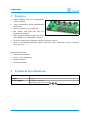
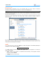
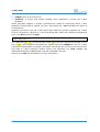
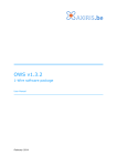
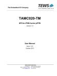
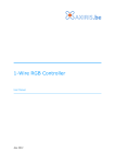
1-Wire Host
User Manual
July 2015
1-Wire Host
Table of Contents
1
Features
3
2
Technical Specifications
3
3
1-Wire Host
Board Overview
On-board Power Supplies (mark 12, 13, 14)
1-Wire RJ45 Connectors (OWn) and Jumpers
Power Output for Single Board Computer (K2, K3)
Power Outputs Connector (K4)
I2C Bus Extension Connectors (K7, K8)
General-purpose I/O Lines (K5)
Connector for I2C Master (K6)
4
4
5
5
6
6
6
7
7
4
I2C Bus
Slave Addresses
Bus Speed
1-Wire Controllers
I/O Expander
8
8
8
8
8
5
Software
1-Wire Host GPIO
1-Wire Automation Software
BeagleBone Black
Raspberry Pi
owfs
9
9
9
9
10
10
6
Legal Information
Disclaimer
Trademarks
12
12
12
7
Contact Information
12
Revision History
Date
Authors
Description
2015-03-28 Peter S'heeren
Initial release.
2015-07-09 Peter S'heeren
Added section about 1-Wire Host GPIO program.
Second release.
2
User Manual
1-Wire Host
1 Features
▪
1-Wire adapter with four independent
1-Wire masters.
▪
1-Wire connections using standardized
RJ45 jacks.
▪
I2C bus interface, up to 400 kHz.
▪
I2C master and local I2C bus are
galvanically isolated.
▪
Eight general-purpose digital I/O lines
are available on a dedicated connector.
▪
Three on-board power supplies including a power injector.
▪
Area for I2C-based extension board (real-time clock, additional 1-Wire controller,
extra I/O lines, …).
Applications include:
▪
Industrial automation.
▪
Server room monitoring.
▪
Weather station.
▪
Home automation.
2 Technical Specifications
Dimensions
158 mm x 83 mm x 20 mm (W x D x H)
Weight
102 g
Power Supply
24 VDC, 1.8 A min.
Connector type 5.5 x 2.5
User Manual
3
1-Wire Host
3 1-Wire Host
Board Overview
2 3
4
5
6
7
8
1
9
15
14
13
12
11 10
Mark
Label
1
K8
I2C bus connector
2
K1
Power supply input connector, type 5.5 x 2.5
4
Description
3
OW4, SJ4 DS2482-100 1-Wire controller D connector, jumper settings
4
OW3, SJ3 DS2482-100 1-Wire controller C connector, jumper settings
5
OW2, SJ2 DS2482-100 1-Wire controller B connector, jumper settings
6
OW1, SJ1 DS2482-100 1-Wire controller A connector, jumper settings
7
K4
Power outputs connector
8
K5
General-purpose I/O lines male connector
9
K7
Extension board connector and mounting area
10
K3
Power output for single board computer
11
K2
Power output for single board computer (same as K3)
12
-
On-board power supply #1
13
-
On-board power supply #2
14
-
On-board power supply #3
15
K6
Connector for I2C master
User Manual
1-Wire Host
On-board Power Supplies (mark 12, 13, 14)
The 1-Wire Host embeds three on-board power supplies:
▪
#1: 8 – 20 V, 1 A, routed to the 1-Wire RJ45 connectors.
▪
#2: 5 V, 1 A, routed to the RJ45 1-Wire connectors.
▪
#3: 5 V, 2 A, provided for power a single board computer.
Adjust potentiometer P1 to control the output voltage of power supply #1.
1-Wire RJ45 Connectors (OWn) and Jumpers
Mark
Description
1
Selectable GND
2
Selectable +5 V power
3
Selectable GND
4
1-Wire DQ (data)
5
1-Wire ground
6
N.C.
7
Selectable 8-20 V power
8
Selectable GND
1 2 3 4 5 6 7 8
1 2 3 4 5 6 7 8
Plug
top view
Receptacle
front view
Each RJ45 connector exposes a 1-Wire channel to the outside world. Each 1-Wire channel
has a dedicated 1-Wire controller, hence all channels operate independently and
concurrently.
Mark
Description
EVn
8-20 V power to pin 7
5Vn
5 V power to pin 2
G8n
Route ground to pin 8
G3n
Route ground to pin 3
G1n
Route ground to pin 1
EVn
5Vn
G8n
G3n
G1n
A set of jumpers select the signals being routed to pins 1, 2, 3, 7 and 8. A closed jumper
routes the signal, an opened jumper doesn't.
Jumper EVn routes the output of on-board power supply #1 to the connector. Jumper
5Vn routes the output of on-board power supply #2 to the connector.
User Manual
5
1-Wire Host
Power Output for Single Board Computer (K2, K3)
Mark
Description
GND
Ground
+5V
+5 V output
K3
GND +5V
K2 and K3 provide power generated by power supply #3. Their main function is to
provide power to the single board computer that controls the 1-Wire Host.
Power Outputs Connector (K4)
Mark
Description
1
5 V (power supply #1)
2
Ground
3
8-20 V (power supply #2)
4
Ground
4
3
2
1
K4
K4 allows one to directly draw power from power supply #1 and #2.
Ground pins 2 and 4 are interconnected.
I2C Bus Extension Connectors (K7, K8)
Mark
Description
+5V
5 V output
GND
Ground
SDA
I2C serial data
SCL
I2C serial clock
K7
K8
These connectors are points for adding I2C devices to the 1-Wire Host.
6
User Manual
1-Wire Host
General-purpose I/O Lines (K5)
Mark
Description
1
GPIO line P0
2
GPIO line P1
3
GPIO line P2
4
GPIO line P3
5
GPIO line P4
6
GPIO line P5
7
GPIO line P6
8
GPIO line P7
9
Ground
10
9 7 5 3 1
K5
10 8 6 4 2
5 V output
This box header brings out the general-purpose digital I/O lines of the PCA9534.
Connector for I2C Master (K6)
Mark
Description
1
Vcc input
2
N.C.
3
I2C serial data (SDA)
4
N.C.
5
I2C serial clock (SCL)
6
Ground
7
N.C.
8
N.C.
9
N.C.
10
N.C.
9 7 5 3 1
K6
10 8 6 4 2
K6 is the connection point for the I2C master that controls the 1-Wire Host. The I2C
master can operate at 3.3 V or 5 V; the board performs level conversions between the
master voltage and the 5 V on the local I2C bus.
The I2C master and the local I2C bus are galvanically isolated. Note that in case the
controlling SBC is powered by the 1-Wire Host, the I2C master and the local I2C bus will
share the same ground thereby nullifying the galvanic isolation.
User Manual
7
1-Wire Host
4 I2C Bus
Slave Addresses
The local I2C bus operates at 5 V level. The bus interconnects a set of on-board I2C
devices. The slave addresses are:
Address
Slave Device
0011000b 1-Wire controller A, DS2482-100, 1 channel
0011001b 1-Wire controller B, DS2482-100, 1 channel
0011010b 1-Wire controller C, DS2482-100, 1 channel
0011011b 1-Wire controller D, DS2482-100, 1 channel
0100000b 8-bit I/O expander, PCA9534
Additional I2C slave devices are possible:
▪
Connector K7 provides a mount point for an extension board.
▪
K8 provides an access point to the I2C bus.
Bus Speed
The 1-Wire Host supports a maximum bus speed of 400 kHz.
1-Wire Controllers
The four 1-Wire controllers allow software to communicate with four 1-Wire slaves
concurrently.
I/O Expander
The I/O expander chip adds 8 general-purpose digital I/O pins to the 1-Wire Host.
8
User Manual
1-Wire Host
5 Software
1-Wire Host GPIO
This program provides command line parameters for controlling the PCA9534 chip. It
runs on Linux.
You can download the program from the Axiris website. A comprehensive read-me is
included.
1-Wire Automation Software
The 1-Wire Automation Software supports the 1-Wire Host. Client command Adapter
Add is central in adding the adapter to the server.
BeagleBone Black
With a BeagleBone Black acting as the controlling SBC, the 1-Wire Host connects to I2C
bus /dev/i2c-1. The adapter is added as follows:
adapter "owhost" add i2cdev "/dev/i2c-1" ds2482 18h ds2482 19h ds2482 1Ah
ds2482 1Bh
This picture shows the device path of each 1-Wire controller on the 1-Wire Host.
User Manual
9
1-Wire Host
Raspberry Pi
If you're using a Raspberry Pi as the controlling SBC, the server offers a detection
procedure for figuring out the interface to use on your Raspberry Pi:
adapter "owhost" add bscdetect ds2482 18h ds2482 19h ds2482 1Ah ds2482 1Bh
The actual interface depends on the revision of the Raspberry Pi and whether or not the
i2c-dev driver is loaded.
If no i2c-dev driver is present, the server uses direct I/O to communicate with the 1-Wire
controller on the 1-Wire Host. The device path of each controller contains a BSC0 or
BSC1 element:
It's recommended to activate the i2c-dev driver. In doing so, software other than the 1Wire server is able to safely access the on-board I/O expander and I2C slaves to are
connected to the extension connectors.
owfs
The 1-Wire Host can be used with owfs, the 1-Wire File System. This software package is
available from the following website:
http://www.owfs.org/
The owfs software includes programs that expose the 1-Wire hardware in a variety of
ways to the system:
▪
owfs: Creates a file system in a specified mount directory. This program requires
software package libfuse.
▪
owhttpd: Sets up a web server.
10
User Manual
1-Wire Host
▪
owftpd: Sets up an FTP server.
▪
owserver: A server that allows multiple client programs to access the 1-Wire
hardware.
These programs support a uniform command line syntax for specifying which 1-Wire
adapters to detect and to expose. For the 1-Wire Host, the --i2c command line option is
of importance.
Suppose you want to set up a web server that listens to port 80. Suppose the 1-Wire
Host is connected to /dev/i2c-1 of the controlling SBC. Enter the following command as
root in the bin directory of owfs:
# ./owhttpd -p 80 --i2c=/dev/i2c-1:0 --i2c=/dev/i2c-1:1 --i2c=/dev/i2c-1:2
--i2c=/dev/i2c-1:3
The /dev/i2c-<n>:<i> syntax denotes offset <n> from I2C address 0011000b on I2C
bus of <i>. The mentioned command line syntax thus tells owhttpd to look for 1-Wire
controllers at addresses 0011000b, 0011001b, 0011010b and 0011011b on the I2C bus.
The type of 1-Wire controller doesn't need to be specified; the owfs software will
distinguish between a DS2482-800 chip and a DS2482-100 chip.
Refer to the owfs documentation for more information.
User Manual
11
1-Wire Host
6 Legal Information
Disclaimer
Axiris products are not designed, authorized or warranted to be suitable for use in space,
nautical, space, military, medical, life-critical or safety-critical devices or equipment.
Axiris products are not designed, authorized or warranted to be suitable for use in
applications where failure or malfunction of an Axiris product can result in personal
injury, death, property damage or environmental damage.
Axiris accepts no liability for inclusion or use of Axiris products in such applications and
such inclusion or use is at the customer's own risk. Should the customer use Axiris
products for such application, the customer shall indemnify and hold Axiris harmless
against all claims and damages.
Trademarks
“Maxim Integrated” is a trademark of Maxim Integrated Products, Inc.
“1-Wire” and “iButton” are registered trademarks of Maxim Integrated Products, Inc.
“Raspberry Pi” is a trademark of the Raspberry Pi Foundation.
All product names, brands, and trademarks mentioned in this document are the property
of their respective owners.
7 Contact Information
Official website: http://www.axiris.eu/
12
User Manual