1
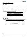
The Embedded I/O Company TAMC002-TM MTCA.4 Rear-I/O µRTM for TAMC220 Version 1.0 User Manual Issue 1.0.1 June 2013 TEWS TECHNOLOGIES GmbH Am Bahnhof 7 25469 Halstenbek, Germany Phone: +49 (0) 4101 4058 0 Fax: +49 (0) 4101 4058 19 e-mail: [email protected] www.tews.com TAMC002-TM-10R MTCA.4 Rear I/O µRTM for TAMC220, Mid-Size front panel TAMC002-TM-11R MTCA.4 Rear I/O µRTM for TAMC220, Full-Size front panel This document contains information, which is proprietary to TEWS TECHNOLOGIES GmbH. Any reproduction without written permission is forbidden. TEWS TECHNOLOGIES GmbH has made any effort to ensure that this manual is accurate and complete. However TEWS TECHNOLOGIES GmbH reserves the right to change the product described in this document at any time without notice. TEWS TECHNOLOGIES GmbH is not liable for any damage arising out of the application or use of the device described herein. Style Conventions Hexadecimal characters are specified with prefix 0x, i.e. 0x029E (that means hexadecimal value 029E). For signals on hardware products, an ‚Active Low’ is represented by the signal name with # following, i.e. IP_RESET#. Access terms are described as: W Write Only R Read Only R/W Read/Write R/C Read/Clear R/S Read/Set 2013 by TEWS TECHNOLOGIES GmbH All trademarks mentioned are property of their respective owners. TAMC002-TM User Manual Issue 1.0.1 Page 2 of 25 Issue Description 1.0.0 Initial Issue 1.0.1 (1) Technical Specification Table: Deleted Module Current Requirements Record mentioning Date November 2011 June 2013 (2) Zone 3 Interface Compatibility Record: Changed the format of the table to match other TEWS products TAMC002-TM User Manual Issue 1.0.1 Page 3 of 25 Table of Contents 1 2 3 PRODUCT DESCRIPTION ........................................................................................... 6 TECHNICAL SPECIFICATION ..................................................................................... 7 HANDLING AND OPERATING INSTRUCTIONS ......................................................... 8 3.1 3.2 3.3 4 ESD Protection ................................................................................................................................ 8 Thermal Considerations ................................................................................................................. 8 Voltage Limits on IndustryPacks .................................................................................................. 8 IPMI SUPPORT ............................................................................................................. 9 4.1 Temperature and Voltage Sensors................................................................................................ 9 4.2 FRU Information .............................................................................................................................. 9 4.2.1 Board Info Area ....................................................................................................................... 10 4.2.2 Product Info Area .................................................................................................................... 10 4.2.3 Multi Record Area ................................................................................................................... 10 4.2.3.1 Zone 3 Interface Compatibility Record .............................................................................. 10 5 FUNCTIONAL DESCRIPTION .................................................................................... 11 5.1 JTAG ............................................................................................................................................... 11 5.2 TCLKA and TCLKB ....................................................................................................................... 11 5.3 I2C Bus ........................................................................................................................................... 11 5.3.1 EEPROM ................................................................................................................................ 12 5.3.2 Temperature Sensor ............................................................................................................... 12 5.3.3 I2C I/O Extender ..................................................................................................................... 13 6 INSTALLATION .......................................................................................................... 14 6.1 IP Modules on the TAMC220 ........................................................................................................ 14 6.1.1 IP I/O Interface ........................................................................................................................ 14 6.2 µRTM Installation .......................................................................................................................... 15 6.2.1 Insertion .................................................................................................................................. 15 6.2.2 Extraction ................................................................................................................................ 15 6.3 Flat Cable Connector Placement ................................................................................................. 16 6.4 Zone 3 Keying................................................................................................................................ 17 7 INDICATORS .............................................................................................................. 18 7.1 LED Indicators ............................................................................................................................... 18 7.1.1 Front Panel LEDs.................................................................................................................... 18 8 I/O CONNECTORS ..................................................................................................... 19 8.1 Overview ........................................................................................................................................ 19 8.2 Board Connectors ......................................................................................................................... 20 8.2.1 IP x I/O Front Panel Connectors (x = A, B, C) ........................................................................ 20 8.2.2 IP x I/O Flat Cable Connectors (x = A, B, C) .......................................................................... 21 8.2.3 Power Good Jumper ............................................................................................................... 22 8.2.4 µRTM_PWR Header ............................................................................................................... 22 8.2.5 TCLKA/TCLKB + PGOOD_EXT Header ................................................................................ 23 8.2.6 RP30 ....................................................................................................................................... 24 8.2.7 RP31 ....................................................................................................................................... 25 TAMC002-TM User Manual Issue 1.0.1 Page 4 of 25 List of Figures FIGURE 1-1 : BLOCK DIAGRAM ...................................................................................................................... 6 FIGURE 5-1 : I2C BUS .................................................................................................................................... 12 FIGURE 6-1 : HOT-SWAP STATES ............................................................................................................... 15 FIGURE 6-2 : FLAT CABLE CONNECTOR PLACEMENT............................................................................. 16 FIGURE 7-1 : FRONT PANEL LED VIEW ...................................................................................................... 18 List of Tables TABLE 2-1 : TECHNICAL SPECIFICATION ..................................................................................................... 7 TABLE 4-1 : TEMPERATURE AND VOLTAGE SENSORS .............................................................................. 9 TABLE 4-2 : FRU INFORMATION .................................................................................................................... 9 TABLE 4-3 : BOARD INFO AREA ................................................................................................................... 10 TABLE 4-4 : PRODUCT INFO AREA .............................................................................................................. 10 TABLE 4-5 : µRTM FRU ZONE 3 INTERFACE COMPATIBILITY RECORD .................................................10 TABLE 5-1 : TCLKX AND DIRECTION SIGNALS .......................................................................................... 11 TABLE 5-2 : µRTM I2C DEVICES.................................................................................................................. 11 TABLE 5-3 : µRTM I2C I/O EXTENDER PORT ASSIGNMENT ..................................................................... 13 TABLE 7-1 : FRONT PANEL LED (CONTROLLED BY THE MMC OF THE FRONT-AMC) ..........................18 TABLE 8-1 : IP I/O CONNECTORS (FRONT PANEL) ................................................................................... 20 TABLE 8-2 : X1, X2, X3 I/O CONNECTORS (ONBOARD FLAT CABLE CONNECTORS) ...........................21 TABLE 8-3 : POWER GOOD SIGNAL JUMPER ............................................................................................ 22 TABLE 8-4 : µRTM_PWR HEADER................................................................................................................ 22 TABLE 8-5 : TCLKA/TCLKB + PGOOD_EXT HEADER ................................................................................. 23 TABLE 8-6 : RP30 PIN ASSIGNMENT ........................................................................................................... 24 TABLE 8-7 : RP31 PIN ASSIGNMENT ........................................................................................................... 25 ! TAMC002-TM User Manual Issue 1.0.1 Page 5 of 25 1 Product Description The TAMC002-TM is a standard Mid-Size/Full-Size MTCA.4 compliant Micro Rear Transition Module compatible to the TAMC220. Two AirmaxVS™ connectors provide access to all IP I/O lines of the TAMC220. The I/O lines are routed to three VHD68 SCSI-V 68-pin connectors in the front panel and also to three 50-pin flat cable connectors that may be used for rack internal wiring or laboratory use. 3 x 68 pin VHDCI Connector 50 I/Os 50 I/Os AirMax Connectors 50 I/Os According to MTCA.4, the TAMC002-TM provides an I2C EEPROM and an I2C temperature sensor. An I2C I/O extender device is used to provide various management signals on the µRTM, with the management being handled by the MMC of the TAMC220. Figure 1-1 : Block Diagram TAMC002-TM User Manual Issue 1.0.1 Page 6 of 25 2 Technical Specification Module Interface Mechanical Interface MTCA.4 Micro Rear Transition Module conforming to MTCA.4 Module Type: Double Mid-Size Module (-10R) Module Type: Double Full-Size Module (-11R) IPMI Support IPMI Version 1.5 Blue Hot-Swap LED Front Panel LEDs Red Failure Indication LED (LED1) (TAMC220 MMC controlled) Green Board OK LED (LED2) Main On-Board Devices I2C I/O Extender PCA9534 (Texas Instruments) I2C EEPROM M24C32 (ST Microelectronics) I2C Temperature Sensor LM75 (National Semiconductor) I/O Interface Front panel I/O 3 x VHD68 SCSI-V connector, one for each IP slot on the TAMC220 Onboard I/O 3 x 50-pin flat cable connectors, on for each IP slot on the TAMC220 Physical Data Management Power: 15mA typical @ +3.3V DC Power Requirements Payload Power: 0A @ +12V DC Operating -40°C to +85°C Storage -40°C to +85°C Temperature Range 448000h MTBF MTBF values shown are based on calculation according to MIL-HDBK-217F and MIL-HDBK-217F Notice 2; Environment: GB 20°C. The MTBF calculation is based on component FIT rates provided by the component suppliers. If FIT rates are not available, MIL-HDBK-217F and MIL-HDBK-217F Notice 2 formulas are used for FIT rate calculation. Humidity 5 – 95 % non-condensing Weight 200g Table 2-1 : Technical Specification TAMC002-TM User Manual Issue 1.0.1 Page 7 of 25 3 Handling and Operating Instructions 3.1 ESD Protection The µRTM is sensitive to static electricity. Packing, unpacking and all other module handling has to be done in an ESD/EOS protected Area. 3.2 Thermal Considerations Forced air cooling is recommended during operation. Without forced air cooling, damage to the device can occur. 3.3 Voltage Limits on IndustryPacks The AMC.0 specification limits the voltages on AMC modules. These limits also apply to mounted IndustryPack Modules and their I/O lines. Refer to the chapter “Voltage Limits on IndustryPack Modules” for details. TAMC002-TM User Manual Issue 1.0.1 Page 8 of 25 4 IPMI Support The Front-AMC module provides a Module Management Controller (MMC) that performs health monitoring, hot-swap functionality and stores the Field Replaceable Unit (FRU) information. The MMC communicates via an Intelligent Platform Management Interface (IPMI) with superordinated IPMI controllers. The TAMC002-TM is controlled by the Front-AMCs MMC. It provides a temperature sensor, FRU information and management signals for hot swap handle status and LED control. 4.1 Temperature and Voltage Sensors The MMC on the TAMC220 monitors sensors onboard the TAMC002-TM and signals sensor events to the superordinated IPMI controller / shelf manager. Available sensors are listed in the table below. Sensor Number Signal Type Thresholds Signal Monitored 0 Event - Hot-swap switch 1 Temperature lnr lcr lnc unc ucr unr LM75 Table 4-1 : Temperature and Voltage Sensors unr: upper non-recoverable, ucr: upper critical, unc: upper non-critical lnr: lower non-recoverable, lcr: lower critical, lnc: lower non-critical 4.2 FRU Information The TAMC002-TM stores the module FRU information in a non-volatile EEPROM. The actual FRU information data is shown below. Area Size (in Bytes) Writeable Common Header 8 no Internal Use Area 0 no Chassis Info Area 0 no Board Info Area variable no Product Info Area variable no Multi Record Area Zone 3 Interface Compatibility Record variable yes Table 4-2 : FRU Information TAMC002-TM User Manual Issue 1.0.1 Page 9 of 25 4.2.1 Board Info Area Product Information Value Version 1 Language Code 0x00 - English Manufacturer date/time determined at manufacturing Board manufacturer TEWS TECHNOLOGIES GmbH Board product name TAMC002-TM Board serial number determined at manufacturing (see board label) Board part number TAMC002-TM-xxR (xx = 10 / 11) Table 4-3 : Board Info Area 4.2.2 Product Info Area Product Information Value Version 1 Language Code 0x00 - English Product manufacturer TEWS TECHNOLOGIES GmbH Product name TAMC002-TM Board part/model number TAMC002-TM-xxR Product version V1.0 Rev.A (see board label) Product serial number determined at manufacturing (see board label) Asset tag = Product serial Number (xx = 10 / 11) Table 4-4 : Product Info Area 4.2.3 Multi Record Area 4.2.3.1 Zone 3 Interface Compatibility Record Parameter Setting Type of Interface Identifier 0x3 OEM Interface Identifier Interface Identifier Body Manufacturer ID (IANA) 0x0071E3 TEWS Technologies Private Enterprise Number OEM defined Interface Designator 0x8DC00000 (0x8 = TAMC, 0xDC = 220) Table 4-5 : µRTM FRU Zone 3 Interface Compatibility Record If the Zone 3 Interface Compatibility record matches the Zone 3 Interface Compatibility record in the TAMC220, the TAMC220 considers the µRTM to be compatible. Otherwise, the TAMC220 considers the µRTM to be incompatible. The Zone 3 Interface Compatibility records are considered as matching if the records are the same length and are identical from offset 9 to the end of the record. Otherwise the record is considered as not matching. TAMC002-TM User Manual Issue 1.0.1 Page 10 of 25 5 Functional Description 5.1 JTAG The TAMC002-TM has no JTAG capable devices onboard; it just connects TDI with TDO, so that it does not break the TAMC220 JTAG chain. TCK and TMS are left unconnected. 5.2 TCLKA and TCLKB TCLKA and TCLKB are routed to a 10-pin flat cable header on the TAMC002-TM. On the TAMC220, these two signals are converted from bidirectional M-LVDS signals to single-ended signals, each with a corresponding direction signal. The signal standard for all four single-ended signals on the µRTM is LVTTL. The direction signals have to be driven by the TAMC002-TM test setup. The user has to make sure that these signals have a valid level if the TCLKx signals are used. TCLKx_DIR Signal Level TCLKx Direction from µRTM point of view 0 Input to TAMC002-TM 1 Output of TAMC002-TM Table 5-1 : TCLKx and direction signals For the pin assignment of these signals, please see the chapter “I/O Connectors”. 5.3 I2C Bus The TAMC002-TM implements the following I2C devices / addresses on the µRTM I2C management bus: Device Type Device EEPROM Temperature Sensor 8-Bit I2C I/O Port I2C Address AT24C32 50h 1010000b LM75 48h 1001000b PCA9534 20h 0100000b Table 5-2 : µRTM I2C Devices TAMC002-TM User Manual Issue 1.0.1 Page 11 of 25 The following figure shows the I2C bus on the TAMC002-TM: J30 Zone 3 Interface PCA9534 0100000 uRTM_MP uRTM_PWR uRTM_TDI uRTM_TDO uRTM_PS# M24C32 1010000 LM75 1001000 I2C EEPROM I2C Temp Port 0 Port 1 Port 2 Port 3 Port 4 Port 5 Port 6 Port 7 HS_SWITCH BLUE_LED LED 1 LED 2 EEPROM_WC# PGOOD I2C GPIO uRTM_I2C Bus Figure 5-1 : I2C Bus 5.3.1 EEPROM The EEPROM contains the FRU information for the µRTM module as described in chapter “IPMI Support”. The EEPROM I2C address is 50h (1010000b). 5.3.2 Temperature Sensor The Temperature Sensor I2C address is 48h (1001000b). TAMC002-TM User Manual Issue 1.0.1 Page 12 of 25 5.3.3 I2C I/O Extender The µRTM provides an 8-Bit I2C I/O Extender device on the I2C management bus that is used for controlling certain management signals on the µRTM. The device I2C address is 20h (0100000b). The TAMC002-TM implements the following pin/signal assignment for the µRTM I2C I/O Extender device: I/O Port Bit I/O Direction 7 I Payload Power Supply Status 0 = Payload Power Supply status is not Good 1 = Payload Power Supply status is Good 6 - - 5 - - O EEPROM Write Protect Control 0 = EEPROM write protection not active 1 = EEPROM write protection active 3 O LED2 (Green) Control 0 = LED off 1 = LED on 2 O LED1 (Red) Control 0 = LED off 1 = LED on 1 O Hot Swap LED (Blue) Control 0 = LED off 1 = LED on 0 I Handle Status 0 = Handle/Switch closed 1 = Handle/Switch open 4 Description Table 5-3 : µRTM I2C I/O Extender Port Assignment TAMC002-TM User Manual Issue 1.0.1 Page 13 of 25 6 Installation This chapter contains general notes regarding installing the µRTM into a system. 6.1 IP Modules on the TAMC220 6.1.1 IP I/O Interface All pins of the IP slot I/O connectors are routed from the AirmaxVS™ connectors to both the flat cable connectors and the VHD68 SCSI-V connectors in the front panel. The maximum current rating if the VHD68 SCSI-V connectors are used is 0.3A per pin. The maximum current rating if the 50-pin flat cable connectors are used is 0.5A per pin. Please note, that the maximum current rating of the VHD68 SCSI-V connectors is 0.3A! TAMC002-TM User Manual Issue 1.0.1 Page 14 of 25 6.2 µRTM Installation During insertion and extraction, the operational state of the µRTM is visible via the blue LED in the µRTM front panel. The following table lists all valid combinations of Hot-swap handle position and blue LED status, including a short description of what’s going on. Blue LED On Off Long Blink Short Blink Open (Pulled out) Extraction: Module can be extracted Insertion: Module is waiting for closed Handle Module is waiting for hot swap negotiation - Hot swap negotiation in progress (Extraction) Closed (Pushed all way in) Module is waiting for hot swap negotiation Module is active (operating) Hot swap negotiation in progress (Insertion) - Handle Figure 6-1 : Hot-Swap states 6.2.1 Insertion Typical insertion sequence: 1. Insert the µRTM into its slot, with the board edges aligned to the card guides 2. Fasten the screws of the front plate, so the module cannot be pushed out by the Front-AMC if it is inserted afterwards 3. Make sure that the module handle is pushed into the inserted position a. Blue LED turns “ON.” (Module is ready to attempt activation by the system) b. Blue LED starts “Long Blink” (Hot Swap Negotiation / Module activation in progress) c. Blue LED turns “OFF”, and green LED turns “ON” (Module is ready and powered) When the Blue LED does not go off but returns to the “ON” state, the µRTM FRU information is incompatible to the Front-AMC. 6.2.2 Extraction Typical Extraction sequence: 1. Pull the module handle out ½ way a. Blue LED starts “Short Blink” (Hot Swap Negotiation in progress) b. Blue LED turns “ON” (Module is ready to be extracted) 2. Loosen the screws of the front plate 3. Pull the module handle out completely and extract the µRTM from the slot. TAMC002-TM User Manual Issue 1.0.1 Page 15 of 25 6.3 Flat Cable Connector Placement All flat cable connectors onboard the TAMC002-TM are aligned in a 2.54mm grid. This allows for easy test setup creation using hole matrix boards. Screw holes for fastening the test setup with the TAMC002-TM are present in the 2.54mm grid as well. All actual dimensions are presented in the following figure. The pins with number 1 are marked red: 91,44 mm 81,32 mm 55,92 mm 38,14 mm 30,52 mm 10,20 mm 8,80 mm P3 15,24 mm P5 2,54 mm 35,56 mm 37,46 mm X3 J1 P4 71,12 mm X1 X2 P1 RP30 A1 AirMax Connectors 132,15 mm P2 X1 RP31 A1 76,18 mm Figure 6-2 : Flat Cable Connector Placement TAMC002-TM User Manual Issue 1.0.1 Page 16 of 25 6.4 Zone 3 Keying The TAMC002-TM provides the following male keying pin: N A Rotation 5 180 View View into the rear of the Front-AMC white = clearance TAMC002-TM User Manual Issue 1.0.1 Voltage Levels Dependent on IP Modules, but >±10V Page 17 of 25 7 Indicators 7.1 LED Indicators 7.1.1 Front Panel LEDs For a quick visual inspection, the TAMC002-TM provides the following front panel LEDs: Full-Size FAIL OK C B A Mid-Size TAMC002-TM Figure 7-1 : Front Panel LED View LED Color State Off HS Blue FAIL Red OK Green Description No Power or µRTM is ready for normal operation Short Blink Hot-Swap negotiation (extraction) Long Blink Hot-Swap negotiation (insertion) On µRTM is ready to attempt activation by the system or µRTM is ready to be extracted Off No fault On Failure or out of service status Off µRTM is not powered up On µRTM is powered and OK Table 7-1 : Front Panel LED (controlled by the MMC of the Front-AMC) TAMC002-TM User Manual Issue 1.0.1 Page 18 of 25 8 I/O Connectors 8.1 Overview P3 P5 X3 J1 P4 P2 X1 X2 RP30 A1 AirMax Connectors P1 X1 RP31 A1 Figure 11-1: Board Connectors and Headers ID Description RP30 MTCA.4 Rear-I/O and Management Signals Connector RP31 MTCA.4 Rear-I/O Connector P4 µRTM_PWR Header P5 TCLKA / TCLKB + PGOOD_EXT Header J1 Power Good Signal Jumper P1 IP Slot A I/O Flat Cable Connector X1 IP Slot A I/O VHD68 Front Panel Connector P2 IP Slot B I/O Flat Cable Connector X2 IP Slot B I/O VHD68 Front Panel Connector P3 IP Slot C I/O Flat Cable Connector X3 IP Slot C I/O VHD68 Front Panel Connector Table 11-1: Board Connectors and Headers TAMC002-TM User Manual Issue 1.0.1 Page 19 of 25 8.2 Board Connectors 8.2.1 IP x I/O Front Panel Connectors (x = A, B, C) Pin-Count 68 Connector Type VHDCI Female 68pos. 0.8mm spacing Source & Order Info HDRA-EC68LFDT-SL+ (Honda) Location Front plate Pin Assignment Pin Description Note Pin Description Note 1 IO_x_01 0.3A max 26 IO_x_26 0.3A max 2 IO_x_02 0.3A max 27 IO_x_27 0.3A max 3 IO_x_03 0.3A max 28 IO_x_28 0.3A max 4 IO_x_04 0.3A max 29 IO_x_29 0.3A max 5 IO_x_05 0.3A max 30 IO_x_30 0.3A max 6 IO_x_06 0.3A max 31 IO_x_31 0.3A max 7 IO_x_07 0.3A max 32 IO_x_32 0.3A max 8 IO_x_08 0.3A max 33 IO_x_33 0.3A max 9 IO_x_09 0.3A max 34 IO_x_34 0.3A max 10 IO_x_10 0.3A max 35 IO_x_35 0.3A max 11 IO_x_11 0.3A max 36 IO_x_36 0.3A max 12 IO_x_12 0.3A max 37 IO_x_37 0.3A max 13 IO_x_13 0.3A max 38 IO_x_38 0.3A max 14 IO_x_14 0.3A max 39 IO_x_39 0.3A max 15 IO_x_15 0.3A max 40 IO_x_40 0.3A max 16 IO_x_16 0.3A max 41 IO_x_41 0.3A max 17 IO_x_17 0.3A max 42 IO_x_42 0.3A max 18 IO_x_18 0.3A max 43 IO_x_43 0.3A max 19 IO_x_19 0.3A max 44 IO_x_44 0.3A max 20 IO_x_20 0.3A max 45 IO_x_45 0.3A max 21 IO_x_21 0.3A max 46 IO_x_46 0.3A max 22 IO_x_22 0.3A max 47 IO_x_47 0.3A max 23 IO_x_23 0.3A max 48 IO_x_48 0.3A max 24 IO_x_24 0.3A max 49 IO_x_49 0.3A max 25 IO_x_25 0.3A max 50 IO_x_50 0.3A max 51 – 68 NC Table 8-1 : IP I/O Connectors (Front Panel) TAMC002-TM User Manual Issue 1.0.1 Page 20 of 25 8.2.2 IP x I/O Flat Cable Connectors (x = A, B, C) Pin-Count 50 Connector Type Flat Cable Connector Source & Order Info AMP 104340 Pin Assignment Pin Description Pin Description 1 IO_x_01 26 IO_x_26 2 IO_x_02 27 IO_x_27 3 IO_x_03 28 IO_x_28 4 IO_x_04 29 IO_x_29 5 IO_x_05 30 IO_x_30 6 IO_x_06 31 IO_x_31 7 IO_x_07 32 IO_x_32 8 IO_x_08 33 IO_x_33 9 IO_x_09 34 IO_x_34 10 IO_x_10 35 IO_x_35 11 IO_x_11 36 IO_x_36 12 IO_x_12 37 IO_x_37 13 IO_x_13 38 IO_x_38 14 IO_x_14 39 IO_x_39 15 IO_x_15 40 IO_x_40 16 IO_x_16 41 IO_x_41 17 IO_x_17 42 IO_x_42 18 IO_x_18 43 IO_x_43 19 IO_x_19 44 IO_x_44 20 IO_x_20 45 IO_x_45 21 IO_x_21 46 IO_x_46 22 IO_x_22 47 IO_x_47 23 IO_x_23 48 IO_x_48 24 IO_x_24 49 IO_x_49 25 IO_x_25 50 IO_x_50 Table 8-2 : X1, X2, X3 I/O Connectors (onboard flat cable connectors) TAMC002-TM User Manual Issue 1.0.1 Page 21 of 25 8.2.3 Power Good Jumper The Power Good Jumper is used to select the power good signal source. This can either be the TAMC002-TM internal power good generation, which is essentially a pull-up resistor to µRTM_MP, or an external power good signal. If µRTM_PWR is used to generate external voltages (e.g. on an external test setup), the user has to take care of a correct power good signal. The jumper is labeled in order to find position 1 more easily. Jumper Configuration Description No jumper plugged not allowed Jumper in Pos. 1-2 Internal Power Good Signal Jumper in Pos. 2-3 External Power Good Signal Table 8-3 : Power Good Signal Jumper 8.2.4 µRTM_PWR Header µRTM_PWR and GND are available on a 10-pin header to be used for external test setups. If µRTM_PWR is used to generate external voltages, the user has to take care of a correct power good signal. The external power good signal is located on the TCLKA/TCLKB Header. The flat cable header is labeled onboard to recognize the signals more easily. Pin Signal 1 (square pad) µRTM_PWR 2 GND 3 µRTM_PWR 4 GND 5 µRTM_PWR 6 GND 7 µRTM_PWR 8 GND 9 µRTM_PWR 10 GND Table 8-4 : µRTM_PWR Header TAMC002-TM User Manual Issue 1.0.1 Page 22 of 25 8.2.5 TCLKA/TCLKB + PGOOD_EXT Header TCLKA / TCLKB and their respective DIRECTION signals are available on a 10-pin header to be used for external test setups. The external power good signal is also located on this header. The flat cable header is labeled onboard to recognize the signals more easily. Pin Signal I/O 1 (square pad) GND 2 GND 3 TCLKA I/O 4 TCLKB I/O 5 TCLKA_DIR I/O 6 TCLKB_DIR I/O 7 GND 8 GND 9 GND Description See chapter “Functional Description” for details about signal standard and TTL Level Signal, indicates the status of external power supplies: 10 PGOOD_EXT I 1 = POWER OK 0 = POWER NOT OK Table 8-5 : TCLKA/TCLKB + PGOOD_EXT Header If µRTM_PWR is used to generate external voltages, the user has to take care of a correct power good signal. TAMC002-TM User Manual Issue 1.0.1 Page 23 of 25 8.2.6 RP30 Pin-Count 90 Connector Type FCI AirmaxVS®, Male Source & Order Info FCI 10034249-101LF (without Short-Pin) FCI 10034249-111LF (with Short-Pin) Pin Assignment I H G F E D C B A 1 IO_C_26 IO_C_01 PWR GND PWR IO_C_27 IO_C_28 IO_C_02 IO_C_03 2 IO_C_29 IO_C_30 GND PWR PWR IO_C_04 IO_C_05 IO_C_31 IO_C_32 3 IO_C_06 IO_C_07 PWR GND PWR IO_C_33 IO_C_34 IO_C_08 IO_C_09 4 IO_C_35 IO_C_36 GND PWR PWR IO_C_10 IO_C_11 IO_C_37 IO_C_38 5 IO_C_12 IO_C_13 MP GND SCL IO_C_39 IO_C_40 IO_C_14 IO_C_15 6 IO_C_41 IO_C_42 GND SDA PS# IO_C_16 IO_C_17 IO_C_43 IO_C_44 7 IO_C_18 IO_C_19 TCLKA GND TDO*) IO_C_45 IO_C_46 IO_C_20 IO_C_21 8 IO_C_47 IO_C_48 GND TCLKA_DIR TDI*) IO_C_22 IO_C_23 IO_C_49 IO_C_50 9 IO_C_24 IO_C_25 TCLKB GND TCK*) IO_B_26 IO_B_01 IO_B_27 IO_B_28 10 IO_B_02 IO_B_03 GND TCLKB_DIR TMS*) IO_B_29 IO_B_30 IO_B_04 IO_B_05 Table 8-6 : RP30 Pin Assignment *) = The TAMC002-TM has no JTAG capable devices onboard; it just connects TDI with TDO, so that it does not break the TAMC220 JTAG chain. TCK and TMS are left unconnected. TAMC002-TM User Manual Issue 1.0.1 Page 24 of 25 8.2.7 RP31 Pin-Count 90 Connector Type FCI AirmaxVS®, Male Source & Order Info FCI 10034249-101LF (without Short-Pin) FCI 10034249-111LF (with Short-Pin) I H G F E D C B A 1 IO_B_31 IO_B_32 IO_B_06 IO_B_07 IO_B_33 IO_B_34 IO_B_08 IO_B_09 IO_B_35 2 IO_B_36 IO_B_10 IO_B_11 IO_B_37 IO_B_38 IO_B_12 IO_B_13 IO_B_39 IO_B_40 3 IO_B_14 IO_B_15 IO_B_41 IO_B_42 IO_B_16 IO_B_17 IO_B_43 IO_B_44 IO_B_18 4 IO_B_19 IO_B_45 IO_B_46 IO_B_20 IO_B_21 IO_B_47 IO_B_48 IO_B_22 IO_B_23 5 IO_B_49 IO_B_50 IO_B_24 IO_B_25 IO_A_26 IO_A_01 IO_A_27 IO_A_28 IO_A_02 6 IO_A_03 IO_A_29 IO_A_30 IO_A_04 IO_A_05 IO_A_31 IO_A_32 IO_A_06 IO_A_07 7 IO_A_33 IO_A_34 IO_A_08 IO_A_09 IO_A_35 IO_A_36 IO_A_10 IO_A_11 IO_A_37 8 IO_A_38 IO_A_12 IO_A_13 IO_A_39 IO_A_40 IO_A_14 IO_A_15 IO_A_41 IO_A_42 9 IO_A_16 IO_A_17 IO_A_43 IO_A_44 IO_A_18 IO_A_19 IO_A_45 IO_A_46 IO_A_20 10 IO_A_21 IO_A_47 IO_A_48 IO_A_22 IO_A_23 IO_A_49 IO_A_50 IO_A_24 IO_A_25 Table 8-7 : RP31 Pin Assignment TAMC002-TM User Manual Issue 1.0.1 Page 25 of 25