1
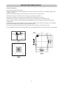
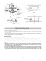
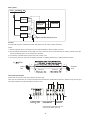
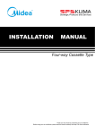
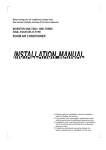
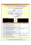
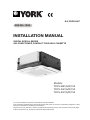
E-II-YDCS-0907
ENGLISH
INSTALLATION MANUAL
DIGITAL SCROLL SERIES
AIR-CONDITIONER COMPACT FOUR-WAY CASSETTE
Models:
YDCS-28C(A/B)15A
YDCS-36C(A/B)15A
YDCS-45C(A/B)15A
For correct installation, read this manual before starting installation.
Only trained and qualified service personnel should install, repair or service air conditioning equipment. Users
should not install the air conditioner by themselves.
All pictures are only sketches. If there is any difference between pictures in this manual and the actual shape
of the air conditioner you purchased, the actual shape shall prevail.
CONTENTS
INSTALLATION INFORMATION .................................................................................
4
INSTALLATION LOCATION .......................................................................................
5
INDOOR UNIT INSTALLATION .................................................................................
6
DRAINPIPE INSTALLATION .....................................................................................
9
ELECTRIC WIRING ................................................................................................... 11
CONTROL ................................................................................................................. 13
NETWORK ADDRESS SETTING .............................................................................. 14
TROUBLE SHOOTING .............................................................................................. 14
TEST OPERATION .................................................................................................... 15
INSTALLATION INFORMATION
• Please read this Installation Manual carefully before installation.
• The Air Conditioner must be installed by qualified service personnel.
• When installing the indoor unit or its tubing, please follow this manual as strictly as possible.
• When all the installation work is finished, please turn on the power only after a thorough check.
• This manual is subject to changes due to technological improvement without further notices.
Note:
• The installer should illustrate how to correctly use and repair the appliance to user and remind the user carefully reading
and keeping both Installation Manual and Owner's Manual after the air conditioner is installed.
• Pictures in this manual are based on standard model. The shape shown may be slightly different from the air conditioner
you purchased.
ACCESSORIES
Please make sure the accessories are complete and keep those accessories carefully.
Wiring
T
Cautions on remote controller installation:
• Do not throw or beat the remote controller.
• Before installation, operate the remote controller to determine its location in a reception range.
• Keep the remote controller at least 1m apart from the nearest TV set or stereo equipment. (It is necessary to prevent
image disturbances or noise interferences.)
• Do not install the remote controller in a place exposed to direct sunlight or close to a heating source, such as a stove.
• Make sure to install the battery in correct direction.
• Please read the Remote controller User's Manual carefully before using.
4
INSTALLATION LOCATION
INDOOR UNIT SHOULD BE INSTALLED AT:
• A place where there is enough room for installation and maintenance.
• The ceiling is structurally sound to hold the Indoor Unit.
• A place that is well ventilated and the influence of weather is the least.
• A place that the airflow can reach every corners of the room.
• A place where the refrigerant connecting pipe and drain pipe can reach out easily.
• A place free of flammable gas or corrosive gas leakage.
• A place where there is no direct affection from man-made high-voltage current and highfrequency wave.
• A place which is far from noises and vibration.
CAUTIONS
Location in the following places may cause malfunction of the machine. (If unavoidable, please consult your local dealer.)
A. There is mineral oil like the oil of cutting machine.
B. There is much salty air. (Near the coast)
C. There is caustic gas such as sulfuric gas. (Near the hotspring.)
D. Factory where the voltage fluctuate greatly.
E. In the car or in the cabin.
F. In the kitchen or a place full of oil steam..
G. There is strong electromagnetic wave.
H. There is combustible gas or materials.
I. There is much evaporating acid or alkaline gas.
J. Other special areas.
NOTES BEFORE INSTALLATION
1. Decide the correct carry-in path.
2. Move this unit as originally packaged as possible.
3. If the air conditioner is installed on a metal part of the building, it must be electrically insulated according to the relevant
electrical code.
4. If installing in a lonely building or at a high position where it is hot and humid with frequent thunderstorm, lightningprotection equipment is necessary.
5
INDOOR UNIT INSTALLATION
1. Install the main body
A. The existing ceiling (to be horizontal)
a. Please cut a quadrangular hole of 600 600mm in the ceiling according to the shape of the installation paper board.
(Refer to Chart3,4)
• The center of the hole should be at the same position of that of the air conditioner body.
• Determine the lengths and outlets of the connecting pipe, drain pipe and cables.
• To balance the ceiling and to avoid vibration, please enforce the ceiling when necessary.
b. Please select the position of installation hooks according to the hook holes on the installation board.
• Drill four holes of Ø12mm, 50~55mm deep at the selected positions on the ceiling. Then embed the expansible
hooks(fittings).
• Face the concave side of the installation hooks toward the expansible hooks. Determine the length of the installation
hooks from the height of ceiling, then cut off the unnecessary part.
• If the ceiling is extremely high, please determine the length of the installation hook according to facts.
• Cut the installation hook open in the middle position, then use appropriate length of reinforcing rod (Ø12) to weld together.
A 280
A
28.5
67
422
Inlet
Outlet
>2300
Outlet
>1000
75
>1000
580(Body)
61
650(Panel)
>1000
>1000
6
650(Panel)
215
580(Body)
Ground
The length could be calculated from Chart5:
Length=210+L (in general, L is half of the whole length of the installation hook)
c. Please adjust the hexangular nuts on the four installation hooks evenly, to ensure the balance of the body.
• Use the transparent hose filled with water to check the lever of the main body from the four sides or diagonal line
direction, the lever indicator also can check the lever from four sides of the main body Refer to chart 6)
• If the drainpipe is awry, leakage will be caused by the malfunction of the water-level switch.
• Adjust the position to ensure the gaps between the body and the four sides of ceiling are even. The body's lower part
should sink into the ceiling for 10~12mm (Refer to chart5).
• Locate the air conditioner firmly by wrenching the nuts after having adjusted the body's position well.
A
Hook
285
Body
Nut
Electric
throttl evice
Panel
Ceiling
600
Electricthrottle
device
Body
34
Body
176
10-12
L
Installation
Installation
16
(Accessory)
Ceiling
Colourless
Horizontal
indicator
B. New built houses and ceilings
a. In the case of new built house, the hook can be embedded in advance (refer to the A.b mentioned above). But it should
be strong enough to bear the indoor unit and will not become loose because of concrete shrinking.
b. After installing the body, please fasten the installation paper board onto the air conditioner with bolts (M5x16) to determine
in advance the sizes and positions of the hole opening on ceiling.
Please first guarantee the flatness and horizontal of ceiling when installing it.
Refer to the A.a mentioned above for others.
c. Refer to the A.c mentioned above for installation.
d. Remove the installation paper board.
7
2. Install The Panel
• Never put the panel face down on floor or against the wall, or on bulgy objects.
• Never crash or strike it.
(1) Remove the inlet grid.
a. Slide two grid switches toward the middle at the same time, and then pull them up. (Refer to chart 9)
b. Draw the grid up to an angle of about 30 , and remove it. (Refer to chart 10)
45º
Grid switch
Chart 9
Chart 10
2. Install The Panel
a. Align the swing motor on the panel to the water receiver of the body properly. (Refer to chart 11)
b. Hang the four fixed rope of the main body to the installation cover and the other three covers of the swing motor: (Refer
to chart 11-1 and 2)
CAUTIONS
The installation cover of the swing motor must sink into the corresponding water receiver.
c. Install the panel on the main body with bolt (M5x16) and washer. (Refer to chart 11-4)
d. Adjust the four panel hook screws to keep the panel horizontal, and screw them up to the ceiling evenly.
e. Regulate the panel in the direction of the arrow in Chart 11-3 slightly to fit the panel's center to the center of the ceiling's
opening. Guarantee that hooks of four corners are fixed well.
f. Keep fastening the screws under the panel hooks, until the thickness of the sponge between the body and the panel's
outlet has been reduced to about 4~6mm. The edge of the panel should contact with the ceiling well. (Refer to chart 12)
• Malfunction described in Chart 13 can be caused by inappropriate tightness the screw.
• If the gap between the panel and ceiling still exists after fastening the screws, the height of the indoor unit should be
modified again. You can modify the height of the indoor unit through the openings on the panel's four corners, if the lift
of the indoor unit and the drainpipe is not influenced (refer to chart 14-right).
(3) Hang the air-in grid to the panel, then connect the lead terminator of the swing motor and that of the control
box with corresponding terminators on the body respectively.
(4) Relocate the air-in grid in the procedure of reversed order, install the air-in grid.
8
Drain side
Electric throttle device
Steel rope
Ceiling
Leakage
Dew
Swing motor installation cover
Chart 13
Cover
Swing motor side
Bolt, washer
Chart 11
Body
Inlet air
Panel sealing foam
Ceiling
Panel foam 2
Hexagonal nut
Horizontal adjustment
Panel foam
Outlet air
Ceiling
Air plate
Panel
Panel foam
Chart 14
Chart 12
DRAIN PIPE INSTALLATION
1. Install the drainpipe of the indoor unit
• You can use a polyethylene tube as the drainpipe (out-dia. 31~32mm, in-dia. 25mm). It could be bought at local market
or from your dealer.
• Set the mouth of the drainpipe onto the root of the body's pump-pipe, and clip the drainpipe and the out-let pipe sheath
(fittings) together firmly with the out-let pipe clasp (fitting).
CAUTIONS
Use your strength carefully to prevent the pump-pipe from breaking.
• The body's pump pipe and the drainpipe (especially the indoor part) should be covered evenly with the out-let pipe
sheath (fittings) and be bound tightly with the constrictor to prevent condensation caused by entered air.
• To prevent water from flowing backwards into the air conditioner while the air conditioner stops, please lean the drainpipe
down toward outdoor (outlet-side) at a degree of over 1/50. And please avoid any bulge or water deposit. (Refer to Chart
15.a)
• Do not drag the drainpipe violently when connecting to prevent the body from being pulled. Meanwhile. one supportpoint should be set every 1~1.5m to prevent the drainpipe from yielding (Refer to Chart15.b). Or you can tie the drainpipe
with the connecting pipe to fix it. (Refer to Chart 15.c)
• In the case of prolonged drainpipe, you had better tighten its indoor part with a protection tube to prevent it from loosing.
• If the outlet of the drainpipe is higher than the body's pump joint, the pipe should be arranged as vertically as possible.
And the lift distance must be less than 200mm, otherwise the water will overflow when the air conditioner stops. (Refer
to Chart 16)
9
The end of the drainpipe should be over 50mm higher than the ground or the bottom of the drainage chute, and do not
immerse it in water. If you discharge the water directly into sewage be sure to make a U-form aquaseal by bending the
pipe up to prevent the smelly gas entering the house through the drain pipe.
CAUTIONS
All the joints of the drain system must be sealed to prevent water leakage.
Lean over 1/50
Lean over 1/50
Pump-pipe clasp
(the fittings)
Constrict here
Lean over 1/50
Drainpipe
Chart 16
Connecting pipe
Chart 15
2. Drainage test
• Check whether the drainpipe is unhindered
• New built house should have this test done before paving the ceiling.
1- Remove the test cover, and stow water of about 1500ml to the water receiver through the stow tube. (Refer to Chart 17)
Body
Drain pipe
Stow
Drain plug
Stow tube
Water receiver
Drip tray
Chart 17
2- Turn on the power, and operate the air conditioner under the "COOLING" mode. Listen to the sound of the drain pump.
Check whether the water is discharged well (a lag of 1min is allowed before discharging, according to the length of
the drain pipe), and check whether water leaks from the joints.
CAUTIONS
If there is any malfunction, please resolve it immediately.
3- Stop the air conditioner for there minutes, check if everything is ok. If the drain hose is located unreasonable, water
overflow will cause the Alarm indicator lamp flashing (For both cooling and heating type or cooling only type), even
the water leak out from the water receiver.
10
MATERIAL AND SIZE OF THE PIPES
Three length (3m,5m,10m) of pipes are available to purchase.
Refrigerant
Size(mm)
R22/R407C
R410A
19.0
16.0
9.53
9.53
ELECTRIC WIRING
CAUTIONS
1. The air conditioner should use separate power supply with rated voltage, the voltage of power supply must be
within90%~110% of rated value.
2. The external power supply to the air conditioner should have ground wiring, which is linked to the ground wiring of the
indoor and outdoor unit.
3. The wiring work should be done by qualified persons according to circuit drawing.
4. A disconnection device having an air gap contact separation in all active conductors should incorporated in the fixed
wiring according to the National wiring regulation.
5. Be sure to locate the power wiring and the signal wiring well to avoid cross-disturbance and their contact with connecting
pipe or stop valve body.
6. The wiring attached to this air conditioner is 6m long. Be sure to prolong it with wiring of the same type and proper
length if necessary. Generally, do not twist two wiring together unless the joint is soldered well and covered with insulator
tape.
7. Do not turn on the power until you have checked carefully after wiring.
8. The yellow and green wire can only be used to link to the ground wiring.
The Specification of Power
MODEL
POWER
28~45
1-PHASE
PHASE
FREQUENCY AND VOLT
CIRCUIT BREAKER/FUSE
INDOOR UNIT POWER WIRING
30/25
(A)
2
(mm )
≥2.5
≥2.5
GROUND WIRING
INDOOR/OUTDOOR
CONNECTING WIRING
POWER WIRING 2.5
2
(mm )
HEAVY-CURRENT SIGNAL 1.5~2.5
CAUTIONS
A disconnection device having an air gap contact separation in all active conductors should be incorporated in the fixed
wiring according to the National Wiring Regulation.
Ground the air conditioner properly to obtain a good anti-interference effect .
11
Wiring Chart
Power 2 20-240V 5 0Hz
INDOOR UNIT
CENTRAL CONTROL
MONITOR(CCM)
COMPUTER
INDOOR UNIT
OUTDOOR UNIT
INDOOR UNIT
the shielded twisted-pair wire
Caution:
The reserved function is indicated in broken line table,users can select it when necessary.
NOTE:
1. Please remember the surroundings (environmental temperature, direct sunlight, rain etc.)
2. We consider the minimal size of the metal core as the wire size. So it is recommended you adopt a thicker one as the
power conducting wire so as to avoid power decrease;
3. Connect the grounded wire to both indoor and outdoor units;
4. This chart is just an on-site wire-connecting example. For details, please refer to relative National criteria.
A
20m
unit
B
A
Indoor
Unit
Outdoor
Unit
Entrance
Entrance
Terminal Board Diagram
Please refer to the indoor unit wiring diagram for the wiring.
Note: The air-conditioners can connect with Central Control Monitor (CCM). Before operation, please wiring correctly and
set system address and network address of indoor units.
X
Y (E)
P Q (E)
TO INDOOR POWER To Central Control Monitor TO OUTDOOR
(CCM)COMM. BUS
COMM. BUS
220-240V 5 0/60Hz
Please adopt the shielded twisted-pair wire,
and connect the shielded layer to (E)
12
CONTROL
Please number the indoor units during the installation . For example, for the first outdoor unit ,the number of the first
indoor unit is 1-1, the second indoor unit is 1-2, and the set address is 1 and 2 respectively , the others is analogical.
POWER_S
16-31
D
BC E
789A
789A
NUM_S
3456
0-15
ENC1
16-31
NUM_S
F 012
3456
D
BC E
F 012
ENC2
NUM_S
16-31
D
BC E
789A
0-15
789A
ENC2
Model 1 show the address '0-F' respectively,
that is, '0-15' indoor unit
3456
0-15
F 012
3456
D
BC E
F 012
ENC2
Model 2 show the address '0-F' respectively,
that is, '16-31' indoor unit
CAUTION
1.The system together have 32units(0-31),everyone has only system addresscode,
If two addresses are the same in one system , the abnormal operation will occur.
2.Please switch off the power before setting,otherwise the unexpected error will occur.
ENC1
Note: The horsepower has
been set before leaving the
factory, anyone can't modify it
except the maintenance
person.
SW1/ENC2
DIAL SWITCH
For set horsepower
Code
Capacity (Horsepower)
0
2200W (0.8HP)
1
2800W (1.0HP)
2
3600W (1.2HP)
3
4500W (1.5HP)
DIAL SWITCH
SETTING ADDRESS
The system together have 32units(0-31),everyone has only system addresscode,
If two addresses are the same in one system , the abnormal operation will occur.
13
NETWORK ADDRESS SETTING
Every air-conditioner in network has only one network address to distinguish each other. Address code of air-conditioner
in LAN is set by code switch on Network Interface Module (NIM), and the set range is 0-63.
Toggle switch set
S1
S2
DE
BC
DE
BC
DE
BC
DE
BC
9A
78
DE
DE
9A
78
DE
DE
BC
9A
BC
48-63
78
78
BC
BC
9A
012
F
~
32~47
3456
3456
2
9A
012
F
1
~
78
9A
2
012
F
3456
3456
1
16~31
78
78
012
F
012
F
~
00~15
3456
3456
2
9A
012
F
1
~
3456
3456
2
012
F
78
012
F
1
Network address code
9A
TROUBLE SHOOTING
Nº
Type
Contents
LED Lamp flash
Remarks
1
Malfunction
The evaporator sensor
check point is abnomal,
or room temp.sensor is
abnormal.
Run lamp flashes
at 2.5Hz.
After the malfunctions
disappear, it restores
automatically.
2
Malfunction
Indoor/outdoor unit
communication is abnormal.
The timer lamp
flashes at 2.5Hz.
After the malfunctions
disappear, it restores
automatically.
3
Malfunction
Condenser sensor check
point is abnormal or outdoor
temp. sensor is abnormal.
All the indoor alarm
lamps flash at 0.5Hz.
After the malfunctions
disappear, it restores
automatically.
4
Malfunction
Water level switch
is abnormal.
Alarm lamp flashes
at 2.5Hz.
If the malfunctions can t be
solved in three min. all the
indoor alarm lamps flash at
0.5Hz. Turn off the power to
restore.
5
Alarm
Mode conflict.
Defrost lamp flashes
at 2.5Hz.
When the indoor unit turns to
heating mode or is turned off,
the alarm will disappear.
14
T
TEST OPERATION
1. The test operation must be carried out after the entire installation has been completed.
2. Please confirm the following points before the test operation:
• The indoor unit and outdoor unit are installed properly.
• Tubing and wiring are correctly completed.
• The refrigerant pipe system is leakage-checked.
• The drainage is unimpeded.
• The heating insulation works well.
• The ground wiring is connected correctly.
• The length of the tubing and the added stow capacity of the refrigerant have been recorded.
• The power voltage fits the rated voltage of the air conditioner.
• There is no obstacle at the outlet and inlet of the outdoor and indoor and indoor units.
• The gas-side and liquid-side stop valves are opened.
• The air conditioner is pre-heated by turning on the power.
3. According to the user s requirement, install the remote controller frame where the remote controller s signal can reach
the indoor unit smoothly.
4. Test operation
Set the air conditioner under the mode of "COOLING" with the remote controller, and check the following points per the
"Owner's Manual" If there is any malfunction, please resolve it through chapter "Trouble shooting".
1) The indoor unit
a. Whether the switch on the remote controller works well.
b. Whether the buttons on the remote controller works well.
c. Whether the air flow louver moves normally.
d. Whether the room temperature is adjusted well.
e. Whether the indicator lights normally.
f. Whether the temporary buttons works well.
g. Whether the drainage is normal.
h. Whether there is vibration or abnormal noise during operation.
I. Whether the air conditioner heats well in the case of the HEATING/COOLING type.
2) The outdoor unit
a. Whether there is vibration or abnormal noise during operation.
b. Whether the generated wind, noise, or condensed water by the air conditioner have influenced your neighborhood.
c. Whether any of the refrigerant is leaked.
CAUTION
Protection function will delay the startup of compressor for 3 minutes in case the unit is turned on immediately after power
on or restarted after shutdown.
15
DE - COMMISSIONING DISMANTLING & DISPOSAL
This product contains refrigerant under pressure, rotating parts, and electrical connections which
may be a danger and cause injury!
All work must only be carried out by competent persons using suitable protective clothing and safety precautions.
Read the Manual
Risk of electric shock
Unit is remotely controlled
and may start without warning
1. Isolate all sources of electrical supply to the unit including any control system supplies switched by the unit. Ensure that all points of electrical and gas
isolation are secured in the OFF position. The supply cables and gas pipework may then be disconnected and removed. For points of connection refer
to unit installation instructions.
2. Remove all refrigerant from each system of the unit into a suitable container using a refrigerant reclaim or recovery unit. This refrigerant may then be
re-used, if appropriate, or returned to the manufacturer for disposal.Under No circumstances should refrigerant be vented to atmosphere. Where
appropriate, drain the refrigerant oil from each system into a suitable container and dispose of according to local laws and regulations governing
disposal of oily wastes.
3. Packaged unit can generally be removed in one piece after disconnection as above. Any fixing down bolts should be removed and then unit lifted from
position using the points provided and equipment of adequate lifting capacity. Reference MUST be made to the unit installation instructions for unit
weight and correct methods of lifting. Note that any residual or spilt refrigerant oil should be mopped up and disposed of as described above.
4. After removal from position the unit parts may be disposed of according to local laws and regulations.
E-II-YDCS-0907
ENGLISH