1
TOYO
INTELLIGENT
INVERTER
Operating Manual
~ Induction Motor Vector Control Mode ~
Induction motor vector mode
Foreword
Thank you for choosing TOYO inverter product. This instruction manual is for TOYO VF66B inverter FULL mode
(Induction motor vector mode). Before using TOYO VF66B inverter in Induction motor vector mode, please read
a set of instruction manuals (Installation, Basic operation, Trouble shooting and Maintenance) to get familiarize
with the feature of TOYO VF66B inverter and use this manual for those functions which are not covered in an
instruction manual (basic operation edition).
TOYO VF66B inverter has many special features in addition to basic function in order to accommodate wide variety
of applications and maximize performance of the system. For the special feature of VF66B, please refer to the
value stated in the dedicated instruction manuals or test data report.
1
Induction motor vector mode
Please read before use
For safety
Before installing, operating, maintaining and inspecting the inverter, please read this manual and all other appendices
thoroughly in order to get familiarize with the feature of the inverter, safely information and correct handling. In this
manual, the safety instructions are classified in to two levels: DANGER and CAUTION. These signs have important instructions.
Please follow the instructions without fail.
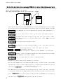
DANGER
Indicates a hazardous situation which may result in death or serious injury if it is handled
improperly.
CAUTION
Indicates a hazardous situation which may result in moderate or minor injury or only in
property damage if it is handled improperly. However, such a situation may lead to serious
consequences depending on circumstances.
CAUTION
z
z
z
z
z
[Installation]
Install the inverter on a metallic or non-flammable surface.
Otherwise, it may cause a fire.
Do not place flammable materials near the inverter.
Doing so may cause a fire.
Do not carry the inverter by the front cover.
The inverter may drop and cause personal injury.
Install the inverter on the surface that withstands its weight.
Otherwise, it may drop and cause personal injury.
Do not install or operate the inverter if it is damaged or have any of its parts missing.
Operating the inverter in such a state may cause personal injury.
DANGER
z
z
z
z
Before wiring, make sure the power is OFF.
Failure to do so may cause an electric shock or a fire.
Make sure to connect grounding wire.
Failure to do so may cause an electric shock or a fire.
Wiring must be done by skilled technicians.
Wiring by unauthorized persons may cause an electric shock or a fire.
Wire the inverter after it is installed.
Failure to do so may cause an electric shock or a fire.
CAUTION
z
z
z
z
2
[Wiring]
[Wiring]
Do not connect AC power to the output terminals (U, V or W).
Doing so may cause an injury or a fire.
Make sure that the rated voltage of the devise is conformed to the voltage of AC power.
If not, injury or a fire may occur.
Do not connect a resistance directly to the DC terminal +
○1or between +
○2 and −
○ or +
○1 and +
○2.
Doing so may cause a fire.
Connect a designated ground-fault protection relay or ground-fault breaker to the inverter input R, S and T for ground-fault
protection.
Failure to do so may cause an electric shock or a fire.
Induction motor vector mode
DANGER
z
z
z
z
z
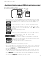
[Operation]
Turn the power ON after fitting the front cover. Do not remove the cover while the power is ON.
Failure to do so may cause an electrical shock.
Do not operate any switch with wet hands.
Failure to do so may cause an electrical shock.
Do not touch the inverter terminals while the power is ON even if the inverter is in the idle state.
Failure to do so may cause an electrical shock
The stop button is effective only when the use of its function has been set. Provide a separate emergency stop button.
There is possibility of personal injury.
If the alarm is reset with the operation signal kept input, the inverter will suddenly restart. Reset the alarm after making
sure that the operation signal is OFF
Failure to do so may cause personal injury.
CAUTION
z
z
z
The radiating fin and the radiating resistance are hot. Do not touch them.
There is a risk of burn.
The inverter can be set to operate in a wide range of speed. Operate the inverter after sufficiently checking the allowable
range of the motor and equipment.
Failure to do so may cause personal injury.
If a holding brake is necessary, provide it separately.
Failure to do so may cause personal injury.
DANGER
z
z
z
[Maintenance, inspection and parts replacement]
Before inspecting the inverter, turn the power OFF, and wait for 10 minutes or more to make sure that the motor is stopped.
Check the DC voltage between +
○1 and −
○ or +
○2 and −
○ to confirm that the voltage is 30V or less.
Failure to do so may cause an electric shock or a fire.
Check that the rated voltage of the devise is conformed to the voltage of AC power.
If not, personal injury or a fire may occur.
Unauthorized persons shall not perform maintenance or inspection of the inverter or part replacement. Use insulated tools
for maintenance and inspection.
Failure to do so may cause an electrical shock or a personal injury.
DANGER
z
[Operation]
[Other]
Never modify the inverter.
Doing so may cause an electrical shock or personal injury.
CAUTION
[General precautions]
Some illustrations given in this manual show the inverter from which the covers or safety shields have been removed to illustrate
the details. Before operating the inverter, reinstall the covers and shields to their original positions and operate the inverter
according to this manual.
These safety precautions and specifications stated in this manual are subject to change without notice.
3
Induction motor vector mode
Table of contents
For safety......................................................................................................................................................................................... 2
Chapter1
FULL mode........................................................................................................................................................... 6
1.1.
Feature of FULL mode................................................................................................................................................ 6
1.2.
Switching to Induction motor vector mode.............................................................................................................. 8
1.3.
Switching to FULL mode............................................................................................................................................ 9
1.4.
Automatic tuning .......................................................................................................................................................10
1.4.1.
Description of automatic tuning.....................................................................................................................10
1.4.2.
Requirement for automatic tuning ................................................................................................................ 11
1.4.3.
Procedure of automatic tuning........................................................................................................................12
Chapter2
Parameter change from the console................................................................................................................14
Chapter3
List of Induction motor vector mode parameter............................................................................................15
3.1.
Basic set-up area ........................................................................................................................................................15
3.2.
A-area (Max. motor speed, motor rating, parameter setting areas).................................................................16
3.3.
b-area (Operation mode, operation sequence setting area).............................................................................17
3.4.
c-area (Multi-function input related setting area) ............................................................................................19
3.5.
d-area (Acceleration/deceleration time, speed jump function, MRH function selection area).....................20
3.6.
E-area (Torque limit, torque command characteristics, vector control related setting area) ...................21
3.7.
F-area (Built-in DB (dynamic brake) operation, protection function, trace back setting area) ...............22
3.8.
G-area (Analog input/output setting area).........................................................................................................23
3.9.
H-area (Multi-function output setting area) ......................................................................................................25
3.10.
i-area (Droop control, mechanical loss compensation setting area)...............................................................26
3.11.
J-area (Digital communication option setting area).........................................................................................27
3.12.
L-area (Input gain, output gain setting area)....................................................................................................29
3.13.
n-area (Monitor adjusting area) ...........................................................................................................................29
3.14.
o- area (Factory adjustment area)........................................................................................................................30
3.15.
P-area (Built-in PLC, P resistor setting area)....................................................................................................30
3.16.
S-area (Mode selection, analog input/output adjusting area).........................................................................30
Chapter4
4
Description of Induction motor vector mode parameter..............................................................................32
4.1.
Basic set-up area ........................................................................................................................................................32
4.2.
A-area
4.3.
b-area (Operation mode, operation sequence setting area).............................................................................39
4.4.
c-area (Multi-function input related setting area) ............................................................................................48
4.5.
d-area (Acceleration/deceleration time, speed jump function, MRH function selection area).....................53
4.6.
E-area (Torque limit, torque command characteristics, vector control related setting area) ...................57
4.7.
F-area (Built-in DB (dynamic brake) operation, protection function, trace back setting area) ...............60
4.8.
G-area (Analog input/output setting area).........................................................................................................67
4.9.
H-area (Multi-function output setting area) ......................................................................................................73
4.10.
i-area (Droop control, mechanical loss compensation setting area)...............................................................77
(Max.motor speed, motor rating, parameter set-up areas)..............................................................34
Induction motor vector mode
4.11.
J-area (Digital communication option setting area).........................................................................................84
4.12.
L-area (Input gain, output gain setting area)....................................................................................................86
4.13.
n-area (monitor adjusting area)............................................................................................................................87
4.14.
o- area (Factory adjustment area)........................................................................................................................88
4.15.
P-area (Built-in PLC, P resistor setting area)....................................................................................................88
4.16.
S-area (Mode selection, analog input/output adjusting area).........................................................................89
Chapter5
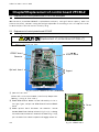
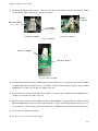
Replacement of control board VFC66-Z........................................................................................................102
5.1.
Replacement of control printed board VFC66-Z with stock parts ..................................................................102
5.2.
Replacement of control printed board VFC66-Z.................................................................................................102
5.3.
Initialization of VF66B............................................................................................................................................104
5.4.
Adjustment of Analog input gain ..........................................................................................................................105
Chapter6
Spare parts and technical assistance............................................................................................................106
5
Induction motor vector mode
Chapter1
FULL mode
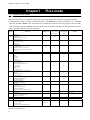
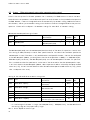
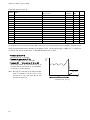
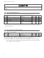
1.1. Feature of FULL mode
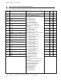
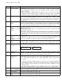
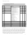
This inverter has total of 16 areas from A through S areas as described in table below. Unlike the SIMPLE mode, which only the
parameter of limited area can be displayed/changed, in the FULL mode, all parameter of all area can be displayed/changed.
* If setting change is made in the FULL mode and then return to the SIMPLE mode, the items indicated by “○” in “Default
value when operated in SIMPLE mode” column will be set to default value. However, if areas C through P are set in the FULL
mode and change the mode to SIMPLE mode once and then back to the FULL mode again, the values previously set in the
FULL mode will be selected for the areas C through P.
Set area
Description
SIMPLE mode
Distinguishable between
Default value when
1st set up block and
operated in SIMPLE
2nd set up block*1
mode
Remarks
Speed setting
Basic
Jog speed setting
Acceleration/deceleration time (1) and (2)
○
○
○
○
○
○
Speed control PI gain and etc.
Max. speed
A
Motor rating, with/without PG
Motor constant
Rewrite protection
Stop mode and its speed
b
Instantaneous power failure/ reverse prohibition
Operation/Jog/rotation speed command input place select
Torque limit
c
Contact input (multi-function input) function selection
△
○
○
○
○
○
○
○
△
○
○
○
○
○
△
○
Standard terminal can be selected
Acceleration/deceleration time (3) and (4), and S-pattern acceleration/deceleration
setting
d
Preset speed
Jump speed
MRH related
Torque command mode
Regeneration stall prevention
Motor temperature compensation ON/OFF
E
Current control gain
Torque control mode
Simulation mode
Forward direction change
Over speed/over load/over torque protection related
F
Trace back
Cumulative operation timer
Other protection related
Analog input/output characteristics selection of optional circuit board.
G
Temperature detection option related
Line speed monitor adjustment
H
Multi-function output selection
Data related to multi-function output
Built-in PLC
Drooping related
i
Operation mode (ASR/ATR/Priority)
2nd Speed control gain and etc.
Speed control method selection, position setting and etc.
J
Communication option related
Vdc adjusting gain
L
Set via S area
△
Analog input/output adjusting gain and offset
SIMPLE /FULL mode selection
n
Inverter mode, inverter capacity
○
P
For built-in PLC
△
Set via S area
○
Automatic measuring/initialization
S
Cumulative operation timer reset
ROM rewrite protection
Data in this area is not stored.
Limited part only
△
-
(Only limited portion is rewritable in SIMPLE mode)
*1:The parameters which are distinguishable between 1st set up block and 2nd set up block are indicated by “○”, whereas common
parameters are indicated by “△”.
6
Induction motor vector mode
About the SIMPLE and FULL modes
1
VF66B has two modes: SIMPLE mode and FULL mode.
Description
Only the parameters required for basic operation can be displayed/changed.
All parameters can be displayed/changed.
SIMPLE mode
FULL mode
This manual describes FULL mode. For instruction for SIMPLE mode, please refer to the Operation manual (basic operation
version).
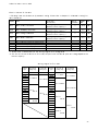
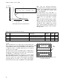
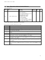
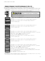
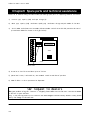
About the 1st and 2nd set-up blocks
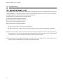
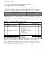
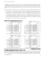
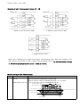
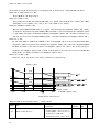
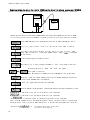
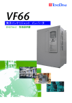
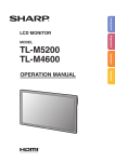
VF66B has two set up blocks 1st and 2nd; each set up block can set up inverter mode and parameter separately. VF66B
permits selection of either sensor-less drive or sensored drive for one motor, or switching between two motors; ED motor and
induction motor*1 (note: two motors can not be operated simultaneously). It is possible to know current usage of the set up
block; 1st or 2nd, or which inverter mode out of three modes is currently used on the 1st and 2nd set up blocks by checking
display on the console panel when the inverter is turned on.
*1: In case of switching between two motors, it is necessary to have contactors to switch motor wirings.
Note: For the method of switching between 1st set up block and 2nd setup block is done by external signal. Please refer to
Chapter3 3.4 <C- area>, also Chapter4 4.4 <C -area> in Chapter 4.
VF66B inverter
Contactor
Contactor
Induction motor
ED motor
Induction motor
Using both 1st and 2nd set up blocks, and use of
contactors,
switching
VF66B Inverter
between
two
different
motors
becomes possible. (Two motors cannot be operated
ED motor
Motors cannot be operated with direct connection to the
inverter.
simultaneously )
7
Induction motor vector mode
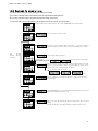
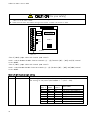
1.2. Switching to Induction motor vector mode
A method for switching inverter mode into Induction motor vector mode is described below.
Note: This inverter has two set up blocks; 1st set up block and 2nd set up block, and user can select from them. In the default setting, 1st set up
block is selected. For the switching method between 1st set up block and 2nd set up block, please refer to Chapter3 3.4 “C area” and
Chapter4 4.4 “C area”.
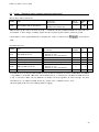
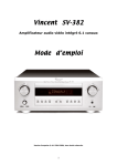
①Press [MONI/FNC] key to FNC (function selection) mode. (LED-FNC will be lit)
②Use [↑][↓] keys to select “S-00”. Press [SET] to confirm it.
③Use [JOG/→] key to shift the digit to the right, and [↑][↓] keys to enter a number “1040”, and then
press [SET] key to confirm it. If you input number except 「1040」,
is displayed on the console.
④“S-00” will appear again. Press [SET] to confirm.
⑤Use [JOG/→][↑][↓] keys to enter “2”, then press [SET] key to confirm.
will be displayed sequentially.
A message of
⑥“SurE”will be blinking on the display, press [SET] key to confirm.
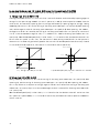
⑦Selection for the 1st set-up block is displayed. Select “V” for Induction motor vector mode. To change
inverter mode, use [↑][↓] keys to select a mode, press [SET] key to confirm the selection.
o:Induction motor V/f mode
V:Induction motor vector mode
E:ED motor vector mode
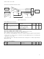
⑧Selection for the 2nd set-up block is displayed. Select an inverter mode from “o”, “V”or “E”using
[↑][↓] keys. Press [SET] to confirm the selection.
<In case of left figure, Induction motor vector mode has been selected for the 2nd set-up mode.>
is displayed for approx. 1sec. then displays
, and inverter mode change is completed.
Approx. 5sec. later, the display will return to display inverter type, capacity and voltage.
8
Induction motor vector mode
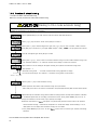
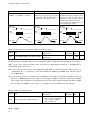
1.3. Switching to FULL mode
Method to switch between FULL mode and SIMPLE mode is described below:
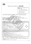
①Press [MONI/FNC] key to FNC (function selection) mode. (LED-FNC will be lit)
②Use [↑][↓] keys to select “S-00”. Press [SET] to confirm.
③Use [JOG/→] key to shift the digit to the right, and [↑][↓] keys to enter a number “1040”,
and then press [SET] to confirm. If you input number except 「1040」,
is displayed on
the console
④“S-00” will appear again. Press [SET] to confirm.
⑤Use [JOG/→][↑][↓] keys to enter “4”, then press [SET] to confirm.
・To change from SIMPLE mode into FULL mode, alternative display of “FuLL” and ”SurE”
will appear. Press [SET] to confirm the change.
・To change from FULL mode into SIMPLE mode, alternative display of “SnPL” and “SurE”
will appear. Press [SET] to confirm the change.
Note: SIMPLE mode is selected as a factory default setting.
9
Induction motor vector mode
1.4. Automatic tuning
1.4.1. Description of automatic tuning
In the Induction motor vector mode, control is made based on the parameter of the motor, so that parameter of the motor is
required. VF66B has an automatic tuning function which measures required information of the motor and set the parameter
automatically. Before the operation, automatic tuning must be performed.
In the Induction motor mode, there are four automatic tunings:
① FULL mode automatic tuning (Forward rotation)
② FULL mode automatic tuning (Reverse rotation)
③ DC mode automatic tuning (Forward rotation)
④ DC mode automatic tuning (Reverse rotation)
・ “Full mode automatic tuning” measures all required parameters.
・ “DC mode automatic tuning” measures only part of required parameters: primary resistance and dead time compensation.
Note: Under normal conditions, perform “FULL mode automatic tuning (Forward rotation)” and “DC mode automatic tuning
(Forward rotation)”. Only when each automatic tuning (Forward rotation) cannot be performed due to the relationship with
load equipment etc., then each automatic tuning (Reverse rotation) should be performed.
Note: When automatic tuning is performed, temperature of the motor must be cool enough (less than 25℃), otherwise due to
effect on the motor characteristics, correct measurement cannot be achieved.
10
Induction motor vector mode
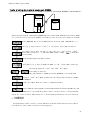
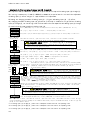
1.4.2. Requirement for automatic tuning
In order to perform automatic tuning, following conditions are required:
① The motor automatic tuning to be performed must be separated from load equipment.
② The motor automatic tuning to be performed must have rating of the motor.
To set motor rating, set the setting items A-00 through A-07 from the console panel (see below).
r/min
Hz
A
V
FNC
DIR
If LED of“FNC”on the console panel is not lit, press [MONI/FNC] key to light “FNC”.
RUN
JOG
REV
ALM
FWD
MONI
SET
START
FNC
REV
JOG
STOP
→
RESET
r/min
Hz
A
V
FNC
DIR
Use [↑][↓] keys to select “A-00”.
RUN
JOG
REV
ALM
FWD
MONI
SET
START
FNC
REV
JOG
STOP
→
RESET
r/min
Hz
A
V
FNC
DIR
START
FNC
(A-02)
through
(A-07)
same way.
number correspond to the item to be set, then press [SET] key to confirm.
FWD
MONI
SET
Set
Use [JOG/→] key to shift the digit to right, and [↑][↓] keys to select a
RUN
JOG
REV
ALM
REV
JOG
STOP
→
RESET
r/min
Hz
A
V
FNC
DIR
Current setting data is displayed.
RUN
JOG
REV
ALM
FWD
MONI
SET
START
FNC
REV
JOG
STOP
→
RESET
r/min
Hz
A
V
FNC
DIR
RUN
JOG
REV
ALM
FWD
MONI
SET
START
FNC
To select data
Use[↑][↓]keys to select data
Write data into the inverter. Use [JOG/→] key to shift the digit to the right,
and [↑][↓] keys to change a number, then press [SET] to confirm. To set
negative value, enter the value to leftmost digits.
REV
JOG
STOP
→
RESET
In case data cannot be written:
Above setting range
r/min
Hz
A
V
FNC
DIR
RUN
JOG
REV
ALM
Below setting range
Prohibited [set by (b-00)]]
After the confirmation of setting by [SET] key, “A-00” (selection item)
will appear again.
FWD
MONI
SET
START
FNC
REV
JOG
STOP
→
RESET
r/min
Hz
A
V
FNC
DIR
RUN
JOG
REV
ALM
Press [MONI/FNC] key to turn off the LED of FNC. Monitor item such as
“SPd” will be displayed for approx. 1sec.
FWD
MONI
START
SET
FNC
REV
JOG
STOP
→
RESET
1sec. later
r/min
Hz
A
V
FNC
DIR
RUN
JOG
REV
ALM
MONI
setting.
FWD
SET
START
FNC
Approx. 1sec. later, data display will change to show monitor item of current
REV
JOG
STOP
→
RESET
<In case of left figure, the display indicates rotation speed is 0 rpm.>
11
Induction motor vector mode
1.4.3. Procedure of automatic tuning
・Procedure for FULL mode automatic tuning
Below is a concrete procedure for FULL mode automatic tuning.
CAUTION
[Relating to FULL mode automatic tuning]
Motor will turn during the FULL mode automatic tuning. Please separate the motor from load equipment and perform the tuning as a motor alone,
otherwise may cause damage to the equipment or personal injury.
①Press [MONI/FNC] key to FNC (function selection) mode. (LED-FNC will be lit)
②Use [↑][↓] keys to select “S-00”. Press [SET] to confirm it.
③Use [JOG/→] key to shift the digit to the right, and [↑][↓] keys to enter a number “1040”, and then
is displayed on the console
press [SET] key to confirm it. If you input number except 「1040」,
④“S-00” will appear again. Press [SET] to confirm.
⑤Use [JOG/→][↑][↓] keys to select a mode of automatic tuning. For FULL mode automatic tuning, enter
“10” (Forward rotation) or “11” (Reverse rotation). Press [SET] to confirm the selection.
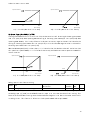
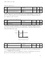
⑥An indication as on the left figure will appear showing set-up block and automatic tuning mode.
・Set-up block: ‘1’
・Automatic tuning mode: ‘ ’ for FULL mode automatic tuning (rightmost is empty).
Set-up block
<In case of the left figure, set-up block is 1, automatic tuning mode is FULL mode>
Automatic tuning mode
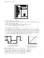
⑦Press [JOG/→] key to start automatic tuning.
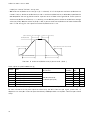
* Motor operation when FULL mode automatic tuning (Four-pole motor)
After slowly turns about 1/2 rotation, accelerated to the speed approximately 80% of rated rotation speed.
⑧Automatically the automatic tuning finishes. When the tuning finishes normally without problem, indication
of “tunEd”will appear after the recording of measurement result. Press [STOP/RESET] key for 3 sec. to
change the indication to show inverter type, capacity and voltage.
*Indication of protection of
will appear if any abnormality presents. Please refer to the operation
manual (trouble shooting / maintenance), Chapter2 2.1.2 <Protection display and its handling> or 2.1.4
<Description of error display when automatic tuning> for more detail.
・Press [STOP/RESET] key for 3 sec. to reset
indication.
* For the detail of S-area, please refer to Chapter4, 4.16 <S-area>.
12
and to return to inverter type, capacity and voltage
Induction motor vector mode
・Procedure for DC mode automatic tuning
Below is a concrete procedure for DC mode automatic tuning:
CAUTION
[Relating to DC mode automatic tuning]
Motor will turn during DC mode automatic tuning in the Induction motor vector mode. In order to prevent mechanical damage, please separate the
motor from the equipment or release mechanical brake so that motor can rotate freely.
①Press [MONI/FNC] key to FNC (function selection) mode. (LED-FNC will be lit)
②Use [↑][↓] keys to select “S-00”. Press [SET] to confirm.
③Use [JOG/→] key to shift the digit to the right, and [↑][↓] keys to enter a number “1040”, and then
is displayed on the console
press [SET] key to confirm. If you input number except 「1040」,
④“S-00” will appear again. Press [SET] to confirm.
⑤Use [JOG/→][↑][↓] keys to select a mode of automatic tuning. For DC mode automatic tuning, enter
“12” (Forward rotation) or “13” (Reverse rotation). Press [SET] to confirm the selection.
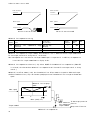
⑥An indication as on the left figure will appear showing set-up block and automatic tuning mode.
・Set-up block: ‘1’
・Automatic tuning mode: ‘d’ for DC mode automatic tuning.
Set-up block
<In case of the left figure, set-up block is 1, automatic tuning mode is DC mode>
Automatic tuning mode
⑦Press [JOG/→] key to start automatic tuning.
* Motor operation when DC mode automatic tuning (Six-pole motor)
Slowly turns to forward direction up to 2/3 rotation.
⑧Automatically the automatic tuning finishes. When the tuning finishes normally without problem, indication
of “tunEd”will appear after the recording of measurement result. Press [STOP/RESET] key for 3 sec. to
change the indication to show inverter type, capacity and voltage.
*Indication of protection or
will appear if any abnormality presents. Please refer to the operation
manual (trouble shooting / maintenance), Chapter2, 2.1.2 <Protection indication and its handling> or 2.1.4
<Description of error indication when automatic tuning> for more detail.
・Press [STOP/RESET] key for 3 sec. to reset
and to return to inverter type, capacity and voltage
indication.
* For the detail of S-area, please refer to Chapter4, 4.16 <S-area>.
13
Induction motor vector mode
Chapter2
Parameter change from the console
Below is a concrete procedure to change parameters from the console:
r/min
Hz
A
V
FNC
DIR
If LED of “FNC” on the console panel is not lit, press [MONI/FNC] key to light “FNC”.
RUN
JOG
REV
ALM
FWD
MONI
SET
START
FNC
REV
JOG
STOP
→
RESET
r/min
Hz
A
V
FNC
DIR
RUN
JOG
REV
ALM
Basic set-up area “0.SrEF” is displayed. Use [↑][↓] keys to move
to desired set-up items.
FWD
MONI
START
SET
FNC
REV
JOG
STOP
→
RESET
r/min
Hz
A
V
FNC
DIR
RUN
JOG
REV
ALM
For the A through S areas, you can move to other set-up areas while
alphabet part is blinking.
FWD
MONI
START
SET
FNC
REV
JOG
STOP
→
RESET
r/min
Hz
A
V
FNC
DIR
RUN
JOG
REV
ALM
Please refer to Chapter3 <List of the Induction motor vector mode
JOG
STOP
parameter> and Chapter4 <Description of the Induction motor vector mode
→
RESET
SET
FNC
parameter, then press [SET] key to confirm.
START
FWD
MONI
Use [JOG/→] key to shift the digit to right, and [↑][↓] keys to change a
REV
parameters>.
<Left figure showing set up of the item “b-11”>
r/min
Hz
A
V
FNC
DIR
RUN
JOG
REV
ALM
START
FNC
REV
JOG
STOP
→
RESET
r/min
Hz
A
V
RUN
JOG
REV
ALM
MONI
<In case of the left figure, parameter is set to “1”.>
The parameter you changed is once again displayed.
<Left figure is indicating set-up of the item “b-11”>
FWD
START
SET
FNC
REV
JOG
STOP
→
RESET
r/min
Hz
A
V
FNC
DIR
RUN
JOG
REV
ALM
MONI
START
FNC
Press [MONI/FNC] key to turn off the LED of FNC. Monitor item such as
“SPd” will be displayed for approx. 1sec. then the data of monitor will be
FWD
SET
14
number.
FWD
MONI
SET
FNC
DIR
Use [↑][↓] keys to select appropriate number, press [SET] to confirm the
REV
JOG
STOP
→
RESET
displayed.
Induction motor vector mode
Chapter3 List of Induction motor vector mode parameter
Below are lists of parameters for Induction motor vector mode for each item in each area.
* For description of each parameter, please refer to Chapter4, <Description of Induction motor vector mode parameter>.
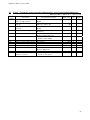
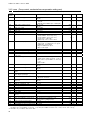
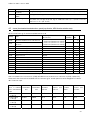
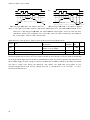
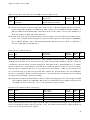
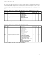
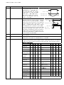
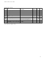
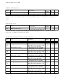
3.1. Basic set-up area
Rewritable when in operation: Y = Yes N = No
Console
display
0.SrEF
1.FJoG
2.rJoG
3.Acc1
4.dEc1
5.Acc2
6.dEc2
7.ASrP
8.ASrI
9.ASrJ
Set-up items
Speed command
Forward JOG speed
Reverse JOG speed
Acceleration time(1)
Deceleration time(1)
Acceleration time(2)
Deceleration time(2)
Speed control proportiongain(1)
Speed control integral time
constant(1)
Speed control system moment of
inertia(1)
Set-up range (item selection)
-Maximum speed (A-00) to Maximum speed
(A-00)
Minimum speed (A-01) to up to 300
-300 to -Minimum speed (A-01)
0.0 to 3600.0
0.0 to 3600.0
0.0 to 3600.0
0.0 to 3600.0
3 to 50
20 to 10000
0 to 65535
Default setting
Unit
Rewritable
0
r/min
Y
24
-24
30.0
30.0
0.3
0.3
15
40
r/min
r/min
sec
sec
sec
sec
msec
Y
Y
Y
Y
Y
Y
Y
Y
gm2
Y
10
15
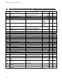
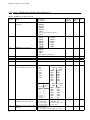
Induction motor vector mode
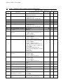
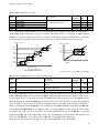
3.2. A-area (Max. motor speed, motor rating, parameter setting areas)
Rewritable when in operation: Y = Yes N = No
Console
display
Set-up items
A-00
A-01
Maximum speed
Minimum speed
A-02
Rated motor capacity
A-03
Rated motor voltage
A-04
A-05
A-06
A-07
Rated motor current
Rated motor speed
Number of motor pole
Rated motor frequency
A-08
A-09
A-10
Number of PG-pulse
PWM carrier frequency
PG selection
A-11
A-12
A-13
A-14
A-15
A-16
A-17
A-18
A-19
A-20
A-21
DeadTime compensation (U/ phase+side)
DeadTime compensation (U/ phase-side)
DeadTime compensation (V/ phase+side)
DeadTime compensation (V/ phase-side)
DeadTime compensation (W/ phase+side)
DeadTime compensation (W/ phase-side)
Motor primary resistance
Motor secondary resistance
Motor leakage inductance
Motor mutual inductance
Motor inductance saturation
coefficient(1)
Motor inductance saturation
coefficient(2)
Motor core loss torque compensation
Motor loss coefficient(1)
Motor loss coefficient(2)
A-22
A-23
A-24
A-25
Set-up range (item selection)
Unit
Rewritable
1800
12
r/min
r/min
N
Y
0.00
kW
N
0
V
N
0.00
0
4
0.0
A
r/min
Pole
Hz
N
N
N
N
600
6.0
0
P/R
kHz
―
N
N
N
0.00
0.00
0.00
0.00
0.00
0.00
0.0*3
0.0*3
0.0*3
0.0*3
0.0
μsec
μsec
μsec
μsec
μsec
μsec
mΩ
mΩ
mH
mH
%
N
N
N
N
N
N
N
N
N
N
N
0.0 to 50.0
0.0
%
N
0.0 to 20.0
0.0 to 200.0
0.0 to 200.0
0.0
0.0
0.0
%
%
%
N
N
N
300 to 14700
(Depends on A-10 setting)*1 up to Maximum speed
(A-00)
(Min. depends on inverter)*2 up to rated
capacity of the inverter*
(200V class) 70 to 230
(400V class) 140 to 460
20% - 150% of inverter’s rated current
20% - 100% of Max.speed
2 - 12
Rated speed×number of pole /120 to rated speed
×number of pole/120+7.0
60 to 3600
1.0 to 6.0
0:S-mode sensor-less drive
1:V-mode drive with PG (AB phase input)
0.00 to 9.99
0.00 to 9.99
0.00 to 9.99
0.00 to 9.99
0.00 to 9.99
0.00 to 9.99
(Setting range differs depend on inverter
capacity)*2
(Setting range differs depend on inverter
capacity)*2
0.0 to 50.0
Default setting
*If rated voltage of the motor is larger than 190V (200V class) / 380V (400V class), the maximum value of the
setting range will be proportionally larger.
*1: The minimum value for A-01 setting is 12 when A-10=0, and 0 when A-10=1.
*2: Please refer to Chapter4 4.2 <A-area> for the minimum value for A-02, setting ranges of A-17/A-18 and
A-19/A-20.
*3: For the initialization data for A-17 to A-20, the position of the decimal point will change depend on the
inverter capacity.
16
Induction motor vector mode
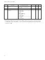
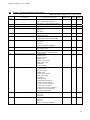
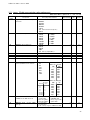
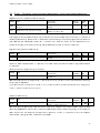
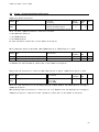
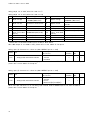
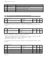
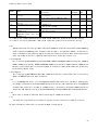
3.3. b-area (Operation mode, operation sequence setting area)
Rewritable when in operation: Y = Yes N = No
Console
display
b-00
Setting data rewrite protection
OFF (Inactive)
ON (Activate protection)
b-01
Stop mode selection
b-02
b-03
b-04
Stop speed
DC brake operation time
DC brake gain
0: Free stop
1: Deceleration stop
2: Deceleration stop with DC brake
0 to 300
0.0 to 10.0
20.0 to 500.0
b-05
JOG stop mode selection
b-06
b-07
JOG stop speed
Instantaneous power interruption
restart
Reverse
prohibition
mode
selection
b-08
Set-up items
Set-up range (item selection)
0: Free stop
1: Deceleration stop
2: Deceleration stop with DC brake
0 to 300
OFF (Inactive)
ON (Active)
0: Normal
1: Prohibition of nonconforming rotation
against command
2: Reverse prohibition
0: Terminal block
1: Console (SET66-Z)
2: Digital communication option
0: Coupled
1: Analog input(1)[terminal block](AIN1)
2: Console (SET66-Z)
3: Digital communication option
4: Analog input(2)[terminal block for
IO66-Z option or digital communication
option](AIN2)
5: (For future extension option)*1
6: Analog input(3)[IO66-Z option terminal
block](AIN3)
7: Built-in PLC
0: Coupled
1: Terminal block
2: Console (SET66-Z)
3: Digital communication option
0: Coupled
1: Terminal block
2: Console (SET66-Z)
3: Digital communication option
0 to the value depend on Rated motor current
(A-04)*2
- value depend on Rated motor current
(A-04) *2 to 0
b-09
Commanding place when coupled
b-10
Speed commanding place selection
b-11
Operation
selection
b-12
JOG commanding place selection
b-13
Forward powering torque limit
b-14
Forward regenerative torque
limit
Reverse powering torque limit - value depend on Rated motor current
b-15
commanding
place
b-16
Reverse regenerative torque
limit
b-17
Analog
speed
command
characteristic selection
b-18
Analog speed command upper limit
speed
(A-04) *2 to 0
0 to the value depend on Rated motor current
(A-04)*2
0: 0 to ±10V
1: 0 to 10V
2: 4 to 20mA
Absolute value of Analog speed command
lower limit speed (b-19) to 100.0
Default setting
Unit
Rewritable
OFF
―
N
1
―
Y
r/min
sec
%
Y
Y
Y
―
Y
r/min
―
Y
N
0
―
N
1
―
N
0
―
N
0
―
N
0
―
N
150
%
Y
-150
%
Y
-150
%
Y
150
%
Y
1
―
N
100.0
%
Y
30
0.0
100.0
0
30
OFF
17
Induction motor vector mode
Console
display
b-19
b-20
b-21
Set-up items
Set-up range (item selection)
Analog speed command lower limit
speed
-Analog speed command upper limit speed
(b-18) to Analog speed command upper limit
speed (b-18)
0.000 to 1.000
0: Output voltage
1: output current
2: Torque command
3: Speed
4: Speed command
5: Built-in PLC output
6: Calibration
7: Internal monitor
-1: 6F frequency
-2: 6F speed
-3: 6F calibration
Analog input ZeroLimit voltage
Analog output(1) characteristic
selection
Default setting
Unit
Rewritable
0.0
%
Y
0.000
1
V
―
Y
N
*1: b-10=5 is for a future extension option. Under normal conditions, please do not use this setting.
*2: The maximum (minimum) value for torque limit will be 200×(rated current of inverter) / the value calculated
from Rated motor current (A-04). However, in case if calculated value exceeds 200%, then the maximum (minimum)
value will be 200%.
18
Induction motor vector mode
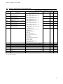
3.4. c-area (Multi-function input related setting area)
Rewritable when in operation: Y = Yes N = No
Console
display
c-00
c-01
c-02
c-03
c-04
c-05
c-06
c-07
c-08
c-09
c-10
c-11
c-12
c-13
c-14
c-15
c-16
c-17
Set-up items
Set-up range (item selection)
Multifunction
input
place
selection
Multifunction input terminal(1)
function selection
Multifunction input terminal(2)
function selection
Multifunction input terminal(3)
function selection
Multifunction input terminal(4)
function selection
Multifunction input terminal(5)
function selection
Multifunction input terminal(6)
function selection
Multifunction input terminal(7)
function selection
Multifunction input terminal(8)
function selection
Multifunction input terminal(9)
function selection
Multifunction input terminal
(10) function selection
Multifunction input terminal
(11) function selection
Multifunction input terminal
(12) function selection
Multifunction input terminal
(13) function selection
Multifunction input terminal
(14) function selection
Multifunction input terminal
(15) function selection
Multifunction input terminal
(16) function selection
Multifunction input terminal
(17) function selection
0: Terminal block
1: Digital communication option
0: Preset speed selection 1
1: Preset speed selection 2
2: Preset speed selection 3
3: Accel./decel. time selection 1
4: Accel./decel. time selection 2
5: Speed up command (MRH mode)
6: Speed down command (MRH mode)
7: Speed hold
8: S-pattern accel./decel. prohibition
9: Max. speed reduction
10: Droop control disabled
11: Speed/torque control selection
12: Forward/reverse operation command
selection
13: DC brake command
14: Initial excitation command
15: External failure signal 1
(protection relay 86A enabled)
16: External failure signal 2
(protection relay 86A enabled)
17: External failure signal 3
(protection relay 86A enabled)
18: External failure signal 4
(protection relay 86A enabled)
19: External failure signal 1
(protection relay 86A disabled)
20: External failure signal 2
(protection relay 86A disabled)
21: External failure signal 3
(protection relay 86A disabled)
22: External failure signal 4
(protection relay 86A disabled)
23: Trace back external trigger
24: 2nd set-up block selection
25: Emergency stop (B contact)
26: No function
27: Speed commanding terminal block
selection
28: No function
29: Operation command [reverse] (STARTR)
30: Jog command [forward] (JOGF)
31: Jog command [reverse] (JOGR)
32: Emergency stop (A contact)
33: Protection reset (RESET)
34: External signal input 1
35: External signal input 2
36: External signal input 3
37: External signal input 4
Default setting
Unit
Rewritable
0
―
N
29
―
N
30
―
N
31
―
N
32
―
N
33
―
N
0
―
N
1
―
N
2
―
N
3
―
N
4
―
N
5
―
N
6
―
N
7
―
N
8
―
N
9
―
N
10
―
N
11
―
N
19
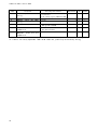
Induction motor vector mode
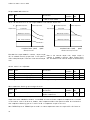
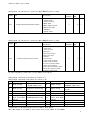
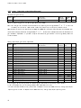
3.5. d-area (Acceleration/deceleration time, speed jump function, MRH function selection area)
Rewritable when in operation: Y = Yes N = No
Console
display
d-00
Set-up items
d-07
d-08
d-09
d-10
d-11
d-12
d-13
d-14
d-15
d-16
d-17
d-18
d-19
d-20
d-21
d-22
d-23
d-24
d-25
d-26
d-27
Acceleration/Deceleration
time
selection
JOG acceleration/deceleration time
selection
Acceleration time(3)
Deceleration time(3)
Acceleration time(4)
Deceleration time(4)
S-pattern acceleration/deceleration
usage selection
S-pattern rise time(1)
S-pattern acceleration reach time(1)
S-pattern fall time(1)
S-pattern deceleration reach time(1)
S-pattern rise time(2)
S-pattern acceleration reach time(2)
S-pattern fall time(2)
S-pattern deceleration reach time(2)
Preset speed(1)
Preset speed(2)
Preset speed(3)
Preset speed(4)
Preset speed(5)
Preset speed(6)
Preset speed(7)
Jump speed(1)
Jump speed(2)
Jump speed(3)
Jump speed(4)
Jump speed width
MRH function usage selection
d-28
MRH upper limit speed
d-29
MRH lower limit speed
d-30
Speed deviation limiting command
selection
Maximum deviation (positive)
Maximum deviation (negative)
d-01
d-02
d-03
d-04
d-05
d-06
d-31
d-32
20
Set-up range (item selection)
0: Accel./decel.
1: Accel./decel.
2: Accel./decel.
3: Accel./decel.
0.0 to 3600.0
0.0 to 3600.0
0.0 to 3600.0
0.0 to 3600.0
OFF (not use)
ON (use)
0.0 to 60.0
0.0 to 60.0
0.0 to 60.0
0.0 to 60.0
0.0 to 60.0
0.0 to 60.0
0.0 to 60.0
0.0 to 60.0
Time
Time
Time
Time
(1)
(2)
(3)
(4)
-Maximum speed (A-00)
to Maximum speed (A-00)
0 to Maximum speed (A-00)
0 to 300
OFF (not use)
ON (use)
MRH lower limit speed (d-29)
to Maximum speed (A-00)
-Maximum speed (A-00) to MRH upper limit
speed (d-28)
OFF (without limiting command)
ON (with limiting command)
0.0 to 100.0
-100.0 to 0.0
Default setting
Unit
Rewritable
0
―
N
1
―
N
30.0
30.0
30.0
30.0
OFF
sec
sec
sec
sec
―
Y
Y
Y
Y
N
0.1
0.1
0.1
0.1
0.1
0.1
0.1
0.1
0
0
0
0
0
0
0
0
0
0
0
0
OFF
sec
sec
sec
sec
sec
sec
sec
sec
r/min
r/min
r/min
r/min
r/min
r/min
r/min
r/min
r/min
r/min
r/min
r/min
―
Y
Y
Y
Y
Y
Y
Y
Y
Y
Y
Y
Y
Y
Y
Y
Y
Y
Y
Y
Y
N
300
r/min
Y
0
r/min
Y
OFF
―
Y
5.0
-5.0
%
%
Y
Y
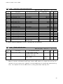
Induction motor vector mode
3.6. E-area (Torque limit, torque command characteristics, vector control related setting area)
Rewritable when in operation: Y = Yes N = No
Console
display
E-00
Set-up items
E-03
Regeneration stall prevention
function usage selection
Regeneration stall prevention
voltage
High-efficient
mode
usage
selection
Forward direction change
E-04
Simulation mode
E-05
Torque command mode selection
E-06
E-07
E-08
E-09
Flux reinforcing rate at start
Current control proportion gain
Current control integral gain(1)
Current control integral gain(2)
E-10
Motor temperature compensation
E-11
E-12
Flux-command
Motor cooling fan
(sensor-less drive)
E-01
E-02
Set-up range (item selection)
OFF (not use)
ON (use)
(200V class) 320 to 360
(400V class) 640 to 720
OFF (not use)
ON (use)
OFF (Forward)
ON (Reverse)
OFF (without simulated operation)
ON (with simulated operation)
0: % command
1: Absolute value command
100.0 to 150.0
40.0 to 200.0
20.0 to 500.0
20.0 to 500.0
OFF (without compensation)
ON (with compensation)
20.0 to 150.0
0: Self cooling fan
1: Forced air cooling fan
Default setting
Unit
Rewritable
OFF
―
N
340
680
OFF
V
Y
―
N
OFF
―
N
OFF
―
N
0
―
N
100.0
100.0
100.0
100.0
%
%
%
%
N
Y
Y
Y
OFF
―
N
100.0
0
%
―
N
N
21
Induction motor vector mode
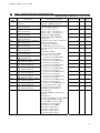
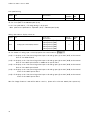
3.7. F-area (Built-in DB (dynamic brake) operation, protection function, trace back setting area)
Rewritable when in operation: Y = Yes N = No
Console
display
F-00
Built-in DB(DynamicBrake) operation level
F-01
F-02
F-03
F-04
Forward overspeed setting
Reverse overspeed setting
Overload protection setting
Cumulative operation timer(1-Capacitor)
(200V class) 320.0 to 360.0
(400V class) 640.0 to 720.0
0.0 to 150.0
-150.0 to 0.0
20 to 110
0 to 65535
F-05
Cumulative operation timer(2-Fan)
0 to 65535
F-06
Motor overheat protection operation
selection
Protection relay (86A) operation selection
upon power failure
Protection retry count setting
External failure(1) detection delay time
External failure(2) detection delay time
External failure(3) detection delay time
External failure(4) detection delay time
Traceback pitch
Traceback trigger point
Traceback CH1 selection
Traceback CH2 selection
Traceback CH3 selection
Traceback CH4 selection
Traceback CH5 selection
Traceback CH6 selection
Traceback CH7 selection
Traceback CH8 selection
Traceback CH9 selection
Traceback CH10 selection
Traceback CH11 selection
Traceback CH12 selection
Over torque protection function selection
F-07
F-08
F-09
F-10
F-11
F-12
F-13
F-14
F-15
F-16
F-17
F-18
F-19
F-20
F-21
F-22
F-23
F-24
F-25
F-26
F-27
F-28
F-29
F-30
F-31
F-32
Set-up items
Over torque protect level setting
Overtorque protection operation standard
torque
Speed control error function usage
selection
Speed control error detection speed width
(positive)
Speed control error detection speed width
(negative)
340.0
680.0
105.0
-105.0
100
on
V
Rewritabl
e
Y
%
%
%
Hr
N
N
Y
N
on
Hr
N
OFF (without protection operation)
ON (with protection operation)
OFF (without protection operation)
ON (with protection operation)
0 to 5
0.0 to 30.0
0.0 to 30.0
0.0 to 30.0
0.0 to 30.0
0 to 100
1 to 99
0 to 12
0 to 12
0 to 12
0 to 12
0 to 12
0 to 12
0 to 12
0 to 12
0 to 12
0 to 12
0 to 12
0 to 12
OFF (without over torque protection)
ON (with over torque protection)
110 to 205
50 to 105
OFF
―
N
OFF
―
N
0
0.0
0.0
0.0
0.0
1
80
0
0
0
0
0
0
0
0
0
0
0
0
ON
count
sec
sec
sec
sec
msec
―
―
―
―
―
―
―
―
―
―
―
―
―
―
Y
Y
Y
Y
Y
Y
Y
Y
Y
Y
Y
Y
Y
Y
Y
Y
Y
Y
Y
N
150
105
%
%
Y
Y
OFF (without speed control error
function)
ON (with speed control error function)
2.0 to 30.0
OFF
―
N
5.0
%
Y
-5.0
%
Y
Set-up range (item selection)
Default setting
Depend
inverter
capacity*1
Depend
inverter
capacity*1
-30.0 to -2.0
*1: Please refer to Chapter4 4.7 <F-area> for factory default data of F-04 and F-05.
22
Unit
Induction motor vector mode
3.8. G-area (Analog input/output setting area)
Rewritable when in operation: Y = Yes N = No
Console
display
G-00
Temperature detection selection
G-01
G-02
G-03
Temperature detection offset adjustment
Temperature detection gain adjustment
Analog input(2) characteristics selection
G-04
Analog input(2) upper limit speed
G-05
Analog input(2) lower limit speed
G-06
Analog input(3) characteristics selection
G-07
Analog input(3) upper limit speed
G-08
Analog input(3) lower limit speed
G-09
Analog output(2) characteristics selection
G-10
Analog output(3) characteristics selection
G-11
Analog input(4) characteristics selection
G-12
Analog input(5) characteristics selection
Set-up items
Set-up range (item selection)
0: not use
1: thermistor (TVTH66-Z, optional)
2: pt100 [thermocouple](TVPT66-Z, optional)
-20.0 to 20.0
50.0 to 150.0
0:0 to ±10V
1:0 to 10V
2:4 to 20mA
Absolute value of Analog input(2) lower limit
speed (G-05) to 100.0
-Analog input(2) upper limit speed (G-04) to
Analog input(2) upper limit speed (G-04)
0:0 to ±10V
1:0 to 10V
2: not use
3: Pulse train (0[Hz] to 150[kHz])
Absolute value of Analog input (3) lower limit
speed (G-08) to 100.0
-Analog input(3) upper limit speed (G-07) to
Analog input(2) upper limit speed (G-07)
0: Output voltage
1: Output current
2: Torque command
3: Motor speed
4: Motor speed command
5: Built-in PLC output
6: Calibration
7: Internal monitor
0: Output voltage
1: Output current
2: Torque command
3: Motor speed
4: Motor speed command
5: Built-in PLC output
6: Calibration
7: Internal monitor
8: Output voltage (4 to 20mA)
9: Output current (4 to 20mA)
10: Torque command (4 to 20mA)
11: Motor speed (4 to 20mA)
12: Motor speed command (4 to 20mA)
13: Built-in PLC output (4 to 20mA)
14: Calibration (12mA output)
0: 0 to ±10V
1: 0 to 10V
2: 4 to 20mA
0: 0 to ±10V
1: 0 to 10V
2: not use
3: Pulse train (0[Hz] to 150[kHz])
Default setting
Unit
Rewritable
0
―
N
0.0
100.0
1
℃
―
―
Y
Y
N
100.0
%
Y
0.0
%
Y
1
―
N
100.0
%
Y
0.0
%
Y
1
―
N
0
―
N
1
―
N
1
―
N
23
Induction motor vector mode
Console
display
G-13
Analog output(4) characteristics selection
G-14
Analog output(5) characteristics selection
G-15
G-16
Line speed monitor adjustment
Analog input monitor display selection
24
Set-up items
Set-up range (item selection)
Default setting
Unit
Rewritable
0: Output voltage
1: Output current
2: Torque command
3: Motor speed
4: Motor speed command
5: Built-in PLC output
6: Calibration
7: Internal monitor
0: Output voltage
1: Output current
2: Torque command
3: Motor speed
4: Motor speed command
5: Built-in PLC output
6: Calibration
7: Internal monitor
8: Output voltage (4 to 20mA)
9: Output current (4 to 20mA)
10: Torque command (4 to 20mA)
11: Motor speed (4 to 20mA)
12: Motor speed command (4 to 20mA)
13: Built-in PLC output (4 to 20mA)
14: Calibration (12mA output)
0.0 to 2000.0
1: Analog input (1) [AIN1]
2: Analog input (2) [AIN2]
3: Analog input (3) [AIN3]
4: Analog input (4) [AIN4]
5: Analog input (5) [AIN5]
2
―
N
3
―
N
0.0
1
―
―
Y
Y
Induction motor vector mode
3.9. H-area (Multi-function output setting area)
Rewritable when in operation: Y = Yes N = No
Console
display
H-00
H-01
H-02
H-03
H-04
H-05
H-06
H-07
H-08
H-09
H-10
H-11
H-12
Set-up items
Multifunction output
function selection
Multifunction output
function selection
Multifunction output
function selection
Multifunction output
function selection
Multifunction output
function selection
Multifunction output
function selection
Set-up range (item selection)
terminal(1)
terminal(2)
terminal(3)
terminal(4)
terminal(5)
terminal(6)
Speed detection(1)
Speed detection(2)
Speed detection width
Torque detection (with polarity)
Torque detection (absolute value)
Overload pre-alarm operation level
setting
Maximum speed reduction rate
0: not used
1: Motor speed detection (1)
(Motor speed = detection setting)
2: Motor speed detection (1)
(Motor speed ≧ detection setting)
3: Motor speed detection (1)
(Motor speed ≦ detection setting)
4: Motor speed detection (2)
(Motor speed = detection setting)
5: Motor speed detection (2)
(Motor speed ≧ detection setting)
6: Motor speed detection (2)
(Motor speed ≦ detection setting)
7: Reach setting
8: Torque detection
9: Torque detection (absolute value)
10: Power failure
11: Overload pre-alarm
12: Retrying
13: in reverse operation
14: Protection operation code゙
15: not used
16: in operation
17: (For future extension option)*1
18: Timer 1 elapse
19: Timer 2 elapse
20: 2nd set-up block selected
21: Fan motor failed
-Maximum speed (A-00) to Maximum speed (A-00)
-Maximum speed (A-00) to Maximum speed (A-00)
0 to
-205
0 to
0 to
600
to 205
205
100
50.0 to 100.0
Default setting
Unit
Rewritable
7
―
N
1
―
N
0
―
N
8
―
N
2
―
N
3
―
N
0
0
0
0
0
50
r/min
r/min
r/min
%
%
%
Y
Y
Y
Y
Y
Y
%
Y
90.0
*1: Selection 17 for H-00 through H-05 is for a future extension option. Under normal conditions, please do
not use this setting.
25
Induction motor vector mode
3.10. i-area (Droop control, mechanical loss compensation setting area)
Rewritable when in operation: Y = Yes N = No
Console
display
Set-up items
i-00
PLCL function usage selection
i-01
PLCH function usage selection
i-02
Droop control usage selection
i-03
i-04
i-05
i-06
i-07
Droop start speed
Droop rate changeover speed
Droop rate
Droop start torque
Operation mode selection
i-08
Torque command input place selection
i-09
i-10
i-11
i-12
i-13
Analog torque command gain
Speed control proportion gain(2)
Speed control integral time constant (2)
Speed control system moment of
inertia(2)
JOG proportion gain selection
i-14
ASR cancelation usage selection
i-15
ASR feed-forward usage selection
i-16
Variable structure proportion gain start
speed
Variable structure proportion gain
minimum gain percentage
Initial excitation selection*2
i-17
i-18
i-19
i-20
i-21
i-22
i-23
i-24
i-25
i-26
i-27
i-28
i-29
Mechanical loss compensation usage
selection
Mechanical loss offset amount
Gradient of mechanical loss
Positing speed(0)
Positing speed(1)
Positing acceleration time
Positing deceleration time
Creep speed
Number of moving pulse within a creep
period
Number of stop pulse
Positioning emergency stop selection
Set-up range (item selection)
OFF (not use)
ON (use)
0: OFF (not use)
1: PLCH ON
2: PLCH ON (speed command input = PLCH output)
OFF (not use)
ON (use)
0.0 to 100.0
0.0 to 100.0
0.0 to 50.0
0.0 to 90.0
0: Speed control (ASR) mode
1: Torque command – direction priority
2: Torque command + direction priority
3: Torque control (ATR) mode
4: Speed/torque control contact switch
0: Analog input (1) [terminal block](AIN1)
1: Analog input (2) [IO66-Z option or digital
communication option](AIN2)
2: Digital communication option
3: Built-in PLC output
50.0 to 200.0
3 to 100
20 to 10000
0 to 65535
0: Use 7 – 9 of basic setting area
1: Speed control proportion gain(2) (i-10) to
Speed control system moment of inertia(2)
(i-12)
2: Special mode*1
OFF (not use)
ON (use)
OFF (not use)
ON (use)
0.01 to 100.00
0 to 500
0: AC initial excitation
1: DC initial excitation
OFF (not use)
ON (use)
0 to 100
0 to 100
16 to 200
16 to 200
0.1 to 10.0
0.1 to 10.0
2 to 16
40 to 400
Default setting
Unit
Rewritable
OFF
―
N
0
―
N
OFF
―
N
0.0
0.0
0.0
0.0
%
%
%
%
Y
Y
Y
Y
N
0
―
1
―
N
%
―
msec
gm2
N
Y
Y
Y
0
―
Y
ON
―
Y
ON
―
Y
5.00
%
Y
100
%
Y
―
N
OFF
―
N
0
0
100
100
0.5
0.5
2
40
%
%
r/min
r/min
sec
sec
r/min
―
Y
Y
Y
Y
Y
Y
Y
Y
150.0
15
40
10
1
-50 to 50
0
―
Y
OFF (without positing emergency stop)
OFF
―
N
ON (with positing emergency stop)
i-30
Proportion gain for positioning
3 to 100
15
―
Y
i-31
Integral time constant for positioning 20 to 10000
40
msec
Y
i-32
System moment of inertia for positioning 0 to 65535
10
gm2
Y
*1: If JOG proportion gain is selected as (i-13) = 2, then speed is controlled within the range between speed control proportion gain(2) (i-10)
and Speed control system moment of inertia(2) (i-12) when speed command of 5.56% or less is used, even at other than Jog.
*2: Selectable only in Induction motor vector mode.
26
Induction motor vector mode
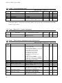
3.11. J-area (Digital communication option setting area)
Rewritable when in operation: Y = Yes N = No
Console
display
J-00
Set-up items
Digital communication
selection
Set-up range (item selection)
option
J-01
ASYC66-Z/CC66-Z option baud rate
J-02
OPCN66-Z option baud rate
J-03
J-04
J-05
J-06
PBUS66-Z slave address
OPCN66-Z option input
OPCN66-Z option output
(For future extension option)
J-07
ASYC66-Z/OPCN66-Z
transmission
selection/CC66-Z version selection
0: OFF
1: OPCN66-Z
2: ASYC66-Z
3: DNET66-Z
4: PBUS66-Z
5: IO66-Z
6: (For future extension option)*1
7: CC66-Z
(ASYC66-Z)
(CC66-Z)
0: 1200bps
0: 156kbps
1: 2400bps
1: 625kbps
2: 4800bps
2: 2.5Mbps
3: 9600bps
3: 5Mbps
4: 19200bps
4: 10Mbps
5: 38400bps
5: 10Mbps
0: 125kbps
1: 250kbps
2: 500kbps
3: 1Mbps
4: (For factory adjustment) *2
0 to 126
3 to 19
2 to 12
Please stay on the default value.
(ASYC66-Z)
0: 0ms
1: 5ms
2: 10ms
3: 20ms
4: 40ms
5: 60ms
6: 100ms
(OPCN66-Z)
Baud rate (J-02)[bps]
0:
1:
2:
3:
4:
5:
6:
(CC66-Z)
Version
0:
1:
2:
3:
4:
5:
6:
J-08
J-09
ASYC66-Z/PBUS66-Z
communication mode selection
DNET66-Z output instance number
setting
1.1
1.1
1.1
1.1
2.0(2×)
2.0(4×)
2.0(8×)
(ASYC66-Z)
125k
200µs
200µs
200µs
200µs
200µs
200µs
200µs
Default setting
Unit
Rewritable
0
―
N
4
―
Y
3
―
N
2
14
6
0
―
―
―
―
N
N
N
N
0
―
N
0
―
N
0
―
N
250k
200µs
200µs
200µs
200µs
150µs
100µs
100µs
Baud rate (J-02)[bps]
Exclusive
station
1
2
3
4
1
1
1
0:
1:
2:
3:
4:
5:
6:
500k
200µs
200µs
200µs
200µs
150µs
100µs
50µs
1M
200µs
200µs
200µs
200µs
150µs
100µs
50µs
(PBUS66-Z)
0: standard mode
0: PROFIDRIVE mode
1: Positioning mode 1 1: Factory original mode
2: positioning mode 2 2: Special mode
0: Instance No.20
1: Instance No.21
2 to 10: (Factory original communication mode)
27
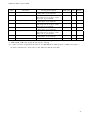
Induction motor vector mode
Console
display
J-10
J-11
J-12
J-13
J-14
J-15
Set-up items
Set-up range (item selection)
DNET66-Z input instance number
setting
DNET66-Z speed scale setting
DNET66-Z
monitor data number
setting
HighSpeed response input selection
Date/Time data selection from
communication
Connectied number of outside
DB(Dynamic
Brake) units with
communication
Default setting
Unit
Rewritable
0: Instance No.70
1: Instance No.71
2 to 15: (Factory original communication mode)
0
―
N
-126 to 127
0 to 119
3
3
―
―
N
Y
0: Communication
1: Analog input (2)(AIN2)
0: without date/time data
1: with date/time data
0 to 6
0
―
N
0
―
N
0
―
Y
*1: J-00=6 is for a future extension option. Under normal conditions, please do not use this setting.
*2: J-02=4 is for factory adjustment. Under normal conditions, please stay on the factory setting.
28
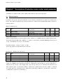
Induction motor vector mode
3.12. L-area (Input gain, output gain setting area)
Rewritable when in operation: Y = Yes N = No
Console
display
L-00
L-01
L-02
L-03
L-04
L-05
L-06
L-07
L-08
L-09
L-10
L-11
L-12
L-13
L-14
L-15
L-16
L-17
L-18
L-19
L-20
L-21*1
Set-up items
Vdc detection gain
Analog input(1) gain
Analog input(1) offset
Analog output(1) gain
Analog output(1) offset
Analog input(2) gain
Analog input(2) offset
Analog input(3) gain
Analog input(3) offset
Analog output(2) gain
Analog output(2) offset
Analog output(3) gain
Analog output(3) offset
Analog input(4) gain
Analog input(4) offset
Analog input(5) gain
Analog input(5) offset
Analog output(4) gain
Analog output(4) offset
Analog output(5) gain
Analog output(5) offset
Inverter operation mode monitor
Set-up range (item selection)
Default setting
80.0 to 120.0
50.00 to 150.00
-50.00 to 50.00
50.0 to 150.0
-50.0 to 50.0
50.00 to 150.00
-50.00 to 50.00
50.00 to 150.00
-50.00 to 50.00
50.0 to 150.0
-50.0 to 50.0
50.0 to 150.0
-50.0 to 50.0
50.00 to 150.00
-50.00 to 50.00
50.00 to 150.00
-50.00 to 50.00
50.0 to 150.0
-50.0 to 50.0
50.0 to 150.0
-50.0 to 50.0
SnPL (SIMPLE mode)
FuLL (FULL mode)
100.0
Adjusted
Adjusted
Adjusted
Adjusted
100.00
0.00
100.00
0.00
100.0
0.0
100.0
0.0
100.00
0.00
100.00
0.00
100.0
0.0
100.0
0.0
SnPL
Unit
Rewritable
%
%
%
%
%
%
%
%
%
%
%
%
%
%
%
%
%
%
%
%
%
―
N
Y
Y
Y
Y
Y
Y
Y
Y
Y
Y
Y
Y
Y
Y
Y
Y
Y
Y
Y
Y
N
*1: Inverter operation mode monitor (L-21) is available only for indication.
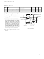
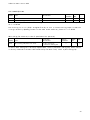
3.13. n-area (Monitor adjusting area)
Rewritable when in operation: Y = Yes N = No
Console
display
n-00
Inverter control mode
n-01
Capacity/Voltage class
Set-up items
Set-up range (item selection)
o: Induction motor V/f mode
V: Induction motor vector mode
E: ED motor vector mode
2r222 to 9022
2r244 to 31544
Default setting
Unit
Rewritable
o
―
N
Equivalent to
rating of
inverter
―
N
Note: n-area is available only for displaying contents of setting items.
Rewrite of contents can be done by rewriting of inverter mode, capacity or voltage class of S-area. For
the detail of S-area, please refer to Chapter3 3.16 S-area <Mode selection, analog input/output adjusting
area>, also chapter4 4.16 S-area <Mode selection, analog input/output adjusting area>.
29
Induction motor vector mode
3.14. o- area (Factory adjustment area)
Rewritable when in operation: Y = Yes N = No
Console
display
o-00
o-01
o-02
o-03
o-04 to
o-53
Set-up items
SpecialAdjustment
SpecialAdjustment
SpecialAdjustment
SpecialAdjustment
―
Set-up range (item selection)
0 to 65535
0 to 65535
0 to 65535
0 to 65535
These are for factory adjustment. Please
stay on the factory default value.
Default setting
―
―
―
―
―
Unit
Rewritable
―
―
―
―
―
Y
Y
Y
Y
―
Note: o-area is for factory adjusting and special purpose, so that cannot be changed. No indication is displayed
on the console monitor. Please stay on the factory default setting. (Error will be indicated if you attempt
to write in this area.)
3.15. P-area (Built-in PLC, P resistor setting area)
Rewritable when in operation: Y = Yes N = No
Console
display
P-00 to 99
Set-up items
P resister constant setting
Set-up range (item selection)
See separate booklet “User manual for
VF66series PC Tool”.
Default setting
―
Unit
Rewritable
―
―
3.16. S-area (Mode selection, analog input/output adjusting area)
Rewritable when in operation: Y = Yes N = No
Console
display
Set-up items
S-00
Special mode selection
S-01
S-02
S-03
S-04
Cumulative operation timer (1) clear
Cumulative operation timer (2) clear
Vdc adjustment
ROM rewrite enabling switch*2
S-05
S-06
―
Analog input (1) adjust
S-07
Analog output (1) adjust
S-08
Analog input (2) adjust
30
Set-up range (item selection)
1: Inverter initialization
2: Inverter mode change
3: Delete protection related
4: Switching between SIMPLE mode and FULL mode
10: FULL mode auto-tuning (forward)
11: FULL mode auto-tuning (reverse)
12: DC mode auto-tuning (forward)
13: DC mode auto-tuning (reverse)
99:Inverter initialization(For factory
adjustment) *1
101: Data transfer to SET66EX-Z
102: Data copy (exclude A-area) from SET66EX-Z)
103: Data copy (include A-area) from SET66EX-Z
104: Data comparison with SET66EX-Z
1: Clearing Timer (1)
1: Clearing Timer (2)
Vdc value (V): Vdc detect gain adjust
Rewriting of ROM will be possible by entering
“1040” after the power is on.
―
1: Analog input (1) offset adjustment
Input analog input (1) voltage (V) ×1000:
Analog input (1) gain adjustment
1: Analog output (1) offset adjustment
2: Analog output (1) gain adjustment
1: Analog input (2) offset adjustment
Input analog input (2) voltage (V) ×1000:
Analog input (2) gain adjustment
Default setting
Unit
Rewritable
―
―
Y
―
―
―
―
―
―
―
―
Y
Y
N
N
―
―
―
―
N
N
―
―
N
―
―
N
Induction motor vector mode
Console
display
Set-up items
S-09
Analog output (2) adjust
S-10
Analog input (3) adjust
S-11
Analog output (3) adjust
S-12
Analog input (4) adjust
S-13
Analog output (4) adjust
S-14
Analog input (5) adjust
S-15
Analog output (5) adjust
S-16
For factory adjustment
Set-up range (item selection)
1: Analog output (2) offset adjustment
2: Analog output (2) gain adjustment
1: Analog input (3) offset adjustment
Input analog input (3) voltage (V) ×1000:
Analog input (3) gain adjustment
1: Analog output (3) offset adjustment
2: Analog output (3) gain adjustment
1: Analog input (4) offset adjustment
Input analog input (4) voltage (V) ×1000:
Analog input (4) gain adjustment
1: Analog output (4) offset adjustment
2: Analog output (4) gain adjustment
1: Analog input (5) offset adjustment
Input analog input (5) voltage (V) ×1000:
Analog input (5) gain adjustment
1: Analog output (5) offset adjustment
2: Analog output (5) gain adjustment
Default setting
Unit
Rewritable
―
―
N
―
―
N
―
―
N
―
―
N
―
―
N
―
―
N
―
―
N
―
―
Y
Note: For the setting of S-area, first write “1040” followed by entering the function selection item within 60 second.
*1: Under normal conditions, please do not use this setting.
*2: In order to transfer the program of PLC function into ROM, ROM rewrite enabling switch is needed to be (S-04) = 1.
For detail of PLC function, please refer to <User manual for VF66 series PC Tool>.
31
Induction motor vector mode
Chapter4
Description of Induction motor vector mode parameter
Parameters for Induction motor vector mode are described for each item in each area.
4.1. Basic set-up area
In the basic set-up area, most often used basic set-up items for the operation of inverter are concentrated.
In this area, operation speed setting, normal acceleration / deceleration time adjustment and etc can be set
from the console.
Operation speed setting
Display
Items
0.SrEF
Speed command
1.FJoG
2.rJoG
Forward JOG speed
Reverse JOG speed
Set-up range
Set-up
Default
Unit
(Item selection)
resolution data
-Maximum speed (A-00) to Maximum
1
0 r/min
speed (A-00)
Minimum speed (A-01) to 300
1
24 r/min
-300 to −Minimum speed (A-01)
1
-24 r/min
Speed command (0.SrEF):
Operation speed can be set from the console. Select “Console” as a Command input place when coupled (b-09),
and so that effective when either “Coupled” or “console” is selected for the Speed commanding place selection
(b-10). See Chapter4 4.3 “b-area” for more detail.
Jog speed (forward / reverse) (1.FJoG / 2.rJoG):
Set-up Jog speed for forward and reverse rotations.
Acceleration / deceleration time set-up
Display
Items
3.Acc1
4.dEc1
5.Acc2
6.dEc2
Acceleration
Deceleration
Acceleration
Deceleration
time(1)
time(1)
time(2)
time(2)
Set-up range
(Item selection)
0.0 to 3600.0
0.0 to 3600.0
0.0 to 3600.0
0.0 to 3600.0
Set-up
resolution
0.1
0.1
0.1
0.1
Default
Unit
data
30.0
sec
30.0
sec
0.3
sec
0.3
sec
Set–up the acceleration time from 0 to the Maximum speed (A-00) and the deceleration time from the maximum
speed to 0. VF66B has four different acceleration / deceleration time settings (in case of acceleration /
deceleration (3) and (4), d-02 through d-05), each setting can be set or switched from outside by the
multi-function input. (In the factory default, acceleration / deceleration (1)(3.Acc1、4.dEc1) is selected
for normal operation, and acceleration / deceleration (2)(5.Acc2、6.dEc2) for Jog operation. Please refer
to Chapter4 4.5 <d-area> for more detail.)
32
Induction motor vector mode
Speed control gain set-up
Display
Items
7.ASrP
8.ASrI
9.ASrJ
Speed control integral time constant (1)
Speed control proportion gain(1)
Speed control system moment of inertia(1)
Set-up range
(Item selection)
3 to 50
20 to 10000
0 to 65535
Set-up
resolution
1
1
1
Default
Unit
data
―
15
40 msec
10
gm2
In the VF66B vector mode, speed control is achieved by MFC control which combines feed forward and cancelation
by using disturbance torque observer together.
Speed control proportion gain(1)(7.ASrP):
Set up the proportional gain of speed control.
Speed control integral time constant (1)(8.ASrI):
Integral gain equivalent to speed control is set at
filter time constant.
Speed control system moment of inertia(1)(9.ASrJ):
Set the moment of inertia used for cancelation of
speed control and feed forward in gm2. Normally,
20-100% of the combined value, the value inertial
moment of load converted on the motor shaft and
the inertial moment of motor itself, is input. If gear
noise is loud because of large backlash or vibration
in the belt system, then input smaller value or
inactivate cancelation and feed forward by the
ASR cancelation usage selection (i-14) and ASR
feed-forward usage selection (i-15) respectively.
ASR feed-forward
usage selection (i-15)
Js /(1+Tis)
Speed command
+
Kp
Speed control proportion gain(1)
7.ASrP
G(s)
Motor speed
Torque command
+
+
-
Moment of inertia
of the system
+
Speed control integral t ime constant
9.ASrJ
8.ASrI
Filter
-
+
ASR cancelation usage
selection (i-14)
Speed control block
*Please refer to Chapter4 4.10 “i-area” for more
information.
33
Induction motor vector mode
4.2. A-area
(Max.motor speed, motor rating, parameter set-up areas)
A-area is the set-up area for the motor parameter that is necessary for VF66B inverter to control the motor.
Please be sure to set parameters in accordance with specification of the motor or the system before the operation
of VF66B. Moreover, items A-11 through A-25 can be set automatically by automatic tuning. Combine the inverter
with the motor, and carry on an automatic tuning to set the data to items A-11 through A-25 before the practical
operation. Please refer to Chapter1 1.4 <Automatic tuning> for more detail of automatic tuning.
Maximum and minimum speed settings of motor
Display
Items
A-00
Maximum speed
A-01
Minimum speed
Set-up range
Set-up
(Item selection)
resolution
300 to 14700
1
(Depends on A-10 setting)*1 to
1
Maximum speed (A-00)
Default Unit
data
1800 r/min
12 r/min
*1: The minimum setting value for A-01 will be 12 when A-10=0, and 0 when A-10=1.
The Maximum speed (A-00) sets the maximum speed (absolute value) of the motor for operation. Inverter uses
this setting as 100% (reference) to control motor speed. Please set 1-4 times of the rated motor speed as the
maximum speed. In case if the motor is only used below the rated speed of the motor, then set the rated speed
as the maximum speed. (However, no value greater than the value equivalent to 400Hz (i.e. 12000 when 4-pole,
8000 when 6-pole) can be set.) The Minimum speed (A-01) sets the minimum speed of the motor for operation.
This is an absolute value for speed control so that even if the value smaller than the minimum speed is input,
it will be limited to the minimum speed. (However, when torque control mode is selected by the Operation mode
selection (i-07), this will be invalidated. For more information about Operation mode selection (i-07), please
refer to Chapter4 4.10 i-area.)
Setting of the indicated value on motor’s rating plate
Set-up
resolution
Default
data
Unit
Note 1
0.00
kW
0
V
0.00
A
Display
Items
Set-up range
(Item selection)
A-02
Rated motor capacity
(Min. value depends on inverter’s rating) to
rated capacity*1
A-03
Rated motor voltage
(200V class) 70 to 230
(400V class)140 to 460
A-04
Rated motor current
20-150% of inverter’s rated current
A-05
A-06
Rated motor speed
Number of motor pole
20-100% of the max. speed
1
2 to 12
―
A-07
Rated motor frequency
Rated motor speed×pole number/120 to
rated motor speed ×pole number/120+7.0
1
Note 1
0.1
0 r/min
4 Pole
0.0
Hz
*1:・Please see following table for the minimum value setting for the Rated motor capacity (A-02).
・If rated voltage of the motor is larger than 190V(200V class) / 380V(400V class), the maximum value of
the setting range will be proportionally larger.
Note 1: Varies depend on inverter type.
34
Induction motor vector mode
Minimum setting value for A-02
Inverter
type
Minimum setting
value for A-02
Inverter
type
Minimum setting
value for A-02
2R222
3R722
5R522
7R522
1122
1522
2222
3022
3722
4522
5522
7522
9022
15022
18022
0.75
1.10
1.50
2.20
3.70
5.50
7.50
11.00
15.00
22.0
30.0
37.0
2R244
3R744
5R544
7R544
1144
1544
2244
3044
3744
4544
5544
7544
11044
16044
20044
25044
0.75
1.10
1.50
2.20
3.70
5.50
7.50
11.00
15.00
22.0
30.0
37.0
45.0
55.0
75.0
110.0
31544
160.0
40044
200.0
50044
250.0
60044
315.0
75044
400.0
100044
500.0
45.0
55.0
75.0
Set the rated value stated in the rating plates or data sheets to items
A-02 through A-07. These settings are necessary for operation of the
motor or for automatic tuning and therefore they must be set prior to
automatic tuning. An example of a motor rating plate is shown in the right
figure.
If the motor has dual rating on its rated voltage and rated current,
set larger values to Rated motor voltage (A-03) and Rated motor current
(A-04) within the intended speed range.
If the motor is intended to use up to its base power output, then set
the base speed to the rated motor speed (A-05). It will be a constant
torque control area if the speed is below the preset rated motor speed
(A-05), and a constant power control area if the speed is above the preset
speed (A-05).
Input value in
the rating plate
rating plate
Motor rating plate
PG pulse number setting
Display
Item
Set-up range
(Item selection)
A-08
Number of PG-pulse
60 to 3600
Set-up
resolution
1
Default Unit
data
600 P/R
If PG is used as a speed sensor in Induction motor vector mode, set the pulse number of the PG which is directly
connected to the motor. Number of PG-pulse (A-08) is ignored when it is in a speed sensor-less vector control.
35
Induction motor vector mode
PWM carrier frequency setting
Display
Item
Set-up range
(Item selection)
A-09
PWM carrier frequency
1.0 to 6.0
Set-up
resolution
0.1
Default
data
6.0
Unit
kHz
The modulation carrier frequency of the inverter’s voltage output PWM.
In the Induction motor vector mode of VF66B, it is necessary to synchronize the cycle of torque control with
carrier frequency so that if carrier frequency is changed, then control characteristics will be changed.
Especially, if carrier frequency is set to below 2kHz, it slows torque control cycle and may adversely affect
on the control characteristics. Under normal conditions, please set it to 6.0kHz.
PG selection
Set-up
resolution
Display
Item
Set-up range
(Item selection)
A-10
PG selection
0: S-mode Sensor-less drive
1: V-mode with PG (AB phase input)
Default
data
Unit
0
―
―
In the PG selection (A-10), select presence or absence of PG. In the factory default setting, A-10=0 (S-mode
sensor-less drive without PG) is selected. An attached PG66 board or optional board is required for the drive
with PG. Please refer to the user manual for options for more information on optional circuit board.
Items set by automatic tuning (Dead time compensation for IGBT of the inverter, primary resistance of the motor)
* Following items are the data set by automatic tuning. Please refer to Chapter1 1.4 <Automatic tuning> for
more information.
Display
Items
A-11
A-12
A-13
A-14
A-15
A-16
DeadTime
DeadTime
DeadTime
DeadTime
DeadTime
DeadTime
Set-up range
(Item selection)
compensation
compensation
compensation
compensation
compensation
compensation
(U
(U
(V
(V
(W
(W
phase+side)
phase-side)
phase+side)
phase-side)
phase+side)
phase-side)
0.00
0.00
0.00
0.00
0.00
0.00
to
to
to
to
to
to
9.99
9.99
9.99
9.99
9.99
9.99
Set-up
resolution
0.01
0.01
0.01
0.01
0.01
0.01
Default
data
0.00
0.00
0.00
0.00
0.00
0.00
Unit
μsec
μsec
μsec
μsec
μsec
μsec
Set the dead time compensation of IGBT of each phase in the inverter to A-11 through A-16 in order to calculate
precise output voltage for control calculation. There are elements on the + and – sides of each U, V and W
phase so that there are six separate dead time compensations provided for six elements. In the Induction motor
vector mode, these values will be reset to 0 during initialization.
36
Induction motor vector mode
Electric constant of the motor
* Following items are the data set by automatic tuning. Please refer to Chapter1 1.4 “Automatic tuning” for
more information.
Set-up
resolution
Set-up range
(Item selection)
Display
Items
A-17
Motor primary resistance
A-18
Motor secondary resistance
A-19
Motor leakage inductance
A-20
Motor mutual inductance
A-21
A-22
A-23
A-24
A-25
Motor inductance saturation coefficient(1)
Motor inductance saturation coefficient(2)
(Setting range and
depend on inverter
(Setting range and
depend on inverter
(Setting range and
depend on inverter
(Setting range and
depend on inverter
Motor core loss torque compensation
Motor loss coefficient(1)
Motor loss coefficient(2)
0.0
0.0
0.0
0.0
0.0
to
to
to
to
to
Default
data
Unit
―
0.0*2
mΩ
―
0.0*2
mΩ
―
0.0*2
mH
―
0.0*2
mH
0.1
0.1
0.1
0.1
0.1
0.0
0.0
0.0
0.0
0.0
%
%
%
%
%
resolution differ
capacity) *1
resolution differ
capacity) *1
resolution differ
capacity) *1
resolution differ
capacity) *1
50.0
50.0
20.0
200.0
200.0
*1: Please refer to below table for the setting range of A-17 through A-20.
*2: For the initialization data for A-17 to A-20, the position of the decimal point will change depend on the
inverter capacity.
Setting range of A-17 to A-20
Inverter
type
A-17/A-18
setting range
A-19/A-20
setting range
Inverter
type
2R222
3R722
5R522
7R522
1122
1522
2222
3022
3722
4522
5522
7522
9022
1 to 65535
0.1 to 3276.7
2R244
3R744
5R544
7R544
1144
1544
2244
3044
3744
4544
5544
7544
11044
15022
18022
0.1 to 6553.5
0.01 to
655.35
0.001 to
65.535
0.01 to 327.67
0.001 to
32.767
16044
A-17/A-18
setting range
1 to 65535
A-19/A-20
setting range
0.1 to 3276.7
0.1 to 6553.5
0.01 to 327.67
0.01 to
655.35
20044
25044
31544
0.001 to
32.767
40044
50044
60044
0.001 to
65.535
75044
100044
37
Induction motor vector mode
・Set (Motor primary resistance) + (Wiring resistance between inverter and motor) to the Motor primary resistance
(A-17). Optimal value will be set by automatic tuning. This item is set by either FULL mode automatic tuning
or DC mode automatic tuning. In the Induction motor vector mode, precise values are required so that it
is necessary to carry on either of the automatic tuning to set the values.
* In case if wiring distance is changed considerably after the automatic tuning, please redo the automatic
tuning.
・For the Motor secondary resistance (A-18), set the primary side corresponding value of the secondary resistance
(= rotor resistance) of the motor. If automatic tuning is not possible and data is needed to be set manually
from the data sheet of the motor, please set the corresponding value at 25℃.
・Set the leakage inductance of the motor to the Motor leakage inductance(A-19). If automatic tuning is not
possible and data is needed to be set manually from the data sheet of the motor, set an average value of
primary side leakage inductance and secondary side leakage inductance (primary side corresponding value).
・Set the mutual inductance of the motor to the Motor mutual inductance (A-20). Inductance will be saturated
by flux, however, in this setting, set the inductance value at rated flux.
・Motor inductance saturation coefficient(1) (A-21) and Motor inductance saturation coefficient(2) (A-22)
are compensation coefficient to compensate saturation of mutual inductance. Set the rate of increase against
the Motor mutual inductance (A-20) in % when flux is 90% and 70% of the rated flux.
・For the Motor core loss torque compensation (A-23), set the compensation torque equivalent to core loss
in the motor.
・Motor loss coefficient(1) (A-24) and Motor loss coefficient (2) (A-25) are the coefficient indicating
electricity and mechanical loss measured by automatic tuning. These settings are not used for control so
that no need to set in the manual setting.
38
Induction motor vector mode
4.3. b-area (Operation mode, operation sequence setting area)
Setting data rewrite protection
Display
Items
Set-up range
(Item selection)
b-00
Setting data rewrite protection
OFF (Inactive)
ON (Activate protection)
Set-up
resolution
―
Default
data
Unit
OFF
―
When the Setting data rewrite protection (b-00) is turned ON, the data changed by SET66-Z or others will not
be accepted. If data change is needed, please turn-off the Setting data rewrite protection (b-00).
* Any attempt to rewriting data when b-00 is turned on will result in indication of
on the console
panel.
Stop mode selection
Display
Items
b-01
Stop mode selection
b-02
b-03
b-04
Stop speed
DC brake operation time
DC brake gain
b-05
JOG stop mode selection
b-06
JOG stop speed
Set-up range
(Item selection)
0: Free stop
1: Deceleration stop
2: Deceleration stop with DC brake
0 to 300
0.0 to 10.0
20.0 to 500.0(rated exciting current=100%)
0: Free stop
1: Deceleration stop
2: Deceleration stop with DC brake
0 to 300
Set-up
resolution
―
1
0.1
0.1
―
1
Default
data
Unit
1
―
30 r/min
0.0 sec
100.0
%
0
―
30 r/min
Stop mode selection (b-01) and JOG stop mode selection (b-05) set the operation selection when Operation command
/ Jog command is turned OFF. When other than 0 (Speed control) is selected for the Operation mode selection
(i-07) in the vector mode, the stop mode will be always free stop regardless of these settings. For more
information on i-07 <Operation mode selection>, please refer to Chapter4 4.10 “i-area”.
JOG stop speed (b-06) sets the stopping speed at Jogging.
39
Induction motor vector mode
Free stop
Deceleration stop
Deceleration stop with DC brake
Voltage output is stopped when Operation
command / Jog command is turned off.
Voltage output is stopped after
deceleration to the setting of the Stop
speed (b-02) / JOG stop speed (b-06) in
accordance with deceleration time.
DC brake is activated for the time set by
the DC brake operation time (b-03) after
deceleration to the setting of the Stop
speed (b-02) / JOG stop speed (b-06) in
accordance with deceleration time.
Electric current during DC brake is set
in the DC brake gain (b-04).
Operation /
Jog command
Operation /
Jog command
Operation /
Jog command
Output
Current
Output
Current
Output
Current
b-04
b-03
Free run
b-02/b-06
Motor Speed
Motor Speed
b-02/b-06
Motor Speed
Operation selection for Instantaneous power interruption restart
Display
Item
Set-up range
(Item selection)
b-07
Instantaneous power interruption restart
OFF (Inactive)
ON (Active)
Set-up
resolution
Default
data
Unit
OFF
―
―
Instantaneous power interruption is the period between fall of DC voltage (Vdc) to the voltage below the specified
value and recovery of the DC voltage to the voltage above the specified value without causing failure in control
power. In this area, select the process after the recovery of power when the operation is suspended due to
instantaneous power interruption.
OFF: In this setting, operation will not resumed even though power is recovered (inverter stays on stop). To
resume operation, it is necessary to turn-off the Operation command (Jog command) once, and then turn-on
the command again.
ON: In this setting, operation is automatically resumed after the recovery of the power. On condition that the
operation is commanded by the contact signal or by the digital communication option, the operation command
to the inverter must stay ON. Start-up jam protection (StrF) will be activated if the operation cannot resumed
with the operation command to the inverter is stayed ON, after the suspension of the operation.
Reverse prohibition mode selection
Display
b-08
Item
Set-up range
(Item selection)
Reverse prohibition mode selection
0: Normal
1: Prohibition of nonconforming
rotation against command
2: Reverse prohibition
Prohibits reverse rotation.
Normal (b-08=0):
40
Set-up
resolution
―
Default
data
Unit
0
―
Induction motor vector mode
This is normal operation. No limitation on both forward and reverse rotations.
Prohibition of nonconforming rotation against command (b-08=1):
Prohibits reverse rotation against the operation command at the inverter start-up. Once the motor is started,
it keeps prohibition against the reverse rotation to the operation command made at the time of inverter start-up
until the inverter is turned off. Even if the forward rotation command is switched to the reverse rotation
command after the start-up, the prohibition will not change unless otherwise the inverter is turned off.
Start at forward
Start at reverse
Rotation speed command to +
Forward operation
Reverse operation
Rotation speed command to −
Limit to +minimum speed
Limit to −minimum speed
Reverse rotation prohibition (b-08=2):
Regardless of the direction of the operation command, it prohibits reverse rotation of the motor (assuming
the direction of the rotation as forward rotation when the output voltage phase order of the inverter is U
→V→W). Speed command in reversed direction is limited to +minimum speed.
Command input place selection for speed, operation and Jog commands
Display
Items
b-09
Commanding place when coupled
b-10
Speed commanding place selection
b-11
Operation commanding place selection
b-12
JOG commanding place selection
Set-up range
(Item selection)
0:
1:
2:
0:
1:
2:
3:
4:
Terminal block
Console (SET66-Z)
Digital communication option
Coupled
Analog input(1)[terminal block](AIN1)
Console (SET66-Z)
Digital communication option
Analog input(2)[terminal block for
IO66-Z option or digital communication
option](AIN2)
5: (For extension option)*1
6: Analog input(3)[IO66-Z option terminal
block](AIN3)
7: Built-in PLC
0: Coupled
1: Terminal block
2: Console (SET66-Z)
3: Digital communication option
Set-up
resolution
Default
data
Unit
―
1
―
―
0
―
―
0
―
―
0
―
*1: b-10=5 is for a future extension option. Under normal conditions, please do not use this setting.
Select the commanding place of the speed command, the operation command and the Jog command. These input places
can be set as a batch by the setting of b-09 <Commanding place when coupled>. The input place for each command
by combination the setting b-09 through b-12 is as follows:
41
Induction motor vector mode
0: Terminal block
0: Coupled
1: Analog input(1)
[terminal block](AIN1)
2: Console (SET66-Z)
Speed
command
(b-10)
3: Digital communication option
4: Analog input(2)
[ option](AIN2)
5: (For extension option)*1
6: Analog input(3)
[option](AIN3)
7: Built-in PLC
0: Coupled
Operation
command
(b-11)
1: Terminal block
2: Console (SET66-Z)
3: Digital communication option
0: Coupled
Jog
command
(b-12)
1: Terminal block
2: Console (SET66-Z)
3: Digital communication option
Commanding place when coupled (b-09)
1: Console
2: Digital communication option
VFC66-Z P board
[AIN1] terminal
VFC66-Z P board
[AIN1] terminal
[0.SrEF] setting
[0.SrEF] setting
VFC66-Z P board
[AIN1] terminal
[0.SrEF] setting
Speed command by
communication
VFC66-Z P board
[AIN1] terminal
[0.SrEF] setting
Command by
communication
Command by
communication
Command by
communication
IO66-Z option, etc.
IO66-Z option, etc.
IO66-Z option, etc.
-
-
-
IO66-Z option
IO66-Z option
IO66-Z option
Built-in PLC
VFC66-Z P board
・[ST-F] terminal
・Set Multi-function input
terminal as operation
command [reverse]
VFC66-Z P board
・[ST-F] terminal
・Set Multi-function input
terminal as operation
command [reverse]
Console key
[START],[FOR/REV]
Operation command by
communication
VFC66-Z P board
Set Multi-function input
terminal as Jog command
[forward], [reverse]
VFC66-Z P board
Set Multi-function input
terminal as Jog command
[forward], [reverse]
Console key
[JOG/→], [FOR/REV]
Jog
command
by
communication
Built-in PLC
Console key
[START], [FOR/REV]
Built-in PLC
Operation command
communication
VFC66-Z P board
・[ST-F] terminal
・Set Multi-function input
terminal as operation
command [reverse]
Console key
[START], [FOR/REV]
Operation command by
communication
Console key
[JOG/→], [FOR/REV]
VFC66-Z P board
・[ST-F] terminal
・ Set Multi-function input
terminal as operation
command [reverse]
Console key
[START], [FOR/REV]
Operation command by
communication
Jog
command
by
communication
VFC66-Z P board
Set Multi-function input
terminal as Jog command
[forward], [reverse]
Console key
[JOG/→], [FOR/REV]
Jog
command
by
communication
VFC66-Z P board
Set Multi-function input
terminal as Jog command
[forward], [reverse]
Console key
[JOG/→], [FOR/REV]
command
by
Jog
communication
*1: b-10=5 is for a future extension option. Under normal conditions, please do not use this setting.
When the terminal block is selected as a speed commanding place, switching of the input characteristic (selection
of Voltage input 0 to ±10V, Voltage input 0 to +10V or Current input 4 to 20mA) should be done by b-17 <Analog
speed command characteristic selection>. In the factory default, Voltage input of 0 to +10V is selected.
42
by
Induction motor vector mode
Torque limiter setting
Display
Items
b-13
Forward powering torque limit
b-14
Forward regenerative torque limit
b-15
Reverse powering torque limit
b-16
Reverse regenerative torque limit
Set-up
resolution
Set-up range
(Item selection)
0 to the value depend on
motor current (A-04)*
- the value depend on Rated
current (A-04) to 0*
- the value depend on Rated
current (A-04) to 0*
0 to the value depend on
motor current (A-04)*
Rated
motor
motor
Rated
Default
data
Unit
1
150
%
1
-150
%
1
-150
%
1
150
%
Torque limit for powering and regenerative can be set in both forward and reverse rotations separately. If a
torque command exceeds this setting, then torque will be limited to this setting value.
* The maximum (minimum) value for torque limit will be 200×(rated current of inverter) / the value calculated
from Rated motor current (A-04). However, in case if calculated value exceeds 200%, then the maximum (minimum)
value will be 200%.
Characteristic setting of the analog speed command (VFC66-Z AIN1 terminal block)
Display
Items
Set-up range
(Item selection)
b-17
Analog speed command characteristic
selection
0: 0 to ±10V (bipolar)
1: 0 to 10V (monopolar)
2: 4 to 20mA
b-18
Analog speed command upper limit speed
b-19
Analog speed command lower limit speed
Absolute value of Analog speed command lower
limit speed (b-19) to 100.0
-Analog speed command upper limit speed
(b-18) to Analog speed command upper limit
speed (b-18)
Set-up
resolution
Default
data
Unit
―
1
―
0.1
100.0
%
0.1
0.0
%
Note: Analog speed command upper limit speed (b-18) and Analog speed command lower limit speed (b-19) are set in % with
respect to the Maximum speed (A-00).
(For the speed commanding place selection, please refer to b-09 < Commanding place when coupled> and b-10
< Speed commanding place selection>.)
For b-17 < Analog speed command characteristics selection>, select the speed command input of either voltage input
(bipolar or monopolar) or current input.
Note: When the Analog speed command characteristic selection (b-17) = 2(4 - 20mA input) is selected, please turn-on
the SW1 of the VFC66-Z P-board. When the Analog speed command characteristic selection (b-17) = 0 or 1, please
turn-off the SW1.
For the location of SW1, please refer to Chapter4 4.16 S-area for adjustment of Analog input(1) gain
(L-01) when the input characteristic is 4 to 20mA.
43
Induction motor vector mode
In case when the Analog input (1) terminal AIN1 is used for the speed input of the VF66B
The characteristic of the speed command input by the Analog input (1) is explained below.
1) Voltage input (0 to ±10V)(b-17=0)
In Analog speed command characteristics selection b-17=0, rotation of the motor can be reversed by inputting negative
voltage for the input voltage command. (In case if operation is made by reverse operation command, then the
rotation will be reversed by inputting positive voltage and forward by inputting negative voltage). Analog
commanding characteristic will be the setting of the Analog speed command upper limit speed (b-18) when inputting
+10V, and the negative value of the Analog speed command upper limit speed (b-18) when inputting -10V. However,
the negative side will be limited by the setting of the Analog speed command lower limit speed (b-19) and therefore
in order to use the maximum in negative side, it is needed to set -100% in the Analog speed command lower limit
speed (b-19). When the Minimum speed (A-01) is other than 0, it is limited so that the absolute value will not
be less than this speed. In this case, the characteristic when passing around 0V will be the hysteresis
characteristic as shown in figure below. (Speed at the start will be minimum speed in both directions; forward
if started with forward operation, and reverse if started with reverse operation.)
Speed command
Speed command
b-18
A-01
-10V
0
+10V
Input voltage
Input voltage
A-01×(-1)
b-19
b-18×(-1)
1-1) Voltage input when (0 to ±10V)
1-2) Minimum speed (A-01) hysteresis characteristic around 0
V
2) Voltage input (0 to 10V) (b-17=1)
Analog commanding characteristic will be the setting of the Analog speed command lower limit speed (b-19) when
inputting 0V, and the setting of the Analog speed command upper limit speed (b-18) when inputting 10V. However,
this is only effective in the positive voltage; negative side will be limited to the setting of the Analog speed
command lower limit speed (b-19) or 0 in the case when negative value is selected for the Analog speed command lower
limit speed (b-19).
When the Minimum speed (A-01) is other than 0, it is limited so that the absolute value will not be less than
this speed. As a speed command, it is for forward rotation only and should use reverse operation command for
reverse rotation.
44
Induction motor vector mode
Speed command
Speed command
b-18
b-18
b-19
0V
0V
10V
10V
b-19
Input voltage
Input voltage
2-2) 0 to 10V (when b-19 is less than 0)
2-1) 0 to 10V (when b-19 is 0 or more)
3) Current input (4 to 20mA) (b-17=2)
In Analog speed command characteristics selection b-17=2, the characteristic will be setting of the Analog speed command
lower limit speed (b-19) when inputting 4mA and setting of the Analog speed command upper limit speed (b-18) when
inputting 20mA. However, this is only effective in the positive current, negative side will be limited to the
setting of the Analog speed command lower limit speed (b-19) or 0 in the case when negative value is selected for
the Analog speed command lower limit speed (b-19).
When the Minimum speed (A-01) is other than 0, it is limited so that the absolute value will not be less than
this speed. As a speed command, it is for forward rotation only and should use reverse operation command for
reverse rotation.
Speed command
Speed command
b-18
b-18
b-19
4mA
4mA
20mA
20mA
b-19
Input current
3-1) 4 to 20mA (when b-19 is 0 or more)
Input current
3-2) 4 to 20mA (when b-19 is less than 0)
Analog input 0 limit function setting
Display
Item
Set-up range
(Item selection)
b-20
Analog input ZeroLimit voltage
0.000 to 1.000
Set-up
resolution
0.001
Default Unit
data
0.000
V
This function forcibly turns the command to 0 when the absolute value of the command input voltage input in
the Analog input (1) [AIN1] on the VFC66-Z P board is equal to or less than the value of this setting. This
function can be used when 0 setting cannot be obtained even though 0v is set due to the causes such as drift
in analog circuit. This function is effective in both speed command and torque command.
45
Induction motor vector mode
Analog output (1) characteristic selection (VFC66-Z AOT1 terminal block)
Display
b-21
Items
Set-up range
(Item selection)
Analog output(1) characteristic selection
0: Output voltage
1: Output current
2: Torque command
3: Speed
4: Speed command
5: Built-in PLC output
6: Calibration
7: Internal monitor
-1: 6F frequency*1
-2: 6F speed*1
-3: 6F calibration*1
Set-up
resolution
Default
data
Unit
1
―
―
Select analog output data output to the location between the terminal blocks [AOT1] and [GND1] on the VFC66-Z
P board.
*1: 6F means six times (6X) of the frequency signal. If “6F speed” (b-21=-2) or “6F calibration” (b-21=-3) is
selected, then the sixfold signal of the frequency corresponding value is output. Gain or offset value of
the 6F output may not be adjusted.
Analog output selected by the Analog output (1) characteristic selection (b-21)
0
Items
Output voltage
1
2
3
Output current
Torque command
Speed
Output voltage
7.5V / 200V (200V class)
7.5V / 400V (400V class)
5V / Inverter rated current
5V / 100%
10V / Maximum speed (A-00)
4
5
6
7
Items
Rotation speed command
(After accel/decel control)
Built-in PLC output
Calibration
Internal monitor
Output voltage
10V / Max. rotation speed
(A-00)
5V / 20000 (100%)*
Output 5V
―
* Please refer to the function manual of Control Block Editor for more detail.
6F output selected by the Analog output (1) characteristic selection (b-21)
-1
-2
-3
Items
6F frequency
6F speed
6F calibration
6F Output
Outputs sixfold frequency signal of the output frequency.
Outputs sixfold frequency signal of the corresponding value of speed.
Outputs sixfold frequency signal of the Maximum speed (A-00)
equivalent.
Note: In order to output 6F output with the Analog output (1) characteristic, switch the SW2, shown in below
figure, into “1” (Console panel side).
46
Induction motor vector mode
<Terminal>
2 1
SW2
SW1
CN-SI
SET66-Z
CN-SO
VFC66-Z
SW2
・In case motor speed (b-21=-2) is selected:
As shown in figure below, 6F signal (sixfold frequency signal of the frequency corresponding value) is output
from the terminal block [AOT1]-[GND1].
When motor speed is selected, the frequency corresponding value F will be :
F = (motor speed)/60×(number of motor pole)/2(Hz)
・In case calibration (b-21=-3) is selected:
Sixfold frequency signal of the value equivalent to the Maximum speed (A-00) is output. If digital counter
type frequency/revolution indicator is used, set the pulse count in 1/6 circle. In case if DC voltmeter
is used, the characteristic will be the average of 6F signal output as shown in figure below, so that adjust
it accordingly. (Note: when the frequency corresponding value at the maximum speed F exceeds 120Hz, use
the 1/2 of the value and when F exceeds 240Hz, then use the 1/4 of the value.)
10V
Approx.
10V
T1
T2
6F signal output waveform
(Max. output current is 5mA)
Frequency−Voltage characteristic
(When F is 120Hz or less)
T1 and T2 in the figure are:
T1=1msec
(Frequency corresponding value at the maximum speed F is 120Hz or less)
=0.5msec (Frequency corresponding value at the maximum speed F is 240Hz or less)
=0.25msec(Frequency corresponding value at the maximum speed F exceeds 240Hz)
T2=1/(6×F) F: output frequency or frequency corresponding value
47
Induction motor vector mode
4.4. c-area (Multi-function input related setting area)
Input signal setting for the multi-function input
Display
c-00
c-01
c-02
c-03
c-04
c-05
c-06
c-07
c-08
c-09
c-10
c-11
c-12
c-13
c-14
c-15
c-16
c-17
Set-up range
(Item selection)
Items
Multifunction input place selection
Multifunction
selection
Multifunction
selection
Multifunction
selection
Multifunction
selection
Multifunction
selection
Multifunction
selection
Multifunction
selection
Multifunction
selection
Multifunction
selection
Multifunction
selection
Multifunction
selection
Multifunction
selection
Multifunction
selection
Multifunction
selection
Multifunction
selection
Multifunction
selection
Multifunction
selection
0: Terminal block
1: Digital communication option
input
terminal(1)
function
input
terminal(2)
function
input
terminal(3)
function
input
terminal(4)
function
input
terminal(5)
function
input
terminal(6)
function
input
terminal(7)
function
input
terminal(8)
function
input
terminal(9)
function
input
terminal(10)
function
input
terminal(11)
function
input
terminal(12)
function
input
terminal(13)
function
input
terminal(14)
function
input
terminal(15)
function
input
terminal(16)
function
input
terminal(17)
function
Set-up
resolution
―
―
0: Preset speed selection 1
1: Preset speed selection 2
2: Preset speed selection 3
3: Accel./decel. time selection 1
4: Accel./decel. time selection 2
5: Speed up command (MRH mode)
6: Speed down command (MRH mode)
7: Speed hold
8: S-pattern accel./decel. prohibition
9: Max. speed reduction
10: Droop control disabled
11: Speed/torque control selection
12: Forward/reverse operation command selection
13: DC brake command
14: Initial excitation command
15: External failure signal 1
(protection relay 86A enabled)
16: External failure signal 2
(protection relay 86A enabled)
17: External failure signal 3
(protection relay 86A enabled)
18: External failure signal 4
(protection relay 86A enabled)
19: External failure signal 1
(protection relay 86A disabled)
20: External failure signal 2
(protection relay 86A disabled)
21: External failure signal 3
(protection relay 86A disabled)
22: External failure signal 4
(protection relay 86A disabled)
23: Trace back external trigger
24: 2nd set-up block selection
25: Emergency stop (B contact)
26: No function
27: Speed commanding terminal block selection
28: No function
29: Operation command [reverse] (STARTR)
30: Jog command [forward] (JOGF)
31: Jog command [reverse] (JOGR)
32: Emergency stop (A contact)
33: Protection reset (RESET)
34: External signal input 1
35: External signal input 2
36: External signal input 3
37: External signal input 4
―
―
―
―
―
―
―
―
―
―
―
―
―
―
―
―
Default Unit
data
0
29
30
31
32
33
0
1
2
3
4
5
6
7
8
9
10
11
―
―
―
―
―
―
―
―
―
―
―
―
―
―
―
―
―
―
・Multi-function input terminals (1) – (5) are terminal blocks of [MI1] – [MI5] of the VFC66-Z respectively. Terminal blocks
[MI6] – [MI17] of the Multi-function input terminals (6) – (17) are optional.
48
Induction motor vector mode
・When the Multifunction input place selection (c-00) is set to 1[Digital communication option], and when the setting values
of the multifunction input terminal function selection (c-01) – (c-17) are set to 0 (Preset speed selection 1) to 27 (Speed
commanding terminal block selection), then motor will be controlled by the signal from the digital communication option.
Therefore, functions of items 29 (Operation command [reverse]) to 33 (Protection reset) will be ineffective from the terminal
block.
Note: If PLCL function usage selection (i-00) is turned ON, above settings are ignored and the Multi-function
input terminal (1) – (5) (terminal blocks [MI1] – [MI5]) on the VFC66-Z P board and the Multi-function
input terminal (6) – (17) (terminal blocks [MI6] – [MI17]) on the optional board will be the terminal for
the input relay for the built-in PLC function. In this case, each function of the multi-function input
will be controlled by the built-in PLC function. Moreover, if the PLCL function usage selection (i-00)
is turned OFF and the PLCH function usage selection (i-01) is turned ON, then the Multi-function input
terminal (4) ([MI4] terminal block) will be set to 32 (Emergency stop (A contact)) regardless of the setting
of the Multi-function input terminal (4) function selection (c-04).
Connection of Multi-function input terminal (1) – (5)
PS
TB1
VFC66-Z
Internal power
(12V)
PS
CN-SI
4.7kΩ
Multi-function
input 1
Multi-function
input 2
Multi-function
input 3
Multi-function
input 4
Multi-function
input 5
TB1
VFC66-Z
CN-SI
4.7kΩ
MI1
Multi -fun cti on
inp ut 1
4.7kΩ
MI2
Multi -fun cti o n
inp ut 2
4.7kΩ
MI3
Multi -fun cti o n
inp ut 3
4.7kΩ
MI4
Multi -f un cti on
inp ut 4
4.7kΩ
MI5
Multi -f un cti on
inp ut 5
CN-SO
G
MI1
4.7kΩ
MI2
4.7kΩ
MI3
4.7kΩ
MI4
4.7kΩ
MI5
CN-SO
G
External power
(+12∼ +24V)
1.Source mode (with internal power source)
PS
TB1
Internal power
(12V)
VFC66-Z
CN-SI
2.Source mode (with external power source)
Exte rnal p owe r
(+12∼ +24V)
PS
4.7kΩ
Multi-function
input 1
Multi-function
input 2
Multi-function
input 3
Multi-function
input 4
Multi-function
input 5
VFC66-Z
CN-SI
4.7kΩ
MI1
Multi - fun cti on
inp ut 1
4.7kΩ
MI2
Multi -fun cti o n
inp ut 2
4.7kΩ
MI3
Multi -fun cti o n
inp ut 3
4.7kΩ
MI4
Multi -fun cti o n
inp ut 4
4.7kΩ
MI5
TB1
CN-SO
G
Multi -fun cti o n
inp ut 5
MI1
4.7kΩ
MI2
4.7kΩ
MI3
4.7kΩ
MI4
4.7kΩ
MI5
CN-SO
G
3.Sink mode (with internal power source)
4.Sink mode (with external power source)
Above figures are showing typical connection of the multi-function input signal. The maximum allowable voltage
is 24V and the maximum allowable current per terminal is 3mA.
Selection of either SOURCE mode or SINK mode is available for multi-function input signal, and either internal
power source of the inverter or external power source can be selected for each mode. In the factory default,
it is set to SOURCE mode. Switching between SOURCE mode and SINK mode can be done by changing jumper socket
of the VFC66-Z board.
49
Induction motor vector mode
CAUTION
z
z
[For your safety]
Please make sure to turn-off the inverter before connecting terminals
There is risk of electric shock.
Please close the front cover before turning on the inverter to avoid risk of electric shock.
<Terminal>
CN-SI
SET66-Z
CN-SO
VFC66-Z
Jumper pins
<Use of [CN-SO] jumper socket with internal power source>
Install a switch between the Multi-function terminals (1) – (5) (Terminals [MI1] - [MI5]) and [PS] terminal
to turn ON/OFF.
<Use of [CN-SI] jumper socket with internal power source>
Install a switch between the Multi-function terminals (1) – (5) (Terminals [MI1] - [MI5]) and [GND1] terminal
to turn ON/OFF.
Detail of multi-function input setting
No.
0 to 2
Items
Preset speed
Description
By selecting one of three input of the preset speed selection 1 - 3, you can utilize
the setting of the preset speed command 1 - 7 (d-15 - d-21).
Preset
speed 3
OFF
OFF
OFF
OFF
ON
ON
ON
ON
50
Preset
speed 2
OFF
OFF
ON
ON
OFF
OFF
ON
ON
Preset
speed 1
OFF
ON
OFF
ON
OFF
ON
OFF
ON
Speed command
Standard selection
d-15 (preset speed
d-16 (preset speed
d-17 (preset speed
d-18 (preset speed
d-19 (preset speed
d-20 (preset speed
d-21 (preset speed
(no preset)
command 1)
command 2)
command 3)
command 4)
command 5)
command 6)
command 7)
Induction motor vector mode
No.
3 and 4
Items
Acceleration /
deceleration time
selection
Description
Acceleration/deceleration time can be changed during operation by using the input of the
Acceleration/deceleration time selection 1 - 2.
(When S-pattern acceleration/deceleration is used, the S-pattern acceleration/deceleration usage
selection (d-06) is needed to be turned ON.)
Accel./decel. Accel./decel. Acceleration/deceleration time to be selected.
time select 2 time select 1 (Includes S-pattern accel./decel.)
OFF
OFF
Standard (Accel./Decel. time selected in d-00)
OFF
ON
Accel./Decel. time (2) (5.Acc2, 6.dEc2 and d-11 to 14)
ON
OFF
Accel./Decel. time (3) (d-02, d-03 (w/o S-pattern))
ON
ON
Accel./Decel. time (4) (d-04, d-05 (w/o S-pattern))
5 and 6
Speed UP/DOWN command
(MRH mode)
By turning the MRH function usage
selection (d-27) ON and selecting
terminal block for the speed
commanding
place,
acceleration/deceleration
by
UP/DOWN command becomes possible.
If speed exceeds its upper or lower
limit, it will be automatically
accelerated/decelerated to the
upper or lower limit without
having UP/DOWN command. Rotation
can be reversed by setting
negative value into the lower
limit speed.
When this signal is turned on
during acceleration/deceleration
operation of the inverter, the
inverter
temporarily
stops
acceleration/deceleration
and
hold the speed at that time.
When the signal is turned off, the
inverter
resumes
acceleration/deceleration.
(Note: speed hold is ineffective
during deceleration stop by the
stop command)
7
8
9
Speed hold
S-pattern
accel./decel.
prohibition
Maximum speed
reduction
10
Droop control disabled
11
Speed/torque
selection
control
Operation command
UP command
DOWN command
MRH upper limit
MRH lower limit
Motor
Speed
Operation command
Speed hold
Rotation speed
setting
Motor speed
S-pattern accel./decel. can be forcibly prohibited to obtain normal accel./decel. by turning on
this signal even when S-pattern accel./decel. usage selection is turned on and during the S-pattern
accel./decel. operation.
If terminal block is selected as the speed command
input place, the speed command will be reduced in Motor speed
b-18 Analog setting upper limit
accordance with the setting of the Maximum speed
Maximum speed
reduction rate (H-12) by turning on this signal (see
Reduction
When reduction is on
figure on the right).
rate
This signal can be turned ON/OFF when the motor is
stopped. If this signal is turned ON/OFF when the
motor is in operation, switching will not occurred
until the motor is stopped once.
Speed setting
10V
(This function is only effective for the analog
input from the terminal block)
Even when the Droop control usage selection (i-02) is turned ON, droop control will be disabled
by turning on this signal. For more information about droop control, please refer to Chapter3
3.10 <i-area> also Chapter4 4.10 <i-area>.
If the Operation mode selection (i-07) is set to 4 (Speed/torque control contact switch), switching
between speed control and torque control can be made by this signal. It will be speed control
at tuning OFF and torque control at tuning ON. For more information, please refer to Chapter3
3.10 <i-area> also Chapter4 4.10 <i-area>.
51
Induction motor vector mode
No.
12
Items
Forward/reverse
operation command
13
DC brake command
14
Initial
command
excitation
15 to 18
External failure
signal
(protection relay 86A
enabled)
19 to 22
External failure
signal
(protection relay 86A
disabled)
Trace back external
trigger
23
24
2nd
set-up
selection
block
Description
When the Operation commanding place selection (b-11) is set to 1 (terminal block) or the JOG
commanding place selection (b-12) is set to 1 (terminal block), the Operation command/Jog command
can be switched between forward and reverse by turning ON this signal. (forward → reverse or
reverse → forward)
* Because of the Operation commanding place selection (b-11) is set to 1, please install a switch
between[ST-F] terminal and [PS] terminal of the VFC66-Z terminal block in order to turn ON/OFF
the operation signal. For more information, please refer to the manual <Basic operation>.
Turning ON of this signal activates DC brake which allows DC current to flow into the motor. The
current can be adjusted by the DC brake gain (b-04) in the vector mode. After this signal is turned
OFF, the motor will be stopped after the duration set in the DC brake operation time (b-03).If
this signal and Operation/Jog command are input simultaneously, then Operation/Jog command will
be prioritized.
Turning ON of this signal activates the initial excitation operation which allows an exciting
current to flow into the motor. It can be used when pre-excitation is needed for quick response
at the start. There are two modes in initial excitation operation; AC initial excitation and DC
initial excitation. They can be selected by the Initial excitation selection (i-18).
Having a failure signal of peripheral equipment as an input of this signal, the inverter can be
stopped for protection.
When the external failure signal 1 – 4 is turned ON, then inverter cuts its output and turns ON
the protection relay 86A.
Simultaneously, [EF1] – [EF4] will appear on the console. Moreover, the trace back will be triggered
by this signal. To cancel the protective operation, execute protective operation reset by pressing
[STOP/RESET] key or by setting any of the multi-function input terminal to “protection reset” and
then turn it ON.
Same as above except the protection relay 86A will be ineffective. Also trace back will not be
triggered by this signal. In this case, if all of the Operation/Jog/DC brake commands of the
inverter are turned OFF, then protective operation will be released automatically.
Normally, trace back is triggered when failure is occurred or when protective operation is
activated, however, by inputting this signal, trace back can be triggered forcibly. For more
information about trace back, please refer to Chapter3 3.7 <F-area> also Chapter4 4.7 <F-area>.
When this signal is ON, each parameter set in the 2nd set-up block will be used.
ON
Parameter set at the
Parameter set at the
1st set-up block
2nd set-up block
OFF
25
Emergency stop
(B contact)
27
Speed commanding
terminal block
selection
29
30
31
52
Operation command
[reverse] (STARTR)
Jog command
[forward](JOGF)
Jog command [reverse]
(JOGR)
Emergency stop signal on the B contact input makes the contact open and brings an emergency stop.
(Therefore, care must be taken if this function is set into any of the terminal block, it makes
emergency stop and cannot be operated unless otherwise close the contact.)
Turning ON of this signal forcibly selects the terminal block (VFC66-Z[AIN1] terminal) as the
speed command input place regardless of the setting of the Speed commanding place selection (b-10).
If this signal and Preset speed selection are input simultaneously, then this signal will be
prioritized.
* If IO66-Z option or digital communication option is installed, it will be forcibly changed from
the VFC66-Z [AIN1] terminal to the terminal block [AIN2] terminal for the IO66-Z option or the
digital communication option regardless of the setting of the Digital communication option
selection (J-00).
Note: When the Digital communication option selection (J-00) is set to 0 (OFF), protective
function of the IO66-Z option or the digital communication option will not be activated.
With the setting of the Operation commanding place selection (b-11) = 1(terminal block), the cmotor
will be reversed when this signal is ON.
With the setting of the JOG commanding place selection (b-12) = 1(terminal block), it becomes
Jog operation [forward] when this signal is ON.
With the setting of the JOG commanding place selection (b-12) = 1(terminal block), it becomes
Jog operation [reverse] when this signal is ON.
Induction motor vector mode
No.
32
33
34 to 37
Items
Emergency stop
(A contact)
Protection reset
(RESET)
External signal input
Description
Emergency stop signal on the A contact input makes the contact open and brings an emergency stop.
Turning ON of this signal cancels the protective operation.
According to using this function, VFC can transmit the signal from peripheral devices to another
unit(master unit) through the optional digital communication board. (It is possible to use this
function as a coil input of PLC.)
4.5. d-area (Acceleration/deceleration time, speed jump function, MRH function selection area)
Selection and setting of acceleration/deceleration time
Items
d-00
Acceleration/Deceleration time selection
d-01
d-02
d-03
d-04
d-05
d-06
d-07
d-08
d-09
d-10
d-11
d-12
d-13
d-14
Set-up
resolution
Set-up range
(Item selection)
Display
JOG
acceleration/deceleration
selection
Acceleration time(3)
time
0: Acceleration/deceleration Time (1)
1: Acceleration/deceleration Time (2)
2: Acceleration/deceleration Time (3)
3: Acceleration/deceleration Time (4)
0.0 to 3600.0
Deceleration time(3)
0.0 to 3600.0
Acceleration time(4)
0.0 to 3600.0
Deceleration time(4)
0.0 to 3600.0
S-pattern acceleration/deceleration
usage selection
S-pattern rise time(1)
OFF (not use)
ON (use)
0.0 to 60.0
S-pattern acceleration reach time(1)
0.0 to 60.0
S-pattern fall time(1)
0.0 to 60.0
S-pattern deceleration reach time(1)
0.0 to 60.0
S-pattern rise time(2)
0.0 to 60.0
S-pattern acceleration reach time(2)
0.0 to 60.0
S-pattern fall time(2)
0.0 to 60.0
S-pattern deceleration reach time(2)
0.0 to 60.0
Default
data
―
0
―
1
Unit
―
―
0.1
0.1
0.1
0.1
30.0
30.0
30.0
30.0
sec
sec
sec
sec
―
OFF
―
0.1
0.1
0.1
0.1
0.1
0.1
0.1
0.1
0.1
0.1
0.1
0.1
0.1
0.1
0.1
0.1
sec
sec
sec
sec
sec
sec
sec
sec
Select an acceleration/deceleration time setting to be used in normal operation and Jog operation by the
Acceleration/Deceleration time selection (d-00) and JOG acceleration/deceleration time selection (d-01) respectively.
Please note that the acceleration/deceleration time setting for normal operation can be changed also from the
multi-function input.
Setting of d-00 or
d-01, or selection
from multi-function
input
0:Accel/Decel
time (1)
1:Accel/Decel
time (2)
2:Accel/Decel
time (3)
3:Accel/Decel
time (4)
Acceleration
time
Deceleration
time
S-pattern
rise time
S-pattern accel.
reach time
S-pattern
fall time
S-pattern decel.
reach time
3.Acc1
4.dEc1
d-07
d-08
d-09
d-10
5.Acc2
6.dEc2
d-11
d-12
d-13
d-14
d-02
d-03
0.0
0.0
0.0
0.0
d-04
d-05
0.0
0.0
0.0
0.0
・Acceleration time(1) (3.Acc1), Deceleration time(2) (4.dEc1), Acceleration time(2) (5.Acc2) and Deceleration
53
Induction motor vector mode
time(2) are items of the basic set-up area.
・When acceleration/deceleration time (3) or (4) is selected, all of the S-pattern acceleration/deceleration
time will be 0.0. Acceleration/deceleration time is acceleration/deceleration time between 0 speed and the
maximum speed of the setting and the time for S-pattern curve as shown in the figure below. To use S-pattern
acceleration/deceleration function, it is necessary to turn ON the S-pattern acceleration/deceleration usage
selection (d-06). When the selection (d-06) is OFF, S-pattern acceleration/deceleration cannot be obtained
even if time setting for the S-pattern acceleration/deceleration is set.
S-pattern acceleration reach time (d-8 and 12)
S-pattern fall time (d-9 and 13)
Maximum speed (A-00)
S-pattern rise time (d-07 and 11)
Accel. time (3.Acc1 and 5.Acc2)
S-pattern deceleration reach time (d-10 and 14)
Decel. time (4.dEc1 and 6.dEc2)
Time chart of acceleration/deceleration (S-pattern accel./decel.)
Preset operation speed command setting
Display
Items
d-15
d-16
d-17
d-18
d-19
d-20
d-21
Preset speed(1)
Set-up range
(Item selection)
Preset speed(2)
Preset speed(3)
Preset speed(4)
Preset speed(5)
Preset speed(6)
Preset speed(7)
-Maximum speed (A-00)
to Maximum speed (A-00)
Set-up
resolution
1
1
1
1
1
1
1
Default
data
0
0
0
0
0
0
0
Unit
r/min
r/min
r/min
r/min
r/min
r/min
r/min
This is the speed command setting of the preset operation function selected by the multi-function input signal.
For more information on the preset operation selection by the multi-function input signal, please refer to
Chapter3 3.4 <c-area (multi-function input related area)> and Chapter4 4.4 <c-area (multi-function input related
area)>.
54
Induction motor vector mode
Speed command jump function setting
Set-up
resolution
1
1
1
1
1
Set-up range
(Item selection)
Display
Items
d-22
d-23
d-24
d-25
d-26
Jump speed(1)
Jump speed(2)
0 to Maximum speed (A-00)
Jump speed(3)
Jump speed(4)
Jump speed width
0 to 300
Default
data
0
0
0
0
0
Unit
r/min
r/min
r/min
r/min
r/min
This function makes the speed command to jump to avoid resonance point speed of the equipment. At the jump point,
speed command jumps as hysteresis S-pattern as shown in the figure below. It is necessary to make the speed
command for acceleration/deceleration control to jump, so that during acceleration/deceleration, jump width
can be passed by the gradient obtained from the setting of acceleration/deceleration time setting.
Speed command
Speed command
d-22
to d-25
d-26
d-22
to d-25
d-22
to d-25
d-26
d-22
to d-25
d-26
d-22
to d-25
d-22
to d-25
d-26
d-26
Voltage setting(Terminal block)
d-26
[AIN1]
Voltage setting
(terminal block) [AIN1]
Speed command jump function
In case the area to be jumped is overlapped
MRH (acceleration/deceleration by a contact) mode setting
Display
d-27
d-28
d-29
Items
MRH function usage selection
MRH upper limit speed
MRH lower limit speed
Set-up range
(Item selection)
OFF (not use)
ON (use)
MRH lower limit speed (d-29)
to Maximum speed (A-00)
-Max. speed to MRH upper limit speed (d-28)
Set-up
resolution
Default
data
Unit
―
OFF
―
1
300 r/min
1
0 r/min
By turning the MRH function usage selection (d-27) ON, acceleration/deceleration control can be made from the
contact (MRH mode). When d-27 is turned ON, UP/DOWN of speed can be made from the multi-function input contact
if the terminal block is selected as the operation command input place by the setting of the Commanding place
when coupled (b-09) or the Speed commanding place selection (b-10). For more information, please refer to Chapter3
3.4 <c-area (multi-function input related area)> also Chapter4 4.4 <c-area (multi-function input related area)>.
Speed is accelerated toward the MRH upper limit speed by the UP command and decelerated toward the MRH lower
limit speed by the DOWN command. If no command is input, or if both commands are input same time, then it keeps
the speed at that time. In case if the speed is not in the range between settings of the MRH upper limit speed
(d-28) and the MRH lower limit speed (d-29), then it will be automatically accelerated or decelerated to the
setting of the MRH upper limit speed (d-28) or MRH lower limit speed (d-29) respectively.
Rotation can be reversed by setting negative value into the MRH lower limit speed (d-29).
55
Induction motor vector mode
Start
Min. speed
When setting of MRH lower limit speed is positive
When setting of MRH lower limit speed is negative
Note: If the signal of the multi-function input preset speed selection or the speed command terminal block
selection is input during the MRH mode, the speed command of these signals are prioritized. For more
information, please refer to Chapter3 3.4 <c-area (multi-function input related area)> also Chapter4
4.4 <c-area (multi-function input related area)>.
Speed deviation limiting control function setting during acceleration/deceleration
Display
d-30
d-31
d-32
Items
Speed deviation limiting command selection
Set-up range
(Item selection)
Maximum deviation (positive)
OFF (without limiting command)
ON (with limiting command)
0.0 to 100.0
Maximum deviation (negative)
-100.0 to 0.0
Set-up
resolution
Default
data
Unit
―
OFF
―
0.1
0.1
5.0
-5.0
%
%
When the Speed deviation limiting command selection is turned ON, motor speed and output of the
acceleration/deceleration control will be limited to the deviation of the positive direction deviation maximum
value (d-31) and the negative direction deviation maximum value (d-32). This function prevents rapid acceleration
due to sudden change in load or voltage in such the case when load is suddenly reduced in the condition of speed
loss due to torque limit during the operation, and recovers the speed with the gradient of the
acceleration/deceleration time setting. (Please note that if the deviation is set too small, it limits
acceleration/deceleration.)
56
Induction motor vector mode
4.6. E-area (Torque limit, torque command characteristics, vector control related setting area)
Regeneration stall prevention function setting
Display
Items
Set-up range
(Item selection)
Set-up
resolution
Default
data
Unit
E-00
Regeneration stall prevention function usage
selection
OFF (not use)
ON (use)
―
OFF
―
E-01
Regeneration stall prevention voltage
(200V class) 320 to 360
(400V class) 640 to 720
1
340
680
V
In case if DC voltage rise exceeds the regeneration stall prevention voltage, the torque command on regeneration
side (negative direction when forward rotation and positive direction when reverse rotation) is limited to 0
and during deceleration, deceleration is ceased once to prevent being trip by overvoltage protection operation
(OV). When optional DB (dynamic brake) unit is used for this function, please set the regeneration stall
prevention voltage of the function setting and the DB operation level of the unit same level.
High-efficiency operation mode setting
Display
E-02
Item
High-efficient mode usage selection
Set-up range
(Item selection)
Set-up
resolution
OFF (not use)
ON (use)
―
Default
data
Unit
OFF
―
When load is light, the VF66B adjusts the exciting current command automatically and performs high efficiency
operation. (Note: Responsiveness is impaired in this mode. Please turn OFF this mode if high speed response
is required.)
Rotation direction change setting of the motor
Display
E-03
Item
Forward direction change
Set-up range
(Item selection)
Set-up
resolution
OFF (Forward)
ON (Reverse)
―
Default
data
Unit
OFF
―
When the Forward direction change (E-03) is ON, the direction of the motor can be reversed without replacing
the wirings of UVW phases.
If the Reverse prohibition mode selection (b-08) is set to 2 < Reverse prohibition> when the Forward direction change (E-03)
is ON, it prohibits forward direction rotation.
Simulation mode setting
Display
E-04
Item
Simulation mode
Set-up range
(Item selection)
OFF (without simulated operation)
ON (with simulated operation)
Set-up
resolution
―
Default
data
Unit
OFF
―
When the Simulation mode (E-04) is ON, the inverter mode can be changed to the simulation mode. Simulation mode
means that VF66B behaves to be virtually in operation mode without actually outputting voltage. In the simulation
mode, inverter will not output any voltage from its operation, so that it is possible to carry out sequence
check without running the motor connected to the VF66B.
57
Induction motor vector mode
Torque command mode selection
Display
Torque command mode selection
E-05
Set-up
resolution
Set-up range
(Item selection)
Item
0: % command
1: Absolute value command
―
Default
data
Unit
0
―
Select the characteristics of the torque command in the constant output area.
%
Constant torque area
Output torque
%
Constant output area
Torque limit
Output torque
Constant torque area
Constant output area
Torque limit
100% Torque command
100% Torque command
50% Torque command
50% Torque command
A-05( Rated motor speed)
% Torque command
Speed
Speed
A-05(Rated motor speed )
Absolute value torque command
Even when the torque command is constant, output torque Even in the constant output area, output torque is
will be reduced inversely proportional to the speed in constant if command is constant. (Note: Torque limiter
order to keep the output in constant in the constant output will be reduced so that constant output can be obtained.)
area.
Current control rain adjustment
Display
Items
Set-up range
(Item selection)
Set-up
resolution
E-07
E-08
E-09
Current control proportion gain
40.0 to 200.0
Current control integral gain(1)
20.0 to 500.0
Current control integral gain(2)
20.0 to 500.0
0.1
0.1
0.1
Default
data
Unit
100.0
100.0
100.0
%
%
%
Default
data
Unit
OFF
―
This is gain for current control. Under normal conditions, please stay on the default value.
Motor temperature detecting option usage selection
Display
E-10
Item
Motor temperature compensation
Set-up range
(Item selection)
Set-up
resolution
OFF (without compensation)
ON (with compensation)
―
Turn ON when compensation of temperature variance is carried on by the motor temperature detected from the
temperature sensor embedded in the motor. In the VF66B, calculation of motor temperature compensation is included
in the inverter control calculation, however, motor temperature before the operation cannot be calculated so
that temperature detecting option is used in order to compensate torque at the start.
Note: TVPT66-Z option or TVTH66-Z option as well as a motor temperature sensor are required for this function.
58
Induction motor vector mode
Flux command adjustment
Display
Items
Set-up range
(Item selection)
Set-up
resolution
E-11
E-06
Flux-command
20.0 to 150.0
Flux reinforcing rate at start
100.0 to 150.0
0.1
0.1
Default
data
Unit
100.0
100.0
%
%
Flux-command (E-11): Command value of flux strength used for vector control. Under normal conditions please
set it to 100.0%.
Flux reinforcing rate at start (E-06): Strengthen flux only at start to increase starting torque. In some case
it brings instability depending on motor so that under normal conditions, please set it to 100.0%.
Motor cooling fan selection (in case of speed sensor-less operation)
Display
Items
Set-up range
(Item selection)
E-12
Motor cooling fan(sensor-less drive)
0: Self cooling fan
1: Forced air cooling fan
Set-up
resolution
―
Default
data
Unit
0
―
In case if motor cooling fan is driven by separate motor, select 1 (Forced air cooling fan), and if the fan
is directly connected to the motor shaft and driven by the motor itself, select 0 (Self cooling fan).
59
Induction motor vector mode
4.7. F-area (Built-in DB (dynamic brake) operation, protection function, trace back setting area)
Built-in DB (dynamic brake) operation level setting
Display
Item
Set-up range
(Item selection)
F-00
Built-in DB(DynamicBrake) operation level
(200V class) 320.0 to 360.0
(400V class) 640.0 to 720.0
Set-up
resolution
0.1
0.1
Default Unit
data
340.0
V
V
680.0
Both VF66B-2R222 – 2222 (200V class) and VF66B-2R244 – 2244 (400V class) have a built-in transistor for DB
(dynamic brake) and dynamic braking is available if a DB resistor and a thermal relay are inserted between [+2]
and [B] on the main circuit terminal block. The operation level of this built-in DB transistor is set by the
Built-in DB operation level (F-00). Built-in DB transistor will be turned ON when DC voltage is higher than
this setting and turned OFF when the DC voltage is lower than this setting. Under normal conditions this setting
should stay on the default setting, however, in case if the power voltage is high and makes it turn ON even
when not in the brake mode, then set higher value.
Note: If this function is used with the regeneration converter VF61R or VF64R, please select 360V (200V class)
or 720V (400V class) for this setting.
Overspeed protection setting
Display
Items
Set-up range
(Item selection)
F-01
F-02
Forward overspeed setting
Reverse overspeed setting
0.0 to 150.0
-150.0 to 0.0
Set-up
resolution
0.1
0.1
Default Unit
data
105.0
%
-105.0
%
Overspeed protection will be activated and the inverter will be tripped when the motor speed exceed Forward
overspeed setting (F-01) or Reverse overspeed setting (F-02) with respect to the maximum motor speed. Overspeed
protection can be set in forward direction and reverse direction separately.
Note: When the Maximum speed (A-00) is changed, please readjust this setting.
CAUTION
z
60
[Overspeed protection setting]
Please do not set the value considerably larger than the rated speed of the motor to the Forward overspeed
setting (F-01) or Reverse overspeed setting (F-02). There is possibility of cause serious accident.
Induction motor vector mode
Overload protection setting
Display
Items
Set-up range
(Item selection)
F-03
Overload protection setting
20 to 110
Set-up
resolution
1
Default Unit
data
100
%
Set the reference current value for the overload protection in the rate against the Rated motor currnet (A-04).
Overload protection counter will be initiated when the effective value of the inverter output current exceeds
105% of the reference current and the overload protection (OL) will be activated in the 60 seconds carve when
the output current is 150% as shown in figure below.
OL protection
Operating time
(sec)
OL operating time
=2700/(output current(% to reference current) – 105)
400
200
60
105
150
Actual value of output current
(% to reference current (A-04×F-03/100))
%
Overload protection (OL) duration
Note: Overload counter can be monitored from
the console. (It is compared with the
overtorque counter and whichever has a
greater value will be displayed.)
Overload counter starts count when it is in
an overload condition with time and overload
protection will be activated and inverter
will be tripped when it becomes 100%.
OL pre-alarm function can be used so that
signal is output when the count on the
overload counter exceeds given point. For
more information, refer to Chapter3 3.9
<H-area (multi-function output setting
area)> also Chapter4 4.9 <H-area
(multi-function output setting area)>.
Cumulative operation timer setting
Set-up range
(Item selection)
Display
Items
F-04
F-05
Cumulative operation timer(1-Capacitor) 0 to 65535
Cumulative operation timer(2-Fan)
0 to 65535
Set-up
resolution
1
1
Default Unit
data
Note 1
Hr
Note 1
Hr
Note 1: See also table below.
61
Induction motor vector mode
Factory default data for F-04 and F-05
Inverter
type
Default data F-04
2R222
3R722
5R522
7R522
1122
1522
2222
3022
3722
4522
5522
7522
9022
15022
18022
43800
Default data F-05
Inverter
type
2R244
3R744
5R544
7R544
1144
1544
2244
3044
3744
4544
5544
7544
11044
16044
20044
25044
31544
40044
50044
60044
75044
100044
21900
Default data F-04
Default data F-05
43800
21900
In VF66B, cumulative operation time is counted in 1-hour unit. When the cumulative time exceeds the setting
value of the Cumulative operation timer(1-Capacitor) (F-04) or Cumulative operation timer(2-Fan) (F-05), then
the LED <ALM> of the SET66-Z or SET66EX-Z will be lit. This function can be used as a guide of maintenance
timing for the VF66B.
If the cumulative operation timer setting is not changed from the factory default value, the Cumulative operation
timer(1-Capacitor) (F-04) and Cumulative operation timer(2-Fan) (F-05) will indicate rough estimation of
capacitor life and cooling fan life respectively.
When timer remaining time 1 of the monitor display item becomes 0 or less, it is indicating the time for capacitor
replacement and recommends the replacement.
Similarly, when timer remaining time 2 becomes 0 or less, it is indicating the time for cooling fan replacement.
Note: For more information about monitor items and cooling fan replacement, please refer to instruction manual
(trouble shooting/maintenance).
Motor overheating protection
Display
F-06
Item
Motor overheat protection operation selection
Set-up range
(Item selection)
OFF (without protection operation)
ON (with protection operation)
Set-up
resolution
―
Default
data
Unit
OFF
―
Select ON/OFF of the motor overheat protection. When this function is ON, the inverter will be tripped when
the motor temperature exceeds 150 degrees in Celsius.
Note: TVPT66-Z option or TVTH66-Z option as well as a motor temperature sensor are required for this function.
62
Induction motor vector mode
Operation setting of the protection relay (86A) in case of power failure
Set-up range
(Item selection)
Display
Item
F-07
Protection relay (86A) operation selection upon OFF (without protection operation)
power failure
ON (with protection operation)
Set-up
resolution
―
Default
data
Unit
OFF
―
Select the operation of the protection relay (86A) in case of the detection of power failure by the inverter.
OFF: Protection relay will not be activated even if power failure is detected and power failure can be reset
by only turning OFF the Operation command after power recovery (or Jog command or DC brake command). In
addition, when the Instantaneous power interruption restart (b-07) is ON, it will be reset automatically
after the recovery of power and resumes operation.
ON: Protection relay will be activated and inverter will be tripped in case of the detection of power failure.
In this case, like other protection operation, protection resetting by the reset terminal or [STOP/RESET]
key is required. Moreover, even if the Instantaneous power interruption restart (b-07) is turned ON, it
will not resume operation automatically.
Protection retry function setting
Display
Item
Set-up range
(Item selection)
F-08
Protection retry count setting
0 to 5
Set-up
resolution
1
Default Unit
data
0 Count
When the protection operation activates or occurs, repeat [Automatic protection reset] → [Automatic operation
resuming] up to the count set at the Protection retry count setting (F-08). Automatic reset will take place
1 second after the occurrence of a protection operation, then operation will resume automatically. If another
protection operation is occurred within 10 seconds after resuming of operation, add +1 to the retry counter
and reset again to resume the operation if retry count on the retry counter is equal or less than the value
set in the Protection retry count setting (F-08). Retry counter will be cleared and it will be assumed that
the retry is succeeded if another protection operation is not occurred within 10 seconds after the resuming
of operation by the automatic operation resuming.
Note: The protective operations which can be retried are limited to following protections: overvoltage, overspeed,
over frequency, power failure (when 86A is ON), option error and external failure (operation of protection
relay 86A). For other protections, retry is not available for safety reasons.
External failure detection delay time setting
Display
Items
F-09
F-10
F-11
F-12
External
External
External
External
Set-up range
(Item selection)
failure(1)
failure(2)
failure(3)
failure(4)
detection
detection
detection
detection
delay
delay
delay
delay
time
time
time
time
0.0
0.0
0.0
0.0
to
to
to
to
30.0
30.0
30.0
30.0
Set-up
resolution
0.1
0.1
0.1
0.1
Default Unit
data
0.0 sec
0.0 sec
0.0 sec
0.0 sec
Time for detecting external failure signals can be delayed in accordance with the values set in the External
failure (1)-(4)detection delay time setting (F-09 – F-12). This function can be used for adjusting detecting
sensitivity of the external failure signals.
63
Induction motor vector mode
Trace back function setting
Display
Items
F-13
F-14
F-15
F-16
F-17
F-18
F-19
F-20
F-21
F-22
F-23
F-24
F-25
F-26
Traceback
Traceback
Traceback
Traceback
Traceback
Traceback
Traceback
Traceback
Traceback
Traceback
Traceback
Traceback
Traceback
Traceback
Set-up
resolution
Set-up range
(Item selection)
pitch
trigger point
CH1 selection
CH2 selection
CH3 selection
CH4 selection
CH5 selection
CH6 selection
CH7 selection
CH8 selection
CH9 selection
CH10 selection
CH11 selection
CH12 selection
0
1
0
0
0
0
0
0
0
0
0
0
0
0
to
to
to
to
to
to
to
to
to
to
to
to
to
to
100
99
12
12
12
12
12
12
12
12
12
12
12
12
Default
data
Unit
1
1
msec
1
80
1
0
1
0
1
0
1
0
1
0
1
0
1
0
1
0
1
0
1
0
1
0
1
0
―
―
―
―
―
―
―
―
―
―
―
―
―
VF66B has a trace back function which stores the control data such as current data and voltage data at the time
of the protection occurred and allows prompt recovery by retrieving and analyzing stored data. The data stored
by the trace back function are the data set by default value, current and voltage, in addition, it is possible
to specify the output of each built-in PLC when PLCH function is used.
・Traceback pitch (F-13)
Set the pitch of trace back.
・Traceback trigger point (F-14)
Set the trigger point of trace back.
・Traceback CH1 – 12 selection (F-15 to 26)
Select each channel of trace back either as an
internal data of the inverter or as a parameter
of the built-in PLC function.
Note: Settings of trace back pitch and trace back
point are needed to be set prior to the
collection of the trace back data by the
protection operation.
Trace
back
data
Trigger point
0
F-14
Trace back point setting
64
100
Induction motor vector mode
F-15 – 26 setting
ch
ch
ch
ch
ch
ch
ch
1
2
3
4
5
6
7
ch
ch
ch
ch
ch
8
9
10
11
12
0
Recording data
U-phase current
V-phase current
W-phase current
DC voltage
Output voltage
Motor speed
Speed command (accel/decel
Control command)
Torque command
Output frequency
Slip frequency
Flux
Motor temperature
Dimension
(3536/rated
inverter)
current
10/1V(200V class)
5/1V(400V class)
20000/Max. speed
5000/100%
20000/frequency
to Max. speed
1024/rated flux
10/1℃
1 to 12
Recording data
Dimension
of Output RAM (1 – 12) 20000/100%
of PLC
(Setting of F-15 to
26 directly reflects
selection of output
RAM)
equivalent
Note: By using PC Tool software (sold separately), it is possible to retrieve the trace data from the PC. For
more information, please refer to separate <VF66 series PC Tool user manual>.
Overtorque protection setting
Display
F-27
F-28
F-29
Items
Overtorque protection function selection
Overtorque protect level setting
Overtorque protection operation standard torque
Set-up range
(Item selection)
OFF (without over torque protection)
ON (with over torque protection)
110 to 205
50 to 105
Set-up
resolution
Default
data
Unit
―
ON
―
1
1
150
105
%
%
Set the overtorque protection. ON/OFF of the protective operation can be selected by the Overtorque protection
function selection (F-27).
In case that the Overtorque protection function selection is ON, when the torque command exceeds the reference
torque set in the Overtorque protection operation standard torque (F-29), it assumes overtoque condition and
initiates over torque protection counter. As shown in the figure below, when the torque command reaches setting
level of the Overtorque protect level setting (F-28), the overtorque protection (OT) will be activated at 60
second point on the carve.
The torque command used in this protection can be a compensated value in which mechanical loss component is
deducted from actual torque command. For more information, please refer to Chapter3 3.10 i-area < Droop control,
mechanical loss compensation setting area> as well as Chapter4 4.10 i-area < Droop control, mechanical loss
compensation setting area>.
65
Induction motor vector mode
OT protection
Operating time
(sec)
Note: Like the overload protection,
overtorque counter can be monitored from the
console. (It is compared with the overload
counter and whichever has a greater value
will be displayed.)
Overtorque counter starts count when it is
in an overtorque condition with time and
overtorque protection will be activated and
inverter will be tripped when it becomes
100%.
OL pre-alarm function which signal is output
when the count on the overtorque counter
exceeds given point can be used . For more
information, refer to Chapter3 3.9 <H-area
(multi-function output setting area)> also
Chapter4 4.9 <H-area (multi-function output
setting area)>.
OT duration
= 60 × {「F-28」 − [F-29]} / {Torque command − [F-29]}
F-29
F-28
Torque command
%
Overtorque protection (OT) duration
Speed control error protection setting
Display
F-30
F-31
F-32
Items
Speed control error function usage selection
Set-up
resolution
Set-up range
(Item selection)
Speed control error detection speed width (positive)
OFF (without speed control error function)
ON (with speed control error function)
2.0 to 30.0
Speed control error detection speed width (negative)
-30.0 to -2.0
Default
data
Unit
―
OFF
―
0.1
0.1
5.0
-5.0
%
%
ON/OFF of the speed control error protection can be selected by the Speed control error function usage selection
(F-30).
When the speed control error operation is selected, and if the
motor speed relative to the speed command (0.SrEF) exceeds the
range between 0.SrEF+[F-32] and 0.SrEF+[F-31] (where F-32
is negative value), it becomes speed control error and the
inverter will be tripped.
This function will be activated when speed is lowered due to
exceeding of load torque over the torque limit in such the case
of abnormality in speed control area or PG.
The speed command to be used as a reference is the speed command
which has been selected if the Speed control (i-7 = 0)is
selected, in other case, input from the terminal block VFC66-Z
(voltage input of 0 to ±10V or 0 to +10V) or the terminal
block [4-20] (current input 4 to 20mA) will be a speed command.
66
Motor
speed
Speed control error
protective operation
Speed
command
F-31
F-32
Speed control error
protective operation
Operating range of the speed control error
protection function
Induction motor vector mode
4.8. G-area (Analog input/output setting area)
Temperature detection selection
Display
Item
Temperature detection selection
G-00
Set-up range
(Item selection)
0: not use
1: thermistor (TVTH66-Z, optional)
2: pt100 [thermocouple](TVPT66-Z, optional)
Set-up
resolution
Default
data
Unit
0
―
―
Select the motor temperature detector installed in the motor.
0: No temperature detection
1: Use TVTH66-Z option
2: Use TVPT66-Z option
For more information, please refer to user manual of the option.
Motor temperature detection adjustment (when TVTH66-Z option or TVPT66-Z option is used)
Set-up range
(Item selection)
Display
Item
G-01
G-02
Temperature detection offset adjustment -20.0 to 20.0
Temperature detection gain adjustment
50.0 to 150.0
Set-up
resolution
0.1
0.1
Default Unit
data
0.0
%
100.0
%
Adjust the offset and gain of the temperature detected by the motor temperature compensation option TVTH66-Z
or TVPT66-Z. For more information, please refer to user manual of the option.
Analog input (2) characteristic selection (when IO66-Z option or digital communication option is used)
Set-up range
(Item selection)
Display
Item
G-03
Analog input(2) characteristics selection 0:0 to ±10V
1:0 to 10V
2:4 to 20mA
Set-up
resolution
Default
data
Unit
1
―
―
Select the input characteristics of the analog input (2) terminal AIN2 for the IO66-Z option or the digital
communication option.
When the Analog input (2) characteristic selection is set to 2, SW operation of the IO66-Z option or the digital
communication option is required. For more information, please refer to user manual of the option.
67
Induction motor vector mode
Analog input (2) limit setting (when IO66-Z option or digital communication option is used)
Display
G-04
G-05
Set-up range
(Item selection)
Items
Analog input(2) upper limit speed
Analog input (2) lower limit speed
Absolute value of Analog input(2) lower limit
speed (G-05) to 100.0
-Analog input(2) upper limit speed (G-04) to
Analog input(2) upper limit speed (G-04)
Set-up
resolution
Default
data
Unit
0.1
100.0
%
0.1
0.0
%
Set the upper and lower limits of the speed in % relative to the maximum speed when analog input set in the
Analog input(2) characteristics selection (G-03) is input in the analog input terminal AIN2 as a speed command.
In the forward rotation, even if the speed command greater than the speed set in the Analog input(2) upper limit
speed (G-04) is input to the AIN2, the rotation speed of the motor will be regulated to the setting of the G-04.
In the reverse rotation, motor speed will be regulated so that it will not exceed the value set in the Analog
input(2) lower limit speed (G-05). For more information, please refer to user manual of the option.
Analog input (3) characteristic selection (when IO66-Z option is used)
Display
G-06
Set-up range
(Item selection)
Items
Analog
input(3)
selection
characteristics 0:0 to ±10V
1:0 to 10V
2: not use
3: Pulse train (0[Hz] to 150[kHz])
Set-up
resolution
―
Default
data
Unit
1
―
Select the input characteristic of the analog input terminal AIN3 of the IO66-Z option. For more information,
please refer to user manual of the option.
For more information about the voltage characteristic (0 to ±10[V] and 0 to 10[V]) and the current characteristic
(4 to 20[mA]) of analog input, please refer to Chapter4 4.3 b-area <Analog speed command characteristic
selection>(b-17), <Analog speed command upper limit speed> (b-18) and <Analog speed command lower limit speed> (b-19).
・Pulse train input (G-06=3)
When this function is used in pulse train, set the SW4 on the P board to “1” side, and pulse signal of duty1:1
is input between the terminals [AIN3] and [G-IN] with voltage of 0 to 15V. Setting characteristics are same
as the characteristics of voltage input (0 to 10V), therefore, please replace the item described in “0 to 10V”
with “0 to 150kHz”for this setting. For more information about the voltage input (0 to 10V), please refer
to Chapter4 4.3 b-area.
Analog input (3) limit setting(when IO66-Z option is used)
Display
G-07
Items
Analog input(3) upper limit speed
Analog input(3) lower limit speed
G-08
68
Set-up range
(Item selection)
Absolute value of Analog input(3) lower
limit speed (G-08) to 100.0
-Analog input(3) upper limit speed
(G-07) to Analog input (3) upper limit
speed (G-07)
Set-up
resolution
Default
data
Unit
0.1
100.0
%
0.1
0.0
%
Induction motor vector mode
This setting is available when IO66-Z option is used. Set the upper and lower limits of the speed in % relative
to the maximum speed when analog input set in the Analog input(3) characteristics selection (G-06) is input
in the analog input terminal AIN3 as a speed command. For more information, please refer to user manual of the
option.
Analog output (2) characteristic selection (when IO66-Z option or digital communication option is used)
Display
G-09
Items
Analog output(2) characteristics selection
Set-up range
(Item selection)
0: Output voltage
1: Output current
2: Torque command
3: Motor speed
4: Motor speed command
5: Built-in PLC output
6: Calibration
7: Internal monitor
Set-up
resolution
―
Default
data
Unit
1
―
Default
data
Unit
0
―
For more information, please refer to user manual of the option.
Analog output (3) characteristic selection (when IO66-Z option is used)
Display
G-10
Items
Analog output(3) characteristics selection
Set-up range
(Item selection)
0: Output voltage
1: Output current
2: Torque command
3: Motor speed
4: Motor speed command
5: Built-in PLC output
6: Calibration
7: Internal monitor
8: Output voltage (4 to 20mA)
9: Output current (4 to 20mA)
10: Torque command (4 to 20mA)
11: Motor speed (4 to 20mA)
12: Motor speed command (4 to
20mA)
13: Built-in PLC output (4 to 20mA)
14: Calibration (12mA output)
Set-up
resolution
―
For more information, please refer to user manual of the option.
69
Induction motor vector mode
Analog output set at G-09(Selection items 0 to 7)
Analog output set at G-10 (Selection items 0 to 14)
Selection items
Output voltage
7.5V/200V (200V class)
7.5V/400V (400V class)
Selection items
0
Output voltage
1
Output current
5V/inverter rated current
9
2
3
Torque command
Motor speed
Motor speed command
(after accel/decel
control)
Built-in PLC output
Calibration
Internal monitor
5V/100%
10V/Maximum speed (A-00)
10
11
10V/Maximum speed (A-00)
12
5V/ 20000(100%)*
Outputs 5V
―
13
14
―
4
5
6
7
*
8
Output current
16mA/200V (200V class)
Output voltage
16mA/400V (400V class)
inverter
rated
12mA/
Output current
current
Torque command
12mA/100%
Motor speed
20mA/Maximum speed (A-00)
Motor speed command 20mA/Maximum speed (A-00)
(after accel/decel
control)
Built-in PLC output 12mA/ 20000(100%)*
Calibration
Outputs 12mA
―
―
Please refer to the function description of Control Block Editor.
Note: When output of 4 to 20mA is used, please refer to user manual of the option.
Analog input (4) characteristic selection (when IOEXT66-Z option is used)
Display
G-11
Item
Analog input(4) characteristics selection
Set-up range
(Item selection)
Set-up
resolution
0: 0 to ±10V
1: 0 to 10V
2: 4 to 20mA
―
Default
data
Unit
1
―
Select the input characteristic of the analog input terminal AIN4 of the IOEXT66-Z option. For more information,
please refer to user manual of the option.
Analog input (5) characteristic selection (when IOEXT66-Z option is used)
Display
G-12
Item
Analog input(5) characteristics selection
Set-up range
(Item selection)
0: 0 to ±10V
1: 0 to 10V
2: not use
3: Pulse train (0[Hz] to 150[kHz])
Set-up
resolution
―
Default
data
Unit
1
―
Select the input characteristic of the analog input terminal AIN5 of IOEXT66-Z option. For more information,
please refer to user manual of the option.
70
Induction motor vector mode
Analog output (4) characteristic selection (when IOEXT66-Z option is used)
Display
Analog output(4) characteristics selection
G-13
Set-up
resolution
Set-up range
(Item selection)
Item
0: Output voltage
1: Output current
2: Torque command
3: Motor speed
4: Motor speed command
5: Built-in PLC output
6: Calibration
7: Internal monitor
―
Default
data
Unit
2
―
Default
data
Unit
3
―
For more information, please refer to user manual of the option.
Analog output (5) characteristic selection (when IOEXT66-Z option is used)
Display
G-14
Set-up
resolution
Set-up range
(Item selection)
Item
Analog output(5) characteristics selection
0: Output voltage
1: Output current
2: Torque command
3: Motor speed
4: Motor speed command
5: Built-in PLC output
6: Calibration
7: Internal monitor
8: Output voltage (4 to 20mA)
9: Output current (4 to 20mA)
10: Torque command (4 to 20mA)
11: Motor speed (4 to 20mA)
12: Motor speed command (4 to 20mA)
13: Built-in PLC output (4 to 20mA)
14: Calibration (12mA output)
―
For more information, please refer to user manual of the option.
Analog output selected by G-13 (Selection items 0 to 7)
Analog output selected by G-14 (Selection items 0 to 14)
Selection items
Output voltage
7.5V/200V (200V class)
7.5V/400V (400V class)
Selection items
0
Output voltage
1
Output current
5V/inverter rated current
9
2
3
Torque command
Motor speed
Motor speed command
(after accel/decel
control)
Built-in PLC output
Calibration
Internal monitor
5V/100%
10V/Maximum speed (A-00)
10
11
10V/Maximum speed (A-00)
12
5V/ 20000(100%)*
Outputs 5V
―
13
14
―
4
5
6
7
*
8
Output current
16mA/200V (200V class)
Output voltage
16mA/400V (400V class)
12mA/
inverter
rated
Output current
current
Torque command
12mA/100%
Motor speed
20mA/Maximum speed (A-00)
Motor speed command 20mA/Maximum speed (A-00)
(after accel/decel
control)
Built-in PLC output 12mA/ 20000(100%)*
Calibration
Outputs 12mA
―
―
Please refer to the function description of Control Block Editor.
Note: When output of 4 to 20mA is used, please refer to user manual of the IOEXT66.
71
Induction motor vector mode
Line speed setting
Display
Item
Set-up range
(Item selection)
G-15
Line speed monitor adjustment
0.0 to 2000.0
Set-up
resolution
0.1
Default Unit
data
0.0
―
Set-up
resolution
Default
data
Unit
1
―
Adjust the display gain of the console monitor “Line speed”.
Set the line speed at the Maximum speed (A-00).
In the line speed monitor, following message is displayed:
Motor speed ×Line speed monitor adjustment (G-15) / Maximum speed (A-00)
Analog input monitor display selection
Display
G-16
Set-up range
(Item selection)
Item
Analog input monitor display selection
1: Analog input (1) [AIN1]
2: Analog input (2) [AIN2]
3: Analog input (3) [AIN3]
4: Analog input (4) [AIN4]
5: Analog input (5) [AIN5]
―
Set the channel of analog input to be displayed on the console monitor
(G-16) = 1: Displays on “Vin” that the voltage value input to the analog input (1) terminal [AIN1] on the terminal
block of the VFC66-Z board.
(G-16) = 2: Displays on “Vin” that the voltage value input to the analog input (2) terminal [AIN2] on the terminal
block of the IO66-Z option board or communication option board.
(G-16) = 3: Displays on “Vin” that the voltage value input to the analog input (3) terminal [AIN3] on the terminal
block of the IO66-Z option board.
(G-16) = 4: Displays on “Vin” that the voltage value input to the analog input (4) terminal [AIN4] on the terminal
block of the IO66-Z option board.
(G-16) = 5: Displays on “Vin” that the voltage value input to the analog input (5) terminal [AIN5] on the terminal
block of the IO66-Z option board.
Note: For change of monitor items and for monitor item list, please refer to the user manual (basic operation).
72
Induction motor vector mode
4.9. H-area (Multi-function output setting area)
Multi-function input setting items
Display
Set-up range
(Item selection)
Items
Multifunction
selection
Multifunction
selection
Multifunction
selection
Multifunction
selection
Multifunction
selection
Multifunction
selection
output terminal(1) function
Set-up
resolution
Default
data
Unit
H-06
Speed detection(1)
0: not used
1: Motor speed detection (1)
(Motor speed = detection setting)
2: Motor speed detection (1)
(Motor speed ≧ detection setting)
3: Motor speed detection (1)
(Motor speed ≦ detection setting)
4: Motor speed detection (2)
(Motor speed = detection setting)
5: Motor speed detection (2)
(Motor speed ≧ detection setting)
6: Motor speed detection (2)
(Motor speed ≦ detection setting)
7: Reach setting
8: Torque detection
9: Torque detection (absolute value)
10: Power failure
11: Overload pre-alarm
12: Retrying
13: in reverse operation
14: Protection operation code゙
15: not used
16: in operation
17: (For future extension option)*1
18: Timer 1 elapse
19: Timer 2 elapse
20: 2nd set-up block selected
21: Fan motor failed
-Maximum speed (A-00) to Maximum speed (A-00)
1
0
r/min
H-07
Speed detection(2)
-Maximum speed (A-00) to Maximum speed (A-00)
1
0
r/min
H-08
Speed detection width
0 to 600
1
0
r/min
H-09
Torque detection (with polarity)
-205 to 205
1
0
%
H-10
Torque detection (absolute value)
0 to 205
1
0
%
H-11
Overload pre-alarm operation level setting
0 to 100
1
50
%
H-12
Maximum speed reduction rate
50.0 to 100.0
0.1
90.0
%
H-00
H-01
H-02
H-03
H-04
H-05
output terminal(2) function
output terminal(3) function
output terminal(4) function
output terminal(5) function
output terminal(6) function
―
7
―
―
1
―
―
0
―
―
8
―
―
2
―
―
3
―
*1: Selection 17 for H-00 to H-05 is for a future extension option. Under normal conditions, please do not use
this setting.
The multi-function output terminals (1) - (2) ([MO1] - [MO2] terminal block*1) on the VFC66-Z P board will be
set as the output terminal blocks for each function of the multi-function output set by the Multifunction output
terminal function selection (H-00) - (H-05). The terminal blocks [MO1] - [MO6] are open collector outputs.
Note: When the PLC function usage selection (i-00) is ON, the multi-function output terminals ([MO1] [MO6]terminal blocks) on the VFC66-Z P board or the option P board will be the output terminals of the PLC function.
Following outputs of each function of the multi-function output can be used as the input for the PLC function.
*1: Terminal blocks [MO3] - [MO6] of the multi-function output terminals (3) - (6) are optional.
73
Induction motor vector mode
Connection of multi-function output terminal (1) - (2)
PLC input unit
PLC input unit
P
P
MO1
MO1
MO2
MO2
COM
Power source
(+24V max)
COM
VFC66-Z
TB1
Power source
(+24V max)
1. Connection with PLC (Source mode)
TB1
VFC66-Z
2. Connection with PLC (Sink mode)
P
+
+
RY
MO1
RY
MO2
COM
Power source
(+24V max)
TB1
VFC66-Z
3. Connection with a relay
Above figure is showing typical connection of the multi-function output signal. Multi-function output is the
open collector of the transistor and it requires external DC power source. The maximum permissible voltage
is 24V and the maximum permissible current is 20mA per terminal.
Detailed setting of multi-function output
No.
1, 4
Items
Motor speed detection
(1) (2)
Description of function
Output is turned ON when agreement in speed is made between the Speed detection(1) (2) (H-06,
H-07) setting and the ±Speed detection width (H-08).
Hysteresis width of 0.2% of the Maximum speed (A-00) is set for output.
(Speed = detection setting) * “Top” in the figure indicates the Maximum speed (A-00).
Detected speed (1) output
Detected speed (2) output
Detected speed (1) (H-06)
Speed detection width (H-08)
Hysteresis width 0.2%/Top
Detected speed (2) (H-07)
Rotation speed
74
Induction motor vector mode
No.
2, 5
Items
Motor speed detection
(1) (2)
(Speed≧detection setting)
Description of function
Output is turned ON when the speed becomes larger than the setting of the Speed detection
(1)(2)(H-06,H-07).
(Speed is detected not in absolute value but with sign.)
Detected Speed (1) output
Detected Speed (2) output
Detected Speed (1) (H-06)
Hysteresis width 0.1%/Top
Detected Speed (2) (H-07)
Rotation speed
3, 6
Motor speed detection
(1) (2)
(Speed≦detection setting)
Output is turned ON when the speed becomes less than the setting of the Speed detection
(1)(2)(H-06,H-07).
(Speed is detected not in absolute value but with sign.)
Detected Speed (1) output
Detected Speed (2) output
Detected Speed (1) (H-06)
Hysteresis width 0.1%/Top
Detected Speed (2) (H-07)
Rotation speed
7
Achievement
speed
of
setting
Output is turned ON when the speed achieves ±0.1% of the speed command value.
Operation command
Achievement of setting
Speed command
0.4%/Top
0.1%/Top
Speed setting
Rotation speed
8
Torque detection
Output is turned ON when the torque
command becomes greater than the
setting of the Torque detection (with
polarity) (H-09).
To rqu e d etec tio n o utp ut
To rqu e d etec tio n s etti ng
(H- 09)
O ut put t orqu e
9
Torque detection
(absolute value)
Output is turned ON when absolute value
of the torque command becomes greater
than the setting of the Torque
detection(absolute value) (H-10).
Torque detection output
Torque detection setting
(H-10)
Output torque
Torque detection setting
(H-10)×(-1)
75
Induction motor vector mode
No.
10
Items
During power failure
11
Overload pre-alarm
12
Retrying
13
Operation in reverse
14
Protection operation code
Description of function
Output is turned ON when DC part
voltage becomes equal to or less than Ou tpu t d uring p ower fa il ure
180V (200V class) / 360V (400V class)
and turned OFF when the voltage
DC part vol tag e
becomes equal to or more than 200V
20 0V (2 00V cla ss )
(200V class) / 400V (400V class).
18 0V (2 00V cla ss)
Note: when the power of the control
board is not available, then the
output is turned OFF.
When it becomes overload condition specified in the
86A (failure) relay
Overload protection setting (F-03), overload
OL duration
OL duration×H-11/100
counter will be initiated and when it becomes
greater than the setting level of the Overload
pre-alarm operation level setting (H-11), then Overload pre-alarm output
output is turned ON. The count value in which
Rated current
overload protection is occurred is set as 100%.
(e.g. If overcurrent protection is occurred at 150% Output current
current for 60 seconds, and if 50% is set to the (effective value)
Overload pre-alarm operation level setting (H-11)
and when output current becomes 150%, then it will
be ON at 30 seconds which is 50% of the overload
protection duration (60 seconds).
Turned ON for 10 seconds after the protection operation retry. For more information, please
refer to F-aria.
Turned ON when the motor is reversed. (To prevent chattering around 0 speed, hysteresis of
12rpm (sensor-less control or sensored control) is provided.
When failure or protection is activated, the code of which protection is activated will be
output by using four multi-function output terminals. (Unlike other function, this function
requires setting of the protection operation code to four multi-function output terminals.)
<List of output code>
Items
MO1 MO2 MO3
MO4
Items
MO1 MO2 MO3 MO4
Overcurrent
ON
OFF OFF
OFF
Speed control error ON
ON
ON
OFF
protection
IGBT protection OFF ON
OFF
OFF
Sensor-less
start ON
ON
ON
OFF
error
Unit overheat
OFF ON
OFF
OFF
Sensor error
ON
ON
ON
OFF
Abnormality in
OFF ON
OFF
OFF
PG error
ON
ON
ON
OFF
parallel slave
Charging
OFF ON
OFF
OFF
CPU abnormality
OFF OFF OFF ON
resistance
overheat
DC part overvoltage ON
ON
OFF
OFF
Memory abnormality
OFF OFF OFF ON
Overload
OFF OFF ON
OFF
Option error
OFF OFF OFF ON
protection
FCL protection
OFF OFF ON
OFF
Communication
ON
OFF OFF ON
timeout error
Overtorque
OFF OFF ON
OFF
Inadequate voltage OFF ON
OFF ON
protection
(Power failure)
Motor overheat
OFF OFF ON
OFF
Setting error
ON
ON
OFF ON
Abnormality in
current sensor
Phase loss
Starting jam
Overspeed
protection
Overfrequency
protection
76
ON
OFF
ON
OFF
External failure 1
OFF
OFF
ON
ON
ON
OFF
ON
OFF
ON
ON
ON
ON
ON
OFF
OFF
OFF
External failure 2
External failure 3
External failure 4
ON
OFF
ON
OFF
ON
ON
ON
ON
ON
ON
ON
ON
ON
ON
ON
OFF
Induction motor vector mode
No.
16
18
Items
In operation
Timer 1 elapse
19
Timer 2 elapse
20
21
2nd set-up block selected
Fan motor failed
Description of function
Turned ON during the operation of the motor.
Turned ON when cumulative operation time becomes greater than the setting value of the
Cumulative operation timer(1-Capacitor) (F-04).
Turned ON when cumulative operation time becomes greater than the setting value of the
Cumulative operation timer(2-Fan) (F-05).
Turned ON when the 2nd set-up block is selected.
Turned ON when fan motor is failed.
4.10. i-area (Droop control, mechanical loss compensation setting area)
PLCL function selection
Display
i-00
Set-up range
(Item selection)
Item
PLCL function usage selection
Set-up
resolution
OFF (not use)
ON (use)
―
Default
data
Unit
OFF
―
Turn ON when PLCL function is used. Please set it to OFF under normal conditions.
For more information, please refer to description of PLC function in the separate booklet <VF66 series PC Tool
user manual>.
PLCH function selection
Display
Set-up range
(Item selection)
Item
PLCH function usage selection
i-01
Set-up
resolution
0: OFF (not use)
1: PLCH ON
2: PLCH ON (speed command input = PLCH output)
―
Default
data
Unit
0
―
Select 1 or 2 when PLCH function is used. Please set it to 0 under normal conditions.
Note: When 2 is selected for the PLCH function usage selection (i-01);
・When the operation command is ON, the motor will immediately start rotating at the speed set in the Speed
command (0.SrEF) regardless of the setting of the Acceleration (1) (3.Acc1).
・When the operation command is OFF, it becomes free stop.
For more information, please refer to description of PLC function in the separate booklet <VF66 series PC Tool
user manual>.
Droop control setting
Display
i-02
i-03
i-04
i-05
i-06
Set-up range
(Item selection)
Items
Droop control usage selection
Droop
Droop
Droop
Droop
start speed
rate changeover speed
rate
start torque
OFF (not use)
ON (use)
0.0 to 100.0
0.0 to 100.0
0.0 to 50.0
0.0 to 90.0
Set-up
resolution
Default
data
Unit
―
OFF
―
0.1
0.1
0.1
0.1
0.0
0.0
0.0
0.0
%
%
%
%
Note: Droop start speed (i-03) and Droop rate changeover speed (i-04) are set in % with respect to the Maximum
speed (A-00).
77
Induction motor vector mode
Set-up each setting of droop control for the purpose such as balancing of torques between two motors.
Droop control usage selection (i-02):
Select ON/OFF of the droop control.
Droop start speed (i-03):
Starts droop control when the speed becomes equal to or greater than the Droop start speed (i-03). (When
speed drops to this speed or less, then it will limit speed at this speed.)
Droop rate changeover speed (i-04):
When the speed command becomes equal to or greater than the Droop rate changeover speed (i-04), amount
of droop will be based on the speed command. When the speed is less than the Droop rate changeover speed
(i-04), amount of droop will be based on the Droop rate changeover speed (i-04). (In order to droop entirely
with the rate relative to the speed command (0.SrEF), set 0.0% to the Droop rate changeover speed (i-04).)
Droop rate (i-05):
Set the droop amount at 100% torque command in rate of droop amount (%) relative to reference speed (when
the speed is equal to or greater than the Droop rate changeover speed (i-04), then it will be speed command
and when the speed is less than the Droop rate changeover speed (i-04), then it will be the setting of
the Droop rate changeover speed (i-04). In order to droop entirely with the rate relative to the Maximum
speed (A-00), set 100% to the Droop rate changeover speed (i-04).)
Droop start torque (i-06):
Droop will not be activated if the torque is below this torque setting.
Speed /(r/min)
Spd4
Spd4×i-05/100
Spd3
i-04/100×A-00
i-04/100×A-00×i-05/100
Spd2
i-03/100×A-00
2
Spd1
-i-06
-100%
i-04/100×A-00×i-05/100
Output torque
0%
i-06
100%
A-00:Max.speed(r/min)
Droop control characteristic
Operation mode selection (Speed control / torque control)
Display
i-07
Item
Set-up range
(Item selection)
Operation mode selection
0:
1:
2:
3:
4:
Speed control (ASR) mode
Torque command – direction priority
Torque command + direction priority
Torque control (ATR) mode
Speed/torque control contact switch
Set-up
resolution
―
Default
data
Unit
0
―
Select operation mode (Speed control / torque control / Priority). It can be combined with the multi-function
78
Induction motor vector mode
input and can be switched from external contacts.
Speed setting
Speed
Control area
Speed control
- direction priority
Torque
+ direction priority
Control area
Torque control
Switching contacts
Torque command
If torque command is
input in analog voltage,
it will be + torque with
negative voltage. See
setting item i-08 for
more detail.
i-07
Multi-function input
Operation mode selection
Torque command input place selection
Display
i-08
Item
Torque command input place selection
Set-up range
(Item selection)
0: Analog input (1) [terminal block](AIN1)
1: Analog input (2) [IO66-Z option or digital
communication option](AIN2)
2: Digital communication option
3: Built-in PLC output
Set-up
resolution
―
Default
data
Unit
1
―
Set the torque command input place when torque control mode is selected.
AIN1: Input from [AIN1] terminal of VFC66-Z P board .
AIN2: Input from [AIN2] terminal of IO66-Z P board or communication option P board .
Digital communication option: Input from digital communication option.
Built-in PLC output: Torque command by PLC.(Please refer to “VF66 series PC Tool user manual” for more information)
*If Analog input (1) or Analog input (2) is selected for the torque command input place, set the analog input
characteristic to 0 to ±10V.
Torque command characteristic when input from terminal block or analog option is as shown in figure below (in
description of i-09):
Analog input torque command gain
Display
Item
Set-up range
(Item selection)
i-09
Analog torque command gain
50.0 to 200.0
Set-up
resolution
0.1
Default Unit
data
150.0
%
79
Induction motor vector mode
Setting of torque command gain relative to analog input. Right
figure shows the characteristic.
If torque command is input in analog voltage, it will be + torque
with negative voltage.
*If Analog input (1) or Analog input (2) is selected for the
torque command input place, set the analog input
characteristic to 0 to ±10V.
*If Analog torque command gain (i-09) is set to 100.0, then
torque command will be 100% with input voltage of 10V.
Torque command [%]
(i-09)
(i-09):50.0 to 200.0[%]
10V
-10V
Input voltage[V]
-(i-09)
Analog input torque command gain
Change of speed control gain in Jog
Default
data
Unit
1
15
―
20 to 10000
1
40
msec
0 to 65535
1
10
gm2
Display
Items
Set-up range
(Item selection)
i-10
Speed control proportion gain(2)
3 to 100
i-11
Speed control integral time constant(2)
i-12
Speed control system moment of inertia(2)
Set-up
resolution
The speed control proportional gain used in Jog when “1” is selected for the JOG proportion gain selection (i-13).
For more information about speed control proportional gain, please refer to setting of speed control proportional
gain in Chapter4 4.1 <Basic setting area>.
Jog proportional gain selection
Display
i-13
Item
Set-up range
(Item selection)
JOG proportion gain selection
0: Use 7 – 9 of basic setting area
1: Speed control proportion gain(2)
(i-10) to Speed control system
Moment of inertia(2) (i-12)
2: Special mode
Set-up
resolution
―
Default
data
Unit
0
―
Set proportional gain, time constant and moment of inertia used in Jog operation.
0: Setting values of Speed control proportion gain(1) (7.ASrP), speed control integral time constant (1) (8.ASrI)
and Speed control system moment of inertia(1) (9.ASrJ) of basic area are used for Jog.
1: Use values of i-10 through i-12 for Jog.
2: Special mode. Values of i-10 through i-12 are used for Jog. In addition, values of i-10 through i-12is used
even when the speed command is 5.56% or less.
80
Induction motor vector mode
Speed control (ASR) selection
Display
ASR cancelation usage selection
i-14
ASR feed-forward usage selection
i-15
Set-up
resolution
Set-up range
(Item selection)
Items
OFF (not use)
ON (use)
OFF (not use)
ON (use)
Default
data
Unit
―
ON
―
―
ON
―
In VF66B, combine the cancelation using disturbance observer and the feed forward together to comprise robust
speed control (MFC control). Cancelation and feed forward can be turned OFF independently. (If both are turned
OFF, it will be same as conventional PI control.) For more information, please refer to speed control proportional
gain in Chapter4 4.1 <Basic setting area>.
Adjustment of variable structure proportional gain
Display
Items
Set-up range
(Item selection)
i-16
Variable structure proportion gain start speed
0.01 to 100.00
i-17
Variable structure proportion gain minimum
gain percentage
0 to 500
Set-up
resolution
0.01
1
Default
Unit
data
5.00
%
100
%
The minimum gain rate value of the Variable structure proportion gain minimum gain percentage (i-17) will be
0.2 times of the value when 0 (S-mode sensor-less drive [without PG]) is selected for the PG selection (A-10).
The variable structure proportional gain which varies proportional gain is adjusted by the degree of deviation
between speed command and motor speed.
Proportional gain
Proportional gain
setting value
i-17
i-16
Speed deviation
(absolute value)
Variable structure proportional gain
Mode selection at initial excitation (Sensored vector control)
Display
i-18
Item
Initial excitation selection
Set-up range
(Item selection)
0: AC initial excitation
1: DC initial excitation
Set-up
resolution
―
Default
data
Unit
1
―
Select the mode of initial excitation.
AC initial excitation: Frequency will be adjusted for motor speed so that torque is not produced when the motor
is turned during the initial excitation.
DC initial: Keep DC of the exciting current component even if the motor is turned during the initial excitation.
Note: AC initial excitation mode is not available in sensor-less vector control.
81
Induction motor vector mode
Initial excitation
Initial excitation
command
command
Motor speed
Motor speed
Output current
Output current
AC Initial excitation mode
DC initial excitation mode
Mechanical loss compensation setting
Display
i-19
i-20
i-21
Set-up
resolution
Set-up range
(Item selection)
Items
Mechanical loss compensation
selection
Mechanical loss offset amount
Gradient of mechanical loss
usage OFF (not use)
ON (use)
0 to 100
0 to 100
Default
data
Unit
―
OFF
―
1
1
0
0
%
%
Mechanical loss compensation torque command, which mechanical loss is deducted from the torque command used
for overtorque protection or droop control, can be used.
Note: No compensation is available for the torque command input in torque control. In addition, no compensation
is available for torque command monitor display either.
Mechanical loss compensation selection (i-19): Select ON/OFF of the Mechanical loss compensation. (When OFF
is selected, the value without mechanical loss compensation will be used for overtorque control or droop
control.)
Mechanical loss offset amount (i-20): Set the mechanical loss offset amount at 0 speed as 100% rated torque.
Gradient of mechanical loss (i-21): Set the motor speed proportion of the mechanical loss in torque at the maximum
speed.
Mechanical loss torque(%)
Speed
i-21+i-20
Motor speed
i-20
−A-00
0
0
A-00
ON
OFF
Motor speed (r/min)
Torque command
i-19
+
Mechanical loss compensation
82
To Overtorque protection
After mechanical
Loss compensated function
torque command
Droop control function
Induction motor vector mode
Positing control setting
Display
Items
Set-up range
(Item selection)
i-22
i-23
i-24
i-25
i-26
Positing speed(0)
16 to 200
Positing speed(1)
16 to 200
Positing acceleration time
0.1 to 10.0
Positing deceleration time
0.1 to 10.0
i-27
i-28
i-29
i-30
i-31
i-32
Creep speed
2 to 16
Number of moving pulse within a creep
period
Number of stop pulse
40 to 400
Positioning emergency stop selection
Proportion gain for positioning
OFF (without positioned emergency stop)
ON (with positioned emergency stop)
3 to 100
Integral time constant for positioning
20 to 10000
System moment of inertia for positioning
0 to 65535
-50 to 50
Set-up
resolution
1
1
0.1
0.1
1
Default
data
100
100
0.5
0.5
2
Unit
1
40
―
1
0
―
―
OFF
―
1
1
1
15
40
10
―
msec
gm2
r/min
r/min
sec
sec
r/min
i-22 through i-32: The setting when ASYC66 option is used in special mode. Under normal conditions, please
stay on the factory default value.
83
Induction motor vector mode
4.11. J-area (Digital communication option setting area)
Digital communication option setting
Items
J-00
Digital communication
selection
J-01
ASYC66-Z/CC66-Z option baud rate
J-02
OPCN66-Z option baud rate
J-03
J-04
J-05
J-06
PBUS66-Z slave address
OPCN66-Z option input
OPCN66-Z option output
(For future extension option)
J-07
ASYC66-Z/OPCN66-Z
transmission
selection/CC66-Z version selection
option
0: OFF
1: OPCN66-Z
2: ASYC66-Z
3: DNET66-Z
4: PBUS66-Z
5: IO66-Z
6: (For future extension option)*1
7: CC66-Z
(ASYC66-Z)
(CC66-Z)
0: 1200bps
0: 156kbps
1: 2400bps
1: 625kbps
2: 4800bps
2: 2.5Mbps
3: 9600bps
3: 5Mbps
4: 19200bps
4: 10Mbps
5: 38400bps
5: 10Mbps
0: 125kbps
1: 250kbps
2: 500kbps
3: 1Mbps
4: (For factory adjustment) *2
0 to 126
3 to 19
2 to 12
Please stay on the default value.
(ASYC66-Z)
0: 0ms
1: 5ms
2: 10ms
3: 20ms
4: 40ms
5: 60ms
6: 100ms
(OPCN66-Z)
Baud rate (J-02)[bps]
125k
0:200µs
1:200µs
2:200µs
3:200µs
4:200µs
5:200µs
6:200µs
(CC66-Z)
Version
0:
1:
2:
3:
4:
5:
6:
J-08
J-09
84
Set-up
resolution
Set-up range
(Item selection)
Display
ASYC66-Z/PBUS66-Z
communication mode selection
DNET66-Z output instance number
setting
1.1
1.1
1.1
1.1
2.0(2×)
2.0(4×)
2.0(8×)
(ASYC66-Z)
Default
data
Unit
―
0
―
―
4
―
―
3
―
1
1
1
―
2
14
6
0
―
―
―
―
―
0
―
―
0
―
―
0
―
250k
200µs
200µs
200µs
200µs
150µs
100µs
100µs
Baud rate (J-02)[bps]
Exclusive
station
1
2
3
4
1
1
1
500k
0:200µs
1:200µs
2:200µs
3:200µs
4:150µs
5:100µs
6:50µs
1M
200µs
200µs
200µs
200µs
150µs
100µs
50µs
(PBUS66-Z)
0: standard mode
0: PROFIDRIVE mode
1: Positioning mode 1 1: Factory original mode
2: positioning mode 2 2: Special mode
0: Instance No.20
1: Instance No.21
2 to 10: (Factory original communication mode)
Induction motor vector mode
Set-up
resolution
Default
data
Unit
Display
Items
Set-up range
(Item selection)
J-10
DNET66-Z input instance number
setting
0: Instance No.70
1: Instance No.71
2 to 15: (Factory original communication mode)
―
0
―
J-11
J-12
DNET66-Z speed scale setting
DNET66-Z
monitor data number
setting
HighSpeed response input selection
-126 to 127
0 to 119
―
―
3
3
―
―
0: Communication
1: Analog input (2)(AIN2)
0: without date/time data
1: with date/time data
0 to 6
―
0
―
―
0
―
1
0
―
J-13
J-14
Date/Time data selection from
communication
Connectied number of outside
DB(Dynamic Brake) units with
communication
J-15
*1: J-00=6 is for a future extension option. Under normal conditions, please do not use this setting.
*2: J-02=4 is for factory adjustment. Under normal conditions, please stay on the factory setting.
J-00:
Operable with either this setting is OFF or the digital communication option is selected for speed commanding
place or operation commanding place, and multi-function input is also operable, however, no option error
check is executed so that please set appreciate value for the option installed. Note: Selecting the value
other than 0 when no option is connected causes option error and brings inverter trip.
J-01 through 08:
This is the setting when ASYC66-Z (asynchronous RS485, RS422-A and RS232C communication option), OPCN66-Z
(OPCN-1 communication option), PBUS66-Z (PROFIBUS communication option) or CC66-Z (CC-Link communication
option) is used. Please refer to instruction manual of each option. Under normal conditions, please stay
on the factory default value.
J-09 through 12:
This is the setting when DNET66-Z (DeviceNet communication option) is used. Please refer to instruction
manual of DNET66-Z option for more information.
J-13:
It is recommended that select “1” for the HighSpeed response input selection (J-13) when “1” (Analog input
(2) [AIN2]) is selected for the Torque command input place selection (i-08), and select “0” for the HighSpeed
response input selection (J-13) when “2” (communication) is selected for the Torque command input place
selection (i-08). With this setting, high-speed downloading of torque command input value becomes possible.
J-14:
Select with or without of date-hour data from the digital communication option.
J-15:
The number describing how many external DB option (regeneration brake) connected with communication function.
For more information, please refer to instruction manual of each option.
85
Induction motor vector mode
4.12. L-area (Input gain, output gain setting area)
Vdc detection gain setting
Display
Item
Set-up range
(Item selection)
L-00
Vdc detection gain
80.0 to 120.0
Set-up
resolution
0.1
Default Unit
data
100.0
%
Detection adjusting gain for the DC voltage detected by VF66B.
Note: This Vdc gain will be back calculated and set by inputting the voltage between
⊕
2-
⊖
at the time
of memory initialization. Under normal conditions please stay on the factory default value.
When the main printed circuit board (such as GAC66-Z or MAC66-Z)is replaced, difference may occur between “Vdc”
on the console display and actual voltage between
⊕
2-
⊖
. Please refer to Chapter4 4.16 S-area <Vdc detection
gain automatic adjustment> if you want to adjust Vdc detection gain without initializing memory under the
situation above.
Analog input/output gain offset adjustment
Display
Items
Set-up range
(Item selection)
L-01
L-02
L-03
L-04
L-05
L-06
L-07
L-08
L-09
L-10
L-11
L-12
L-13
L-14
L-15
L-16
L-17
L-18
L-19
L-20
Analog input(1) gain
50.00 to 150.00
Analog input(1) offset
-50.00 to 50.00
Analog output(1) gain
50.0 to 150.0
Analog output(1) offset
-50.0 to 50.0
Analog input(2) gain
50.00 to 150.00
Analog input(2) offset
-50.00 to 50.00
Analog input(3) gain
50.00 to 150.00
Analog input(3) offset
-50.00 to 50.00
Analog output(2) gain
50.0 to 150.0
Analog output(2) offset
-50.0 to 50.0
Analog output(3) gain
50.0 to 150.0
Analog output(3) offset
-50.0 to 50.0
Analog input(4) gain
50.00 to 150.00
Analog input(4) offset
-50.00 to 50.00
Analog input(5) gain
50.00 to 150.00
Analog input(5) offset
-50.00 to 50.00
Analog output(4) gain
50.0 to 150.0
Analog output(4) offset
-50.0 to 50.0
Analog output(5) gain
50.0 to 150.0
Analog output(5) offset
-50.0 to 50.0
Set-up
Default
Unit
resolution data
Adjusted
0.01
%
Adjusted
0.01
%
Adjusted
0.1
%
Adjusted
0.1
%
0.01
100.00
%
0.01
0.00
%
0.01
100.00
%
0.01
0.00
%
0.1
100.0
%
0.1
0.0
%
0.1
100.0
%
0.1
0.0
%
0.01
100.00
%
0.01
0.00
%
0.01
100.00
%
0.01
0.00
%
0.1
100.0
%
0.1
0.0
%
0.1
100.0
%
0.1
0.0
%
L-01 through L-20 are setting areas for adjusting gain and offset of the analog inputs/outputs.
It will be automatically set by analog output/input adjustment of S-area.
* For more information about S-area, please refer to Chapter3 3.16 S-area <Mode selection, analog input/output
adjusting area> as well as Chapter4 4.16 <Mode selection, analog input/output adjusting area>.
86
Induction motor vector mode
Inverter operation mode monitor setting
Display
Inverter operation mode monitor
L-21
Set-up
resolution
Set-up range
(Item selection)
Item
SnPL (SIMPLE mode)
FuLL (FULL mode)
Default
data
Unit
SnPL
―
―
Inverter operation mode monitor (L-21) is available only for indication. “FuLL” is displayed when the inverter
operation mode is FULL mode.
For the switching method to FULL mode, please refer to Chapter1 1.3 <Method to change to FULL mode>.
4.13. n-area (monitor adjusting area)
Confirmation of inverter mode
Display
Set-up
resolution
Set-up range
(Item selection)
Item
Inverter control mode
n-00
o: Induction motor V/f mode
V: Induction motor vector mode
E: ED motor vector mode
Default
data
Unit
o
―
―
The inverter mode which has been set can be confirmed by reading out this setting.
Note: This setting is only for read out and is not writable (writing is always prohibited in this setting).
Please refer to Chapter1 1.2 <Method to switch into Induction motor vector mode> if you change the inverter
mode.
Confirmation of inverter capacity and voltage class
Display
Set-up range
(Item selection)
Item
Capacity/Voltage class
n-01
2r222 to 9022
2r244 to 31544
Set-up
resolution
―
Default data
Equivalent to
rating of
inverter
Unit
―
Capacity and voltage class of current inverter setting can be confirmed by reading out this setting.
7r5
44
Voltage class (22: 200V class, 44: 400V class)
Nominal capacity (kW) (r indicates decimal point)
Note: This setting is only for read out and is not writable (writing is always prohibited in this setting).In
case if capacity/voltage class of the inverter set in the VFC66-Z printed board is changed due to spare
parts replacement or etc, then initialization of memory is required. For more information about memory
initialization method, please refer to Chapter5 <Replacement of control print board VFC66-Z>.
87
Induction motor vector mode
CAUTION
Inverter Capacity/Voltage class set in the VFC66-Z printed board and Capacity/Voltage class of the inverter which
the printed board is installed must be conformed, otherwise normal operation cannot be obtained and may lead to
accidents.
4.14. o- area (Factory adjustment area)
Factory adjusting analog output address, factory adjusting SET66-Z output address setting
Display
Items
Set-up range
(Item selection)
o-00
o-01
o-02
o-03
SpecialAdjustment
0 to 65535
SpecialAdjustment
0 to 65535
SpecialAdjustment
0 to 65535
SpecialAdjustment
0 to 65535
―
These are for factory adjustment.
Please stay on the factory default
value.
o-04 to
o-53
Set-up
resolution
―
―
―
―
―
Default Unit
data
―
―
―
―
―
―
―
―
―
―
Note: o-area is for factory adjustment and special purpose only and cannot be changed. No indication is displayed
on the console monitor. Please stay on the factory default setting. (Error will be indicated if you attempt
to write in this area.)
4.15. P-area (Built-in PLC, P resistor setting area)
Built-in PLC P resistor setting area
Display
Item
P-00 to 99
P resister constant setting
Set-up range
(Item selection)
Set-up
resolution
See separate booklet “User manual for
VF66series PC Tool”.
―
Default
data
Unit
―
―
P-area is a setting area for the built-in PLC function constant. For more information, please refer to <VF66
series PC Tool user manual>. (This setting is unnecessary if built-in PLC is not used.)
Note: The value of -20000 or less cannot be input from the console panel (SET66-Z). If the value of -20000 or
less is required to input in PLC function, please use VF66 series PC Tool. For more information, please
refer to <VF66 series PC Tool user manual>.
88
Induction motor vector mode
4.16. S-area (Mode selection, analog input/output adjusting area)
Special mode selection
Display
Set-up range
(Item selection)
Items
S-00
Special mode selection
1: Inverter initialization
2: Inverter mode change
3: Delete protection related
4: Switching between SIMPLE mode and FULL mode
10: FULL mode auto-tuning (forward)
11: FULL mode auto-tuning (reverse)
12: DC mode auto-tuning (forward)
13: DC mode auto-tuning (reverse)
99:Inverter initialization
(For factory adjustment) *1
101: Data transfer to SET66EX-Z
102: Data copy (exclude A-area) from SET66EX-Z)
103: Data copy (include A-area) from SET66EX-Z
104: Data comparison with SET66EX-Z
Set-up
resolution
―
Default
data
Unit
―
―
*1:Under normal conditions, please do not use this setting.
Setting items of the Special mode selection (S-00)
S-00 setting
1
2
3
4
10 to 13
99
101
102
103
104
Description
Refer to Chapter5 5.3 <VF66B initialization method> for more detail.
Refer to Chapter1 1.2 < Switching to Induction motor vector mode> for more information.
Refer to <Protection related erasing method> in this chapter for more detail.
For more information about switching between SIMPLE mode and FULL mode, please refer to Chapter1
1.3 <Switching to FULL mode>.
Refer to each item of Chapter1 1.4 <Automatic tuning> for more information about automatic
tuning.
Under normal conditions, please do not use this setting.
For more information about data transfer method to SET66EX-Z, please refer to <Transfer of
setting data to external console panel SET66EX-Z> in this chapter.
For detail of data copying method from SET66EX-Z (without A-area), please refer to <Copy of
setting data from the external console panel SET66EX-Z to the inverter (without involving copy
of A-area)> in this chapter.
For detail of data copying method from SET66EX-Z (with A-area), please refer to < Copy of setting
data from the external console panel SET66EX-Z to the inverter (involving copy of A-area)> in
this chapter.
For detail of data comparison method with SET66EX-Z, please refer to <Comparison between the
data in the inverter (VF66B) and the data of the external console panel SET66EX-Z> in this
chapter.
89
Induction motor vector mode
・Protection related erasing method
Explains procedure for erasing protection related items:
① Press [MONI/FNC] key and select FNC (function selection) mode. (LED-FNC will lit)
②Use [↑][↓] key to select “S-00”.
Press [SET] key to confirm.
③Use [JOG/→] key to shift the digit to the right, and [↑][↓] keys to select the number
“1040”then press [SET] key to confirm. If you input number except 「1040」,
is displayed
on the console.
④“S-00” will appear again. Press [SET] to confirm
⑤Use [JOG/→][↑][↓] keys to enter “3”, then press [SET] to confirm.
⑥「CLEAr」is displayed on the console for 1.5sec.
⑦“S-00” will appear again. Data of protection history is erased.
⑧Press [MONI/FNC] key to turn off the LED of FNC. Monitor item such as “SPd” will be displayed for
approx. 1sec. and then monitor items of current setting will be displayed.
90
Induction motor vector mode
・Transfer of setting data to external console panel SET66EX-Z
Data transferring method from the inverter (VF66B) to the external console panel SET66EX-Z is explained below:
SET66-Z
Console panel
SET66EX-Z
VF66B
・ ・・
・・・
・ ・・
External console panel
・・・
Inverter (VF66B)
Connect optional external console panel SET66EX-Z with the console panel SET66-Z on the inverter VF66B.
※ If you connect external console panel SET66EX-Z to the VF66B, you cannot use console panel (SET66-Z) on the VF66B.
Press [MONI/FNC] key to turn on FNC (function selection) mode. (LED-FNC will lit)
Use [↑][↓] keys to select “S-00”(“S” will blink). Press [SET] to confirm.
Use [JOG/→] key to shift the digit to right, and [↑][↓] keys to select “1040”.
Press [SET] to confirm it. If you input number except 「1040」,
is displayed
on the console.
“S-00” will appear again. Press [SET] to confirm.
Use [JOG/→][↑][↓] keys to change the number to “101”. Press [SET] to confirm it.
Alternating display of “VtoS” and “SurE” will appear.
Press [SET] to confirm it.
Note: No response if communication with SET66EX-Z is not established.
Display of “VtoS” will appear and data will be transferred from inverter (VF66B)
to SET66EX-Z.
“End” will appear when the transfer is completed normally.
Inverter mode will be displayed for a few seconds and then returned to show monitor items.
Note: If normal communication is disturbed during data transfer, the data transfer is discontinued and
display will return to inverter mode indication or is discontinued 10 seconds after the blink indication
of
.
↓
To resume the data transfer, display is inverter mode after the discontinuance and then returns to monitor
item indication, please repeat the process from the beginning.
91
Induction motor vector mode
・Copy of setting data from the external console panel SET66EX-Z to the inverter (without involving copy of A-area)
Data transferring method from the inverter (VF66B) to the external console panel SET66EX-Z is explained below.
Copy of A-area setting data is not involved.
Note: Apply below method when inverter type or motor type is changed.
SET66-Z
Console panel
SET66 EX-Z
VF66B
・ ・・
・・・
・ ・・
External console panel
・・・
Inverter (VF66 B)
Connect optional external console panel SET66EX-Z with the console panel SET66-Z on the inverter VF66B.
※ If you connect external console panel SET66EX-Z to the VF66B, you cannot use console panel (SET66-Z) on the VF66B.
Press [MONI/FNC] key to turn on FNC (function selection) mode. (LED-FNC will lit)
Use [↑][↓] keys to select “S-00”(“S” will blink). Press [SET] to confirm.
Use [JOG/→] key to shift the digit to right, and [↑][↓] keys to select “1040”.
Press [SET] to confirm it. If you input number except 「1040」,
is displayed
on the console.
“S-00” will appear again. Press [SET] to confirm.
Use [JOG/→][↑][↓] keys to change the number to “102”. Press [SET] to confirm it.
Alternating display of “StoV1” and “SurE” will appear.
Press [SET] to confirm it.
Note: No response if communication with SET66EX-Z is not established.
Display of “StoV1”will appear and data will be transferred from the external console
panel SET66EX-Z to the inverter (VF66B).
“End” will appear when the transfer is completed normally.
5 seconds later, power-on operation will automatically initiated.
Note: If normal communication is disturbed during data transfer, the data transfer is discontinued
and display will return to inverter mode indication or is discontinued 10 seconds after the blink
indication of
. ⇒
To resume the data transfer, please repeat
the process from the beginning.
Note: When [SET] key is pressed after the alternating display of “StoV1” and “SurE” and if there
is difference in software version number between the inverter and the one stored in the external console
panel,
the indication of
92
will blink. Data copy will be discontinued if [STOP/RESET] key is pressed during
, and executed if [SET] key is pressed.
Induction motor vector mode
・Copy of setting data from the external console panel SET66EX-Z to the inverter (involving copy of A-area)
Data transferring method from the inverter (VF66B) to the external console panel SET66EX-Z is explained below.
Copy of A-area setting data is involved.
Note: Apply below method if both inverter type and motor type are same.
SET66-Z
Console panel
SET66EX-Z
VF66B
・ ・・
・ ・・
・ ・・
External console panel
・ ・・
Inverter (VF66B)
Connect optional external console panel SET66EX-Z with the console panel SET66-Z on the inverter VF66B.
※ If you connect external console panel SET66EX-Z to the VF66B, you cannot use console panel (SET66-Z) on the VF66B.
Press [MONI/FNC] key to turn on FNC (function selection) mode. (LED-FNC will lit)
Use [↑][↓] keys to select “S-00”(“S” will blink). Press [SET] to confirm.
Use [JOG/→] key to shift the digit to right, and [↑][↓] keys to select “1040”.
Press [SET] to confirm it. If you input number except 「1040」,
is displayed
on the console.
“S-00” will appear again. Press [SET] to confirm.
Use [JOG/→][↑][↓] keys to change the number to “103”. Press [SET] to confirm it.
Alternating display of “StoV2” and “SurE” will appear.
Press [SET] to confirm it.
Note: No response if communication with SET66EX-Z is not established.
Display of “StoV2”will appear and data will be transferred from the external console
panel SET66EX-Z to the inverter (VF66B).
“End” will appear when the transfer is completed normally.
5 seconds later, power-on operation will automatically initiated.
Note: If normal communication is disturbed during data transfer, the data transfer is discontinued
and display will return to inverter mode indication or is discontinued 10 seconds after the blink
indication of
. ⇒
To resume the data transfer, please repeat
the process from the beginning.
Note: When [SET] key is pressed after the alternating display of “StoV2” and “SurE” and if there
is difference in software version number between the inverter and the one stored in the external console
panel,
the indication of
will blink. Data copy will be discontinued if [STOP/RESET] key is pressed during
and executed if [SET] key is pressed.
93
Induction motor vector mode
・Comparison between the data in the inverter (VF66B) and the data of the external console panel SET66EX-Z
Procedure of data comparison between the inverter (VF66B) and the external console panel SET66EX-Z is shown below:
SET66-Z
Console panel
SET66EX-Z
VF66B
・ ・・
・・・
・ ・・
External console panel
・・・
Inverter (VF66B)
Connect optional external console panel SET66EX-Z with the console panel SET66-Z on the inverter VF66B.
※ If you connect external console panel SET66EX-Z to the VF66B, you cannot use console panel (SET66-Z) on the VF66B.
Press [MONI/FNC] key to turn on FNC (function selection) mode. (LED-FNC will be lit)
Use [↑][↓] keys to select “S-00”(“S” will blink). Press [SET] to confirm.
Use [JOG/→] key to shift the digit to right, and [↑][↓] keys to select “1040”.
Press [SET] to confirm it. If you input number except 「1040」,
is displayed
on the console.
“S-00” will appear again. Press [SET] to confirm.
Use [JOG/→][↑][↓] keys to change the number to “104”. Press [SET] to confirm it.
Alternating display of “ConP” and “SurE” will appear.
Press [SET] to confirm it.
Note: No response if communication with SET66EX-Z is not established.
Display of “ConP”will appear and data of the inverter (VF66B) and data of the external
console panel SET66EX-Z will be compared.
“End” will appear when both data are conformed.
Inverter mode will be displayed for a few seconds and then returned to show monitor items.
is indicated if only the 1st set-up block is not conformed,
is indicated if only the 2nd set-up block is not conformed,
and
is indicated if both 1st and 2nd set-up blocks are not conformed.
Note: If normal communication is disturbed during data transfer, the data transfer is discontinued
and display will return to inverter mode indication or is discontinued 10 seconds after the blink
indication of
94
. ⇒
To resume the data transfer, please repeat
the process from the beginning.
Induction motor vector mode
Cumulative time timer clear
Set-up range
(Item selection)
Display
Items
S-01
S-02
Cumulative operation timer (1) clear 1: Clearing Timer (1)
Cumulative operation timer (2) clear 1: Clearing Timer (2)
Set-up
resolution
―
―
Default Unit
data
―
―
―
―
Count of the cumulative timer (1) can be cleared by setting “1” in the Cumulative timer (1) clear (S-01).
Similarly, count of the cumulative timer (2) can be cleared by setting “1” in the Cumulative timer (2) clear
(S-02).
ROM rewritable switch
Display
Item
Set-up range
(Item selection)
S-04
ROM rewritable switch
Rewriting of ROM will be possible by
entering “1040” after the power is on.
Set-up
resolution
―
Default
data
Unit
―
―
To transfer PLC function program to ROM, The ROM rewritable switch (S-04) must be set to “1”. For more information,
please refer to <VF66 series PC Tool user manual>.
Vdc adjustment, analog gain and offset automatic adjustment
Display
Items
S-03
Vdc adjustment
S-05
―
Analog input (1) adjust
S-06
S-07
Analog output (1) adjust
Analog input (2) adjust
S-08
S-09
Analog output (2) adjust
Analog input (3) adjust
S-10
S-11
Analog output (3) adjust
Analog input (4) adjust
S-12
S-13
Analog output (4) adjust
Analog input (5) adjust
S-14
S-15
Analog output (5) adjust
Set-up
resolution
Vdc value (V): Vdc detection gain adjust
―
―
―
Set-up range
(Item selection)
1: Analog input (1) offset adjustment
Input analog input (1) voltage (V) ×1000:
Analog input (1) gain adjustment
1: Analog output (1) offset adjustment
2: Analog output (1) gain adjustment
1: Analog input (2) offset adjustment
Input analog input (2) voltage (V) ×1000:
Analog input (2) gain adjustment
1: Analog output (2) offset adjustment
2: Analog output (2) gain adjustment
1: Analog input (3) offset adjustment
Input analog input (3) voltage (V) ×1000:
Analog input (3) gain adjustment
1: Analog output (3) offset adjustment
2: Analog output (3) gain adjustment
1: Analog input (4) offset adjustment
Input analog input (4) voltage (V) ×1000:
Analog input (4) gain adjustment
1: Analog output (4) offset adjustment
2: Analog output (4) gain adjustment
1: Analog input (5) offset adjustment
Input analog input (5) voltage (V) ×1000:
Analog input (5) gain adjustment
1: Analog output (5) offset adjustment
2: Analog output (5) gain adjustment
Default Unit
data
―
―
―
―
―
―
―
―
―
―
―
―
―
―
―
―
―
―
―
―
―
―
―
―
―
―
―
―
―
―
―
―
―
―
95
Induction motor vector mode
・Vdc detection gain automatic adjustment
Before adjusting Vdc detection gain, set a DC voltmeter or a tester between
2∼
of the inverter shown
in the figure in <Instruction manual (installation) Chapter2 2.3 connecting method>, then turn ON the inverter.
CAUTION
z
z
z
[For your safety]
DC voltmeter or tester measurable of 500V+ (for 200V class) or 1000V+ (for 400V class) should be used for measuring DC
voltage.
High voltage will be impressed on the DC voltmeter or tester during measurement. Voltage measurement shall be carried on
by technician.
Turn the power ON after the front cover is closed. There is risk of electrical shock.
Vdc detection gain (L-00) is automatically changed by following procedure:
Press [MONI/FNC] key to turn on FNC (function selection) mode. (LED-FNC will be lit)
Use [↑][↓] keys to select “S-00”(“S” will blink).
Use [JOG/→] key to shift the digit to right, and [↑][↓] keys to enter the number “03” (S-03) and press
[SET] to confirm it.
Use [JOG/→] key to shift the digit to right, and [↑][↓] keys to select “1040”.
is displayed on the
Press [SET] to confirm it. If you input number except 「1040」,
console.
“S-03” will appear again. Press [SET] to confirm.
Use [JOG/→][↑][↓] keys to input the measured value of the voltmeter or tester installed
on the inverter, then press [SET] to confirm it.
If “S-03” appears again, Vdc detection gain (L-00) will be automatically changed.
Press [MONI/FNC] to indicate monitor items.
96
Induction motor vector mode
・Adjustment of Analog input (1) gain (L-01) and Analog input (1) offset (L-02)
Followings are the changing procedure of Analog input (1) gain (L-01) and Analog input (1) offset (L-02).
Press [MONI/FNC] key to turn on FNC (function selection) mode. (LED-FNC will be lit)
Use [↑][↓] keys to select “b-00”(“b” will blink).
Use [JOG/→] key to shift the digit to right, and [↑][↓] keys to enter the number “17” (b-17) and press
[SET] to confirm it.
Use [JOG/→] key to shift the digit to right, and [↑][↓] keys to input “0”. Press [SET] to confirm it.
P board (VFC66-Z)
Terminal block
Turn OFF the inverter, open the front cover, and short circuit between terminals [AIN1]
and [GND] on the terminal block of the printed board (VFC66-Z).
AOT1
CAUTION
GND
AIN1
+10
●
[Short circuiting of terminals]
Before short circuiting terminals, please be sure to turn OFF the inverter.
There is a risk of electrical shock.
After power is ON, press [MONI/FNC] key to turn on FNC (function selection) mode. (LED-FNC
will be lit). Use [JOG/→] [↑][↓] keys to select “S-06” then press [SET] to confirm it.
Use [JOG/→] [↑][↓] keys to input “1040”then press [SET] to confirm it.
If you input number except 「1040」,
is displayed on the console.
“S-06” will appear again. Press [SET] to confirm.
Use [JOG/→] [↑][↓] keys to select “1” then press [SET] to confirm it.
P board (VFC66-Z)
Terminal block
Turn OFF the inverter, open the front cover, and short circuit between terminals [AIN1]
and [+10] on the printed board (VFC66-Z).
AOT1
CAUTION
GND
[Short circuiting of terminals]
AIN1
●
+10
Before short circuiting terminals, please be sure to turn OFF the inverter.
There is a risk of electrical shock.
・After power is ON, press [MONI/FNC] key to turn on FNC (function selection) mode. (LED-FNC
will be lit). Use [JOG/→] [↑][↓] keys to select “S-06” then press [SET] to confirm it.
・Use [JOG/→] [↑][↓] keys to input “1040”then press [SET] to confirm. If you input number
except 「1040」,
is displayed on the console.
・“S-06” will appear again. Press [SET] to confirm.
Measure the voltage between terminals [AIN1] and [GND] with a tester and enter the 1000 times
of the measured value.
If measurement is not available, the value “9930” can be used,
however, accuracy is inferior.
CAUTION
●
[Voltage measurement]
When the voltage between the terminals is measured, please be sure not to touch wirings
or terminals. There is a risk of electrical shock.
If “S-06” appears again, Analog input (1) gain (L-01) and Analog input (1) offset (L-02)
will be changed automatically.
Press [MONI/FNC] to indicate monitor items.
When adjustment is done, turn OFF the inverter, open the front cover, and remove the short circuit wirings
installed between terminals [AIN1] and [+10] of VFC66-Z P board.
97
Induction motor vector mode
・Adjustment of Analog input (1) gain (L-01) (when input characteristic of 4 to 20mA)
Note: Adjustment of Analog input (1) gain (L-01) and Analog input (1) offset (L-02) in 0-10V is required before
this adjustment.
Press [MONI/FNC] key to turn on FNC (function selection) mode. (LED-FNC will be lit)
Use [↑][↓] keys to select “b-00”(“b” will blink).
Use [JOG/→] key to shift the digit to right, and [↑][↓] keys to enter the number “17” (b-17) and press
[SET] to confirm it.
[Use [JOG/→] key to shift the digit to right, and [↑][↓] keys to input “2”. Press [SET] to confirm it.
P board (VFC66-Z)
Terminal block
AOT1
GND
Turn OFF the inverter, open the front cover, connect current power between terminals [AIN1]
and [GND] on the terminal block of printed board (VFC66-Z).
Turn the SW1 ON (terminal block side) while the power of inverter is OFF.
AIN1
+10
<端子台>
CAUTION
SW2
[Connection of current power]
SW1
CN-SI
SET66-Z
●
Before connecting current power, please be sure to turn OFF the inverter.
CN-SO
There is a risk of electrical shock.
●
VFC66-Z
Please be sure to turn OFF the inverter before switching a switch.
There is a risk of electrical shock.
SW1
・After power is ON, select “Vin” with [↑][↓] keys of monitor items.
・Turn the current power ON, and apply the current of 20mA to [AIN1] terminal.
・A number will be displayed.
・Adjust the value of L-01 so that the value of monitor item “Vin”becomes “10.00”.
Note: For display of the monitor item “Vin”, the item displayed can be changed by
changing setting of Analog input monitor display selection (G-16). For more information,
please refer to Chapter4 4.8 G-area.
When adjustment is done, remove the current power.
98
Induction motor vector mode
・Adjustment of Analog output (1) gain (L-03) and Analog output (1) offset (L-04)
Note: Adjustment of Analog input (1) offset and gain is required before this adjustment.
Followings are the changing procedure of Analog output (1) gain (L-03) and Analog output (1) offset (L-04).
P board (VFC66-Z)
Terminal block
AOT1
Turn OFF the inverter, open the front cover, and short circuit between terminals [AOT1]
and [AIN1] on the terminal block of the printed board (VFC66-Z).
CAUTION
GND
AIN1
+10
●
[Short circuiting of terminals]
Before short circuiting terminals, please be sure to turn OFF the inverter.
There is a risk of electrical shock.
After power is ON, press [MONI/FNC] key to turn on FNC (function selection) mode. (LED-FNC
will be lit).
・Use [JOG/→] [↑][↓] keys to select “b-17” then press [SET] to confirm it.
・Use [JOG/→] [↑][↓] keys to input “0”and press [SET] to confirm it.
・“b-17”will appear again.
・Use [JOG/→] [↑][↓] keys to select “b-21” then press [SET] to confirm it.
・Use [JOG/→] [↑][↓] keys to input “0”and press [SET] to confirm it.
・“b-21”will appear again.
・Use [JOG/→] [↑][↓] keys to select “S-07” then press [SET] to confirm it.
・Use [JOG/→] [↑][↓] keys to input “1040”then press [SET] to confirm it. If you input
number except 「1040」,
is displayed on the console.
・“S-07” will appear again. Press [SET] to confirm.
・Use [JOG/→] [↑][↓] keys to input “1”and press [SET] to confirm it.
・“S-07”will appear again.
・Use [JOG/→] [↑][↓] keys to select “b-21” then press [SET] to confirm it.
・Use [JOG/→] [↑][↓] keys to input “6” then press [SET] to confirm it.
・“b-21”will appear again.
・Use [JOG/→] [↑][↓] keys to select “S-07” then press [SET] to confirm it.
・Use [JOG/→] [↑][↓] keys to input “1040”then press [SET] to confirm it. If you input
number except 「1040」,
is displayed on the console.
・“S-07” will appear again. Press [SET] to confirm.
・Use [JOG/→] [↑][↓] keys to input “2” then press [SET] to confirm it.
・If “S-07” appears again, Analog output (1) gain (L-03) and Analog output (1) offset (L-04)
will be changed automatically.
・Press [MONI/FNC] to indicate monitor items.
When adjustment is done, turn OFF the inverter, open the front cover, and remove the short circuit wirings
installed between terminals [AOT1] and [AIN1] of VFC66-Z P board.
99
Induction motor vector mode
・Adjustment of offset and gain of Analog input (2) through (5)
Note: Optional IO66-Z, IOEXT66-Z or Communication option boards are required for Analog input (2) through (5).
This setting is unnecessary if IO66-Z, IOEXT66-Z or Communication option board is not used. Also adjustment
of Analog input (1) offset and gain is required before this adjustment.
Followings are changing procedure of Analog input (2) - (5) gain and Analog input (2) - (5) offset.
Only changing procedure of Analog input (2) gain/offset (L-05/L-06) is shown here. For gain/offset of Analog
input (3) through (5), set the setting items in G-area and S-area to be compatible with Analog input (3) through
(5) then follow the same procedure as Analog input (2).
Press [MONI/FNC] key to turn on FNC (function selection) mode. (LED-FNC will be lit)
Use [↑][↓] keys to select “G-03”*1
and press [SET] to confirm it.
Use [JOG/→] key to shift the digit to right, and [↑][↓] keys to input “0”. Press [SET] to confirm it.
P board (VFC66-Z)
Terminal block
G
Turn OFF the inverter, open the front cover, and short circuit between terminals
[AIN2]-[G]-[G-IN] on the terminal block of option P board (IO66-Z).
・
・
・
・
・
・
・
・
CAUTION
●
・
・
AIN2
[Short circuiting of terminals]
Before short circuiting terminals, please be sure to turn OFF the inverter.
There is a risk of electrical shock.
G-IN
After power is ON, press [MONI/FNC] key to turn on FNC (function selection) mode. (LED-FNC
will be lit). Use [JOG/→] [↑][↓] keys to select “S-08”*2 then press [SET] to confirm it.
Use [JOG/→] [↑][↓] keys to input “1040”then press [SET] to confirm it.
is displayed on the console.
If you input number except 「1040」,
“S-08”*2 will appear again. Press [SET] to confirm.
Use [JOG/→] [↑][↓] keys to select “1” then press [SET] to confirm it.
Turn OFF the inverter, open the front cover, and short circuit between [AIN2]
P board (VFC66-Z)
P board (IO66-Z)
Terminal block
Terminal block
G
・
・
GND
AIN1
・
・
・
・
・
・
・
・
AOT1
AIN2
+10
G-IN
terminal of the printed board (IO66-Z) and [+10] terminal of the printed board
(VFC66-Z). Remain short circuited terminals between [G] and [G-IN] of the
printed board (IO66-Z).
CAUTION[Short
●
circuiting of terminals]
Before short circuiting terminals, please be sure to turn OFF the inverter.
There is a risk of electrical shock.
・After power is ON, press [MONI/FNC] key to turn on FNC (function selection) mode. (LED-FNC
will be lit). Use [JOG/→] [↑][↓] keys to select “S-08”*2 then press [SET] to confirm it.
・Use [JOG/→] [↑][↓] keys to input “1040”then press [SET] to confirm. If you input number
except 「1040」,
is displayed on the console.
・“S-08”*2 will appear again. Press [SET] to confirm.
Measure the voltage between terminals [AIN1] and [GND] with a tester and enter the 1000 times
of the measured value.
If measurement is not available, the value “9930” can be used,
however, accuracy is inferior.
CAUTION
●
[Voltage measurement]
When the voltage between the terminals is measured, please be sure not to touch wirings
or terminals. There is a risk of electrical shock.
If “S-08”*2 appears again, Analog input (2) gain (L-05)*3 and Analog input (2) offset (L-06)*3
will be changed automatically. Press [MONI/FNC] to indicate monitor items.
When adjustment is done, turn OFF the inverter, open the front cover, and remove the short circuit wirings
installed between terminals [AIN2] on the IO66-Z P board and [+10] on the VFC66-Z P board, as well as [G] and
[G-IN] on the IO66-Z P board.
*1: For Analog input (3) through (5), please refer to Chapter4 4.8 G-area and set corresponding items.
*2: For Analog input (3) through (5), please refer to Chapter4 4.16 S-area and set corresponding items.
*3: For Analog input (3) through (5), please refer to Chapter4 4.12 L-area and set corresponding items.
100
Induction motor vector mode
・Adjustment of offset and gain of Analog output (2) through (5)
Note: Optional IO66-Z, IOEXT66-Z or Communication option boards are required for Analog output (2) through (5).
This setting is unnecessary if IO66-Z, IOEXT66-Z or Communication option board is not used. Also adjustment
of Analog input (1) offset and gain is required before this adjustment.
Followings are changing procedure of Analog input (2) - (5) gain and Analog output (2) - (5) offset.
Only changing procedure of Analog output (2) gain/offset (L-05/L-06) is shown here. For gain/offset of Analog
output (3) through (5), set the setting items in G-area and S-area to be compatible with Analog output (3) through
(5) then follow the same procedure as Analog output (2).
P board (VFC66-Z)
P board (IO66-Z)
Terminal block
Terminal block
GND
AIN1
+10
G
・
・
・
・
・
・
・
・
・
・
AOT1
AOT2
Turn OFF the inverter, open the front cover, and short circuit between
terminals [AOT2] on the printed board (IO66-Z) and [AIN1] on the printed
board (VFC66-Z) as well as [G] and [G-OT] on the printed board (IO66-Z).
Note: Use terminal [AIN1] as an analog input when setting Analog output (3)
through (5).
CAUTION
G-OT
●
[Short circuiting of terminals]
Before short circuiting terminals, please be sure to turn OFF the inverter.
There is a risk of electrical shock.
After power is ON, press [MONI/FNC] key to turn on FNC (function selection) mode. (LED-FNC
will be lit).
・Use [JOG/→] [↑][↓] keys to select “b-17” then press [SET] to confirm it.
・Use [JOG/→] [↑][↓] keys to input “0”and press [SET] to confirm it.
・“b-17”will appear again.
・Use [JOG/→] [↑][↓] keys to select “G-09”*1 then press [SET] to confirm it.
・Use [JOG/→] [↑][↓] keys to input “0” then press [SET] to confirm it.
・“G-09”will appear again.
・Use [JOG/→] [↑][↓] keys to select “S-09”*2 then press [SET] to confirm it.
・Use [JOG/→] [↑][↓] keys to input “1040”then press [SET] to confirm it. If you input
number except 「1040」,
is displayed on the console.
・“S-09”*2 will appear again. Press [SET] to confirm.
・Use [JOG/→] [↑][↓] keys to input “1”and press [SET] to confirm it.
・“S-09”*2 will appear again.
・Use [JOG/→] [↑][↓] keys to select “G-09”*1 then press [SET] to confirm it.
Note: For Analog output (3) - (5), change the number accordingly.
・Use [JOG/→] [↑][↓] keys to input “6” then press [SET] to confirm it.
・“G-09”*1 will appear again.
・Use [JOG/→] [↑][↓] keys to select “S-09”*2 then press [SET] to confirm it.
・Use [JOG/→] [↑][↓] keys to input “1040”then press [SET] to confirm it. If you input
number except 「1040」,
is displayed on the console.
・“S-09”will appear again. Press [SET] to confirm.
・Use [JOG/→] [↑][↓] keys to input “2” then press [SET] to confirm it.
・If “S-09”*2 appears again, Analog output (2) gain (L-09)*3 and Analog output (2) offset
(L-10)*3 will be changed automatically.
・Press [MONI/FNC] to indicate monitor items.
When adjustment is done, turn OFF the inverter, open the front cover, and remove the short circuit wirings
installed between terminals [AOT2] on the IO66-Z P board and [AIN1] on the VFC66-Z P board as well as [G] and
[G-OT] on the IO66-Z P board.
*1: For Analog input (3) through (5), please refer to Chapter4 4.8 G-area and set corresponding items.
*2: For Analog input (3) through (5), please refer to Chapter4 4.16 S-area and set corresponding items.
*3: For Analog input (3) through (5), please refer to Chapter4 4.12 L-area and set corresponding items.
101
Induction motor vector mode
Chapter5 Replacement of control board VFC66-Z
5.1. Replacement of control printed board VFC66-Z with stock parts
When the control printed board VFC66-Z is replaced with stock parts, setting of inverter capacity, motor rate
(value on the plate), automatic tuning data and gain adjustment of the analog circuit are required in order
to match the parts with the inverter currently using.
5.2. Replacement of control printed board VFC66-Z
CAUTION
[Replacement of printed board VFC66-Z]
● Please be sure to turn OFF inverter before opening or closing front cover.
There is risk of electrical shock.
VFC66-Z board
SET66-Z board
Connector
Optional board
Support
Fig.5.1 Inverter removed front cover (VF66B-2R222)
① Open the front cover.
(Please refer to instruction manual (installation) Chapter2 2.2
<Opening / closing of front cover>)
② Remove SET66-Z board. Remove 4 screws indicated by circles in
the right figure, and pull out SET66-Z board from the VFC66-Z
Screw
board.
③ Remove optional board. Disconnect two connectors located
between VFC66-Z board and option board. Fig.5.3 (a) is showing
the condition with connectors connected. As shown in Fig.5.3 (b),
pull the knob of the connector upward to disengage connection.
102
Fig.5.2 SET66-Z board
Induction motor vector mode
④ There are four supports indicated by circles in Fig.5.1 which fixes the option board to the inverter. Remove
the option board while pushing the latch of the support.
Knob of
connector
Optional board
VFC66-Z board
(a)Connector engaged
(b) Knob of connector
Fig.5.3 Connector
爪
Latch of support
オプション基板
Optional board
Fig.5.4 Latch of support
⑤ Like above mentioned option board, VFC66-Z board also has supports to fix the board to the inverter. Remove
the VFC66-Z board while pushing the latch of the support. Align four holes with four supports, push the board
downward until latches lock the board as shown in Fig.5.4.
⑥ Align four holes of the option board with four supports circled in Fig.5.1 and push the board downward until
latches lock the board as shown in Fig.5.4.
⑦ Push the knob of connectors CN1 and CN2 on the option board downward, align them with the connector CN7 and
CN4 of the VFC66-Z board respectively and connect them (refer to Fig.5.3 (a) and (b)). Because of the elasticity
of the connector, connection may come off if connection is inadequate. Please connect the connector firmly.
⑧ Install back the SET66-Z board again.
⑨ Put the cover of the inverter back again.
103
Induction motor vector mode
5.3. Initialization of VF66B
Capacity setting of VF66B can be set by initializing the inverter. Followings are concrete procedure of the
setting.
Before initializing the inverter, install a DC voltmeter or a tester between
⊕
2-
⊖
of the inverter shown in the figure
in the instruction manual (installation) Chapter2 2.3 <Connecting method> and then turn ON the inverter.
CAUTION
z
z
z
[For your safety]
DC voltmeter or tester measurable of 500V+ (for 200V class) or 1000V+ (for 400V class) should be used for measuring DC
voltage.
High voltage will be impressed on the DC voltmeter or tester during measurement. Voltage measurement shall be carried on
by technician.
Turn the power ON after the front cover is closed. There is risk of electrical shock.
①Press [MONI/FNC] key to turn on FNC (function selection) mode. (LED-FNC will be lit)
②Use [↑][↓] keys to select “S-00”and press [SET] to confirm.
③Use [JOG/→] key to shift the digit to right, and [↑][↓] keys to enter “1040”. If you input number
except 「1040」,
is displayed on the console. Press [SET] to confirm it and press
[STOP/RESET] key to quit initialization.
④“S-00”will appear again. Press [SET] to confirm.
⑤Use [JOG/→][↑][↓] keys to input “1”.
Message of
will be displayed sequentially.
⑥“SurE”will be blinking on the display, press [SET] key to confirm.
Or press [STOP/RESET] key to quit initialization.
⑦Inverter type will be displayed. Use [↑][↓] keys to select the inverter type and press [SET]t
confirm the selection.
⑧ Inverter capacity will displayed. Use [↑][↓] keys to select the capacity, then press
[SET] to confirm it.
<In case of left figure, the capacity is 7.5kw,
400V class>
⑨Selection for the 1st set-up block is displayed. Select the inverter mode from below:
To change the mode, use [↑][↓] keys to select a mode.
o:Induction motor V/f mode
V:Induction motor vector mode
E:ED motor vector mode
<In case of left figure, Induction motor vector mode has been selected for the 1st set-up mode.>
⑩Selection for the 2nd set-up block is displayed. Like the selection for the 1st set-up block, select an
inverter mode for 2nd set-up block from “o”, “V”or “E”using [↑][↓] keys.
<In case of left figure, Induction motor vector mode has been selected for the 2nd set-up mode.>
⑪DC voltage will displayed. Use [JOG/→][↑][↓] keys to input the measured value of the
voltmeter or tester installed on the inverter, then press [SET] to confirm it.
<In case of left figure, DC voltage is 597V>
Display
for a few seconds then change to
and complete memory initialization.
Approximately 5 seconds later, the display will return to show inverter type, capacity and voltage.
104
Induction motor vector mode
5.4. Adjustment of Analog input gain
Following items are for adjustment of analog input gain:
Display
Items
Set-up range
(Item selection)
L-01
L-02
Analog input(1) gain
Analog input(1) offset
50.00 to 150.00
-50.00 to 50.00
Set-up
Default
Unit
resolution data
0.01
Adjusted
%
0.01
Adjusted
%
Analog input (1) gain (L-01) and Analog input (1) offset (L-02) can be changed by following procedure:
Press [MONI/FNC] key to turn on FNC (function selection) mode. (LED-FNC will be lit)
Use [↑][↓] keys to select “b-00”(“b” will blink).
Use [JOG/→] key to shift the digit to right, and [↑][↓] keys to enter the number “17” (b-17) and press
[SET] to confirm it.
[Use [JOG/→] key to shift the digit to right, and [↑][↓] keys to input “0”. Press [SET] to confirm it.
P board (VFC66-Z)
Terminal block
Turn OFF the inverter, open the front cover, connect current power between terminals [AIN1]
and [GND] on the terminal block of printed board (VFC66-Z).
AOT1
CAUTION
GND
AIN1
●
+10
[Short circuiting of terminals]
Before short circuiting terminals, please be sure to turn OFF the inverter.
There is a risk of electrical shock.
After power is ON, press [MONI/FNC] key to turn on FNC (function selection) mode. Use [JOG/
→] [↑][↓] keys to select “S-06” and press [SET] to confirm it.
Use [JOG/→] [↑][↓] keys to input “1040”then press [SET] to confirm it. If you input number
except 「1040」,
is displayed on the console.
“S-06” will appear again. Press [SET] to confirm.
Use [JOG/→] [↑][↓] keys to input “1”and press [SET] to confirm it.
P board (VFC66-Z)
Terminal block
Turn OFF the inverter, open the front cover, and short circuit between terminals [AIN1]
and [+10] on the terminal block of the printed board (VFC66-Z).
AOT1
CAUTION
GND
[Short circuiting of terminals]
AIN1
●
+10
Before short circuiting terminals, please be sure to turn OFF the inverter.
There is a risk of electrical shock.
・After power is ON, press [MONI/FNC] key to turn on FNC (function selection) mode. (LED-FNC
will be lit). Use [JOG/→] [↑][↓] keys to select “S-06” then press [SET] to confirm it.
・Use [JOG/→] [↑][↓] keys to input “1040”then press [SET] to confirm it. If you input
number except 「1040」,
is displayed on the console.
・“S-06” will appear again. Press [SET] to confirm.
Measure the voltage between terminals [AIN1] and [GND] with a tester and enter the 1000 times
of the measured value.
If measurement is not available, the value “9930” can be used,
however, accuracy is inferior.
CAUTION
●
[Voltage measurement]
When the voltage between the terminals is measured, please be sure not to touch wirings
or terminals. There is a risk of electrical shock.
If “S-06”appears again, Analog input (1) gain (L-01) and Analog input (1) offset
(L-02)will be changed automatically.
105
Induction motor vector mode
Chapter6 Spare parts and technical assistance
Please let us know following information when you ordering spare parts or requesting technical assistance.
1)
Inverter type, capacity (kW) and input voltage (V)
2)
Motor type, capacity (kW), rated motor speed (rpm), rated motor voltage and pole number of the motor
3)
Serial number and software version number (Software number can be find on the label pasted on the control
printed board VFC66-Z as shown in the figure below.)
<Terminal block>
SET66
VFC66
Software number
4) Situation at the failure and description of failure.
5) Operational status, load condition, environmental condition and date of purchase
6) Name of dealer or sales representative department
Our request to dealers
When your product using this inverter is shipped, please make sure so that this instruction manual
is deliver to your end user.
Also, if the setting value of this inverter has been changed from the factory default value, please
notify the change to the end user.
106
http://www.toyodenki.co.jp/
HAED OFFCE: No.1 Nurihiko Bldg. 9-2 Kyobashi 2-chome Chuo-ku,
Tokyo, Japan
ZIP CODE 104-0031
TEL: +81-3-3535-0652∼3
FAX: +81-3-3535-0660
OSAKA BRANCH:Higashi Hankyu Bldg. Kakuta-cho 1-1,
Kita-ku Osaka, Japan
ZIP CODE 530-0017
TEL: +81-6-6313-1301
FAX: +81-6-6313-0165
NAGOYA BRANCH:Toyo Bldg., 14-16, Meieki 3-chome
Nakamura-ku, Nagoya, Japan. ZIP CODE 450-0002
TEL: +81-52-541-1141
FAX: +81-52-586-4457
Contents of this manual are subject to change without notice.
QG18535
2009-10