1
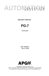
AUTOMATION
P R O D U C T S
G R O U P,
I N C.
Operator’s Manual
PG-5
Full Access
DOC. 9003384
Rev. A1 3/10
Automation Products Group, Inc.
APG...Providing tailored solutions for measurement applications
Tel: 1/888/525-7300 • Fax: 1/435/753-7490 • www.apgsensors.com • E-mail: [email protected]
PG5
Rev. A1, 3/10
Table of Contents
Warranty ............................................................................... 3
Programming the PG5 ....................................................... 4-19
Menu Flow Chart ................................................................ 5
Changing the Mode Setting ............................................... 6
Accessing/Exiting the Setup Menu .................................... 7
Maximum/Minimum Function ........................................... 8
Units of Measure ............................................................... 9
Using Custom Units ................................................... 10
Peak-Hold Feature .......................................................... 11
Advanced Settings...................................................... 12-18
Auto-Off ...................................................................... 12
Decimal Place ............................................................ 13
Sample Rate .............................................................. 14
Bar Graph ................................................................... 15
Range Adjustment ...................................................... 16
Analog Setpoints ........................................................ 17
Analog Calibration ...................................................... 18
Tare Feature .................................................................... 19
Default ............................................................................. 20
Wiring the PG5 .............................................................. 21-23
Firmware Release Notes: .............................................. 24-25
CE Declaration of Conformance ................................... 26-27
Automation Products Group, Inc.
APG...Providing tailored solutions for measurement applications
2
Tel: 1/888/525-7300 • Fax: 1/435/753-7490 • www.apgsensors.com • [email protected]
Rev. A1, 3/10
PG5
• Warranty and Warranty Restrictions
APG warrants its products to be free from defects of material and workmanship
and will, without charge, replace or repair any equipment found defective upon
inspection at its factory, provided the equipment has been returned,
transportation prepaid, within 18 months from date of shipment from factory.
THE FOREGOING WARRANTY IS IN LIEU OF AND EXCLUDES ALL OTHER
WARRANTIES NOT EXPRESSLY SET FORTH HEREIN, WHETHER
EXPRESSED OR IMPLIED BY OPERATION OF LAW OR OTHERWISE
INCLUDING BUT NOT LIMITED TO ANY IMPLIED WARRANTIES OF
MERCHANTABILITY OR FITNESS FOR A PARTICULAR PURPOSE.
No representation or warranty, express or implied, made by any sales
representative, distributor, or other agent or representative of APG which is not
specifically set forth herein shall be binding upon APG. APG shall not be liable
for any incidental or consequential damages, losses or expenses directly or
indirectly arising from the sale, handling, improper application or use of the
goods or from any other cause relating thereto and APG’s liability hereunder, in
any case, is expressly limited to the repair or replacement (at APG’s option) of
goods.
Warranty is specifically at the factory. Any on site service will be provided at
the sole expense of the Purchaser at standard field service rates.
All associated equipment must be protected by properly rated electronic/
electrical protection devices. APG shall not be liable for any damage due to
improper engineering or installation by the purchaser or third parties. Proper
installation, operation and maintenance of the product becomes the
responsibility of the user upon receipt of the product.
Returns and allowances must be authorized by APG in advance. APG will
assign a Return Material Authorization (RMA) number which must appear on
all related papers and the outside of the shipping carton. All returns are subject
to the final review by APG. Returns are subject to restocking charges as
determined by APG’s “Credit Return Policy”.
Automation Products Group, Inc.
APG...Providing tailored solutions for measurement applications
Tel: 1/888/525-7300 • Fax: 1/435/753-7490 • www.apgsensors.com • [email protected]
3
PG5
Rev. A1, 3/10
Programming the PG5
Z Button
Battery Meter
On/Off Button
S Button
Bar Graph
Each of the three buttons on the PG5 performs multiple functions. The primary
function applies when in standard operating mode. The secondary functions
are used for programming operations and when special features, such as PeakHold, are enabled.
On/Off Button
Primary Function: Press and hold for 1 second to turn on/off the gauge.
Secondary Function: Press once to access the main setup menu.
Z Button
Primary Function: Press to “zero” the gauge reading (the reading must be less
than 5% of full-scale in order to zero the gauge).
Secondary Function: Cycles through the options in the setup menus.
S Button
Primary Function: Cycles between the current, maximum, and minimum pressure
readings.
Secondary Function: Used to accept the displayed option while in the setup
menus.
Secondary Function: Resets the peak-hold reading when the peak-hold feature
is enabled.
Automation Products Group, Inc.
APG...Providing tailored solutions for measurement applications
4
Tel: 1/888/525-7300 • Fax: 1/435/753-7490 • www.apgsensors.com • [email protected]
Rev. A1, 3/10
PG5
Automation Products Group, Inc.
APG...Providing tailored solutions for measurement applications
Tel: 1/888/525-7300 • Fax: 1/435/753-7490 • www.apgsensors.com • [email protected]
5
PG5
Rev. A1, 3/10
Accessing the Mode Setting:
Step 1: Simultaneously press and hold the On/Off button and the (S) button
for approximately 3 seconds. This will bring up the 3 digit mode
number.
Step 2: Enter the desired mode number (see mode definitions below)
by using (Z) to change the value of the flashing digit, and (S) to
advance to the next digit.
Mode Definitions:
Mode 000: Full Access
- Provides access to all menu settings. If no buttons are pushed for 1
minute, the gauge will revert back to Mode 003 (factory default).
Mode 002: Limited Access
- Menu is locked
- (Z) button zeros the reading
- (S) cycles between the Max and Min readings
- On/Off functions only on battery powered gauges
Mode 003: Factory Default
- Full access except Full Scale Calibration is locked
Mode 005: Locked Access
- All buttons locked except the on/off button on battery powered
gauges.
Automation Products Group, Inc.
APG...Providing tailored solutions for measurement applications
6
Tel: 1/888/525-7300 • Fax: 1/435/753-7490 • www.apgsensors.com • [email protected]
Rev. A1, 3/10
Z Button
PG5
On/Off Button
S Button
Accessing the Main Setup Menu:
Step 1: With gauge powered on, press the On/Off button once to enter
the main setup menu.
Step 2: Press (Z) to scroll through menu choices; max/min, units, peakhold, advanced settings, tare, default and exit.
Exiting the Main Setup Menu:
Step 1:
Step 2:
Step 3:
Step 4:
While in the main setup menu, press (Z) until EXIT is displayed.
Press (S) to access the Exit options.
Press (Z) to until YES is displayed.
Press (S) to Exit the main setup menu and return to the standard
operating mode.
Automation Products Group, Inc.
APG...Providing tailored solutions for measurement applications
Tel: 1/888/525-7300 • Fax: 1/435/753-7490 • www.apgsensors.com • [email protected]
7
PG5
Rev. A1, 3/10
• Maximum/Minimum Reset (MAXMIN):
Pressing the (S) button while in standard operating mode will cycle between
displaying the current pressure reading, the Maximum pressure reading and the
Minimum pressure reading. The maximum and minimum readings will be stored
until the gauge is powered down or the max/min readings are reset.
Resetting the Max/Min readings:
Step 1:
Step 2:
Step 3:
Step 4:
Step 5:
Press the On/Off button once to enter the main setup menu.
Press (Z) to cycle through the options until MAXMIN is displayed.
Press (S) to access the Max/Min reset options.
Press (Z) to toggle between YES and NO until YES is displayed.
Press (S) to reset the Max/Min readings and return to the main setup
menu.
Automation Products Group, Inc.
APG...Providing tailored solutions for measurement applications
8
Tel: 1/888/525-7300 • Fax: 1/435/753-7490 • www.apgsensors.com • [email protected]
Rev. A1, 3/10
PG5
• Units of Measure (UNITS):
Allows the user to select the unit of measure to be displayed as the pressure
reading.
Options:
For gauges over 120 psi:
PSI
(pounds per square inch)
bAR
(bar)
KPA
(kilopascals)
*CUSTOM
(see “Using Custom Units” on next page)
KGCM^2
(kilograms per cubic centimeter)
MPA
(megapascals)
FTH20
(feet of water @ 60 F)
cmHG
(centimeters of mercury)
For gauges less than 120 psi:
PSI
(pounds per square inch)
bAR
(bar)
KPA
(kilopascals)
*CUSTOM
(see “Using Custom Units” on next page)
mbAR
(millibar)
INHG
(inches of mercury)
INH20
(inches of water @ 60 F)
mmHG
(millimeters of mercury)
Setting the Unit of Measure:
Step 1:
Step 2:
Step 3:
Step 4:
Press the On/Off button once to enter the main setup menu.
Press (Z) to cycle through the options until UNITS is displayed.
Press (S) to access the Units options.
Press (Z) to cycle through setting options until the desired unit of
measure is displayed.
Step 5: Press (S) to apply the setting and return to the main setup menu.
Automation Products Group, Inc.
APG...Providing tailored solutions for measurement applications
Tel: 1/888/525-7300 • Fax: 1/435/753-7490 • www.apgsensors.com • [email protected]
9
PG5
Rev. A1, 3/10
Using Custom Units (CUSTOM):
The Custom Units setting allows the user to display a volumetric weight by
applying a conversion factor to the pressure reading.
NOTE: The conversion factor must be calculated using Pound per Square Inch
(psi) as the base unit of measure.
Setting the Custom Units feature:
Step 1:
Step 2:
Step 3:
Step 4:
Step 5:
Calculate the conversion factor from psi to the desired unit of measure.
Press the On/Off button once to enter the main setup menu.
Press (Z) to cycle through the options until UNITS is displayed.
Press (S) to access the Units setting options.
Press (Z) to cycle through the Units options until CUSTOM is
displayed.
Step 6: Press (S) to access the Custom Units setting. A 5-digit conversion
factor will appear with the first digit flashing.
Step 7: Press (Z) to change the value of the flashing digit (options: 0-9).
Step 8: Press (S) to accept the flashing digit and advance to the next
digit......repeat steps 7 and 8 as necessary.
Step 9: After the last digit is accepted by pressing (S), use (Z) to scroll
through the custom units of measure; LBF, KN, LBS, KG, and
NEWTON.
Step 10: Press (S) to accept the custom unit and return to the main setup
menu.
Automation Products Group, Inc.
APG...Providing tailored solutions for measurement applications
10
Tel: 1/888/525-7300 • Fax: 1/435/753-7490 • www.apgsensors.com • [email protected]
Rev. A1, 3/10
PG5
• Peak-Hold (P HOLd):
When the Peak-Hold is enabled, the gauge will display the “peak” or maximum
pressure reading since the gauge was powered on or the Max/Min value was
reset.
NOTE 1: When the Peak-Hold feature is enabled, a small box containing the
words PEAK HOLD will be displayed in the upper left corner of the
display.
Options: Off or On
Enabling the Peak-Hold feature:
Step 1:
Step 2:
Step 3:
Step 4:
Step 5:
Press the On/Off button to enter the main setup menu.
Press (Z) to cycle through the options until P HOLd is displayed.
Press (S) to access the Peak-Hold setting options.
Press (Z) to toggle between OFF and ON.
Press (S) to apply the displayed setting and return to main setup menu.
NOTE 2: The peak value can be reset by pressing (S) with the Peak-Hold
function enabled.
Automation Products Group, Inc.
APG...Providing tailored solutions for measurement applications
Tel: 1/888/525-7300 • Fax: 1/435/753-7490 • www.apgsensors.com • [email protected]
11
PG5
Rev. A1, 3/10
• Advanced Settings (AdVSET):
The Advanced Settings menu is used to customize the LCD display and to
setup any optional features, such as an analog output.
Auto-Off (AUTO):
This function is applicable to battery powered units only. The Auto-Off feature
allows the user to designate the time of inactivity (no buttons pushed) until the
gauge automatically powers down.
Options: 2 MIN, 4 MIN, 8 MIN, 16 MIN, 32 MIN and OFF
NOTE: Selecting OFF disables the Auto-Off feature; the gauge will then remain
powered indefinitely as long as there is sufficient voltage being
supplied (~3.3V).
Setting the Auto-Off feature:
Step 1: Press the On/Off button to enter the main setup menu.
Step 2: Press (Z) to cycle through the menu options until AdVSET is
displayed.
Step 3: Press (S) to enter the Advanced Settings menu.
Step 4: Press (Z) to cycle through the menu options until AUTO is displayed.
Step 5: Press (S) to access the Auto-Off setting options.
Step 6: Press (Z) to cycle through setting options until the desired setting is
displayed.
Step 7: Press (S) to apply the setting and return to main setup menu.
Automation Products Group, Inc.
APG...Providing tailored solutions for measurement applications
12
Tel: 1/888/525-7300 • Fax: 1/435/753-7490 • www.apgsensors.com • [email protected]
Rev. A1, 3/10
PG5
Decimal Place (dEC PL):
The reading can be set to display in High Resolution (HI RES) or Low
Resolution (LO RES) mode. Switching between high and low resolution will
shift the displayed reading by one decimal place position.
NOTE: When Low Resolution mode is enabled on a gauge with 0 decimal place
positions, the display will increment in factors of 10.
Options: HI RES (high resolution) or LO RES (low resolution)
Setting the Decimal Place feature:
Step 1: Press the On/Off button to enter the main setup menu.
Step 2: Press (Z) to cycle through the menu options until AdVSET is
displayed.
Step 3: Press (S) to enter the Advanced Settings menu.
Step 4: Press (Z) to cycle through the options until dEC PL is displayed.
Step 5: Press (S) to access the Decimal Place setting options.
Step 6: Press (Z) to cycle between HI RES (high resolution) and LO RES (low
resolution).
Step 7: Press (S) to apply the displayed setting and return to main setup menu.
Automation Products Group, Inc.
APG...Providing tailored solutions for measurement applications
Tel: 1/888/525-7300 • Fax: 1/435/753-7490 • www.apgsensors.com • [email protected]
13
PG5
Rev. A1, 3/10
Sample Rate (SAMPLE):
Adjusts the rate at which the gauge takes sample readings.
NOTE: Setting the Sample Rate to “SLOW” will help preserve battery life
(when applicable) and will also help to smooth rapidly fluctuating
readings.
Options: SLOW (4x/second), MEdIUM (8x/second), FAST (16x/second)
Setting the Sample Rate feature:
Step 1:
Step 2:
Step 3:
Step 4:
Step 5:
Step 6:
Press the On/Off button to enter the main setup menu.
Press (Z) to cycle through the options until AdVSET is displayed.
Press (S) to access the Advanced Settings menu.
Press (Z) to cycle through the options until SAMPLE is displayed.
Press (S) to access the Sample Rate setting options.
Press (Z) to cycle through the setting options until the desired setting
is displayed.
Step 7: Press (S) to apply the displayed setting and return to main setup menu.
Automation Products Group, Inc.
APG...Providing tailored solutions for measurement applications
14
Tel: 1/888/525-7300 • Fax: 1/435/753-7490 • www.apgsensors.com • [email protected]
Rev. A1, 3/10
PG5
Bar Graph 0% (bAR 0) & 100% (bAR100) Settings:
Allows the user to define the reading values associated with 0% and
100% on the display bar graph. Bars will appear/disappear in 10%
increments of the total span between the two values.
NOTE: The 0% reference does not have to be the lower pressure
setting; 0% can be set as the higher pressure setting, thereby
causing the bar graph to increase as the pressure decreases.
Negative pressure settings can also be used as either the 0% or 100%
reference points.
Setting the Display Bar Graph:
Step 1:
Step 2:
Step 3:
Step 4:
Step 5:
Press the On/Off button once to enter the main setup menu.
Press (Z) to cycle through the options until AdVSET is displayed.
Press (S) to access the Advanced Settings menu.
Press (Z) to cycle through the options until BAR 0 is displayed.
Press (S) to access the Bar Graph 0% value. A 5-digit number will
appear with the first digit flashing.
Step 6: Press (Z) to change the value of the first flashing digit
(options: 0-9 or “-”).
Step 7: Press (S) to accept the value of the flashing digit and advance to the
next digit......repeat steps 7 and 8 until the desired 0% reading is fully
entered. After the last digit is accepted by pressing (S), the display will
return to the main options menu.
Step 8: Press (S) to reenter the Advanced Settings menu.
Step 9: Press (Z) to cycle through the options until BAR100 is displayed.
Step 10: Repeat Steps 5-7 to enter the Bar Graph 100% value.
Automation Products Group, Inc.
APG...Providing tailored solutions for measurement applications
Tel: 1/888/525-7300 • Fax: 1/435/753-7490 • www.apgsensors.com • [email protected]
15
PG5
Rev. A1, 3/10
Full-Scale Range Adjust (RANGE):
Allows the user to adjust the reading at full-scale pressure. The reading can be
adjusted by +/-10% full-scale.
NOTE: The pressure reading must be within 5% of the full-scale value in order
to make Range adjustments. For example, a 1000 psi gauge would need
to be reading between 950 psi and 1050 psi in order to adjust the Range
feature. If the reading is not within 5% of full scale, NOAdJU (No
Adjustment) will be displayed when trying to adjust the Range.
Adjusting the Full-Scale Range:
Step 1:
Step 2:
Step 3:
Step 4:
Step 5:
Step 6:
Step 7:
Step 8:
Ensure that the pressure reading is within 5% of full-scale.
Press the On/Off button to enter the main setup menu.
Press (Z) to cycle through the options until AdVSET is displayed.
Press (S) to access the Advanced Settings menu.
Press (Z) to cycle through the options until RANGE is displayed..
Press (S) to enter the Range adjust mode.
Press (Z) to increase the reading, or press (S) to decrease the reading.
Press the On/Off button to accept the adjusted reading and return to
the main setup menu.
Automation Products Group, Inc.
APG...Providing tailored solutions for measurement applications
16
Tel: 1/888/525-7300 • Fax: 1/435/753-7490 • www.apgsensors.com • [email protected]
Rev. A1, 3/10
PG5
Analog Low (AL SET) & Analog High (AH SET) Setpoints:
Allows the user to define the reading values associated with the Low Analog
signal (i.e. 4mA or 0V) and the High Analog signal (i.e. 20mA, 2V or 5V).
NOTE: The analog signal can be spanned over any portion of the pressure
range, and can also be inverted by setting the Analog Low Setpoint as
the higher pressure value. Negative pressure values can also be used
as either the Analog High or Analog Low Setpoints.
Setting the Analog Signal Span:
Step 1:
Step 2:
Step 3:
Step 4:
Step 5:
Press the On/Off button once to enter the main setup menu.
Press (Z) to cycle through the options until AdVSET is displayed.
Press (S) to access the Advanced Settings menu.
Press (Z) to cycle through the options until AL SET is displayed.
Press (S) to access the Analog Low setpoint value. A 5-digit number
will appear with the first digit flashing.
Step 6: Press (Z) to change the value of the first flashing digit
(options: 0-9 or “-”).
Step 7: Press (S) to accept the value of the flashing digit and advance to the
next digit......repeat steps 7 and 8 until the desired Analog Low reading
is fully entered. After the last digit is accepted by pressing (S), the
display will return to the main options menu.
Step 8: Press (S) to reenter the Advanced Settings menu.
Step 9: Press (Z) to cycle through the options until AH SET is displayed.
Step 10: Repeat Steps 5-7 to enter the Analog High setpoint value.
Automation Products Group, Inc.
APG...Providing tailored solutions for measurement applications
Tel: 1/888/525-7300 • Fax: 1/435/753-7490 • www.apgsensors.com • [email protected]
17
PG5
Rev. A1, 3/10
Analog Low (AL CAL) & Analog High (AH CAL) Calibration:
Allows the user to calibrate or “trim” the endpoints of the analog signal output
(i.e. 4mA & 20mA or 0V & 2V/5V)
Calibrating the Analog Signal End-Points:
Step 1: Use a calibrated meter to monitor the analog output signal.
Step 2: Force a low analog output signal (i.e. 4mA or 0V) either by adjusting
the applied pressure or by adjusting the Analog Setpoints (see
“Analog Setpoints” on page 18 for details).
Step 3: Press the On/Off button once to enter the main setup menu.
Step 4: Press (Z) to cycle through the options until AdVSET is displayed.
Step 5: Press (S) to access the Advanced Settings menu.
Step 6: Press (Z) to cycle through the setup options until AL CAL is displayed.
Step 7: Press (S) to access the Analog Low Calibration value. A 5-digit number
will appear with the first digit flashing.
Step 8: Press (Z) to change the value of the flashing digit.
NOTE: Increasing this 5-digit number will increase the output signal. Changing
the digit farthest to the left will produce the coarsest adjustment, while
each successive digit moving to the right will cause subsequently finer
adjustments to the output signal.
Step 9: Press (S) to accept the value of the flashing digit and advance to the
next digit......repeat steps 7 and 8 until the desired Analog Output
Signal displayed ont he meter. After the last digit is accepted by
pressing (S), the display will return to the main setup menu.
Step 10: Press (S) to reenter the Advanced Settings menu.
Step 11: Press (Z) to cycle through the options until AH CAL is displayed.
Step 12: Repeat Steps 5-7 to adjust the Analog High Calibration value.
Automation Products Group, Inc.
APG...Providing tailored solutions for measurement applications
18
Tel: 1/888/525-7300 • Fax: 1/435/753-7490 • www.apgsensors.com • [email protected]
Rev. A1, 3/10
PG5
• Tare (TARE):
Enabling the Tare function will set the current pressure reading as the zero
reference pressure in order to measure a net change in pressure as opposed to
measuring the gross pressure.
Enabling the Tare feature:
Step 1:
Step 2:
Step 3:
Step 4:
Step 5:
Press the On/Off button once to enter the main setup menu.
Press (Z) to cycle through the options until TARE is displayed.
Press (S) to access the Tare setting options.
Press (Z) to toggle between OFF and ON.
Press (S) button to apply the displayed options and return to main
setup menu.
NOTE 1: When tare function is enabled, the T5 symbol will appear in the lower
left corner of the display.
WARNING: Do NOT disconnect the gauge from the pressure fitting while the
tare function is enabled. The gauge may still be under pressure
even though the reading shows 0.
NOTE 2: If the maximum gross full-scale pressure value is reached while the
Tare feature is enabled, the PG5 will automatically disable the Tare
feature and return to reading the gross pressure in order to help
prevent the user from unwittingly overpressuring the gauge.
Automation Products Group, Inc.
APG...Providing tailored solutions for measurement applications
Tel: 1/888/525-7300 • Fax: 1/435/753-7490 • www.apgsensors.com • [email protected]
19
PG5
Rev. A1, 3/10
• Default (dEFAUL):
Used to reset the gauge to the factory default settings.
Resetting the gauge to factory default settings:
Step 1:
Step 2:
Step 3:
Step 4:
Step 5:
Press the On/Off button once to enter the main setup menu.
Press (Z) to cycle through the options until dEFAUL is displayed.
Press (S) to access the Default options.
Press (Z) to cycle between NO and YES.
Press (S) to apply the displayed setting and return to main setup menu.
Automation Products Group, Inc.
APG...Providing tailored solutions for measurement applications
20
Tel: 1/888/525-7300 • Fax: 1/435/753-7490 • www.apgsensors.com • [email protected]
Rev. A1, 3/10
PG5
Wiring the PG5
Battery Replacement:
The battery is accessed by removing the single screw at the top of the battery
cover on the back of the gauge.
NOTE: Do not overtighten the screw when securing the battery cover.
Externally Powered, No Output:
Externally powered gauges without an analog output are powered using an 1/8
inch stereo jack connector (mate supplied) on the back of the gauge. The “Tip”
connection is “+ Power” and the “Center” connection is “- Power”.
WARNING: Always turn off the supply power before inserting or removing the
stereo jack plug. Failure to do so can damage the gauge.
Supply -
Supply +
NOTE: Do not connect to the stereo jack’s case connection.
Automation Products Group, Inc.
APG...Providing tailored solutions for measurement applications
Tel: 1/888/525-7300 • Fax: 1/435/753-7490 • www.apgsensors.com • [email protected]
21
PG5
Rev. A1, 3/10
4-20 mA Option (loop powered):
6 Pin Connector
F
A
B
E
D
C
NOTE 1: The supply voltage must be sufficient to maintain a minimum of 9 VDC
after “dropping” voltage across the load resistance with the output at
20mA. Example: If RL = 250 ohm then “drop” is 0.02 Amps X 250 ohm
= 5 volts. Therefore power supply minimum is 5 V + 9 V = 14 V.
NOTE 2: Completion of the earth ground (Pin F) is recommended for proper
circuit protection.
Externally powered with 0-5 VDC or 0-2 VDC analog output:
6 Pin Connector
F
A
B
E
D
C
NOTE: Completion of the earth ground (Pin F) is recommended for proper
circuit protection.
Automation Products Group, Inc.
APG...Providing tailored solutions for measurement applications
22
Tel: 1/888/525-7300 • Fax: 1/435/753-7490 • www.apgsensors.com • [email protected]
Rev. A1, 3/10
PG5
Battery powered with 0-2 VDC output option:
The 0–2 VDC signal is accessed through a stereo jack connection on the back
of the gauge.
0-2 VDC Output
Tip
Center
Body
+ Output
– Output
No connection
NOTE 1: Do not connect to the stereo jack’s case connection.
NOTE 2: To minimize the effect on the battery life, the output should not be
loaded with less than 100k ohms.
Automation Products Group, Inc.
APG...Providing tailored solutions for measurement applications
Tel: 1/888/525-7300 • Fax: 1/435/753-7490 • www.apgsensors.com • [email protected]
23
PG5
Rev. A1, 3/10
Firmware Release Notes
PG5v100.hex Created 1/20/2009
First Release of Software
PG5V101.hex Created 2/13/2009
-> Updated Zero function to read NOZERO when more than 5% of Full Scale
-> Updated Tare function to read NOTARE when more than full scale and if gauge is in TARE T5 segment instead of T1
and shuts off when greater than full scale
-> Fixed On/Off button on Power Up to wait to be released before going into the Menu
PG5v102.hex Created 3/16/2009
-> Added different sampling rates selectable from the Menu slow,medium,fast
-> Disabled the lo res option for units with no decimal place in reading
-> Fixed Peak Hold to Reset by pushing Select Button to reset the max value to the current reading
-> Fixed the Leading Zeros when Peak Hold enabled and when using the Custom Multiplier in the Menu
-> Locked Menu has peak hold enable/disable with Select button not in Menu, Menu has Units -> lbs,kg, Newton -> Can
Zero Reading Z button
-> Fixed External Power Auto_Off Option and Sampling Rate
-> Fixed ON/OFF Button when Auto_Off enabled it went into the MENU reset the Flag when Auto Off shutdown
-> Reset Auto Off timer every time the Zero or Select Button are pushed.
PG5v103.hex 4/7/2009
-> Added 4 options to setup the analog output from the menu and appear only with ouputs enabled
-> Added fsw to units and changed to lockout all other units when calibration to other unit besides psi
-> Added Bar Graph Zero and Full Scale adjustment to the Menu
-> Added Range adjustment in the Menu
-> Added Modes to Lockout the Menu and give limited access
PG5v104.hex created 4/27/2009
-> Changed how Units are displayed when other than psi only that unit is displayed
PG5v105.hex created 5/27/2009
-> Fixed conversion problems with units ftH20, cmHg
-> Fixed Bar Graph zero and Full Scale to scale to the right pressure
-> Fixed High and Lo Res for the different units and to have a dummy zero for correct units
Automation Products Group, Inc.
APG...Providing tailored solutions for measurement applications
24
Tel: 1/888/525-7300 • Fax: 1/435/753-7490 • www.apgsensors.com • [email protected]
Rev. A1, 3/10
PG5
Firmware Release Notes (continued)
PG5v106.hex created 6/19/2009
-> Renamed the SETUP options displayed for bargraph and analog output setup.
-> Made Max reading not reset using shortcut only allowed in MENU Reset
-> By pressing S while not in Menu the max, then min values are displayed
-> Added Decimal Place while setting the bargraph to the psi equivalent.
-> Added Decimal Place for Analog Output Set points
-> Renamed SETUP to ADVSET in Menu
-> When changing range the value then overwrites the default multiplier for field calibration
PG5v107.hex created 8/12/09
-> If Tare is enabled and not in the menu the Z button will rezero the pressure reading
-> Added Units of Measure TONS for customer
PG5v108.hex created 11/15/09
-> Fixed Bar Graph when recalibrating gauge using the range function in the menu.
-> Fixed Glitch with Updating Range and re-zeroing gauge in Mode 000.
PG5v109.hex created 12/11/09
-> Fixed Glitch with entering mode 2 and returning to mode 3 for special calibration units which changed the units of
measure.
-> Fixed Hi and Low resolution glitch with different units of measure.
Automation Products Group, Inc.
APG...Providing tailored solutions for measurement applications
Tel: 1/888/525-7300 • Fax: 1/435/753-7490 • www.apgsensors.com • [email protected]
25
PG5
Rev. A1, 3/10
Automation Products Group, Inc.
APG...Providing tailored solutions for measurement applications
26
Tel: 1/888/525-7300 • Fax: 1/435/753-7490 • www.apgsensors.com • [email protected]
Rev. A1, 3/10
PG5
Automation Products Group, Inc.
APG...Providing tailored solutions for measurement applications
Tel: 1/888/525-7300 • Fax: 1/435/753-7490 • www.apgsensors.com • [email protected]
27
AUTOMATION
P R O D U C T S
G R O U P, I N C.
APG...Providing tailored solutions
for measurement applications
Automation Products Group, Inc.
Tel: 1/888/525-7300
1/435/753-7300
Fax: 1/435/753-7490
e-mail: [email protected]
www.apgsensors.com
Automation Products Group, Inc.
1025 W. 1700 N.
Logan, UT 84321
To order additional copies of this manual, ask for APG part number PN9003384 Rev. A1, 3/10