1
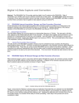
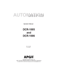
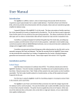
AUTOMATION
P R O D U C T S
G R O U P,
I N C.
Operator’s Manual
DCU-1104
and
DCU-1108
Rev. A2, 11/06
Doc. 9002660
Automation Products Group, Inc.
APG...Providing tailored solutions for measurement applications
Tel: 1/888/525-7300 • Fax: 1/435/753-7490 • www.apgsensors.com • E-mail: [email protected]
DCU-1104 and DCU-1108
Rev. A2, 11/06
Table of Contents
Warranty ......................................................................................... 3
Introducing ...................................................................................... 4
Understanding Ultrasonics ............................................................. 5
Installation ...................................................................................... 7
Wiring .............................................................................................. 9
Programming ................................................................................ 11
Operation ................................................................................... 12
Filtering ..................................................................................... 13
Outputs ...................................................................................... 15
Calibration ................................................................................. 19
Utilities ...................................................................................... 21
Lift Station Example .................................................................. 23
Mode Sheet ................................................................................... 25
Hazardous Mounting ..................................................................... 29
Specifications ................................................................................ 30
Automation Products Group, Inc.
APG...Providing tailored solutions for measurement applications
2
Tel: 1/888/525-7300 • Fax: 1/435/753-7490 • www.apgsensors.com • [email protected]
Rev. A2, 11/06
DCU-1104 and DCU-1108
• Warranty and Warranty Restrictions
APG warrants its products to be free from defects of material and workmanship
and will, without charge, replace or repair any equipment found defective upon
inspection at its factory, provided the equipment has been returned,
transportation prepaid, within 24 months from date of shipment from factory.
THE FOREGOING WARRANTY IS IN LIEU OF AND EXCLUDES ALL OTHER
WARRANTIES NOT EXPRESSLY SET FORTH HEREIN, WHETHER
EXPRESSED OR IMPLIED BY OPERATION OF LAW OR OTHERWISE
INCLUDING BUT NOT LIMITED TO ANY IMPLIED WARRANTIES OF
MERCHANTABILITY OR FITNESS FOR A PARTICULAR PURPOSE.
No representation or warranty, express or implied, made by any sales
representative, distributor, or other agent or representative of APG which is not
specifically set forth herein shall be binding upon APG. APG shall not be liable
for any incidental or consequential damages, losses or expenses directly or
indirectly arising from the sale, handling, improper application or use of the
goods or from any other cause relating thereto and APG’s liability hereunder, in
any case, is expressly limited to the repair or replacement (at APG’s option) of
goods.
Warranty is specifically at the factory. Any on site service will be provided at
the sole expense of the Purchaser at standard field service rates.
All associated equipment must be protected by properly rated electronic/
electrical protection devices. APG shall not be liable for any damage due to
improper engineering or installation by the purchaser or third parties. Proper
installation, operation and maintenance of the product becomes the
responsibility of the user upon receipt of the product.
Returns and allowances must be authorized by APG in advance. APG will
assign a Return Material Authorization (RMA) number which must appear on
all related papers and the outside of the shipping carton. All returns are subject
to the final review by APG. Returns are subject to restocking charges as
determined by APG’s “Credit Return Policy”.
Automation Products Group, Inc.
APG...Providing tailored solutions for measurement applications
Tel: 1/888/525-7300 • Fax: 1/435/753-7490 • www.apgsensors.com • [email protected]
3
DCU-1104 and DCU-1108
Rev. A2, 11/06
• Introducing
Thank you for purchasing the DCU-11 Programmable Ultrasonic Sensor.
These sensors combine a versatile range of features to handle even the toughest
measuring challenges in tank and environmental monitoring and control.
Sensor features include:
• Total Programmability
• Built-in display for easy setup and distance readings
• Rugged, PVC housing for harsh environments with polyurethane
encased electronics for moisture, shock, and vibration resistance
• Microprocessor-controlled with analog and relay outputs
• PVC enclosed ceramic transducer for use in wet or dry applications
• Distance range of 2 ft. to 50 ft.
3.5"
1/2" NPT
12.5"
3" NPT
Automation Products Group, Inc.
APG...Providing tailored solutions for measurement applications
4
Tel: 1/888/525-7300 • Fax: 1/435/753-7490 • www.apgsensors.com • [email protected]
Rev. A2, 11/06
DCU-1104 and DCU-1108
• Understanding Ultrasonics
Ultrasonic sensors measure distance
using a transducer to send out ultrasonic
bursts. Each burst contains a series of 120 pulsed sound waves that emit in the
shape of a cone, reflect off the target, and
are received by the sensor. The time
required for the sound burst to travel to
and from the target is converted into a
distance measurement by the sensor.
Ultrasonic sensing is affected by
several factors including the target
surface, distance, size, and angle. The
following considerations will help ensure
the best possible target conditions.
low sensitivity
and
pulses
detection
area
high sensitivity
and
pulses
beam spread
Surface
The ideal target surface is hard and smooth and perpendicular to the face of
the transducer. This surface will reflect a greater amount of signal than a soft,
sound wave absorbent surface. A target with poor sound wave reflection
characteristics will reduce the operating distance of the sensor and decrease its
accuracy.
Automation Products Group, Inc.
APG...Providing tailored solutions for measurement applications
Tel: 1/888/525-7300 • Fax: 1/435/753-7490 • www.apgsensors.com • [email protected]
5
DCU-1104 and DCU-1108
Rev. A2, 11/06
Distance
The shorter the distance from the sensor to an object, the stronger the
returning echo will be. Therefore, as the distance increases, the object requires
better reflective characteristics to return a sufficient echo.
Size
A large object will have a greater surface area to reflect the signal than a
small one, therefore, a large target will be detected at a greater distance than a
small target. The surface area recognized as the target is generally the portion
closest to the sensor.
Angle
The inclination of the object's surface facing the ultrasonic sensor affects the
reflectivity of the object. The portion perpendicular to the sensor returns the
echo. If the entire surface is at a great enough angle, the signal will be reflected
away from the sensor and no echo will be detected. Generally a target at an
angle greater than 5 degrees off perpendicular will not be detected.
Automation Products Group, Inc.
APG...Providing tailored solutions for measurement applications
6
Tel: 1/888/525-7300 • Fax: 1/435/753-7490 • www.apgsensors.com • [email protected]
Rev. A2, 11/06
DCU-1104 and DCU-1108
• Installation
1. Installation, use and maintenance shall be in
accordance with the manufacturer’s instructions, the
National Electrical Code and any applicable local codes.
2. Electrical equipment connected to associated
apparatus should not use or generate more than
250Vrms.
3. Tampering or replacement with nonfactory
components may adversely affect the safe use of the
system.
Automation Products Group, Inc.
APG...Providing tailored solutions for measurement applications
Tel: 1/888/525-7300 • Fax: 1/435/753-7490 • www.apgsensors.com • [email protected]
7
DCU-1104 and DCU-1108
Rev. A2, 11/06
• Installation
The DCU-11 sensor should be mounted so that it has a clear sound path to
the level monitored. Mount the sensor away from tank walls and inlets. The
path should be free from obstructions and as open as possible for the 18° beam
pattern (9° off axis). Follow the guidelines mentioned in "Understanding
Ultrasonics", earlier in this manual. When using a stand pipe to mount the
sensor above the tank, the stand pipe should be seamless and no longer than 4
in. to provide a smooth path for the sound waves to propagate into the tank.
Seams from couplers, nipples or gaskets can cause erroneous echoes and
degrade the sensors performance.
The DCU-11 can be mounted in a coupler, or flange by using the 3 in.
threaded case. It can also be mounted using a Uni-Strut mounting bracket.
The minimum detection range of the DCU-11 is 2 ft. The sensor should be
mounted to ensure the target does not come closer than the minimum
range or erroneous readings may result.
To mount the DCU-11 for Class 1 Division 2 Groups A, B, C, and D, see the
Hazardous Mounting section of this manual.
Stand Pipe
Top of Tank
o
10-45 CUT
*Soft gasket
material is
recommended with
flange mounting.
Automation Products Group, Inc.
APG...Providing tailored solutions for measurement applications
8
Tel: 1/888/525-7300 • Fax: 1/435/753-7490 • www.apgsensors.com • [email protected]
Rev. A2, 11/06
DCU-1104 and DCU-1108
• Wiring
RED ................... 10 - 30 VDC (24 VDC recommended)
BLACK .............. POWER SUPPLY GROUND
YELLOW ........... ANALOG GROUND
ORANGE ........... 4-20 mA ANALOG OUTPUT
BLUE ................. RELAY 1 COMMON
GRAY ................ RELAY 1 NORMALLY OPEN
PURPLE ............ RELAY 2 COMMON
BROWN ............. RELAY 2 NORMALLY OPEN
GREEN .............. CLOCK SYNCHRONIZATION
WHITE ............... DIGITAL OUT
SHIELD ............. TERMINATE AT POWER SOURCE *
• Cable is a 10 conductor with shield, 22 AWG, 6 ft. (1.83 m) length.
• Ground and Analog ground are connected internal to the DCU-11.
* Shield is not connected in the DCU-11 and should be grounded at the
power source.
Wiring for Clock
Synchronization
The DCU-11 has the
capability to synchronize
the transmit pulses of
multiple sensors. When
sensors are mounted in
close proximity to one
another the sensors
should be synchronized to
help prevent cross talk
between sensors.
Wiring for a Digital
Out
The digital output is a pulse width signal which corresponds to the distance
being detected by the DCU-11 sensor. The digital signal is typically used in
conjunction with a APG (ACC-1007) or (ACC-1008) remote readout.
Automation Products Group, Inc.
APG...Providing tailored solutions for measurement applications
Tel: 1/888/525-7300 • Fax: 1/435/753-7490 • www.apgsensors.com • [email protected]
9
DCU-1104 and DCU-1108
Rev. A2, 11/06
Wiring for a Relay Output
When switching a highly capacitive or inductive load, a swamping diode
should be used. This will protect the internal relay from possible damage and
prevent electrical noise from being introduced to the sensor which could result
in false readings.
DCU-11 Wiring Diagram
A.C.
24VDC
24VDC
24 V DC
COIL
RELAY
Swamping Diode
Alarm
Brown (N.O.)
Purple (Common)
Gray (N.O.)
Blue (Common)
Power Supply
ACC-1008
24VDC Neg.
5 Volts
Red 10-30VDC
Black Neg.
0 Volts
White
White Digital out
Length of time for
signal to travel from
transducer to target
and return to
transducer. The width
varies and is proportional
to the target distance.
Orange 4-20mA (+)
I/O Device
Yellow 4-20mA (-)
Automation Products Group, Inc.
APG...Providing tailored solutions for measurement applications
10
Tel: 1/888/525-7300 • Fax: 1/435/753-7490 • www.apgsensors.com • [email protected]
Rev. A2, 11/06
DCU-1104 and DCU-1108
• Programming
The DCU-11 display and control buttons can be accessed by unscrewing the
sealed cap on the rear of the sensor. The membrane display has two lights
indicating the status of Trip Points 1 and 2. The LED display shows distance
measurements. The display is also used when programming to display the
individual modes and their values.
The DCU-11 has four programming buttons, VALUE UP, VALUE DOWN,
MODE UP and MODE DOWN. They are accessed similar to a digital watch.
To cycle forward through the 27 modes, hold down the MODE UP button. To
cycle backwards through the modes, hold down the MODE DOWN button.
To select a mode, press the MODE UP or MODE DOWN button until the
desired mode is displayed. Press either the VALUE UP or VALUE DOWN
button once to view the selected mode setting.
To change the selected mode setting, hold down the VALUE UP or VALUE
DOWN button until the desired setting is displayed.
To STORE or SAVE the desired change, press the MODE UP or MODE
DOWN button. The display will return to displaying the distance measurement.
The value is also permanently stored in the EE memory and will not be lost
when power is turned off. If a button is not pressed for 2 minutes, the display
will turn off to reduce power requirements. Pressing any button will return the
display to showing it's distance reading.
A list of the 27 modes is located on the DCU-11 MODE SHEET provided
with this manual.
Automation Products Group, Inc.
APG...Providing tailored solutions for measurement applications
Tel: 1/888/525-7300 • Fax: 1/435/753-7490 • www.apgsensors.com • [email protected]
11
DCU-1104 and DCU-1108
Rev. A2, 11/06
Operation
MODE
1
DESCRIPTION
Units
PARAMETERS
Range = 1-3
1- inches
2- feet
3- meters
The first thing to set up on the DCU-11 is the Units to be Displayed. The
Units Mode is used to select the type of measurement and setup units in which
you will operate. The units will also determine the resolution of the display and
the outputs. The resolution is: inches .1, feet .01, and meters .01.
NOTE: All modes must be set using the units in Mode 1.
MODE
2
DESCRIPTION
*Sensitivity
MODE
3
DESCRIPTION
Blanking
PARAMETERS
Units = %
Range = 0000 - 9999
The sensitivity setting adjusts the level of gain/amplification (as a percentage
of maximum) that is applied to the return signal. To avoid amplifying unwanted
noise, set the sensitivity to the minimum value that will allow the target to be
reliably tracked through the full range of environmental conditions. It is often
wise to add another 10% as a buffer.
*NOTE: FOR VIEWING ONLY IN AUTOSENSE MODE (mode- 27). The
first two digits on the display will read the highest sensitivity the sensor can
operate at effectively. The last two digits display the currently operating
sensitivity level of the sensor. The numbers displayed are used to help with
installation.
PARAMETERS
Units = Mode 1
Range = 2-50 ft.
Default = 2.00
The blanking distance is the zone from the sensor to a point where the first
echo will be accepted. Because of the physical properties of an ultrasonic
sensor, objects cannot be detected closer than 2 ft. from the end of the
transducer. This distance varies according to how much energy is being
transmitted (Mode 4) and the installation. Ensure this parameter is entered after
Automation Products Group, Inc.
APG...Providing tailored solutions for measurement applications
12
Tel: 1/888/525-7300 • Fax: 1/435/753-7490 • www.apgsensors.com • [email protected]
Rev. A2, 11/06
DCU-1104 and DCU-1108
the Units (Mode 1) have been set. The blanking distance can also be used to
ignore unwanted targets close to the sensor such as welds, seams, pipe fittings,
or gaskets.
MODE
4
DESCRIPTION
Pulses
PARAMETERS
Units = 42 Khz soundwaves
Range = 1-20
Default = 20
The Pulses mode controls how many pulsed soundwaves are transmitted in
each ultrasonic burst. The DCU-11 sends out a transmission burst of pulses and
measures the time it takes for the echo to return. Up to a certain point, the more
pulses that are sent in a burst, the stronger the returning echo. When detecting a
soft target in damping environments, increase the strength of the echo by
increasing the number of pulses. In acoustically active environments, small
enclosed areas, or hard surface areas, decrease the number of pulses in order to
decrease the energy transmitted and reduce multiple echoes.
Filtering
MODE
5
DESCRIPTION
Sample Rate
PARAMETERS
Units = Seconds
Range = 0.120-1 (1- 8 in AutoSense mode)
Default = 1
The sample rate or time between ultrasonic bursts can be adjusted to achieve
the reaction time needed for the application. Typically, product levels change
slowly requiring a slow sample rate (1-8 seconds).
MODE
6
DESCRIPTION
Averaging
PARAMETERS
Units = Samples
Range = 1-50
Default = 10
Averaging sets the number of samples that will be averaged in the first-infirst-out (FIFO) average buffer. The DCU-11 will take readings at the rate
determined by Mode 5. Therefore, a setting of 10 in Mode 6 with a 1 second
sample rate, would result in a 10 second average updated once each second.
Automation Products Group, Inc.
APG...Providing tailored solutions for measurement applications
Tel: 1/888/525-7300 • Fax: 1/435/753-7490 • www.apgsensors.com • [email protected]
13
DCU-1104 and DCU-1108
MODE
7
DESCRIPTION
Out-of-Range
Samples
MODE
8
DESCRIPTION
Out-of-Range
Span
MODE
9
DESCRIPTION
Loss of Echo
Delay
Rev. A2, 11/06
PARAMETERS
Units = Samples
Range = 1-200
Default = 5
This mode is used in conjunction with Out-of Range Span (Mode 8) to set an
effective window for valid readings. Setting the Out-of-Range Samples to 10
would require that a target be detected 10 times in succession outside of the
window (Mode 8) before the sensor will recognize it as a new valid target and
enter it into the FIFO buffer.
PARAMETERS
Units = Mode 1
Range = 0-9999
Default = 2.00 ft.
The Out-of-Range Span will set a certain size window (+/-) the current
reading. If the echo received is within this window, it will be considered valid
and is averaged in the FIFO buffer.
PARAMETERS
Units = seconds
Range = 0-9999
Default = 5
This mode sets the delay in seconds before the output will show a loss of
echo condition. When the DCU-11 does not receive an echo, it will hold the last
valid condition for the number of seconds entered in Mode 9. When this time
has expired, the display and trip points will change to their maximum distance
reading.
Automation Products Group, Inc.
APG...Providing tailored solutions for measurement applications
14
Tel: 1/888/525-7300 • Fax: 1/435/753-7490 • www.apgsensors.com • [email protected]
Rev. A2, 11/06
DCU-1104 and DCU-1108
Outputs
Relay
The two relays are fully programmable for BEGIN and END points and their
Type of operation. The LEDs on the DCU-11 display labeled TRIP 1 and TRIP
2 indicate the status of the normally open relay contacts. When the LED is on,
the relay is energized and the contact is closed. All distance settings will be in
the UNITS selected in Mode 1.
The relays are rated for 200 mA @ 24 VDC. Switching A.C. through the
relay is not recommended.
NOTE: Outputs do not automatically convert to units used in Mode 1. All
outputs must be changed, if Mode 1 has been changed.
MODE
10
DESCRIPTION
Begin Trip 1
PARAMETERS
Units = Mode 1
Range = 0 - 9999
Default = 3.00
Sets the Begin point for Trip 1 Relay Output.
MODE
11
DESCRIPTION
End Trip 1
MODE
12
DESCRIPTION
Trip 1 Type
PARAMETERS
Units = Mode 1
Range = 0 - 9999
Default = 4.00
Sets the End point for Trip 1 Relay Output.
PARAMETERS
Range = 0 - 7
0 - near
1- exclusive
2 - hysteresis near
3 - far
4 - inclusive
5 - hysteresis far
6 - disable
7 - loss of echo
Default = 0
Selects the output type for Trip 1.
Automation Products Group, Inc.
APG...Providing tailored solutions for measurement applications
Tel: 1/888/525-7300 • Fax: 1/435/753-7490 • www.apgsensors.com • [email protected]
15
DCU-1104 and DCU-1108
MODE
13
DESCRIPTION
Begin Trip 2
MODE
14
DESCRIPTION
End Trip 2
MODE
15
DESCRIPTION
Trip 2 Type
Rev. A2, 11/06
PARAMETERS
Units = Mode 1
Range = 0 - 9999
Default = 3.50
Sets the Begin point for Trip 2 Relay Output.
PARAMETERS
Units = Mode 1
Range = 0 - 9999
Default = 4.50
Sets the End point for Trip 2 Relay Output.
PARAMETERS
Range = 0 - 7
0 - near
1 - exclusive
2 - hysteresis near
3 - far
4 - inclusive
5 - hysteresis far
6 - disable
7 - loss of echo
Default = 0
Selects the output type for Trip 2.
Automation Products Group, Inc.
APG...Providing tailored solutions for measurement applications
16
Tel: 1/888/525-7300 • Fax: 1/435/753-7490 • www.apgsensors.com • [email protected]
Rev. A2, 11/06
DCU-1104 and DCU-1108
Trip Type Explanation
Automation Products Group, Inc.
APG...Providing tailored solutions for measurement applications
Tel: 1/888/525-7300 • Fax: 1/435/753-7490 • www.apgsensors.com • [email protected]
17
DCU-1104 and DCU-1108
Rev. A2, 11/06
Analog
The 4-20 mA analog output can be configured anywhere over the range of the
DCU-11. The 4 mA end point is entered in mode 16 and the 20 mA end point in
mode 17. The 4 and 20 mA values are calibrated at the factory but can be fine
tuned by Modes 18 and 19. The DCU-11 will digitally create a straight line
between the two points for the analog output. The resolution of the output will
be the same as the displayed resolution.
To fine tune the analog output a current meter should be connected between
the yellow and orange wires. The sensor should be aimed at a target outside the
4mA distance setting (Mode 16). The meter should read near 4 mA. If the
output requires adjustment, go to Mode 18 then press either the Value Up or
Value Down button until the meter reads 4 mA. The same can be done for the
20 mA setting using Mode 19. 4-20 mA calibration will be lost upon resetting
the sensor.
MODE
16
DESCRIPTION
4 mA distance
PARAMETERS
Units = Mode 1
Range = 0-9999
Default = 3.00 ft.
Sets the 4 mA distance.
MODE
17
DESCRIPTION
20 mA distance
PARAMETERS
Units = Mode 1
Range = 0-9999
Default = 4.00 ft.
Sets the 20 mA distance.
MODE
18
DESCRIPTION
4 mA Trim
PARAMETERS
Range = 0-9999
Default = 5200
Fine tunes the minimum current sourced on the analog output.
MODE
19
DESCRIPTION
20 mA Trim
PARAMETERS
Range = 0-9999
Default = 9208
Fine tunes the maximum current sourced on the analog output.
Automation Products Group, Inc.
APG...Providing tailored solutions for measurement applications
18
Tel: 1/888/525-7300 • Fax: 1/435/753-7490 • www.apgsensors.com • [email protected]
Rev. A2, 11/06
DCU-1104 and DCU-1108
Calibration
For most open air applications, the factory-set calibration should be correct.
Variations between the distance measured by the DCU-11 and the actual
distance are caused by environmental conditions such as temperature, humidity,
or chemical atmosphere. These environments can be compensated for by using
a calibration factor which calibrates the reading to match the actual distance.
MODE
20
DESCRIPTION
Distance Offset
PARAMETERS
Units = Mode 1
Range = 0-9999
Default = 0
Sets an offset for the display when measuring distance to a level.
MODE
21
DESCRIPTION
Offset Polarity
PARAMETERS
Range = NEG, POS
Default = NEG
Selects the direction of the offset. Adds or subtracts offset to reading.
MODE
22
DESCRIPTION
PARAMETERS
Calibration
Range = 0-9999
above the
Default = 1
Decimal Point
Sets the integer portion of the calibration factor.
MODE
23
DESCRIPTION
PARAMETERS
Calibration
Range = 0-9999
below the
Default = 0
Decimal Point
Sets the fractional portion of the calibration factor. (Decimal point is assumed
Automation Products Group, Inc.
APG...Providing tailored solutions for measurement applications
Tel: 1/888/525-7300 • Fax: 1/435/753-7490 • www.apgsensors.com • [email protected]
19
DCU-1104 and DCU-1108
Rev. A2, 11/06
to be in the far left position. So a value of 53 would correspond to 0.0053,
whereas 5300 would correspond to 0.5300.)
EXAMPLE:
The Calibration Factor is used to bring the displayed reading in line with the
measured distance. To obtain the measured distance, measure from the target to
be detected to .5 in. behind the DCU-11 face. (.5 in. behind the DCU-11 face is
the electrical zero point of the sensor.)
1 Point Calibration
The calibration factor is determined by dividing the actual distance measured
by the displayed distance. Enter this number in the calibration Modes 22 and
23. Then the displayed readings should match the measured distance.
2 Point Calibration
If a more precise calibration is required, a two point calibration should be
used. This is accomplished by using the linear equation of Y = AX + B where;
Y = measured distance
X = DCU-11 reading
A = Multiplier
B = Offset
The multiplier (A) can be determined by taking ultrasonic readings at two
known distances and dividing the difference of the known distances(D) by the
difference of the ultrasonic (U) readings (A) = (D2-D1)/ (U2-U1) where;
D2 = far known distance
U2 = Ultrasonic reading at D2
D1 = close known distance
U1 = Ultrasonic reading at D1
Enter this multiplier in Modes 22 and 23. The multiplier can then be entered
in the above equation to calculate the offset B = D2 - (A)U2. The offset should
be entered using Modes 20 and 21.
Automation Products Group, Inc.
APG...Providing tailored solutions for measurement applications
20
Tel: 1/888/525-7300 • Fax: 1/435/753-7490 • www.apgsensors.com • [email protected]
Rev. A2, 11/06
DCU-1104 and DCU-1108
Utilities
Temperature Compensation
As air temperature changes, so does the speed of sound. This change can
cause 0.1% drift in distance for every °F change. Mode 24 allows compensation
for this change. The DCU-11 contains an internal thermistor which measures
temperature. By turning temperature compensation ON, the effects of
temperature changes may be reduced by 50% or better.
MODE
24
DESCRIPTION
PARAMETERS
Temperature
Range = OFF/ ON, Temp in °C
Compensation
Default = OFF
Selects internal temperature compensation for changes in the speed of sound.
Set to ON, OFF, or VIEW sensor temperature.
EXAMPLE:
Temperature Compensation is turned ON by pressing the VALUE UP button
when in Mode 24. Pressing the VALUE UP button one more time will display
the present temperature of the sensor in Fahrenheit. Place this mode in the ON
position if temperature compensation is desired.
For the DCU-11 temperature sensor to operate properly, it must be shielded
from direct sun radiation. Because the temperature sensor is internal to the
DCU-11, it requires several minutes to react to air temperature changes.
Reset
MODE
25
DESCRIPTION
Reset
PARAMETERS
Range = No/Yes
Default = No
Reset the mode parameters to their factory preset values (default).
EXAMPLE:
When the DCU-11 is powered up, NO is loaded in Mode 25. This saves the
user-selected modes into the DCU-11. If the factory preset values are wanted,
press the VALUE UP button to load YES in Mode 25. If YES is entered, the
DCU-11 will perform a reset when the mode UP or mode DOWN key is
pressed, loading all the modes with the default parameters.
Automation Products Group, Inc.
APG...Providing tailored solutions for measurement applications
Tel: 1/888/525-7300 • Fax: 1/435/753-7490 • www.apgsensors.com • [email protected]
21
DCU-1104 and DCU-1108
Rev. A2, 11/06
Software
MODE DESCRIPTION
26
Software Version
Mode 26 displays the software version for the DCU-11. The value
corresponds to the operating version and the approximate date of manufacture.
MODE
27
DESCRIPTION
Autosense
PARAMETERS
Range = 0-1
0 = Manual (user controls Sensitivity and
Pulses)
1 = Autosense (sensor controls Sensitivity and
Pulses)
Autosense mode sets control of the sensitivity and pulses to the sensor. The
DCU-11 will automatically change the sensitivity to match the application.
MODE DESCRIPTION
28
Password
Mode 28 is used to access factory adjustment modes in the sensor.
Automation Products Group, Inc.
APG...Providing tailored solutions for measurement applications
22
Tel: 1/888/525-7300 • Fax: 1/435/753-7490 • www.apgsensors.com • [email protected]
Rev. A2, 11/06
DCU-1104 and DCU-1108
Lift Station Example
A 20 ft. deep lift station requires that a pump turn ON when a level is closer
than 4 ft. to the DCU-11. The pump must stay on until the level drops to 18 ft.
from the DCU-11. An alarm relay is to be energized under normal operation
and should open for failure in power, communication, invalid readings, high
level above 3 ft. from sensor, or loss of echo.
Setting the
averaging in
Mode 6 at 10 to
20 samples will
give a good stable
reading. In most
tank level
applications, we
can have high
averaging (Mode
6) and slow
sample rate times
(Mode 5) because
the levels change
slowly. To
calculate the time
required to completely fill the averaging buffer, take the sample rate times the
number of samples averaged. For example, if the sample rate is 5.00 seconds
and the averaging is 10, it would take 50 seconds to fill the buffer resulting in a
50 second average.
The Out-of-Range samples (Mode 7) are the number of successive samples
outside of the window specified in Mode 8 that the sensor will ignore. After
this number of successive samples have been discarded the ones following will
be sent to the averaging buffer. This allows the sensor to ignore objects that
move into the area between the sensor and the target for short periods of time.
To figure the time period that the sensor will ignore these objects before
locking onto them, take the sample rate (Mode 5) times the number of Out-ofRange samples (Mode 7). An example of where this would be used would be
an- agitator in a tank. Every time the agitator goes around it passes directly
Automation Products Group, Inc.
APG...Providing tailored solutions for measurement applications
Tel: 1/888/525-7300 • Fax: 1/435/753-7490 • www.apgsensors.com • [email protected]
23
DCU-1104 and DCU-1108
Rev. A2, 11/06
under the sensor. With the correct settings in Modes 7 and 8 the sensor will
ignore the agitator when it passes in front of the sensor and stay locked on the
level of the product in the tank. However, if the agitator stops directly below
the sensor for a long period of time, eventually the number of Out-of-Range
samples in Mode 7 will be exceeded and the sensor could start displaying the
top of the agitator.
To program the DCU-11 for this application, the following modes must be
set:
MODE
1
VALUE
2
2
0%
3
2.00
5
6
7
4
15
30
8
.5 ft.
9
10
11
12
120
4 ft.
18 ft.
2
13
14
3 ft.
20 ft.
15
4
24
ON
DESCRIPTION
Set units to feet because the output is to be displayed
in feet.
NOT A SETABLE VALUE. Displays the sensitivity
of the returning echo. 50% or less indicates a good
application.
Do not set closer than the minimum distance
recommended for the DCU-11 sensor.
Sample once every 4 seconds.
Average 15 samples in the FIFO buffer.
Ignore 30 consecutive samples outside the window
set in Mode 8.
If the tank has some turbulence between +/-.5 ft.,
the DCU-11 will average these readings in. If a
reading comes back outside the value in Mode 8
(± .5 ft.), the DCU-11 will ignore this reading.
Loss of echo will show in output after 120 seconds.
Begin Trip 1 at 4 feet from sensor.
End trip 1 at 18 feet from sensor.
Use the hysteresis near type of gate to keep the
pump on while pumping the level down.
Trip 2 begins at 3 ft. from the sensor.
Trip 2 ends at 20 ft. because any signal greater
will indicate a loss of echo or communication.
Any signal higher than 3 ft. or lower than 20 ft. will
cause the alarm relay to open.
Turn temperature compensation on for best accuracy.
Automation Products Group, Inc.
APG...Providing tailored solutions for measurement applications
24
Tel: 1/888/525-7300 • Fax: 1/435/753-7490 • www.apgsensors.com • [email protected]
Rev. A2, 11/06
DCU-1104 and DCU-1108
• Mode Sheet
MODE DESCRIPTION PARAMETERS
EXPLANATION
1
Units
Range = 1 - 3
1 - inches
2 - feet
3 - meters
Default = 2
Select the units to be displayed and
used in setup. NOTE: * Set Mode 1
first before any other modes.
2
Sensitivity
Units = %
Range = 0000-9999
FOR VIEWING ONLY. The first
two digits display highest operating
sensitivity and the last two digits
display current sensitivity level.
3
Blanking
Units = Mode 1
Range = 2.0 to 50 ft.
Default = 2.00
Sets a dead zone in front of the
transducer where echoes are
ignored. The minimum dead zone is
required for the transducer to
change from a transmitter to a
receiver.
4
Pulses
Units = Pulses
Range = 1 - 20
Default = 20
Sets the number of ultrasonic pulses
transmitted in each burst. 20 being
the strongest transmit setting.
5
Sample Rate
Units = Seconds
Range = 0.120-1
Default = 0.120
Sets how fast the DCU-11 samples.
(1-8 sec. in autosense mode)
6
Average
Units = Samples
Range = 1 - 200
Default = 10
Sets the averaging size for the
FIFObuffer.
7
Out-Of-Range
Samples
Units = Samples
Range = 1 - 200
Default = 5
Sets the number of out-of-range
samples required before updating
the average (MODE 6).
8
Out-of-Range
Span
Units = Mode 1
Range = 0 - 9999
Default = 2.00
Sets a window of acceptance for the
average (MODE 6). If a reading is out
of this window then it must be
followed by (MODE 7) more readings
before the average can be changed.
Automation Products Group, Inc.
APG...Providing tailored solutions for measurement applications
Tel: 1/888/525-7300 • Fax: 1/435/753-7490 • www.apgsensors.com • [email protected]
25
DCU-1104 and DCU-1108
Rev. A2, 11/06
• Mode Sheet (continued)
MODE DESCRIPTION PARAMETERS
EXPLANATION
9
Loss of Echo
Delay
Units = seconds
Range=0-9999
Default = 5
Set the delay in seconds before the
output will show a loss of echo
condition.
10
Trip 1 Begin
Units = Mode 1
Range = 0 - 9999
Default = 3.00
Sets the BEGIN point for Trip 1
Relay output.
11
Trip 1 End
Units = Mode 1
Range = 0 - 9999
Default = 4.00
Sets the END point for Trip 1 Relay
output.
12
Trip 1 Type
Range = 0 - 7
0 - near
1- exclusive
2 - hysteresis near
3 - far
4 - inclusive
5 - hysteresis far
6 - disable
7 - loss of echo
Default = 0
Selects the output type for Trip 1.
13
Trip 2 Begin
Units = Mode 1
Range = 0 - 9999
Default = 3.50
Sets the BEGIN point for Trip 2
Relay output.
14
Trip 2 End
Units = Mode 1
Range = 0 - 9999
Default = 4.50
Sets the END point for Trip 2 Relay
output.
Automation Products Group, Inc.
APG...Providing tailored solutions for measurement applications
26
Tel: 1/888/525-7300 • Fax: 1/435/753-7490 • www.apgsensors.com • [email protected]
Rev. A2, 11/06
DCU-1104 and DCU-1108
• Mode Sheet (continued)
MODE DESCRIPTION PARAMETERS
EXPLANATION
15
Trip 2 Type
Range = 0 - 7
0 - near
1 - exclusive
2 - hysteresis near
3 - far
4 - inclusive
5 - hysteresis far
6 - disable
7 - loss of echo
Default = 0
Selects the output type for Trip 2.
16
4mA*
Units = Mode 1
Range = 0 - 9999
Default = 3.00
Sets the end point for the 4 mA
analog limit.
17
20mA*
Units = Mode 1
Range = 0 - 9999
Default = 4.00
Sets the end point for the 20 mA
analog limit.
18
4mA Trim
Range = 0 - 9999
Default = 5200
Fine tunes the 4 mA analog output.
(calibrated at the factory)
19
20mA Trim
Range = 0 - 9999
Default = 9208
Fine tunes the 20 mA analog output.
(calibrated at the factory)
20
Offset
Range = 0 - 9999
Default = 0
Sets an offset for the display.
21
Offset Polarity
Range = neg, pos
Default = neg
Selects the direction of the offset.
Add or Subtract the offset from the
distance before displaying.
22
Calibration
Above the
Decimal Point
Range = 0 - 9999
Default = 1
Sets the integer portion of the
calibration factor.
23
Calibration
Below the
Decimal Point
Range = 0 - 9999
Default = 0
Sets the fractional portion of the
calibration factor. (decimal point is
assumed, 9999
Automation Products Group, Inc.
APG...Providing tailored solutions for measurement applications
Tel: 1/888/525-7300 • Fax: 1/435/753-7490 • www.apgsensors.com • [email protected]
27
DCU-1104 and DCU-1108
Rev. A2, 11/06
• Mode Sheet (continued)
MODE DESCRIPTION PARAMETERS
EXPLANATION
24
Temperature
Compensation
Range = On/Off view Selects internal temperature
compensation for changes in the
Default = Off
speed of sound caused by changing
temperatures. On, Off, or View
sensor temperature.
25
Reset
Range = No/Yes
Default = No
26
Software
Version
27
AutoSense
28
Password
Resets the mode parameters to their
default values.
Displays the Software Version
Range = 0-1
Default = 0
Turns on and off the autosense
feature. 0 = off; 1 = on
For factory use only
Automation Products Group, Inc.
APG...Providing tailored solutions for measurement applications
28
Tel: 1/888/525-7300 • Fax: 1/435/753-7490 • www.apgsensors.com • [email protected]
Rev. A2, 11/06
DCU-1104 and DCU-1108
• Hazardous Mounting
Automation Products Group, Inc.
APG...Providing tailored solutions for measurement applications
Tel: 1/888/525-7300 • Fax: 1/435/753-7490 • www.apgsensors.com • [email protected]
29
DCU-1104 and DCU-1108
Rev. A2, 11/06
• Specifications — DCU-1104, DCU-1108
Operating Range .............. 2 ft. to 50 ft. (0.6 m - 15.24 m)
Supply Voltage ................. 12 to 30 VDC
(24 VDC recommended for maximum performance)
Outputs ............................ • 4-20 mA
• 2 solid state relays
(130 mA max)
Resolution ....................... 0.1 in. (2.54 mm)
Accuracy ......................... 0.25% of range with no temp gradient
Sensor Adjustments ........ programmable modes
Total Current Draw .......... 180 mA max @ 24 VDC
Transducer Type ............. flat ceramic sealed PVC face
Operating Temp. .............. -30 to 70°C
Internal Temp.
Compensation .................. yes
Sample Rate ..................... programmable 0.120 - 1 sec.
(1-8 sec. in AutoSense mode)
Beam Pattern .................... 9° off axis
Enclosure ......................... PVC, NEMA 4X , IP65
Cable ................................ 10 conductor 22 AWG with shield
PVC jacketed, 6 ft. length (1.8 m)
To order bracket for DCU-11, order BRK-3 (ACC-1003)
•
Dimensions
Automation Products Group, Inc.
APG...Providing tailored solutions for measurement applications
30
Tel: 1/888/525-7300 • Fax: 1/435/753-7490 • www.apgsensors.com • [email protected]
Rev. A2, 11/06
DCU-1104 and DCU-1108
Notes
Automation Products Group, Inc.
APG...Providing tailored solutions for measurement applications
Tel: 1/888/525-7300 • Fax: 1/435/753-7490 • www.apgsensors.com • [email protected]
31
AUTOMATION
P R O D U C T S
G R O U P, I N C.
APG...Providing tailored solutions
for measurement applications
Automation Products Group, Inc.
Tel: 1/888/525-7300
1/435/753-7300
Fax: 1/435/753-7490
e-mail: [email protected]
www.apgsensors.com
Automation Products Group, Inc.
1025 W. 1700 N.
Logan, UT 84321