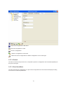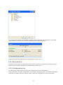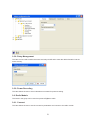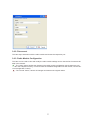
1
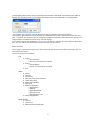
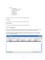
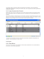
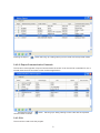
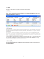
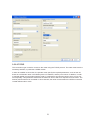
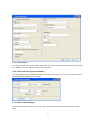
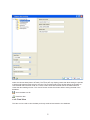
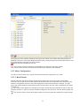
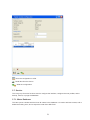
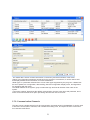
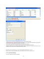
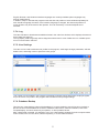
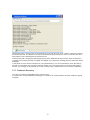
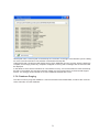
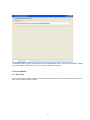
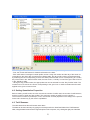
Unik
Software System for Parameterization of NiK Meters
User Manual
TABLE OF CONTENTS
1. INTRODUCTION 3
2. OVERVIEW 3
2.1.
2.2.
Purpose Required Operating System, PC, and Accessories 3. SOFTWARE FEATURES 3.1.
User Interface Functions
3.2.
Starting the Program 3.3.
Logging In 3.4.
File 3.4.1. Import 3.4.1.1. Meter Import 3.4.1.2. Communication Channel Import 3.4.2. Export
3.4.2.1. Meter Export 3.4.2.2. Communication Channel Export 3.4.3. Logging Out
3.5.
Meter
3.5.1. Select
3.5.2. Connect 3.5.2.1 COM Port
3.5.2.2 TCP/IP 3.5.3. Disconnect 3.5.4. Date and Time Synchronization 3.5.5. Reading Data from the Meter 3.5.6. Viewing Data 3.5.7. Meter Configuration 3.5.7.1. Most Recent 3.5.7.2. Default 3.5.7.3. Read from Meter 3.5.7.4. Read from File 3.5.7.5. Configurations List 3.5.8. Relay Management 3.5.9. POWER RECORDING 3.6.
Radio Module 3.6.1. Connect 3.6.2. Disconnect 3.6.3. Radio Module Configuration
3.7.
Service 3.7.1. Meter Database
3.7.2. Communication Channels 3.7.3. Interface Settings
3.7.4. Log 3.7.5. User Settings 3.7.6. Database Backup 3.7.7. Database Recovery 3.7.8. Database Purging 4. Pricing Model 4.1.
4.2.
4.3.
4.4.
4.5.
4.6.
3
4
4
4
4
4
6
6
6
7
7
7
8
8
9
9
9
9
10
11
11
11
12
13
13
14
14
15
15
16
16
16
16
17
17
18
18
19
20
21
21
21
22
23
24
Overview Setting Quantitative Properties Tariff Seasons
Holidays Week Profiles Day Profiles 24
25
25
26
26
26
2
1. INTRODUCTION
This Manual is intended for the specialists of metering equipment departments of energy companies. It
provides an overview of the UNIK software package functionality and the information required for configuration and programming of NIK 2102, NIK 2104, NIK 2303 and NIK 2305 multifunctional power meters, as
well as for local and remote reading of the measurement data. Access to the functions of UNIK software
package is controlled by a logical program control module, which provides a high level of security and
safety by forming a multi-level system of access privileges to various user (operator) groups.
The main functions of the software package are divided into several groups:
• Configuration: forming, programming, or reading the configuration
• Reading: reading and displaying the measurement data
• Database management: formation and operation of the database.
• Operator management: formation and management of operator access privileges and passwords.
2. OVERVIEW
2.1. Purpose
The UNIK package is a software application for NIK 2102, NIK 2104, NIK 2303 and NIK 2305 multifunctional electricity meters, designed to manage two types of meter data:
• Configuration parameters determining the meter configuration: they can be programmed and read, with
the software checking the compatibility of the parameters.
• Scan data (measurement data produced by the meter; these are read-only).
The software allows loading certain control commands into the meter (locally or remotely), such as engaging or disengaging a consumer relay, etc.
The program manages the configuration parameters database and stores the configuration and measurement data in the database.
The software application, containing multiple configurations and measurement data from various meters,
can only be used by one operator at a time. The operator interface makes the software easy and convenient to use.
The software supports various ways for communication with the meter:
• direct connection (null modem)
• modem connection (AT modem)
• TCP/IP link
• dial-up connection
• callback connection
• ZigBee connection
The main functions of UNIK software package are as follows:
• Operator management: access privileges and passwords
3
• Configuration management
• Meter control
• Data reading
• Radio module configuration
• Meter import/export
• Communication channel import/export
• Displaying and printing the measurement data
• Database management, including database purging.
The software allows the operator to configure a meter, read its data, and create configurations which may
be saved and loaded to the meters later as needed.
2.2. Required Operating System, PC, and Accessories
PC (minimum configuration): desktop or laptop, 533 MHz, 128 MB RAM, 1.2 GB disk space, display resolution 1024*768.
Operating system: The software program supports Windows XP, Windows 2000, and Windows Vista.
Installation: automatic.
Available interface languages: English, Russian, Ukrainian.
Database: no licenses required
Modem: any HAYES-compatible.
Optical Probes: OP-200, OK5.X (or any optical probes with USB-COM (FTDI) or PL2303 converters).
3. SOFTWARE FEATURES
3.1. Operator Interface Functions
UNIK operator interface is analogous to that of the standard single document interface (SDI) applications.
For example, the user may switch between fields within a window using the mouse or the keyboard; the
configuration elements are selected by a single mouse click, the transitions within the window are made
by a mouse click or TAB key, etc.
Each interface window contains the input fields for all necessary information related to the given element
of meter configuration. The input fields with a limited number of options use a dropdown list, from which
the necessary option can be selected with a mouse click, and the fields in which the value is selected
within a certain range use scroll buttons.
Where there are several options for a parameter and some space is needed for the text, the selection is
made using the option buttons.
The appropriate option can be selected from a “tree” of several possible options by switching to a new
window, where the user can select an appropriate option.
The options/parameters are activated/deactivated using radio buttons.
Some parameters are entered from the keyboard; where necessary, the input fields are filled with the
default values (standard configuration parameters).
In case of erroneous actions by the operator (wrong parameter input), the program displays an error message with a comment that helps correct the mistake.
3.2. Starting the Program
The program can be started in a standard way as any other Windows program.
After the application has started, the UNIK logo will appear on the screen.
3.3. Logging In
4
The first dialog with the user name and password input fields is displayed automatically when UNIK is
started. The operator can log in only if both parameters match those specified by an Administrator.
The program will close after 5 wrong attempts to enter the operator name and password.
The operator name field is not case sensitive; the password field is case sensitive and masks the entry
with “*” symbols. The operator name is used by the program to determine automatically the operator’s access privileges to software functions he or she can operate.
On the first occasion after installation, you can log in as “Admin” and with an empty password field; after
that, you can change the password and create accounts for other users.
Menu Structure
The program is operated using the menu bar in the upper part of the window. Each menu item may contain several sub-menus.
The menu structure is as follows:
• File
►
►
►
• Meter
►
►
►
►
►
►
►
►
►
Import
o Import Meters
o Import Communication Channels
Export
o Export Meters
o Export Communication Channels
Exit
Select
Connect
Disconnect
Date and Time Synchronization
Power Recording
Meter Data Reading
Data View
Meter Configuration
o Most Recent
o Default
o Read from Meter
o Read from File
o Configurations List
Relay Management
• Radio Module
► Connect
► Disconnect
► Radio Module Configuration
5
• Service
►
►
►
►
►
►
►
►
Meter Base
Communication Channels
Interface Settings
Log
User Settings
DB Backup
DB Recovery
DB Purging
The purpose of each menu item is described in the following sections.
3.4. File
This menu is used for Import/Export functions or to exit the program.
3.4.1. Import
This item can be used to import data from other software applications.
3.4.1.1. Import Meters
Selecting this option will open a dialog which can be used to find the necessary meter list file by browsing
the local PC and network resources. The operator may only select files with the .exd extension.
After the file is selected, a window listing the meters to be imported will be shown. If the meter number
matches one of the meters already existing in the database, it will be displayed on a gray background.
Such meter cannot be imported!
6
To import the meters, check all the meters to be imported in the “Selection” column and press the
“Import” button. The records containing the selected meters, their configurations and read-ing data will be
created in the database.
3.4.1.2. Import Communication Channels
Selecting this option will open a dialog which can be used to find the necessary communication channel
list file by browsing the local PC and network resources. The operator may only select files with the .exc
extension.
After the file is selected, a window listing the communication channels to be imported will be shown. If the
name of a communication channel matches one of the channels already existing in the database, it will be
displayed on a gray background. Such communication channel cannot be imported!
To import the communication channels, check all the communication channels to be imported in the
“Selection” column and press the “Import” button.
3.4.2. Export
3.4.2.1. Export Meters
This function is the opposite of Import Meters: it can be used to create files for one or several meters to
be sent later to other software applications.
7
Pressing the Export
button will bring up a dialog offering to save a file with the exported meters.
3.4.2.2. Export Communication Channels
This function is the opposite of Import Communication Channels: It can be used to create files for one or
several channels to be sent later to other software applications.
Pressing the Export
communication channels.
button will bring up a dialog offering to save a file with the exported
3.4.3. Exit
The menu item used to exit the program.
8
3.5. Meter
This group of options allows the operator to work with the meter functions.
3.5.1. Select
This menu item can be used to select a meter from the list for further operations with such meter (connection, viewing data and the most recent configuration). It can also be used to add a new meter to the
database or to delete/edit an existing one.
3.5.2. Connect
This menu item can be used to select and connect to a meter using one of the predefined communication
channels, with the ability to change the connection parameters, meter address in the system, user name
and password.
The “Auto meter detection” mode allows connecting to any of the sup-ported meter types upon proper
setting of the communication channel parameters, name, password, and, if necessary, the address in the
system. The meter type and number will be detected automatically; if the meter with the detected number
is not in the database, it will be added automatically.
It is also possible to set up the system to maintain the connection to the meter at certain intervals; if there
is no information exchange with the meter for a given period of time, the meter will be sent an energy
reading query, which will prevent disconnection due to timeout.
3.5.2.1 COM Port
This is a common connection type compatible with most communication devices connected to the computer via the COM port.
9
3.5.2.2 TCP/IP
This connection type is used to connect to the meter using the TCP/IP protocol. The meter must have the
necessary interface, in particular a GPRS modem.
In order to establish a connection, the operator must specify the required parameters, such as host address as a full domain name in the DNS system or IP address, and the port number. In addition, in order
to maintain stable communication with the meter, it is advised to set a timeout period, which can be chosen empirically. This parameter determines the maximum time to wait for a response from the meter. The
timeout period needs to be increased on slow channels; the value recommended for a GPRS connection
is 5000 milliseconds or more.
10
3.5.3. Disconnect
This item terminates the communication session with the meter, closes all communication ports and TCP/
IP or GPRS connections opened using the previous option.
3.5.4. Date and Time Synchronization
This item displays the time difference between the meter’s internal clock and computer system time and
allows adjusting this difference accordingly.
3.5.5. Meter Data Reading
The window displayed by selecting this menu item contains all commands required to read the meter
data.
11
The window is divided into several parts: the upper left part has a tree-like structure and can be used to
select the relevant data (data to be read). The lower part may display panels that allow setting the periods
of load profile data and total energy to be read. The remaining part of the window allows the operator to
view the data that have been read. The “Save” button saves the retrieved data in the data-base and
closes the data reading window. The “Cancel” button closes the window without saving the data in the
database.
- Save the data to a file.
- Read the data.
3.5.6. Data View
This item can be used to view the data previously retrieved and saved to the database.
12
The upper part of the window contains a list of types and names of the meters with data stored in the
database. The tree in the left part displays the description of the data with the retrieval date and time. The
data are displayed in the right part of the window.
button removes the data from the tree.
The “Save” button saves the changes to the database and closes the data view window.
The “Cancel” button closes the window without saving the changes to the database.
3.5.7. Meter Configuration
This item is used to read, view, change, and write the software configuration of a meter.
3.5.7.1. Most Recent
Selecting this item will open a window containing the data of the most recent meter configuration.
The tree in the left part of the window displays the date and time the configuration was created and the
names of configuration sections, with marks against the sections that have been changed. The right
part of the window displays several panels which can be used to view the meter configuration and make
changes to it.
- The “Apply” button applies the changes to the meter configuration (the changes are only made in the
computer memory; in order to write the modified configuration into the meter, use the “Write to Meter” button).
- The “Cancel” button cancels all changes made in the current panel and restores the original values.
13
- Export the configuration to MS Word.
- Save the configuration to a file.
- Print the configuration.
- Write the configuration to the meter.
- Make the current configuration the default configuration for this meter type.
3.5.7.2. Default
This item is similar to the previous one, except that it opens the configuration set as standard (default) for
the given meter type.
3.5.7.3. Read from Meter
This item reads the full configuration or a part of the configuration from the meters and displays a dialog
for the choice of relevant parameters.
14
The “Read” button initiates the configuration reading process, displaying the progress bar, the number
of bytes transferred and received, and the elapsed and estimated reading time.
Further actions with the configuration are as described in section 3.5.7.1.
3.5.7.4. Read from File
This item is used to open a configuration saved to a file, and opens a configuration file selection dialog.
Further actions with the configuration are as described in section 3.5.7.1.
3.5.7.5. Configurations List
This item can be used to view all recent meter configurations stored in the database.
Using this function, the meter configurations can be viewed, exported to Word, and saved to files without
connection to a meter, and thus cannot be used to modify the configuration or write it to the meter.
15
3.5.8. Relay Management
This item can be used to switch the meter load relay On/Off and to enter the debt information into the
meter memory.
3.5.9. Power Recording
This item allows the user to send a broadcast command for power recording.
3.6. Radio Module
The items in this group can be used to operate a ZigBee module.
3.6.1. Connect
This item allows the user to set the connection parameters and connect to the radio module.
16
3.6.2. Disconnect
This item stops interaction with the radio module and closes the respective port.
3.6.3. Radio Module Configuration
This item can be used to view and modify the radio module settings and to view the list of meters available in the network.
- The “Apply” button applies the changes to the radio module configuration (the changes are only
made in the computer memory; in order to write the modified configuration into the device, use the “Record Configuration” button).
- The “Cancel” button, cancels all changes and restores the original values.
17
- Save the configuration to a file.
- Read data from the device.
- Write the configuration.
3.7. Service
This is a group of service functions used to configure the interface, configure the user profiles, and to
backup, restore, or purge the database.
3.7.1. Meter Database
This item opens a window with the list of all meters in the database. It is used to add new meters, edit or
delete the existing ones, and to export the meter list to MS Excel.
18
Meter editing window:
The “Meter data” section contains information on the factory and serial numbers of the meter.
“Name” is an information parameter introduced for the operator’s convenience; it can be used to add
and display additional text information for meter identification.
“Meter type” is a parameter selected from a list of meter types supported by the pro-gram. It determines
the set of patterns for configuration, data reading, data and configuration display forms, and algorithms
for operations with the meter.
The “Meter address in the system” group contains the high and low ad-dresses of the meter in the
system.
“Connection settings” determines the default communication channel, user name and password, and a
meter connection maintenance option preventing disconnection due to tim-eout.
3.7.2. Communication Channels
This item opens a window with a list of all communication channels stored in the database. It can be used
to add new communication channels, edit or delete the existing ones, and export the list of communication channels to MS Excel.
19
Communication channel editing window:
“Channel name” is a unique informational name of a communication channel.
“Communication type” is a parameter selected from the list of connection types supported by the program.
It determines the set of additional connection parameters.
“Port” is the communication port assigned to the communication device.
“Connection speed” is the connection speed supported by the communication device.
“Timeout (milliseconds)” is the period during which the program will wait for a reply from the device. If this
parameter is not set, the value of 1000 milliseconds is used.
Depending on the connection type, there may be additional parameters, such as:
dial-up number, modem initialization string, host address (for a TCP/IP connection), etc.
3.7.3. Interface Settings
This item changes the interface language.
20
English, Russian, and Ukrainian interface languages are currently available (other languages may
also be implemented).
In addition, keep in mind that the program saves the size and position of some windows separately for
each interface language; therefore, if the interface language is changed, the sizes and positions of
some windows may be unusual for the operator. This can be fixed by a one-time adjustment of
windows.
3.7.4. Log
This item activates or deactivates an additional area in the main form window, which displays the external
device data exchange log.
The log display mode is typically used to diagnose malfunctions in case of data errors or unstable operation of communication channels.
3.7.5. User Settings
This item can be used to add new user profiles to the program, set/change the login passwords, edit and
delete users, and assign users to specific access groups.
The number of user profiles in the program is practically unlimited, which allows each employee (operator) to have their own profile in the program and individual access privilege settings.
3.7.6. Database Backup
This item can create backup copies of the database. It is recommended to use this function regularly to
prevent the loss of the database as a result of hardware malfunctions, malicious software, loss of the
computer/laptop, erroneous actions by an operator, or other possible causes.
After a backup file is created, it is advised to copy it to a data medium separate from the computer where
it was created, such as a CD, DVD, network repository, or a removable hard drive.
21
“Backup file name” is the full path to the backup file. If the file does not exist, it will be created; an existing
file will be replaced. The button to the right of the filename opens a dialog for more convenient and errorfree selection of the desired path for the backup file.
Under the file path, the program will display the log of the database backup process. After the backup is
complete, a line saying “Backup complete” will appear in the log and a message with the same text will be
displayed.
In the absence of the above indications of a successful backup, it is recommended to check the backup
file path; if the problem has not been resolved, please copy the log and send it to the technical support
service. It is strongly recommended not to use a backup copy created with errors to restore a database!
3.7.7. Database Recovery
This item can restore the database from a backup copy.
It is used if the working database is damaged, or needs to be moved/copied to another desktop or laptop
computer.
22
“Backup file name” is the full path to the backup file. The button to the right of the filename opens a dialog
for more convenient and error-free selection of the desired backup file.
Under the file path, the program will display the log of the database recovery process. After the backup is
complete, a line saying “Recovery complete” will appear in the log and a message with the same text will
be displayed.
In the absence of the above indications of a successful recovery, it is recommended to check the backup
file path; if the problem has not been resolved, please copy the log and send it to the technical support
service. It is strongly recommended not to use a database restored with errors!
3.7.8. Database Purging
This item is used to purge the database. It removes all meters and related data, as well as the communication channels, from the database.
23
The database will be purged after a backup file of the database is made. It is not recommended to disable
the backup option, as it is the only way to restore the data after the purge.
4. Pricing Model
4.1. Overview
During the parameterization process, all tariff time zones are entered into the meters: tariff seasons, holidays, week profiles, and day profiles.
24
The tariff applied at a certain moment in time can be determined by some simple calculations:
- First, the current tariff season is determined based on the date.
- Each tariff season is assigned a week profile number. Using this number and the day of the week corresponding to the given date, as well as the holidays table, the day profile number can be determined
by selecting the row corresponding to the active week profile and the column corresponding to a certain
day of the week in the “Week Profiles” table; the last column, “Holiday” is used if the given date is found
in the “Holidays” table.
- Having the day profile number, the appropriate row can be selected from the “Day Profiles” table. The
number in this row and in the column corresponding to the given hour or half-hour determines the tariff
applied at the given moment in time.
4.2. Setting Quantitative Properties
Before creating a tariff model, the user must set the number of tariffs used, the number of tariff seasons,
and the number of week and day profiles. The maximum number of tariffs in use is typically 4.
The maximum number of profiles (as, in fact, the number of tariffs) depends on the design of the specific
meter and is limited only by the meter’s capabilities.
4.3. Tariff Seasons
The table determines the tariff season start dates.
The date can be set in two ways: by typing it on the keyboard in the “Start Date” field of the “Tariff Seasons”
table, using the date format set in the regional options of the computer, or by clicking the right part of the field
25
with the mouse and selecting the desired date from the calendar. Some limitations apply to the
contents of the table:
- The first date must be the same as the beginning of the calendar year, i.e. January 1.
- All further dates must be entered in ascending order.
- All rows of the table must be filled, and the week number field must be greater than 0 and less than or
equal to the value set in section 4.2.
If one of the above conditions is not met, the invalid record in the table is highlighted in red, and the
model cannot be saved.
4.4. Holidays
This table specifies the holidays.
The date can be set in two ways: by typing it on the keyboard in the “Date” field of the “Holidays” table,
using the date format set in the regional options of the computer, or by click-ing the right part of the field
with the mouse and selecting the desired date from the calendar.
The number of records is limited to 30. No other restrictions apply to this table.
4.5. Week Profiles
This table determines the week profiles and consists of 9 columns: the first column is filled automatically
and contains the profile number, the 7 columns correspond to the days of the week, and the last column
corresponds to a holiday. The table is filled with numbers corresponding to the day profile number.
All cells of the table must be filled with values greater than 0 and less than or equal to the number of day
profiles. If this condition is not met, the invalid record in the table is highlighted in red, and the model cannot be saved.
4.6. Day Profiles
This table is an intuitive and convenient way to set and edit the day profiles.
The table is divided into 24 columns representing 24 hours of the day. The number of rows in the table
corresponds to the number of day profiles set as described in section 4.2. Each cell of the table contains
the number of the tariff to be applied at the given time of the day for the given profile. For better visual
representation, the tariff numbers 1 to 4 are marked with the corresponding cell colors:
0 – gray (no tariff defined)
1 – green
2 – blue
3 – red
4 – olive
Each day profile may contain up to 12 tariff time zones, with the transition times between them divisible
by 30 minutes; if the tariff change is not at a round hour, the respective cell is split in two halves, each
half representing a 30-minute period and indicating the tariff applied during that period with a number and
color.
There are two ways of setting the tariff time zones:
1. The boundaries between the zones can be moved to the right or to the left, making the zone larger or
smaller, respectively. If the user attempts to make the last (rightmost) zone shorter, it will be automatically
divided into two zones, and the tariff model will remain valid. If the number of zones reaches the maximum possible value (12 in our case), the size of the last zone cannot be reduced. While expanding any of
the zones except for the last one, the expanding zone may shift the next zone to the right and displace it.
The tariff number of the zone can be set by double clicking the zone;
26
this will increase the tariff number by 1, and as the tariff number exceeds the maximum possible value,
the tariff number will be changed to 1. Another way to set the tariff number is to do a right click and
choose “Zone settings” in the pop-up menu.
2. The user can switch between zones using the ←, ↑, →, and ↓ keys on the keyboard; ← and → keys
allow switching between the zones within the day profile, while ↑ and ↓ keys allow switching between profiles. Pressing the ← and → keys while holding down the Ctrl key expand and reduce the selected tariff
zone, respectively, whereas ↑ and ↓ keys pressed while holding down the Ctrl key increase or decrease
the number of the tariff applied in the selected tariff zone, respectively.
This allows creating, deleting, and editing the day profiles in an easy and intuitive way.
27