1
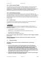
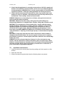
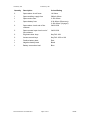
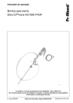
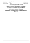
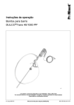
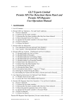
Created by: GG
Checked by: . JBJ
Approved by:JBJ
Control Equipment Limited
96 Zone 40-Character Discovery Panel,
32 Zone Voyager Panel
and Integra Network Repeater
Installation Manual
1. List Of Contents
1. List Of Contents .......................................................................................................1
2. List Of Figures..........................................................................................................2
3. Introduction ..............................................................................................................3
4. Scope .......................................................................................................................3
5. Overview of Installation ............................................................................................4
6. General Description .................................................................................................5
6.1 32/96 Zone Discovery Panel Description .........................................................5
6.1.1 BAQ140T24 PSU .....................................................................................5
6.1.2 A1686 P.S.E. Control Board.....................................................................5
6.1.3 A1579 Motherboard..................................................................................5
6.1.4 A1585 Loop Card .....................................................................................5
6.1.5 A1580 Display Board (32 Zone) ...............................................................6
6.1.6 A1687 Display Board (96 Zone) ...............................................................6
6.1.7 A1619 Interface Board..............................................................................6
6.1.8 A1620 Network Interface ..........................................................................6
6.1.9 A1599 Printer............................................................................................6
6.2 32 Zone Voyager Panel and Integra Network Repeater Description................7
6.2.1 C1675 2.5A P.S.E. ...................................................................................7
6.2.2 A1638 Motherboard..................................................................................7
6.2.3 A1636 Loop Card .....................................................................................7
6.2.4 A1637 Display Board................................................................................7
6.2.5 A1619 Interface Board..............................................................................8
6.2.6 A1620 Network Interface ..........................................................................8
6.2.7 A1599 Printer............................................................................................8
7. Installation ................................................................................................................8
7.1 Electrical Safety................................................................................................8
7.2 Installation Instructions .....................................................................................9
7.2.1 32/96 Zone, 40 character Discovery Panel Installation Instructions.......11
7.2.2 32 Zone 40-Character Voyager Panel Installation Instructions ..............13
7.3 Installation And Connection Of The A1619 Repeater Interface......................15
7.4 Installation And Connection Of The A1619 Input/Output Interface.................16
7.5 Installation And Connection Of The A1620 Network Interface .......................17
8. 32/96 Zone, 40 character Discovery Motherboard Features..................................18
9. 32/96 Zone, 40 character Discovery Power Supply Features And Connections ...19
10. 32 Zone, 40 character Voyager Motherboard Features .......................................20
11. 32/96 Zone, 40 character Voyager Power Supply Features And Connections....21
Document Number: DV40INS Rev 1
Page 1 of 31
18/2/08
Created by: GG
Checked by: JBJ
12. Circuit Connection Details....................................................................................22
12.1 Auxiliary Supply ..............................................................................................22
12.2 Use Of Auxiliary Outputs ................................................................................22
12.3 Use Of Auxiliary Inputs ...................................................................................23
12.4 Alarm Circuits .................................................................................................24
APPENDIX A Glossary of Terms ...............................................................................25
APPENDIX B 32/96 Zone, 40 character Discovery Mechanical And Environmental
Specification 26
APPENDIX C 32 Zone, 40-Character Voyager Mechanical And Environmental
Specification 28
APPENDIX D 32/96 Zone Discovery and 32 Zone Voyager Input and Output
Specification 29
2. List Of Figures
Figure 1 – 32/96 Zone Discovery panel main components..........................................5
Figure 2 – Voyager panel main components ...............................................................7
Figure 3 – Repeater connection diagram...................................................................15
Figure 4 – Expansion board connection diagram.......................................................16
Figure 5 – Network connection diagram ....................................................................17
Figure 6 - A1579 Discovery motherboard layout........................................................18
Figure 7 – 32/96 Zone, 40 character Discovery power supply layout ........................19
Figure 8 - A1638 32/96 Zone, 40 character Voyager motherboard layout.................20
Figure 9 – 32 Zone 40-Character Voyager power supply layout................................21
Figure 10 – Auxiliary fire contact connection details ..................................................22
Figure 11 – Auxiliary fault contact connection details ................................................22
Figure 12 – Monitored input circuit configuration .......................................................23
Figure 13 – Class change input circuit configuration .................................................23
Figure 14 – Alarm circuit configuration.......................................................................24
Document Number: DV40INS Rev1
Page 2 of 31
18/2/08
Created by: GG
Checked by: JBJ
3. Introduction
Thank you for purchasing this CEL Control Panel. This document contains all the
information necessary for the installation of the 32/96 Zone, 40 character Discovery
and 32 Zone, 40 character Voyager control panels and 32 zone, 40 character Integra
network repeater. These panels are functionally identical and differ only in the
number of loops and the physical packaging.
The Integra network repeater is a Voyager panel with no loop functionality. It is
designed to be used for access to a network when no loop devices are required. Any
features described for the Voyager that are not applicable to local loop devices are
available at the Integra network repeater.
This document is intended to provide guidance on installation methods only. These
recommended methods assume that the installers have received adequate training
covering the appropriate installation disciplines. This document does not attempt to
cover panel operation or functionality. This data can be found in the full manual
OMDV40_*.doc. Training courses dealing with system design, configuration,
commissioning and maintenance can be provided by Control Equipment Ltd.
The following supporting documentation is also available:
•
32/96 Zone, 40 character Discovery and Voyager Sales Literature
•
32/96 Zone 40 character Discovery and Voyager Panel Application Guide
•
32/96 Zone 40 character Discovery, Voyager and Integra User Manual
•
Wiring Recommendations
•
PC-based Software Programming Guide
•
Battery Calculation Spreadsheet
•
A1535 8 Way Output Board Application, Installation and Commissioning
Manual
•
A1536 8 Way Alarm Board Application, Installation and Commissioning
Manual
•
Repeater Application, Installation and Commissioning Manual
•
Outstation Installation and Commissioning Manual
•
32/96 Zone 40 character Discovery Panel, 32 zone, 40 character Voyager
Panel and Integra Network Repeater Installation, Commissioning and
Maintenance Manual.
4. Scope
This manual applies to all current 32 Zone Voyager and 32/96 Zone Discovery 40
character panels.
The product supports user programmed device location messages up to 40
characters in length. These are displayed as part of the event messages on the panel
LCD. The panel LCD is capable of displaying one event at a time.
Document Number: DV40INS Rev1
Page 3 of 31
18/2/08
Created by: GG
Checked by: JBJ
5. Overview of Installation
This section lists the steps that are taken in installing a 32/96 Zone, 40 character
Discovery or Voyager system.
1
2
3
Install all field wiring and equipment
•
The designers will have produced installations drawings detailing the location
and type of loop/field devices to be installed along with locations for the
control equipment. All cabling requirements will be detailed on these
drawings.
•
Refer to the Installation Instructions in section 7.2
•
Refer to the field device installation manuals
Install the panel
•
Refer to the installation instructions in section 7.
•
Do not connect the field equipment at this stage.
•
Disable networking at this stage.
Connect any repeaters (if applicable)
•
Refer to Installation And Connection Of The A1619 Repeater Interface in
section 7.3 and the repeater installation and commissioning manual.
Document Number: DV40INS Rev1
Page 4 of 31
18/2/08
Created by: GG
Checked by: JBJ
6. General Description
The panels are housed in a single metal enclosure with a polyester membrane giving
user controls and indications. The standby batteries are housed within the panel
enclosure.
6.1
32/96 Zone Discovery Panel Description
The panel consists of the modules shown in Figure 1. One loop card is fitted for each
loop that is connected to the panel. The Discovery drives a maximum of four loops of
devices.
A1579 MOTHERBOARD (2500143)
UP TO 4 OFF A1585
LOOP CARD (2500130)
A1686
PSE
CONTROL
BOARD
A1584
PSE
CONTROL
BOARD
(2500035)
BAQ140T24
PSE
XP
150W-30-7 PSU
A1619 I/O INTERFACE (OPTIONAL 2500162)
A1619 REPEATER INTERFACE (OPTIONAL 2500162)
OR A1620 NETWORK INTERFACE (OPTIONAL 2500163)
A1580 DISPLAY BOARD (2500144)
A1687 DISPLAY BOARD
A1599 PRINTER (2500107)
Figure 1 – 32/96 Zone Discovery panel main components
6.1.1 BAQ140T24 PSU
The Bentel BAQ140T24 is a 5 Amp switch mode PSU providing a nominal 27V
(temperature compensated) supply to the A1686 control board.
6.1.2 A1686 P.S.E. Control Board
The A1686 carries out the power supply monitoring and battery charger functions.
6.1.3 A1579 Motherboard
Provides all the field terminations, internal interfaces for up to 4 off plug-in loop cards;
connections for an A1619 interface for expansion I/O communication; connections for
an A1619 repeater interface or A1620 Network card; and connections to the main
display. The CPU and main memory locations are accommodated on this board.
6.1.4 A1585 Loop Card
This provides communications to the loop devices. The card provides short circuit
protection of both ends of the loop. The loop field wiring is terminated on the A1579.
Document Number: DV40INS Rev1
Page 5 of 31
18/2/08
Created by: GG
Checked by: JBJ
6.1.5 A1580 Display Board (32 Zone)
Provides visible indications and user switches, access to which is controlled by a
keyswitch. The board connects to the motherboard through a 50-way ribbon cable.
6.1.6 A1687 Display Board (96 Zone)
Provides visible indications and user switches, access to which is controlled by a
keyswitch. The board connects to the motherboard through a 50-way ribbon cable.
6.1.7 A1619 Interface Board
This optional plug-in board provides an RS485 capability for communication with
repeaters and expansion I/O boards. Up to two interfaces can be fitted to the
motherboard; one interface is dedicated to repeater communications, the second for
expansion I/O. If a network card is fitted this includes a repeater interface and
removes the requirement for an A1619 for communication with repeaters.
6.1.8 A1620 Network Interface
This optional plug-in board provides communication with other Discovery and
Voyager panels. The board plugs into the repeater interface sockets and provides
both repeater output communications and the network output. An A1619 is not
required for repeater communications if the A1620 is fitted.
6.1.9 A1599 Printer
The optional 24-column printer mounts on the outer door. Power and data are
supplied via a 16-way ribbon cable from the display board.
Document Number: DV40INS Rev1
Page 6 of 31
18/2/08
Created by: GG
6.2
Checked by: JBJ
32 Zone Voyager Panel and Integra Network Repeater Description
The panel consists of the modules shown in Figure 2. The driver circuit for loop 1 is
contained on the motherboard. The second loop is provided on a plug in loop card.
The 32 zone Voyager drives a maximum of two loops of devices.
CHASSIS
C1541 PSE (2500188)
A1638 MOTHERBOARD (2500905)
A1669
A1636 LOOP
LOOP CARD
CARD [2500145]
(2500903)
A1637 DISPLAY BOARD (2500907)
A1619 I/O INTERFACE (OPTIONAL 2500162)
A1619 REPEATER INTERFACE (OPTIONAL 2500162)
OR A1620 NETWORK INTERFACE (OPTIONAL 2500163)
A1599 PRINTER (2500107)
Figure 2 – Voyager panel main components
6.2.1 C1675 2.5A P.S.E.
The C1675 is a 2.5A switch mode p.s.e. which provides the power for the panel and
rechargeable battery.
6.2.2 A1638 Motherboard
Provides all the field terminations; an internal interface for one plug-in loop card;
connections for an A1619 interface for expansion I/O communication; connections for
an A1619 repeater interface or A1620 Network card; and connections to main
display. The CPU and main memory locations are accommodated on this board.
6.2.3 A1636 Loop Card
This provides communications to the second loop of devices. The card provides short
circuit protection of both ends of the loop. The loop field wiring is terminated on the
A1638.
6.2.4 A1637 Display Board
Provides visible indications and user switches, access to which is controlled by a
keyswitch. The board connects to the motherboard through a 50-way ribbon cable.
Document Number: DV40INS Rev1
Page 7 of 31
18/2/08
Created by: GG
Checked by: JBJ
6.2.5 A1619 Interface Board
This optional plug-in board provides an RS485 capability for communication with
repeaters and expansion I/O boards. Up to two interfaces can be fitted to the
motherboard; one interface is dedicated to repeater communications, the second for
expansion I/O. If a network card is fitted this includes a repeater interface and
removes the requirement for an A1619 for communication with repeaters.
6.2.6 A1620 Network Interface
This optional plug-in board provides communication with other 32/96 Zone, 40
character Discovery and 32 zone, 40 character Voyager panels. The board plugs into
the repeater interface sockets and provides both repeater output communications
and the network output. An A1619 is not required for repeater communications if the
A1620 is fitted.
6.2.7 A1599 Printer
The optional 24-column printer mounts on the outer door. Power and data are
supplied via a 16-way ribbon cable from the display board.
7. Installation
The control panel must be installed by competent engineers familiar with the
installation of fire detection systems. In addition, it is recommended to refer to the
following information:
•
Current edition of the IEE wiring regulations.
•
BS5839 Part 1 or the installation standards for the relevant country.
•
Any specific site requirements.
•
Apollo field device installation instructions.
Note: The mains supply cable should be a minimum of 1mm2 copper controlled
by a 5A fuse.
Note: An appropriate disconnect device shall be provided as part of the
building installation.
7.1
Electrical Safety
WARNING: Please read this section completely before commencing
installation.
1. Prior to handling any part of the control panel, ensure that adequate
precautions are taken against static damage to the sensitive electronic
components on the control board. You should discharge any static
electricity you may have accumulated by touching a convenient earthed
object, e.g. an unpainted copper radiator pipe or the enclosure earth. You
should repeat the process at regular intervals during the handling process,
especially if you are required to walk over carpets.
2. Check that the panel has been mounted at least 2 metres away from pager
systems or any other transmitting equipment.
Document Number: DV40INS Rev1
Page 8 of 31
18/2/08
Created by: GG
Checked by: JBJ
3. Check that the equipment is correctly connected to a 230V AC supply and
earthed. All installation work should be carried out in accordance with the
recommendations of BS5839 Part 1 and the current edition of the IEE wiring
regulations (BS7671: 1992) by suitably qualified and trained personnel.
4. Check that the control panel is located in a clean, dry position that is not
subject to shock or vibration. The temperature must not drop below 0°C or
exceed 40°C. The humidity should not exceed 95%.
DANGER: Batteries are electrically live at all times, take great care never to
short circuit the battery terminals.
WARNING: Batteries are often heavy, take great care when lifting and
transporting batteries. For weights above 24 kilos, lifting aids should be used.
WARNING. Do not attempt to remove battery lid or tamper with the battery
internal workings. Electrolyte is a highly corrosive substance, and presents
significant danger to yourself and to anything else it touches. In case of
accidental skin or eye contact, flush the affected area with plenty of clean,
fresh water and SEEK IMMEDIATE MEDICAL ATTENTION. VRLA batteries are
“low maintenance” requiring no electrolyte top-up or measurement of specific
gravity.
WARNING. If required, clean the case with a cloth that has been soaked or
dampened with distilled water. Do not use organic solvents (such as petrol,
paint thinner, benzene or mineral spirits) and other materials can substantially
weaken the case.
DANGER. Do not incinerate batteries. If placed in a fire, the batteries may
rupture, with the potential to release hazardous gases and electrolyte. VRLA
batteries contain substances harmful to the environment. Exhausted batteries
must be recycled. Return them to the battery manufacturer or take them to
your Council tip for appropriate disposal.
7.2
Installation Instructions
1. Carefully remove the control panel from the packing and lie the panel on a flat
surface.
2. Open the outer door.
3. Locate the spares bag and check that the following items are present:
Document Number: DV40INS Rev1
Page 9 of 31
18/2/08
Created by: GG
Checked by: JBJ
Quantity
Description
Colour/Rating
2
Spare alarm circuit fuses
1A 20mm
1
Spare auxiliary supply fuse
500mA 20mm
1
Spare mains fuse
3.15A 20mm
1
Spare battery fuse
6.3A 20mm (Discovery)
3.15A 20mm (Voyager)
2
Spare alarm circuit end of line
resistors.
3k9 0.25W
5
Spare remote input circuit end of
line resistors.
3k9 0.25W
2
Engineers door keys
Key Ref.: 801
2
Access control keys
Key Ref.: 850 or 901
1
Positive battery lead
Red
1
Negative battery lead
Black
1
Battery connection lead
Blue
Document Number: DV40INS Rev1
Page 10 of 31
18/2/08
Created by: GG
Checked by: JBJ
7.2.1 32/96 Zone, 40 character Discovery Panel Installation Instructions
1. Remove the main ribbon cable from the display board header.
2. Remove the ribbon cable clamp on the door to release the cables. Fold the cable
into the backbox. Replace the ribbon clamp onto the door.
3. Remove the earth strap connecting the door and backbox by removing the nut
and washer on the door. Carefully note the arrangement and replace the nut and
washer.
4. Unscrew the hinge pin at the bottom of the door whilst supporting the door. Swing
the bottom of the door clear of the backbox and release the top of the door from
its hinge pin.
5. Carefully put the door on one side and replace the hinge pin in the backbox.
6. Remove the earth strap connecting the backbox and chassis by removing the nut
and washer on the chassis. Carefully note the arrangement and replace the nut
and washer.
7. Unscrew the two lower chassis screws and slacken the top two mounting screws.
8. Carefully lift the chassis upward to align the screw heads with the large holes in
the chassis keyholes and lift the chassis clear of the backbox.
9. Place the chassis carefully to one side.
10. Place the chassis and door into the carton. Store the carton in a safe place until
installation is complete.
11. Identify the three indented holes that are used to mount the enclosure.
12. Place the enclosure in the desired location and mark the position of the top
indented hole. Remove the enclosure and fit a suitable fixing to the wall. Hang the
enclosure from the top fixing point and ensure that it is level. Mark the locations of
the other two mounting holes.
13. Remove the enclosure from the wall and fit suitable fixings to the two remaining
mounting points. Fit the enclosure to the wall using all three mounting points.
14. Gland the mains power cable into one of the holes provided at the bottom of the
enclosure. To meet the European EMC directives it is essential that these are the
only entry points used for mains power.
15. Gland all field wiring in place ensuring that the cable conductors are of sufficient
length. Ensure that all conductors are clearly labelled.
16. Connect the earth drain wires of any field cabling to either of the 6 way earth
blocks positioned at the top of the backbox. Up to two drain wires may be
connected to each terminal.
17. Ensure that continuity of any cable shield is maintained around the loop. The
shield must only be connected to enclosure earth in the panel by using the earth
bars provided.
18. Connect the mains-in earth to the primary earth point on the backbox indicated in
Figure 7. This is the lower of the two earth studs by the mains entry hole labelled
.
19. Clear any dust and debris from the cabinet.
20. Reinstallation of the chassis is the reverse of removal. Ensure that all earth straps
are reconnected correctly.
Document Number: DV40INS Rev1
Page 11 of 31
18/2/08
Created by: GG
Checked by: JBJ
21. Connect the mains-in live to the mains terminal block on the power supply as
indicated in Figure 7.
22. Connect the mains-in neutral to the mains terminal block on the power supply as
indicated in Figure 7.
23. Replace the door, the refitting procedure is the reverse of removal. Ensure that
the earth strap and ribbon cable are reconnected correctly. Do not connect the
field wiring at this stage.
24. Remove the two screws securing each battery clamp and place the battery
clamps to one side.
25. Place the left battery into the bottom of the panel. The terminals should be
positioned to the left of the enclosure and the battery adjacent to the left side of
the backbox. This is shown in Figure 7.
26. Place the right battery into the bottom of the panel. The terminals should be
positioned to the right of the enclosure and the battery adjacent to the right side
of the backbox. This is shown in Figure 7.
27. Refit the battery clamps to secure the batteries in place. Take care not to short
the battery terminals with a screw driver.
28. Connect the black battery lead to one of the negative battery terminals on the
p.s.e. The position is shown in Figure 7. Push the connector on the other end of
the lead onto the negative (black) terminal of the left-hand battery.
29. Connect the red battery lead to one of the positive battery terminals on the p.s.e.
The position is shown in Figure 7. Push the connector on the other end of the
lead onto the positive (red) terminal of the right-hand battery.
30. Connect the blue battery lead between the positive (red) terminal of the left-hand
battery and the negative (black) terminal of the right-hand battery. Note that the
batteries will not power the panel until the mains supply is energised.
Document Number: DV40INS Rev1
Page 12 of 31
18/2/08
Created by: GG
Checked by: JBJ
7.2.2 32 Zone 40-Character Voyager Panel Installation Instructions
1. Remove the main ribbon cable from the motherboard header.
2. Disconnect the earth strap connecting the door and backbox at the spade
terminal on the door.
3. Unscrew the hinge pin at the bottom of the door whilst supporting the door. Swing
the bottom of the door clear of the backbox and release the top of the door from
its hinge pin.
4. Carefully put the door on one side and replace the hinge pin in the backbox.
5. Unscrew the two lower chassis screws and slacken the top two mounting screws.
6. Carefully lift the chassis upward to align the screw heads with the large holes in
the chassis keyholes. Lift the chassis clear of the upper screws and rest in the
bottom of the enclosure. Take care not to strain the wires which remain
connected to the backbox.
7. Disconnect the earth strap connecting the backbox and chassis at the earth bar.
The arrangement is shown in .Figure 9.
8. Disconnect the flying leads from the transformer to the mains terminal block and
earth bar.
9. Remove the chassis and place carefully to one side.
10. Place the chassis and door into the carton. Store the carton in a safe place until
installation is complete.
11. Identify the three indented holes that are used to mount the enclosure.
12. Place the enclosure in the desired location and mark the position of the top
indented hole. Remove the enclosure and fit a suitable fixing to the wall. Hang the
enclosure from the top fixing point and ensure that it is level. Mark the locations of
the other two mounting holes.
13. Remove the enclosure from the wall and fit suitable fixings to the two remaining
mounting points. Fit the enclosure to the wall using all three mounting points.
14. Gland all field wiring in place ensuring that the cable conductors are of sufficient
length. Ensure that all conductors are clearly labelled.
15. Connect the earth drain wires of the field cabling to the 8 way earth bar
positioned at the top of the backbox. Up to two drain wires may be connected to
each terminal.
16. Ensure that continuity of any cable shield is maintained around the loop. The
shield must only be connected to enclosure earth in the panel by using the earth
bars provided.
17. Connect the mains-in earth to the primary earth point on the backbox indicated in
Figure 9. This is the earth bar and is labelled
.
18. Clear any dust and debris from the cabinet.
19. Connect the mains-in live to the mains terminal block on the power supply as
indicated in Figure 9.
20. Connect the mains-in neutral to the mains terminal block on the power supply as
indicated in Figure 9.
Document Number: DV40INS Rev1
Page 13 of 31
18/2/08
Created by: GG
Checked by: JBJ
21. Attach the mains-in cable to the cable clamp by the mains terminal using the
cable tie supplied.
22. Reinstallation of the chassis is the reverse of removal. Reconnect all wires as
shown in Figure 9. Ensure no cables are trapped between the chassis and
backbox.
23. Replace the door, the refitting procedure is the reverse of removal. Ensure that
the earth strap and ribbon cable are reconnected correctly. Do not connect the
field wiring at this stage.
24. Place the left battery into the bottom of the panel. The terminals should be
positioned towards the centre of the enclosure and the battery adjacent to the left
side of the backbox.
25. Place the right battery into the bottom of the panel. The terminals should be
positioned towards the centre of the enclosure and the battery adjacent to the
right side of the backbox.
26. Connect the black battery lead to one of the negative battery terminals on the
p.s.e. The position is shown in Figure 9. Push the connector on the other end of
the lead onto the negative (black) terminal of the left-hand battery.
27. Connect the red battery lead to one of the positive battery terminals on the p.s.e.
The position is shown in Figure 9. Push the connector on the other end of the
lead onto the positive (red) terminal of the right-hand battery.
28. Connect the blue battery lead between the positive (red) terminal of the left-hand
battery and the negative (black) terminal of the right-hand battery. Note that the
batteries will not power the panel until the mains supply is energised.
Document Number: DV40INS Rev1
Page 14 of 31
18/2/08
Created by: GG
7.3
Checked by: JBJ
Installation And Connection Of The A1619 Repeater Interface
Discovery repeaters duplicate the panel indications and user controls at a location
remote from the main panel. Up to 14 repeaters can be connected to a single panel
using an RS485 serial connection. The panel requires an A1619 Discovery interface
module (part number 2500162) or an A1620 Discovery network interface module
(part number 2500163) to be fitted to the motherboard to communicate with
repeaters.
Warning: Observe anti-static precautions
1. Ensure that the main and standby supplies are disconnected
2. Connect the repeater RS485 wiring as shown in Figure 3.
Notes:
1. Use only RS485 shielded data cable.
2. Do not connect the cable shield to earth.
3. If the repeater is to be powered from the panel connect the 28V auxiliary output
from the motherboard to the A1575 repeater display. This is also shown in Figure
3.
NETWORK
A
REPEATER
B SCN A
B SCN A
I/O
B SCN FAULT
28V 0V
J3
J4
B/+
A/SCN
FIRST A1575
REPEATER DISPLAY
B/+
A/SCN
X3
FLT
24V
0V
B/+
J5
J6
A/SCN
A1619 INTERFACE BOARD FITTED
TO LEFT POSITION ON A1579
TO DRIVE REPEATERS
SUBSEQUENT A1575
REPEATER DISPLAY
B/+
A/SCN
USE PANEL SUPPLY
OR LOCAL PSE
FLT
24V
0V
Figure 3 – Repeater connection diagram
Document Number: DV40INS Rev1
Page 15 of 31
18/2/08
Created by: GG
7.4
Checked by: JBJ
Installation And Connection Of The A1619 Input/Output Interface
The Discovery and Voyager panels can be expanded by the use of the A1535 and
A1536 expansion boards. These are located in an expanded cabinet that has an
extra compartment dedicated to the expansion boards.
For full details of the expansion boards see the CEL documents A1535 Application,
Installation and Commissioning Guide and A1536 Application, Installation and
Commissioning Guide.
The panel requires an A1619 interface module (part number 2500162) fitted to the
motherboard to communicate with I/O boards. Note that if repeaters are fitted to the
panel two A1619 interfaces will be required, one for the repeater communication and
one for the I/O connection.
Warning: Observe anti-static precautions
1. Ensure that the main and standby supplies are disconnected.
2. Connect the I/O interface RS485 wiring as shown in Figure 4.
Notes:
1. Use only RS485 shielded data cable.
2. Do not connect the cable shield to earth.
3. If the I/O board is to be powered from the panel connect the 28V auxiliary
output from the motherboard to the expansion board power input. This is also
shown in Figure 4.
LEAVE SCREEN DISCONNECTED
AT EXPANSION BOARD END
MXMX+
MXMX+
0V
FIRST
A1535 OR A1536
EXPANSION BOARD
24V
NETWORK
REPEATER
I/O
MX-
A
B SCN A
B SCN A
B SCN FAULT
28V 0V
MX+
J3
J4
MXMX+
0V
SECOND
A1535 OR A1536
EXPANSION BOARD
24V
J5
J6
A1619 INTERFACE BOARD FITTED
TO RIGHT POSITION ON A1579
TO DRIVE EXPANSION BOARDS
Figure 4 – Expansion board connection diagram
Document Number: DV40INS Rev1
Page 16 of 31
18/2/08
Created by: GG
7.5
Checked by: JBJ
Installation And Connection Of The A1620 Network Interface
Warning: Observe anti-static precautions
1. Ensure that the main and standby supplies are disconnected.
2. Connect the network RS485 wiring as shown in Figure 5. A maximum of 15
active panels can be connected together in this way. Any number of panels
can be added as passive repeaters provided the total number of panels does
not exceed 32.
Notes:
1. Use only RS485 shielded data cable.
2. Do not connect the cable shield to earth.
TO NEXT PANEL
NETWORK
A
REPEATER
B SCN A
B SCN A
I/O
NETWORK
B SCN FAULT
28V 0V
A
J3
REPEATER
B SCN A
B SCN A
I/O
B SCN FAULT
J4
X3
X3
U5
J5
3
4
S1
2
J6
1
2
4
8
NETWORK
ADDRESS
S1
1
2
4
8
NETWORK
ADDRESS
J6
J1
U5
1
28V 0V
J3
J4
1
2
3
4
A1620 NETWORK INTERFACE
FITTED TO A1579 MOTHERBOARD
A1620 NETWORK INTERFACE
FITTED TO A1579 MOTHERBOARD
Figure 5 – Network connection diagram
4. Do not set the network node address on the A1620 NETWORK ADDRESS switch
- this is part of the commissioning activity.
Document Number: DV40INS Rev1
Page 17 of 31
18/2/08
Created by: GG
Checked by: JBJ
8. 32/96 Zone, 40 character Discovery Motherboard Features
Figure 6 illustrates the 32/96 Zone, 40 character Discovery motherboard features
referred to elsewhere in the documentation.
!
Field wiring
terminals
Lithium battery
NETWORK
REPEATER
B
B
A
SCN A
SCN A
LOOP 1
I/O
B
SCN CLASS
FAULT
EVAC.
NO P NC NO P NC NO
P NC
FAULT
FIRE 1
FIRE 2
SILENCE RESET 28V 0V
J3
LK2
+
ALM 2
O1+ O1- I1+ I1-
LOOP 2
O2+ O2- I2+ I2-
LOOP 3
LOOP 4
O3+ O3- I3+ I3-
O4+ O4- I4+ I4-
J4
B1
FS4
LINK LK2
TO ENABLE
EARTH FAULT
MONITORING
+
ALM 1
COMPUTER
INTERFACE
S3
DISABLE
SSD WRITE-ENABLE
1 2 3 4
S4
1
2
3
4
CONFIGURATION
SWITCHES
KEYBOARD
LK1
LOOP 1
LINK TO
DISABLE
DISPLAY
MONITOR
LOOP 2
J12
J13
LOOP 3
LOOP 4
J14
J15
J1
J5
J6
U2A
U4
U3
+
LK3
I2
BUZZER
DISABLE
S1
SYSTEM
FAULT RESET
S2
PROCESSOR
RESET
A1584 INTERFACE
28V 5V
0V
MF CF
1
J2
FID2
Figure 6 - A1579 Discovery motherboard layout
!
Lithium battery caution - danger of explosion if battery is incorrectly
replaced. Replace only with CR1620 3V or equivalent type recommended by the
manufacturer. Dispose of used batteries according to the manufacturer’s
instructions. Only trained service personnel should replace this battery.
Document Number: DV40INS Rev1
Page 18 of 31
18/2/08
Created by: GG
Checked by: JBJ
9. 32/96 Zone, 40 character Discovery Power Supply Features And
Connections
Figure 7 shows the layout of the Discovery panel power supply. The supply should
be earthed as illustrated.
Power supply status indicators:
OUTPUT OK
Output healthy
BATT/CHARGE FAULT
Battery or charger fault
EARTH FAULT
Short circuit between earth and field cabling
5/8V FAULT
5/8V supply fault
MAINS FAULT
Mains failed
End outer insulation close to PSE
and route earth connection back
to primary earth connection point
OUTPUT OK
Power output connector
to motherboard
BATT/CHARGE
FAULT
EARTH FAULT
Fit cable tie here to secure
incoming mains cable
Link fitted to select
5V output
Terminals not used
Battery fuse (6.3A)
5/8V FAULT
MAINS FAULT
E
AC IN
+
L
N
230V ~ 50/60Hz
TEST LAMPS
+
5V FIT
8V N/F
+
Charger voltage adjustment
OUTPUT OK
BATT/CHARGE
FAULT
EARTH FAULT
5/8V FAULT
MAINS FAULT
LK1
EARTH CAP
LK2
EARTH FLT
BAT + BAT -
TEST LAMPS
Battery terminals
Fix thermistor to battery lead
with cable tie
Do not fit links for
EARTH CAP or
EARTH FLT
Fit battery terminals towards
outside of enclosure
Incoming mains supply.
Fix to side of power supply with cable
ties
Connect mains in earth to primary
enclosure earth stud here
Connect chassis to enclosure
secondary earth stud here
Figure 7 – 32/96 Zone, 40 character Discovery power supply layout
Document Number: DV40INS Rev1
Page 19 of 31
18/2/08
Created by: GG
Checked by: JBJ
10. 32 Zone, 40 character Voyager Motherboard Features
Figure 8 illustrates the Voyager motherboard features referred to elsewhere in the
documentation.
LINK LK1 TO
ENABLE EARTH
FAULT MONITORING
Field wiring
terminals
NETWORK
REPEATER
I/O
TB3
TB4
TB5
TB6
TB7
TB8
TB9
TB10
TB11
TB12
TB13
TB14
TB15
TB16
TB17
TB2
A
B
SCN
A
B
SCN
A
B
SCN CLASS
EVAC.
SILENCE RESET 28V 0V
NO P
NC NO P
NC NO
P NC
FAULT
FIRE 1
FIRE 2
+
ALM 1
+
ALM 2
O1+ O1- I1+ I1- O2+ O2- I2+ I2LOOP 1
LOOP 2
KEYBOARD
LK1
4
2
3
J3
FS2
SPARE
1
J8
J5
!
J1
ALARM
1
RL4
J7
RL3
Lithium
battery
SWITCHES
U9
FS4
AUXILIARY
FS3
COMPUTER
INTERFACE
LP2
NET
SW3
SYSTEM
FAULT
ALARM 2
U14
J11
FS5
J6
J2
U32
U34
U16
BUZ1
U6
U8
LK3
BUZZER
DISABLE
S4
J12
S3
PROCESSOR RESET
ENABLE< >DISABLE
SSD WRITE - ENABLE
CEL A1638 ISSUE 1 27-06-2001
DC Power in connector [from PSE]
Figure 8 - A1638 32/96 Zone, 40 character Voyager motherboard layout
!
Lithium battery caution - danger of explosion if battery is incorrectly
replaced. Replace only with CR1620 3V or equivalent type recommended by the
manufacturer. Dispose of used batteries according to the manufacturer’s
instructions. Only trained service personnel should replace this battery.
Document Number: DV40INS Rev1
Page 20 of 31
18/2/08
Created by: GG
Checked by: JBJ
11. 32/96 Zone, 40 character Voyager Power Supply Features And
Connections
Figure 9 shows the layout of the Voyager panel power supply. The supply should be
earthed as illustrated.
Fit cable tie to retain
incoming mains cable
Fused mains
terminal block
230V AC Mains in
Brown PSU lead
Earth
leads
L
E
N
Blue PSU
lead
Brown
PSU lead
Blue
PSU lead
Earth
lead
Figure 9 – 32 Zone 40-Character Voyager power supply layout
Document Number: DV40INS Rev1
Page 21 of 31
18/2/08
Created by: GG
Checked by: JBJ
12. Circuit Connection Details
12.1
Auxiliary Supply
An auxiliary supply is available to power external field equipment from the panel. This
is nominally rated at 28V (24V for Voyager) The maximum load is 500mA, the output
is fused.
The auxiliary supply terminals are labelled 28V and 0V.
12.2
Use Of Auxiliary Outputs
Warning: The volt-free auxiliary relay contacts must not be used to directly
switch any voltage which exceeds 30VDC.
Auxiliary changeover contacts are provided which operate on fire and fault
conditions. There are two sets of auxiliary fire contacts. The configuration of the relay
contacts is shown in Figure 10.
3
2
1
NC
P
NO
FIRE 1 CONTACTS
NC
3
2
1
P
NO
TO FIELD EQUIPMENT
TO FIELD EQUIPMENT
TO FIELD EQUIPMENT
TO FIELD EQUIPMENT
TO FIELD EQUIPMENT
TO FIELD EQUIPMENT
FIRE 2 CONTACTS
CONTACTS SHOWN IN QUIESCENT CONDITION
Figure 10 – Auxiliary fire contact connection details
The single set of auxiliary fault contacts operate on any panel fault condition. This
output is failsafe and is active in a system fault, or if the system suffers failure of all
power supplies. The configuration of the relay contacts is shown in Figure 11.
1
2
3
NC
P
NO
TO FIELD EQUIPMENT
TO FIELD EQUIPMENT
TO FIELD EQUIPMENT
FAULT CONTACTS
CONTACTS SHOWN IN QUIESCENT CONDITION
Figure 11 – Auxiliary fault contact connection details
Document Number: DV40INS Rev1
Page 22 of 31
18/2/08
Created by: GG
12.3
Checked by: JBJ
Use Of Auxiliary Inputs
Auxiliary inputs are provided to allow remote operation of the following functions:
•
Fault (Discovery only)
•
Evacuate
•
Silence
•
Reset
Each input circuit is fully monitored for open and short circuit faults. To activate an
input a 680 ohm resistor should be connected across the input circuit by a normally
open switch contact. Two switches are shown in Figure 12 although there is no limit
to the number of switches.
IN P U T C IR C U IT
S W IT C H
S W IT C H
END OF
L IN E
3k9
680R
680R
IN P U T C IR C U IT
Figure 12 – Monitored input circuit configuration
Note: To prevent unauthorised operation of the systems all auxiliary inputs
must be operated by key-switches. The keys to these switches should be held
with the access control key.
Additionally there is a class change input. To activate the input a 680 ohm resistor
should be connected across the input circuit The panel does not display any
indication whilst this input is active. The connection diagram for the class change
input is shown in Figure 13.
IN P U T C IR C U IT
S W IT C H
S W IT C H
680R
680R
IN P U T C IR C U IT
Figure 13 – Class change input circuit configuration
Document Number: DV40INS Rev1
Page 23 of 31
18/2/08
Created by: GG
12.4
Checked by: JBJ
Alarm Circuits
The Discovery and Voyager panels have two alarm circuits, each rated at 1A. The
circuits are reverse polarity monitored for open and short circuit faults. To allow
monitoring all devices must be polarised. To prevent damage to the control panel
bells must also have a suppression diode fitted as shown in Figure 14. The circuit
must be terminated with a 3k9 end of line resistor.
ALARM CIRCUIT +
POLARISING
DIODE (E.G. 1N4002S)
END OF LINE
3k9
SUPPRESSION
DIODE (E.G. 1N4002S)
BELL
SOUNDER
ALARM CIRCUIT -
Figure 14 – Alarm circuit configuration
Document Number: DV40INS Rev1
Page 24 of 31
18/2/08
Created by: GG
Checked by: JBJ
APPENDIX A Glossary of Terms
A
Amp - unit of current.
Ac
Alternating Current
Ah
Amp hour – unit of capacity for standby batteries.
BGU
Break Glass Unit. Also know as manual call point.
Cause/effect
The relationship between programmable actions
and the events which cause those actions.
CIE
Control and indicating equipment (the control panel)
c/w
complete with
CPU
central processing unit
Dc
Direct Current
EMC
Electro-Magnetic Compatibility.
EOL
End Of Line resistor.
I/O
Input/output
LCD
Liquid Crystal Display. Alphanumeric display used
for textual information.
LED
Light Emitting Diode. Display indicator.
Local
cause/effect
Cause and effect where an event on a panel does
not cause an action on any other panel. (c.f.
network cause/effect)
MCP
Manual Call Point also know as BGU.
Network
cause/effect
Cause/effect where an event on one panel causes
an action on another panel (c.f. local cause/effect).
Network panel
A panel connected to another panel using the
Integra network card to create a larger system.
Node
One panel on a network system. Also called a
network node.
PC
Personal Computer.
PCB
Printed Circuit Board.
P.s.e.
Power Supply Equipment.
RS485
Serial communications standard used for
interconnection of equipment. It is commonly used
to refer to connections using this type of
communications.
Stand-alone
panel
A panel not connected to any other panel using the
Integra network card network
SLA
Sealed Lead Acid – type of standby battery.
V
Volt – unit of electrical potential.
Document Number: DV40INS Rev1
Page 25 of 31
18/2/08
Created by: GG
Checked by: JBJ
APPENDIX B 32/96 Zone, 40 character Discovery Mechanical And
Environmental Specification
Mechanical Specification
Size: Height:
Width:
Depth:
Weight excluding batteries:
480mm
410mm
160mm including lock and indented holes
15kg
Environmental Specification
Operating temperature:
-5ºC to 40ºC
Operating humidity:
5% to 95%
Mains Input Specification
Voltage:
Maximum Input Power:
Protection:
Cable requirements:
230V AC +10%/-15%
320VA
T3.15A anti-surge sand filled fuse
Minimum of 1mm2 copper controlled by a 5A
fuse.
Power Supply Output Specification
28V output:
25-28V @ 4A mains on
21-27V @ 4A mains failed
28V output protection:
Electronic current limiting
5V output:
4.7-5.4V @ 3A
5V output protection:
Electronic current limiting
Common fault output:
Open collector output labelled CF
Mains failed fault output:
Open collector output labelled MF
Document Number: DV40INS Rev1
Page 26 of 31
18/2/08
Created by: GG
Battery Specification
Battery charger output:
Maximum battery load:
Battery type:
Checked by: JBJ
Temperature compensated float charger 27.4V
±0.1V @20°C; maximum current 1.5A (limited
if 28V load greater than 3.5A).
5A
2 off 12V 12Ah sealed lead acid standby
battery
Battery size:
151mm x 98mm x 97.5mm
Battery circuit protection:
5A fast blow glass fuse
Mains failed fault battery current:
145mA
1 Loop panel:
170mA
2 Loop panel:
195mA
3 Loop panel:
220mA
4 Loop panel:
Mains failed alarm battery current:
260mA
1 Loop panel:
285mA
2 Loop panel:
310mA
3 Loop panel:
335mA
4 Loop panel:
Document Number: DV40INS Rev1
Page 27 of 31
18/2/08
Created by: GG
Checked by: JBJ
APPENDIX C 32 Zone, 40-Character Voyager Mechanical And
Environmental Specification
Mechanical Specification
Size: Height:
Width:
Depth:
Weight excluding batteries:
370mm
325mm
135mm including lock and indented holes
7.4kg
Environmental Specification
Operating temperature:
-5ºC to 40ºC
Operating humidity:
5% to 95%
Mains Input Specification
Voltage:
Maximum Input Power:
Protection:
Cable requirements:
230V AC +10%/-15%
207VA
T3.15A anti-surge sand filled fuse
Minimum of 1mm2 copper controlled by a 5A
fuse.
Power Supply Output Specification
24V output:
26.8V to 28.2V @ 2.5A mains on
21-26V @ 2.5A mains failed
24V output protection:
Electronic current limiting
Common fault output:
Open collector output labelled FAULT
Battery Specification
Battery charger output:
Maximum battery load:
Battery type:
float charger 26.8V to 28.2V @ 2.5A maximum
2.5A
2 off 12V 12Ah sealed lead acid standby
battery
Battery size:
151mm x 98mm x 97.5mm
Battery circuit protection:
3.15A fast blow glass fuse
Mains failed fault battery current:
1 Loop panel:
120mA
2 Loop panel:
140mA
Mains failed alarm battery current:
1 Loop panel:
255mA
2 Loop panel:
275mA
Document Number: DV40INS Rev1
Page 28 of 31
18/2/08
Created by: GG
Checked by: JBJ
APPENDIX D 32/96 Zone Discovery and 32 Zone Voyager Input and
Output Specification
Panel Input Specification
Remote Fault:
Remote Evacuate:
Remote Silence:
Remote Reset:
Class-change:
Input Protection:
Cable requirements:
Fully monitored circuit, 3k9 EOL, 680R active
Fully monitored circuit, 3k9 EOL, 680R active
Fully monitored circuit, 3k9 EOL, 680R active
Fully monitored circuit, 3k9 EOL, 680R active
Non- circuit, normally open, <50R active
Internal current limit to 1mA
No special requirements, total resistance must
be less than 50 ohms
Loop Output Specification
Loop 1 Terminals:
O1+ Loop out +ve
O1Loop out –ve
I1+
Loop return +ve
I1Loop return –ve
Loop 2 Terminals:
O2+ Loop out +ve
O2Loop out –ve
I2+
Loop return +ve
I2Loop return –ve
Loop 3 Terminals:
O3+ Loop out +ve
(Discovery only)
O3Loop out –ve
I3+
Loop return +ve
I3Loop return –ve
Loop 4 Terminals:
O4+ Loop out +ve
(Discovery only)
O4Loop out –ve
I4+
Loop return +ve
I4Loop return –ve
Maximum Current:
500mA per loop
Protection:
Negative leg isolation circuit for loop out and
loop in. Common positive leg fused at 650mA.
Communications:
Apollo Discovery/XP95 protocol
Pedestal voltage:
27.8V to 28.5V
Pulse voltage:
7.5V to 9V
Maximum points per loop:
126
Maximum number of zones: 32 total with no restriction on allocation to
loops
Document Number: DV40INS Rev1
Page 29 of 31
18/2/08
Created by: GG
Alarm Circuit Specification
Quantity:
Output Voltage (mains
operation):
Output Voltage (battery
operation):
Maximum Current:
Fault Monitoring:
Protection:
Cable requirements:
Checked by: JBJ
2
25-29V
21-27V
1A per circuit
Reverse polarity for open and short circuit
faults
1A fast blow glass fuse
No special requirements, 1A minimum current
rating. Minimum voltage at end of line must be
above sounding device minimum operating
voltage.
Auxiliary Supply Specification
Auxiliary supply (mains
25-29V
operation):
Auxiliary supply (battery
21V-27V
operation):
Maximum Current:
500mA
Fault Monitoring:
Monitored for fuse failure
Protection:
500mA fast blow glass fuse
Cable requirements:
No special requirements, 1A minimum current
rating. Minimum voltage at end of line must be
above sounding device minimum operating
voltage.
Repeater Output Specification
Number of repeaters:
1 to 14
Maximum repeater cable
2000m
length:
Communication protocol:
RS485 serial data 9600 baud
Protection:
Electronic current limited
Cable Type:
Single pair RS485 shielded cable (see below)
Input/Output Expansion Board Specification
Board types:
A1535 I/O board
Number of boards:
0 to 31
Maximum cable length:
Boards should be mounted within, or adjacent
to the panel enclosure
Communication protocol:
RS485 serial data 4800 baud
Protection:
Electronic current limited
Cable Type:
Document Number: DV40INS Rev1
Single pair RS485 shielded cable (see below)
Page 30 of 31
18/2/08
Created by: GG
Checked by: JBJ
Alarm Expansion Board Specification
Board type:
A1536 I/O board
Number of boards:
0 to 31
Maximum cable length:
Boards should be mounted within, or adjacent
to the panel enclosure
Communication protocol:
RS485 serial data 4800 baud
Protection:
Electronic current limited
Cable Type:
Single pair RS485 shielded cable (see below)
Network Output Specification
Number of nodes:
1 to 15
Maximum network cable
5000m
length:
Communication protocol:
RS485 serial data 9600 baud
Protection:
Electronic current limited
Cable Type:
Single pair RS485 shielded cable (see below)
RS485 Cable Specification
Generic Type:
Conductors:
Alpha cable:
Belden cable:
RS422/RS485 data cable.
Single pair plus screen.
3492C, 6222C, 6412 or equivalent
8102, 8132, 9841 or equivalent
Document Number: DV40INS Rev1
Page 31 of 31
18/2/08