1
2 CONTROLS & CONNECTIONS
2.1 FRONT PANEL LAYOUT
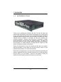
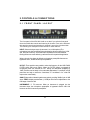
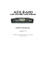
The front panel of the ADL 600 is laid out so that if you split the front panel
down the middle the controls and metering for channel 1 are on the left hand
side and the controls and metering for channel 2 are on the right hand side.
The following is a description of the controls for each channel:
INPUT: Selects the input source (Instrument, Line, or Microphone) The
microphone input has four different input impedance values to select from (1500,
900, 300 and 150 ohms). As the ADL 600’s impedance is lowered, different
filtering effects can result delivering a tailored sound for a particular application.
When using the Line input, the following microphone preamplifier features are
bypassed: +48V, -20dB PAD and input impedance.
HP FILT: Three position rotary switch to select the frequency for the HIGH PASS
FILTER (40Hz, 80Hz and 120Hz). When the FILTER switch is engaged all
frequencies below the selected HP FILT setting are attenuated (dropped) by
12dB. This filter can be handy in live and studio applications. For example, a high
pass filter can help to reduce the “boominess” or “muddiness” of a vocal and
improve the overall clarity.
GAIN: Eight-position industrial grade rotary switch providing 35dB of gain in 5dB
steps. TRIM: Variable potentiometer (+/-10dB) to offer fine trim adjustment to the
final stage of the ADL 600.
INSTRUMENT: ¼” TS connector. When an instrument is plugged into the
instrument input, the microphone preamplifier is bypassed and the ADL 600
becomes an active instrument preamplifier.
6