1
AR300 SERIES ROUTER
QUICK START GUIDE
S i m p ly c o n n e c t i n g t h e wo r l d
AR300 Series Router Quick Start Guide.
Document Number C613-04011-00 REV C.
Copyright © 2000-2001 Allied Telesyn International, Corp.
960 Stewart Drive, Suite B, Sunnyvale CA 94085-3912, USA.
All rights reserved. No part of this publication may be reproduced without
prior written permission from Allied Telesyn.
Allied Telesyn International, Corp. reserves the right to make changes in
specifications and other information contained in this document without prior
written notice. The information provided herein is subject to change without
notice. In no event shall Allied Telesyn be liable for any incidental, special,
indirect, or consequential damages whatsoever, including but not limited to
lost profits, arising out of or related to this manual or the information
contained herein, even if Allied Telesyn has been advised of, known, or should
have known, the possibility of such damages.
All trademarks are the property of their respective owners.
A R 3 0 0 R O U T E R Q U I C K S TA R T G U I D E
3
Contents
Introducing the AR300 Series Router .............. 4
Configuring ISDN ............................................ 13
Models in the AR300 Series ........................................................ 4
Configuring Basic Rate ISDN ................................................... 13
What Can the AR300 Do For You? ........................................... 4
Configuring Primary Rate ISDN .............................................. 14
About this Guide ............................................................................ 5
Configuring ISDN Dial on Demand ........................................ 16
Where to Find Safety and Statutory Information .................. 5
Configuring ISDN Bandwidth on Demand ........................... 16
Getting Connected ............................................ 6
Configuring an IP Network ............................. 17
Using Windows Terminal or Windows HyperTerminal
as the Console ......................................................................... 6
Before You Start ........................................................................... 17
Connecting to an Ethernet Hub or PC .................................... 8
Configuring IP .............................................................................. 18
Troubleshooting IP Configurations ......................................... 19
Connecting Telephones and Facsimile Machines .................... 8
Ordering ISDN in the USA and Canada .................................. 9
Configuring a Novell IPX Network ................ 20
Connecting to a Basic Rate ISDN Service ............................... 9
Before You Start ........................................................................... 20
Connecting to a Primary Rate ISDN Service .......................... 9
Configuring IPX ........................................................................... 21
Connecting to a Leased Line Circuit ...................................... 10
Troubleshooting IPX Configurations ...................................... 22
Connecting a Terminal or Modem .......................................... 10
Configuring IPX Dial on Demand ........................................... 23
Documentation and Tools CD-ROM .............. 12
Configuring Telephone Services ..................... 24
Using the CD-ROM .................................................................... 12
Before You Start ........................................................................... 25
Using AT-TFTP Server ................................................................ 12
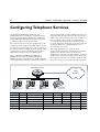
Configuring Telephony Services ............................................... 25
Troubleshooting PBX Configurations .................................... 27
4
A R 3 0 0 R O U T E R Q U I C K S TA RT G U I D E
Introducing the AR300 Series Router
Congratulations on purchasing an AR300 Series router—the
intelligent choice! No other solution will provide you with
more networking capabilities or more cost saving features.
supports advanced features that make it easy for your Internet
Service Provider to dynamically assign your Internet address
every time you surf the net.
This guide will introduce you to the AR300 router and guide
you through the most common uses and applications. Getting
started will not take long—most applications can be set up in
just a few minutes. If you have any questions about the AR300
router, contact your local distributor or reseller.
Connect You to the Office
Model
ISDN1
AR300L(S)
BRI S/T
-
1 (DB9 Female)
-
1
AR300(S)
BRI S/T
-
1 (DB9 Female)
2
1
Many small offices and home offices require fast and efficient
access to a central office, to check email, access a database or
download a file. The AR300 supports Windows®, Novell® and
Apple® Macintosh® systems. The intelligent bandwidth
management facility automatically opens more ISDN channels
when extra capacity is required, and closes them when traffic
levels reduce. Powerful firewall features protect against
unauthorised access, and break-in attempts can be logged for
later analysis. If your office LAN utilises private IP addresses not
registered on the Internet, the AR300 can translate these
private addresses to a single registered IP address for
communication across the Internet, saving you the time and
expense of assigning registered IP addresses to each device on
your LAN.
AR310(S)
BRI S/T
-
1 (DB9 Female)
4
1
Connect You to Other Trading Partners
AR320
-
-
2 (DB9 Male)
-
2
AR330
-
1
2 (DB9 Male)
-
2
AR350
-
1
2 (DB9 Male)
-
1
BRI S/T
1
2 (DB9 Male)
-
1
The AR300 allows small offices to communicate with other
trading partners using ISDN, leased line, Frame Relay or X.25
services. Information such as reports, quotes and orders can be
transferred between the two offices. The AR300 does not place
any limits on the number of network users, so it will continue
to support you as your business grows.
MODELS IN THE AR300 SERIES
The AR300 Series supports a wide range of network interfaces
so you can choose the network service that is right for you.
Number and Type of Interfaces
AR370(S)
Synchronous2
Asynchronous
Voice
Lan
AR370(U)
BRI U
1
2 (DB9 Male)
-
1
AR390
G.7033
-
2 (DB9 Male)
-
1
AR395
PRI4
-
2 (DB9 Male)
-
1
1. U interface in USA and Canada, S/T bus in other countries.
2. Universal connector supports RS-232/V.28 DTE, RS-232 DCE,V.35 and
X.21 interface standards.
3. 2048 kbps unchannelised or 1 n × 64 kbps channel.
4. 30 B channels plus 1 D channel.
WHAT CAN THE AR300 DO FOR YOU?
Connect You to the Internet
The AR300 router provides you with high speed, unrestricted
access to the Internet. Advanced compression techniques
together with ISDN channel bundling mean that graphic
downloads simply speed along. An intelligent traffic sensor
automatically disconnects the ISDN call if there is no data to be
sent or received, so call charges are minimised. The AR300
Make Phone and Facsimile Calls Anywhere in the World
The AT-AR300(S) and AT-AR300(U) support one or two voice
connections, and the AT-AR310(S) and AT-AR310(U) support
four voice connections. Any combination of telephones,
facsimile machines, answering machines or modems can be
connected. Once connected, they behave as if connected to a
standard telephone network. Local, national and international
voice and facsimile calls can be sent and received as normal.
There is no need for a separate line for voice, facsimile and
data—one ISDN connection does it all. The two ISDN channels
are shared between data and voice as required. When both
channels are being used for data, the AR300 can be configured
to ‘bump’ one of these channels if a voice call is required, for
example when an emergency number is dialled.
A R 3 0 0 R O U T E R Q U I C K S TA R T G U I D E
Create Your Own Mini-PBX
A unique feature of the AR300 is its extensive range of PBX
facilities including call divert, divert on busy and divert on no
reply, call barring, call pickup, speed (shortcode) dialling for
often-used numbers and emergency override. So, if you answer
a call and it is for someone at the end of the office you simply
transfer it to them. If you are on the phone and a call comes in
it will automatically transfer to a free extension. It couldn’t be
easier. A powerful feature of the PBX support is call barring.
Call barring can be set up to prevent calls to specific numbers
or ranges of numbers, such as 0900 or international numbers,
allowing costs to be closely controlled.
Connect Teleworkers and Dial-in Users
The AR300 supports dial-in connections via external modems.
Teleworkers and mobile users can dial into an AR300 router at
their local office and access information, read email, download
files and connect to the Internet. Combine the dial-in services
with AT-VPNet to provide teleworkers and mobile users with
secure access to the corporate network. External modems can
also be used to provide network connections, for extra
bandwidth at peak times or to provide backup for ISDN, Frame
Relay or leased line connections.
Protect Your Network from Unauthorised Access
When you connect to the Internet you have unrestricted
access to the World-Wide Web. Likewise, it has access to you!
This is not normally a problem as you are just one of many
millions of subscribers. However, if you want to ensure that
only authorised users can access your local network, the AR300
has an extensive range of security measures, including:
• A fully featured stateful inspection firewall which dynamically
filters traffic flows based on manager-defined rules. All
firewall events are logged to the router’s Logging Facility, and
significant events generate notifications via SNMP traps,
email or triggers. The firewall automatically detects and
combats a range of denial of service attacks including SYN
and FIN flooding, Ping of death, Smurf attacks and port scans.
• IPsec-compliant security services.
• Calling Line Identification (CLI), which uses the ISDN
address of the incoming call to verify that the caller is calling
from an authentic location.
• ISDN callback, which verifies the caller using CLI, disconnects
the incoming call, then calls the destination back to establish
the link. This allows a remote site to reverse the call charges
to a central office, for central billing of ISDN calls.
5
• PAP and CHAP to authenticate remote access using
passwords and user names.
• TACACS and RADIUS for authenticating users. The AR300
can query TACACS or RADIUS servers running on a
network host to authenticate users. A centralised database
simplifies management of a large user population.
You can also use the trigger facility to automatically disable
your Internet connection overnight or when the office is
closed, to provide ultimate security, yet still allow voice and
facsimile calls.
Protect Your Data with Powerful DES Encryption
If you are transmitting sensitive information, such as cost
estimates, product plans, and investment opportunities across
the Internet you want to secure this data so that it is
indecipherable to all but the intended recipients. AT-VPNet
provides powerful 56-bit DES encryption. Your data is
scrambled using a 56-bit key before it is transmitted across the
Internet, making the data meaningless if intercepted. Only the
data portion of the IP packet is encrypted; the address
information required for routing the packet to its destination is
unchanged. AT-VPNet uses a separate daughter card that fits
inside the AR300 to offload the processor-intensive task of data
encryption, so routing performance is not affected.
Note: The export of strong DES-based cryptography such as
AT-VPNet is subject to export controls in most countries. Contact your
distributor or reseller for details.
ABOUT THIS GUIDE
Before you use your AR300 router in a live network, please
read this guide. This guide contains the following:
• Instructions for connecting the router to different physical
networks and network services.
• Instructions for installing the AR Series Router Documentation
and Tools CD-ROM and using the online documentation.
• Simple ‘get-you-running’ instructions for the most popular
applications, using the router’s command line interface.
WHERE TO FIND SAFETY AND STATUTORY
INFORMATION
Safety and statutory information can be found in the AR300
Series Router Safety and Statutory Information booklet. This
booklet can be found on the CD-ROM bundled with your
router, or at www.alliedtelesyn.co.nz.
6
A R 3 0 0 R O U T E R Q U I C K S TA RT G U I D E
Getting Connected
This section describes how to connect the AR300 router to
different physical devices and networks. Before you start, you
should be aware that the AR300 Series router refers to its
physical interfaces as ports and these are numbered, starting at
0. For example, eth0 is the first Ethernet port and voice2 is the
third voice port.
USING WINDOWS TERMINAL OR WINDOWS
HYPERTERMINAL AS THE CONSOLE
You can use a PC running terminal emulation software as the
manager console, instead of a terminal. There are many terminal
emulation applications available for the PC, but the most readily
available are the Terminal and HyperTerminal applications
included in Microsoft® Windows™ 3.1 and Windows 95,
respectively. In a normal Windows™ installation Terminal is
located in the Accessories group. In Windows 95 HyperTerminal
is located in the Start > Programs > Accessories menu.
The key to using terminal emulation software successfully with
the AR300 router is to configure the communications
parameters in the terminal emulation software to match the
default settings of the console port on the router. The following
procedures describe how to configure Windows™ Terminal and
HyperTerminal for the default console port settings on the
AR300 router, but the same principles apply to other terminal
emulation programs.
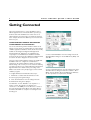
To configure Windows™ Terminal, follow these steps:
1 In Windows 3.1, double-click the Terminal icon in the
Accessories group in Program manager.
2 Select “Communications” from the Settings menu. The
Communications dialog box is displayed.
Set “Baud Rate” to 9600, “Data Bits” to 8, “Stop Bits” to 1,
“Parity” to None, “Flow Control” to Hardware and
“Connector” to the COM port on the PC used to connect to
the router. Uncheck the “Parity Check” and “Carrier Detect”
checkboxes. Click “OK” to accept the new settings and close
the dialog box.
3 Select “Terminal Emulation” from the Settings menu. In the
Terminal Emulation dialog box check “DEC VT-100 (ANSI)” and
click “OK”.
4 Select “Terminal Preferences” from the Settings menu. In the
Terminal Preferences dialog box uncheck “Local Echo”, “CR ->
CR/LF”, and “Use Function, Arrow, and Ctrl Keys for Windows”.
Set other parameters as required, then click “OK”.
A R 3 0 0 R O U T E R Q U I C K S TA R T G U I D E
7
5 To save the configuration, select “Save As” from the File
menu, then type a file name and press [Enter]. To reuse the
configuration in a future session, select “Open” from the File
menu, select the file name from the list and click “OK”.
6 You can customise Windows™ Terminal further by assigning
commonly used router commands to function keys. Select
“Function Keys” from the Settings menu, or select “Contents”
from the Help menu and click on the topic “Assign Tasks to
Function Keys”. To save the function key assignments, follow
step 5 above.
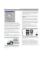
To configure Windows 95 HyperTerminal, follow these steps:
1 In Windows 95, from the Start Menu, select Programs >
Accessories > HyperTerminal to display the HyperTerminal
group. Double-click the Hypertrm.exe icon.
2 In the Connection Description dialog box, enter a name for
the connection (e.g. AR300) and select an icon from the
scrolling list. Click “OK”.
3 In the Phone Number dialog box, from the “Connect using:”
dropdown list select the “Direct to Com n” to match the COM
port on the PC used to connect to the router. Click “OK”.
5 Select “Properties” from the File menu. In the Connection
Properties dialog box, click the Settings tab and set “Function,
arrow, and ctrl keys act as” to “Terminal keys” and “Emulation”
to VT100.
4 In the COMn Properties dialog box set “Bits per second” to
9600, “Data bits” to 8, “Parity” to None, “Stop bits” to 1 and
“Flow control” to Hardware. Click “OK”.
6 Click “ASCII Setup” to display the ASCII Setup dialog box.
Uncheck the “Echo typed characters locally” and “Append line
feeds to incoming line ends” checkboxes. Set other parameters
as required, then click “OK” twice to dismiss all dialog boxes.
8
A R 3 0 0 R O U T E R Q U I C K S TA RT G U I D E
3 Check the operation by observing the state of the LEDs on
the front panel of the router. The Txd and Rxd LEDs will be lit as
data packets are transmitted and received via the interface. The
Link LED should be lit when a hub or personal computer is
connected to the Ethernet port.
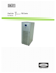
CONNECTING TELEPHONES AND FACSIMILE
MACHINES
To connect a telephone, facsimile machine, answering machine
or modem to an AT-AR300(S), AT-AR300(U), AT-AR310(S) or
AT-AR310(U) router with voice ports, follow these steps:
7 Select “Save” from the File menu to save the current
session. This creates an connection icon with the name you
assigned in the HyperTerminal group. To use the configuration,
double-click the connection icon in the HyperTerminal group.
When the HyperTerminal window appears, press [Enter] a
couple of times. The router’s login prompt will appear.
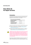
1 Connect the cable from the telephone, facsimile machine,
answering machine or modem to one of the voice ports on the
rear panel of the router. If necessary, use one of the stub cables
supplied with the router to convert from the router’s RJ11
connector to the national variant.
Note: Connect only approved apparatus to the voice ports. If
you experience difficulties with the attached apparatus please
contact your distributor or reseller in the first instance and not the
network provider.
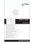
CONNECTING TO AN ETHERNET HUB OR PC
To connect any AR300 Series router to an Ethernet hub or
personal computer, follow these steps:
VOICE 3
VOICE 2
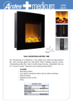
1 Connect the Ethernet port on the rear panel of the
router to either an Ethernet hub or the Ethernet port on a
LAN card in a personal computer, using the supplied CAT 5
Ethernet cable.
2 Set the MDX switch on the rear panel of the router to
“HUB” if the router is connected to an Ethernet hub, or “PC” if
the router is connected to a personal computer.
MDX
VOICE 1
VOICE 0
HUB
PC
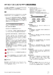
Connect the cable from the telephone, facsimile, answering machine or modem to
one of the voice ports on the rear panel of the AR300 Series router. Use one of the
PORT 1 (RS232)
ETHERNET 0
PORT 0 (RS232)
MDX
HUB
PC
Connect the supplied CAT 5 Ethernet cable to the Ethernet 0 port on the rear
panel of the AR300 Series router and set the MDX switch to “HUB” or “PC”
as appropriate.
supplied stub cables if necessary.
2 Check the operation by lifting the handset on the
telephone. A dial tone appropriate for the default territory
should be heard. If two or more telephones or telephones and
facsimile machines are connected, try making an internal call
from one telephone to another telephone or facsimile machine
by dialling “4” followed by the number of the voice port to
which the other telephone or facsimile machine is connected.
A R 3 0 0 R O U T E R Q U I C K S TA R T G U I D E
ORDERING ISDN IN THE USA AND CANADA
In the United States and Canada, Basic Rate ISDN is provided
using National ISDN-1, 5ESS or DMS-100 formats, all of which
are supported by the AR300 router. If National ISDN-1 is
available, you can select from a list of “Capability Packages”,
each providing different features. Contact your ISDN service
provider for more information. The AR300 router will accept
either one or two Service Profile Identifiers (SPIDs).
Note: Some ISDN service providers have lower tariffs for data-only
applications. If you do not require voice capabilities, order an ISDN
line that supports data only.
CONNECTING TO A BASIC RATE ISDN SERVICE
Warning:The factory default hardware settings described
here are correct for European Union (EU) countries. For
other countries, contact your distributor or reseller for
details of local requirements.
To connect an AT-AR300L(S), AT-AR370(S), AT-AR370(U),
AT-AR300(S), AT-AR300(U), AT-AR310(S) or AT-AR310(U)
router with a Basic Rate ISDN interface to a Basic Rate ISDN
service, follow these steps:
1 Check that the BRI hardware interface has the correct
termination for the local conditions. The AR300 router can only
operate in TE mode and is shipped with the standard 100Ω
termination jumpers removed. This is appropriate for most
situations, where the local building wiring provides the ISDN
termination. Your distributor or reseller can advise you whether
or not termination jumpers are required.
2 Connect the supplied CAT 5 ISDN cable from the BRI
interface on the rear panel of the router to the ISDN service
provider’s termination point. In the USA and Canada this is an
ISDN line wall jack. In other countries it is an NT1.
PORT 1 (RS232)
9
Note: If you wish to make your own ISDN cable, see the AR Router
Hardware Reference for a detailed description of how to wire an
ISDN interface cable.
3 Check the operation by observing the state of the LEDs on
the front panel of the router.
In some territories (e.g. New Zealand and the European Union)
the Active LED will be lit if the link to the NT1 is operational. In
other territories (e.g. Australia) the Active LED will only be lit
when the router attempts a call. In this case, a simple way to
make a call is to connect a telephone to one of the voice ports,
lift the telephone handset and dial the external call prefix
number (9). A dial tone appropriate for the default territory
should be heard, and the Active LED should be lit.
The B1 and B2 LEDs will be lit as data packets are sent and
received on the B1 and B2 channels, respectively. To test this
you will need to configure a routing protocol such as IP or IPX
to use ISDN, using the router’s command line interface. See
Configuring ISDN, Configuring an IP Network and Configuring a
Novell IPX Network later in this guide for more information.
CONNECTING TO A PRIMARY RATE ISDN
SERVICE
Warning:The factory default hardware settings described
here are correct for European Union (EU) countries. For
other countries, contact your distributor or reseller for
details of local requirements.
To connect an AT-AR390 or AT-AR395 router to a Primary
Rate ISDN service, follow these steps:
1 Check that the PRI hardware interface has the correct
termination for the local conditions. The AT-AR390 and
AT-AR395 are shipped with PRI hardware pre-configured for
normal TE mode operation and with the standard termination
jumpers removed. This is appropriate for most situations. If the
PRI hardware is to be operated in a non-standard mode, contact
your distributor or reseller for assistance. The commands:
SHOW PRI STATE
0
PORT 0 (RS232)
BRI 0
CONFIG
1
2
3
4
Connect the supplied CAT 5 ISDN cable from the BRI 0 port on the rear panel of the
AR300 router to the ISDN service provider’s termination point.
SHOW PRI CONFIGURATION
display the state of the PRI interface and the modules that have
configured to use the PRI interface. In particular, check the
output of the SHOW PRI STATE command that “ISDN
Interface type” is set to “TE”. If not, contact your distributor
or reseller for assistance, or see the AR Series Router Software
Reference for more information.
10
A R 3 0 0 R O U T E R Q U I C K S TA RT G U I D E
2 Connect an approved ISDN 120Ω cable or 75Ω cable pair
from the ISDN service provider’s termination point to the PRI
interface on the rear panel of the router.
Note: If you wish to make your own ISDN cables, see the AR
Router Hardware Reference for a detailed description of how to
wire an ISDN interface cable.
SYNCHRONOUS 0
THERNET 0
CONFIG
MDX
1
HUB
2
3
4
PC
Connect the NTU to the synchronous port on the rear panel of the AR300 router
PRI 0
using the appropriate transition cable.
2 Check the configuration of the port, by typing the command:
120Ω
75Ω Tx
120Ω
75Ω Rx
Connect the ISDN service provider’s termination point to the Primary Rate ISDN port
on the rear panel of the AT-AR390 or AT-AR395 router using an approved ISDN
120Ω cable or 75Ω cable pair.
3 Using the push button to the left of the PRI interface, set
the 120Ω LED to match the cable type used. If a 120Ω cable is
used, press the push button until the LED is lit. If a 75Ω cable
pair is used, press the push button until the LED is not lit.
4 Check the operation by observing the state of the LEDs on
the front panel of the router. The Active LED should be lit
indicating the link to the NT is operational. The TxD and RxD
LEDs will be lit as data packets are transmitted and received on
any B channel or the D channel. See Configuring ISDN,
Configuring an IP Network and Configuring a Novell IPX Network
later in this guide for more information about configuring ISDN
calls and routing protocols.
CONNECTING TO A LEASED LINE CIRCUIT
To connect an AT-AR350, AT-AR370(S) or AT-AR370(U) router
with a synchronous interface to a leased line circuit, follow these
steps:
SHOW SYN=0
Verify that the information displayed is correct. In particular,
“State” should be set to “enabled” and “Interface type” should
match the transition cable used.
3 Configure a data link layer module, such as PPP (Point-to-Point
Protocol), Frame Relay or X.25 LAPB, to use the synchronous
interface. To create a PPP interface 0 over synchronous port 0,
type the command:
CREATE PPP=0 OVER=SYN0
4 Check the configuration by typing the commands:
SHOW SYN=0
SHOW PPP=0
The output of the SHOW SYN command should show “Active”
set to “yes” and “Module” set to “ppp”. The output of the
SHOW PPP command should show interface ppp0 over syn0
with “LCP” as the control protocol.
5 Check the operation by observing the state of the LEDs on
the front panel of the router. The Txd and Rxd LEDs will be lit
when data is sent or received on the synchronous interface.
6 For more information about configuring Frame Relay or
X.25 services, see the AR Series Router Software Reference.
1 Using the appropriate approved transition cable (RS-232,
X.21 or V.35), connect the synchronous port on the rear of the
router to the NTU supplied by the telecommunications
network provider.
CONNECTING A TERMINAL OR MODEM
Note: If you wish to make your own cable, see the AR Router
Hardware Reference for a detailed description of how to wire a
transition cable.
1 Use the supplied console cable or an approved terminal
cable to connect a terminal to an asynchronous port on the
rear panel of the router, or use an approved modem cable to
connect a modem to an asynchronous port on the rear panel
To connect a terminal or modem to any AR300 Series router,
follow these steps:
A R 3 0 0 R O U T E R Q U I C K S TA R T G U I D E
of the router. Models AT-AR300(S), AT-AR300L(S) and
AT-AR310(S) have DB9 female connectors. Models
AT-AR300(U), AT-AR300L(U), AT-AR310(U), AT-AR350,
AT-AR370(S), AT-AR370(U), AT-AR390 and AT-AR395 have
DB9 male connectors.
Note: If you wish to make your own cable, see the AR Router
Hardware Reference for a detailed description of how to wire a
terminal or modem cable.
50
PORT 1 (RS232)
PORT 0 (RS232)
ETHERNET 0
MDX
HUB
PC
Connect the terminal or modem to one of the asynchronous ports (Port 0 or Port 1)
on the rear panel of the AR300 Series router using an approved cable. Some models
have only one asynchronous port (Port 0).
11
2 Check that the terminal or modem’s communication
settings match the settings of the asynchronous port. By default,
asynchronous ports on the AR300 router are set to 9600 baud,
8 data bits, 1 stop bit, no parity and hardware flow control.
Refer to the user manual supplied with the terminal or modem
for details of how to change the communications settings for
the terminal or modem.
If the terminal or modem is to be used with communications
settings other than the router’s default settings, the
asynchronous port must be configured to match the terminal
or modem settings using the SET PORT command. If a modem
is being connected, the CDCONTROL parameter must be set
to “CONNECT” and the FLOW parameter must be set to
“HARDWARE”. See the router’s online help or the AR Series
Router Software Reference for more information.
3 If a modem is being connected, the router must be
configured to make and/or accept calls via the modem using an
Asynchronous Call Control (ACC) call. An ACC call definition is
created using the ADD ACC CALL command. See the router’s
online help or the AR Series Router Software Reference for more
information.
12
A R 3 0 0 R O U T E R Q U I C K S TA RT G U I D E
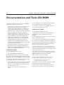
Documentation and Tools CD-ROM
The AR Series Router Documentation and Tools CD-ROM is
bundled with every AR router and includes:
For more information about using the Adobe Acrobat Reader,
select “Acrobat Reader Help” from the Help menu.
• The AR Series Router Documentation Set in Adobe Acrobat
PDF format—the complete reference to installing,
configuring and managing the AR series of multiprotocol
routers, including detailed descriptions of all commands.
4 To install any of the tools on the CD-ROM, click on the
“Tools” button in the CD Browser menu.
• Application Notes—a collection of technical and background
papers on the application of AR router technologies.
• Configuration Examples—a collection of ready-to-use
examples of typical network configurations, complete with
scripts to download to an AR router using AT-TFTP.
USING AT-TFTP SERVER
To use AT-TFTP Server, follow these steps:
1 If AT-TFTP Server has not yet been installed, install it now
from the AR Series Router Documentation and Tools
CD-ROM.
• AT-TFTP Server for Windows, for downloading software
releases, scripts and other files to or from an AR router.
2 Select AT-TFTP Server from the Start > Programs > Allied
Telesyn > AT-TFTP Server menu.
• Adobe Acrobat Reader for Windows for viewing and
printing the online documentation in PDF format. Get
instant access to information with full-text searching of PDF
documents by keyword or phrase.
3 To set preferences for the AT-TFTP Server, select “Options”
from the File menu to display the “Set Preferences” dialog box.
• Microsoft Internet Explorer and Netscape Communicator.
• Demonstration versions of networking utilities, such as
AR-Remote File Manager (AR-RFM) from Allied Telesyn and
F-Secure’s Secure Shell client for Windows.
USING THE CD-ROM
To use the CD-ROM, follow these steps:
1 Insert the CD-ROM in the CD-ROM drive.
2 If the CD Browser menu does not appear automatically
after a few seconds, select “Run” from the Start Menu and type
d:\start.exe (where d: is the CD-ROM drive letter). Click OK.
3 To view a document, click on the document title. To navigate
around PDF documents, do one of the following:
• Use the toolbar buttons, keyboard shortcuts, and commands
from the Document menu to page through the document.
• Click on a bookmark, thumbnail or hypertext link to jump
to a specific section or topic.
• Use the Search command to search for keywords or
phrases.
The “Default file transfer directory” field specifies the directory
AT-TFTP Server will read from or write to, for file requests
that do not include a directory specification.
To prevent unauthorised access to private directories, enter a
path name in the “Restrict to directory” field. AT-TFTP Server
will use only the specified directory, even if file requests contain
references to other directories.
Select “Read only” to prevent files being written to the PC. To
use the PC to archive router scripts created using the router’s
CREATE CONFIG command, select “Read Write”.
Make any required changes and click “OK”.
4 To load a file from AT-TFTP Server to the router, on a
terminal connected to the router type the command:
LOAD METHOD=TFTP FILE=filename
SERVER=ipadd DEST=FLASH
where filename is the name of the file to download and ipadd is
the IP address of the PC running AT-TFTP Server.
5 TFTP requests are logged to the AT-TFTP Server main
window. To save the log, select “Save As” from the File menu.
A R 3 0 0 R O U T E R Q U I C K S TA R T G U I D E
13
Configuring ISDN
This section describes how to configure ISDN on the AR300
router using the command line interface.
ISDN on the router requires minimal user configuration, other
than selecting a territory, creating call definitions and configuring
the Point-to-Point Protocol (PPP) to use the ISDN calls. The
lower layers of the ISDN protocol stack (BRI, LAPD and Q.931)
are automatically configured when the router starts up.
Warning:The factory default hardware and software
settings described here are correct for European Union
(EU) countries. For other countries, contact your distributor
or reseller for details of local requirements.
CONFIGURING BASIC RATE ISDN
To configure Basic Rate ISDN on the AR300 router, follow
these steps:
1 Check the BRI hardware configuration. The AR300 router
can only operate in TE mode and is shipped with the standard
100Ω termination jumpers removed. This is appropriate for
most situations, where the building wiring provides the ISDN
termination. Your distributor or reseller can advise you whether
or not termination jumpers should be installed.
2 Select the country in which the router is being operated,
using the command:
SET SYSTEM TERRITORY={AUSTRALIA|CHINA|
EUROPE|JAPAN|KOREA|NEWZEALAND|USA}
The territory determines which Q.931 profile is used on the
ISDN interface and country-specific settings for the PBX
telephony services. For example, to select the Q.931 profile
and country-specific settings for the United States, use the
command:
SET SYSTEM TERRITORY=USA
Warning: If you are not sure which territory to use, contact
your distributor or reseller. Failure to select the correct
territory will invalidate the approval of this product with
respect to the applicable national standards for the
country in which the product is used.
For installations in the USA, go to step 4. For installations in
other countries, go to step 3.
3 In countries other than the USA, the router’s ISDN directory
numbers and subaddresses may be set with the command:
SET Q931=0 NUM1=number NUM2=number
SUB1=subaddress SUB2=subaddress
This step is only required if the router is sharing the ISDN S/T
bus with other ISDN devices. See the AR Series Router Software
Reference for more information.
Go to Step 5.
4 In the USA, the ISDN switch type and SPIDs values may also
need to be set. Setting the system territory to USA
automatically sets the ISDN switch type to National ISDN-1.
This should be correct for all new ISDN installations. If the
router is to be connected to another switch type, the switch
type can be set with the command:
SET Q931=0 PROFILE=DMS-100
for a Northern Telecom DMS-100 switch running custom
software, or:
SET Q931=0 PROFILE=5ESS
for a Lucent 5ESS switch running custom software.
If the switch type is not National ISDN-1, the SPIDs (supplied
by the ISDN service provider) must also be entered with the
command:
SET Q931=0 SPID1=spid SPID2=spid
If the switch type is National ISDN-1 the router will, when first
turned on, attempt to obtain the SPIDs itself from the switch
using the Auto SPID procedures. The success of this procedure
can be monitored with the command:
SHOW Q931=0 SPID
If the Auto SPID procedure succeeds the router will either
select the SPID values to use by itself, or tell the user (in the
output of the SHOW Q931 SPID command) how to select the
SPID values.
If the Auto SPID procedures fail, SPIDs can be entered manually
with the command:
SET Q931=0 SPID1=spid SPID2=spid
14
A R 3 0 0 R O U T E R Q U I C K S TA RT G U I D E
Directory numbers and subaddresses can be entered with
the command:
SET Q931=0 NUM1=number NUM2=number
SUB1=subaddress SUB2=subaddress
The directory numbers and subaddresses must be supplied by
the ISDN service provider. If the directory number is a full 10
digit number (3 digit area code plus 7 digit number), the router
will append the digits “0101” to the number and attempt SPID
initialisation with the result. This is known as the Generic SPID
procedure. If SPID initialisation has already taken place and
SPIDs have been obtained through the Auto SPID procedure,
then either these SPIDs are the same as the Generic SPID and
the router will successfully reinitialise, or the SPIDs are not the
same as the Generic SPID and the router will not initialise. In
this case, the router will revert to using the Auto SPID values.
5 Create ISDN call definitions to enable the router to make
ISDN calls to other devices on the ISDN network. This is the
only step that must be completed to configure ISDN on the
router. Before a call can be made from one router to another,
call definitions must be created on both routers, using
the command:
ADD ISDN CALL=name NUMBER=number
PRECEDENCE={IN|OUT} options...
For example, a Remote Office router is to be connected to the
Head Office router via ISDN. The ISDN number of the Remote
Office router is 1234567. The ISDN number of the Head Office
router is 9876543. The called party subaddress information
element (IE) is used to carry connection information, and PPP
interfaces will be created explicitly to use the ISDN calls. Either
router can initiate the call, but calls from the Remote Office
have precedence. On the Head Office router, create a call to
the Remote Office router:
ADD ISDN CALL=ROHO OUTSUB=LOCAL
SEARCHSUB=LOCAL NUMBER=1234567 PREC=IN
On the Remote Office router, create a call to the Head
Office router:
ADD ISDN CALL=ROHO OUTSUB=LOCAL
SEARCHSUB=LOCAL NUMBER=9876543
PREC=OUT
Each call has the same name (ROHO), and this name is passed
via the called subaddress IE to provide identification to the
remote end of the link. Each router will search for this call
using the called subaddress IE.
The precedence must be set to ensure that in the event of a
call collision—the same call being made and answered at the
same time—one call is completed and other call is cleared. The
direction of precedence is not important, but it must be set to
IN at one end of the call and OUT at the other end of the call.
The ISDN number is the exact sequence required to reach the
remote router from the local router, including STD access
codes and area codes. The number may contain only decimal
digits. Hyphens and other characters will result in an error.
Check that the ISDN calls have been successfully added with
the command:
SHOW ISDN CALL
6 Create PPP interfaces to use the ISDN calls. PPP provides
the link layer protocol and enables multiple network and
transport layer protocols such as IP and Novell® IPX to be
carried over the same ISDN link.
For example, on the Head Office router create PPP interface 0
to use the ISDN call ROHO:
CREATE PPP=0 OVER=ISDN-ROHO
On the Remote Office router, create PPP interface 0 to use the
ISDN call ROHO:
CREATE PPP=0 OVER=ISDN-ROHO
Check the configuration with the commands:
SHOW ISDN CALL
SHOW PPP
The call ROHO should appear in the output of the SHOW
ISDN CALL command. The output of the SHOW PPP
command should show interface ppp0 over ISDN-ROHO.
ISDN is now ready to be used by routing protocols such as IP
and IPX.
CONFIGURING PRIMARY RATE ISDN
To configure Primary Rate ISDN on the AT-AR390 or
AT-AR395 router, follow these steps:
1 The AT-AR390 and AT-AR395 can operate in either TE or NT
mode, using 75Ω or 120Ω termination. The router is shipped
with jumpers set to TE mode, 75Ω termination, Tx grounded and
Rx grounded via a 100nF capacitor. This is appropriate for most
situations. Your distributor or reseller can advise you whether or
not grounding jumpers should be installed.
Warning: Disconnect the router from the mains power
supply before removing the router lid.
A R 3 0 0 R O U T E R Q U I C K S TA R T G U I D E
2 Select the country in which the router is being operated,
using the command:
SET SYSTEM TERRITORY={AUSTRALIA|CHINA|
EUROPE|JAPAN|KOREA|NEWZEALAND|USA}
The territory determines which Q.931 profile is used on the
ISDN interface and country-specific settings for the PBX
telephony services. For example, to select the Q.931 profile and
country-specific settings for New Zealand, use the command:
SET SYSTEM TERRITORY=NEW ZEALAND
Warning: If you are not sure which territory to use, contact
your distributor or reseller. Failure to select the correct
territory will invalidate the approval of this product with
respect to the applicable national standards for the
country in which the product is used.
3 The router’s ISDN directory numbers and subaddresses may
be set with the command:
SET Q931=0 NUM1=number NUM2=number
SUB1=subaddress SUB2=subaddress
This step is only required if the router is sharing the ISDN S/T
bus with other ISDN devices. See the AR Series Router Software
Reference for more information.
4 Create ISDN call definitions to enable the router to make
ISDN calls to other devices on the ISDN network. This is the
only step that must be completed to configure ISDN on the
router. Before a call can be made from one router to another,
call definitions must be created on both routers, using
the command:
ADD ISDN CALL=name NUMBER=number
PRECEDENCE={IN|OUT} options...
For example, a Remote Office router is to be connected to the
Head Office router via ISDN. The ISDN number of the Remote
Office router is 1234567. The ISDN number of the Head Office
router is 9876543. The called party subaddress information
element (IE) is used to carry connection information, and PPP
interfaces will be created explicitly to use the ISDN calls. Either
router can initiate the call, but calls from the Remote Office
have precedence. On the Head Office router, create a call to
the Remote Office router:
ADD ISDN CALL=ROHO OUTSUB=LOCAL
SEARCHSUB=LOCAL NUMBER=1234567 PREC=IN
15
On the Remote Office router, create a call to the Head
Office router:
ADD ISDN CALL=ROHO OUTSUB=LOCAL
SEARCHSUB=LOCAL NUMBER=9876543
PREC=OUT
Each call has the same name (ROHO), and this name is passed
via the called subaddress IE to provide identification to the
remote end of the link. Each router will search for this call
using the called subaddress IE.
The precedence must be set to ensure that in the event of a
call collision (the same call being made and answered at the
same time), one call is completed and other call is cleared. The
direction of precedence is not important, but it must be set to
IN at one end of the call and OUT at the other end of the call.
The ISDN number is the exact sequence required to reach the
remote router from the local router, including STD access
codes and area codes. The number may contain only decimal
digits. Hyphens and other characters will result in an error.
Check that the ISDN calls have been successfully added with
the command:
SHOW ISDN CALL
5 Create PPP interfaces to use the ISDN calls. PPP provides
the link layer protocol and enables multiple network and
transport layer protocols such as IP and Novell® IPX to be
carried over the same ISDN link.
For example, on the Head Office router create PPP interface 0
to use the ISDN call ROHO:
CREATE PPP=0 OVER=ISDN-ROHO
On the Remote Office router, create PPP interface 0 to use the
ISDN call ROHO:
CREATE PPP=0 OVER=ISDN-ROHO
Check the configuration with the commands:
SHOW ISDN CALL
SHOW PPP
The call ROHO should appear in the output of the SHOW
ISDN CALL command. The output of the SHOW PPP
command should show interface ppp0 over ISDN-ROHO.
ISDN is now ready to be used by routing protocols such as IP
and IPX.
16
A R 3 0 0 R O U T E R Q U I C K S TA RT G U I D E
CONFIGURING ISDN DIAL ON DEMAND
CONFIGURING ISDN BANDWIDTH ON
A PPP interface that uses an ISDN call as its physical interface
can be configured for dial on demand operation. The ISDN call
is activated only when there is data to be transmitted, and is
disconnected when the link has been idle for a period of time.
DEMAND
To configure ISDN dial on demand operation, follow these steps:
1 Complete steps 1 to 5 of Configuring Basic Rate ISDN, or
steps 1 to 4 of Configuring Primary Rate ISDN above.
2 Create PPP interfaces to use the ISDN calls and enable the
IDLE timer. Using the example in step 6 of Configuring Basic Rate
ISDN above, on the Head Office router create PPP interface 0
to use the ISDN call ROHO:
CREATE PPP=0 OVER=ISDN-ROHO IDLE=ON
On the Remote Office router, create PPP interface 0 to use the
ISDN call ROHO:
CREATE PPP=0 OVER=ISDN-ROHO IDLE=ON
Setting the IDLE parameter to ON enables the idle timer and
sets the timeout period to 60 seconds. ISDN calls will be
disconnected if there has been no data transmitted over the link
for 60 seconds. To enable the idle timer with a different timeout
period, specify a time in seconds instead of the value ON.
PPP interface 0 is now configured for dial on demand operation
and any routing protocols such as IP and IPX that are
configured to use PPP interface 0 will automatically inherit the
dial on demand functionality.
A PPP interface can be configured to use up to two B channels
on an ISDN Basic Rate interface, to provide bandwidth on
demand. PPP activates additional ISDN channels when the
bandwidth exceeds an upper threshold, and deactivates ISDN
channels as bandwidth falls below a lower threshold.
To configure an ISDN connection for bandwidth on demand
operation, follow these steps:
1 Complete steps 1 to 5 of Configuring Basic Rate ISDN, or
steps 1 to 4 of Configuring Primary Rate ISDN above.
2 Create a second ISDN call on each router, identical to the
call ROHO but with the name DEMAND.
3 Create PPP interfaces to use the ISDN calls, enable the
IDLE timer and add a second demand channel. Using the
example in step 6 of Configuring Basic Rate ISDN or step 5 of
Configuring Primary Rate ISDN above, on the Head Office router
create PPP interface 0:
CREATE PPP=0 OVER=ISDN-ROHO IDLE=ON
ADD PPP=0 OVER=ISDN-DEMAND TYPE=DEMAND
On the Remote Office router, create PPP interface 0:
CREATE PPP=0 OVER=ISDN-ROHO IDLE=ON
ADD PPP=0 OVER=ISDN-DEMAND TYPE=DEMAND
PPP interface 0 is now configured for bandwidth on demand
operation and any routing protocols such as IP and IPX that are
configured to use PPP interface 0 will automatically inherit the
bandwidth on demand functionality.
A R 3 0 0 R O U T E R Q U I C K S TA R T G U I D E
17
Configuring an IP Network
TCP/IP is the most widely used network protocol. The Internet
uses TCP/IP for routing all its traffic. TCP/IP provides a range of
services including remote login, Telnet, file transfer (FTP), Email
and access to the World-Wide Web.
Protocol (PPP) over a wide area link. Each router is attached to
an Ethernet LAN on which there is a mixture of PCs and hosts.
The AR300 router routes TCP/IP across the wide area network
using services like ISDN, Frame Relay and leased lines, enabling
remote TCP/IP LANs to be joined together as a single internet
to exchange information.
1 Ensure that the routers to be configured are connected to
the Ethernet LAN and the wide area link, and that the link is
operational. See Getting Connected for information about
connecting the router to a physical network.
This example illustrates the steps required to configure TCP/IP
using the router’s command line interface. Two routers running
TCP/IP will be connected together using the Point-to-Point
2 Connect a terminal to the console port (port 0) on each
router, as described in the AR300 Series Router Quick Install
BEFORE YOU START
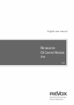
Head Office Router
Remote Office Router
172.16.254.1
172.16.254.2
PPP Data Link
172.16.8.33
192.168.31.30
172.16.8.0
TCP/IP Host
Head Office Router
eth0
192.168.31.16
Local PC
Remote PC
Configuration Parameter
Ethernet interface
172.16.8.33
Ethernet interface IP address
172.16.8.0
Ethernet LAN IP subnet address
255.255.255.0
ppp0
Ethernet LAN IP subnet mask
PPP interface
172.16.254.1
PPP interface IP address
172.16.254.0
PPP interface IP subnet address
255.255.255.0
PPP interface IP subnet mask
Remote PC
Remote Office Router
eth0
192.168.31.30
192.168.31.16
255.255.255.240
ppp0
172.16.254.2
172.16.254.0
255.255.255.0
18
A R 3 0 0 R O U T E R Q U I C K S TA RT G U I D E
Guide. Alternatively, you can connect a PC to the console port
and use a terminal emulation program like Windows™
Terminal.
3 Login to the MANAGER account on each router, as
described in Installing the AR300 Router.
4 Collect together the information that you will need to
configure IP. We recommend you photocopy the table on page
17 and fill in the details.
CONFIGURING IP
The following steps are required:
1. Configure the PPP Link.
2. Configure the IP routing module on both routers.
3. Test the configuration.
4 A routing protocol can be enabled so that the routers can
exchange information about routes to all of the IP devices
(hosts, PCs, file servers, etc.) on the internet. For this example
RIP (Routing Information Protocol) will be used. On the Head
Office router enter the commands:
ADD IP RIP INT=ETH0
ADD IP RIP INT=PPP0
SHOW IP RIP
The SHOW IP RIP command confirms that RIP is active on the
Ethernet and WAN (PPP) interfaces.
5 Repeat this procedure for the Remote Office router,
entering the commands:
ADD IP RIP INT=ETH0
ADD IP RIP INT=PPP0
SHOW IP RIP
Configure the PPP Link
Configure PPP interface 0 on each router to use the wide area
link. See Getting Connected for information about configuring
PPP to use a synchronous link. See Configuring ISDN for
information about configuring PPP to use an ISDN call. If the
PPP interface is configured for dial on demand operation (see
Configuring ISDN Dial on Demand) or bandwidth on demand
operation (see Configuring ISDN Bandwidth on Demand), these
services will automatically be used by the IP routing software.
Configure IP Routing
1 Clear any pre-existing IP configuration and turn on the IP
routing software on each router, using the commands:
PURGE IP
ENABLE IP
2 On the Head Office router define two IP interfaces, one for
the Ethernet LAN and one for the wide area link:
ADD IP INT=ETH0 IP=172.16.8.33
MASK=255.255.255.0
ADD IP INT=PPP0 IP=172.16.254.1
MASK=255.255.255.0
3 Repeat this procedure on the Remote Office router,
defining one IP interface for the Ethernet LAN and one for the
wide area link:
ADD IP INT=ETH0 IP=192.168.31.30
MASK=255.255.255.240
ADD IP INT=PPP0 IP=172.16.254.2
MASK=255.255.255.0
6 The IP routing software is now configured and operational
on both routers.
Test the Configuration
The IP configuration can now be checked using the following
commands and then functionally tested by establishing a Telnet
(remote access) connection to the remote router.
1 To check the routes, type (on either router):
SHOW IP ROUTE
This should produce a display (on the Head Office router) like
that shown on page 19. For each router, there should be a
route to the LAN and PPP interfaces on the local router and a
route to the LAN interface on the remote router.
2 Test the PPP link between the two routers using the PING
command on each router to send ping packets to the router at
the remote end of the PPP link. On the Head Office router use
the command:
PING 192.168.31.30
On the Remote Office router use the command:
PING 172.16.8.33
Within a few seconds the router will display a message like:
Echo reply 1 from 172.16.8.33 time delay
20 ms
indicating a response was received from the router at the
remote end of the PPP link.
Note: We have used the Ethernet address in this example but you
can ping any of the remote router’s assigned IP addresses.
A R 3 0 0 R O U T E R Q U I C K S TA R T G U I D E
19
Example output from the SHOW IP
ROUTE command for a basic TCP/IP
network.
Example output from the SHOW PPP
command for a basic TCP/IP network.
IP Routes
------------------------------------------------------------------------------Destination
Mask
Nexthop
Interface
Age
DLCI/Circ.
Type
Policy
Protocol
Metric
Preference
------------------------------------------------------------------------------172.16.8.0
255.255.255.0
0.0.0.0
eth0
1382
direct
0
interface
1
0
172.16.31.0
255.255.255.0
172.16.254.2
ppp0
71
remote
0
rip
16
100
172.16.254.0
255.255.255.0
0.0.0.0
ppp0
1382
direct
0
interface
1
0
-------------------------------------------------------------------------------
Name
Enabled ifIndex Over
CP
State
----------------------------------------------------------------------------ppp0
YES
04
IPCP
OPENED
isdn-roho
LCP
OPENED
-----------------------------------------------------------------------------
3 To functionally test the connection between the two routers,
use Telnet to establish a connection to the remote router. Enter
the following command on the Head Office router to connect
to the Remote Office router:
TELNET 192.168.31.30
You will see the login screen for the Remote Office router. To
connect from the Remote Office router to the Head Office
router, on the Remote Office router use the command:
TELNET 172.16.8.33
Note: We have used the Ethernet address in this example but you can
Telnet to any of the remote router’s assigned IP addresses.
Save the Configuration
Save the new dynamic configuration as a script, by entering
the command:
CREATE CONFIG=IPCONF.SCP
TROUBLESHOOTING IP CONFIGURATIONS
No Route Exists to the Remote Router
1 Wait for at least one minute to ensure that a RIP update has
been received.
2 Repeat steps 4 and 5 above. Check that the PPP link is
OPENED for both LCP and IP by entering the command:
SHOW PPP
The display should look like that shown above.
3 Try restarting the IP routing software (a warm restart), by
entering the command:
RESET IP
If the route still does not appear, contact your distributor or
reseller for assistance.
Telnet Fails
1 If Telnet to a router fails, check that the IP address you used
matches the one assigned to the router. Check that RIP is
configured correctly (steps 4 and 5 above). Check that the IP
Telnet server is enabled on each router, using the command:
SHOW IP
If the Telnet server is disabled, enable the Telnet server with
the command:
ENABLE IP TELNETSERVER
2 If Telnet into a host on the remote LAN fails, but works into
the remote router, check the IP address you are using is correct.
Check that both routers are gateways, not servers by typing:
SHOW IP
The “IP Packet Forwarding” field in the output should be set to
“Enabled”. The host’s TCP/IP software should be configured to
use the Head Office router as its gateway. Refer to the
documentation for the host TCP/IP software for more
information about configuring a gateway.
3 Contact your distributor or reseller for assistance.
20
A R 3 0 0 R O U T E R Q U I C K S TA RT G U I D E
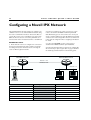
Configuring a Novell IPX Network
This example illustrates the steps required to configure a pair
of AR300 routers to create a Novell® IPX internetwork, using
the router’s command line interface. In this scenario, PCs at a
remote office need access to a Novell file server at the Head
Office site. The two sites are connected by a PPP link over a
wide area link—either a dedicated leased line or an ISDN call.
2 Connect a terminal to the console port (port 0) on each
router, as described in the AR300 Series Router Quick Install
Guide. Alternatively, you can connect a PC to the console port
and use a terminal emulation program like Windows™ Terminal,
or Telnet to the routers using a Telnet client. To use Telnet both
routers must be configured for IP. See Configuring an IP Network
for details.
BEFORE YOU START
3 Login to the MANAGER account on each router, as
described in the AR300 Series Router Quick Install Guide.
1 Ensure that the routers to be configured are connected to
the wide area link, and that the wide area link is operational.
See Getting Connected for information about connecting the
router to different physical networks.
4 Collect the information that you will need to configure IPX.
We recommend you photocopy the table on page 20 and fill in
the details. Pay particular attention to the following points:
Head Office Router
Remote Office Router
Network = 129
PPP Data Link
Network = 401
Network = 12
Remote PC
Netware
File Server
Head Office Router
eth0
802.3
401
1
ppp0
129
2
Configuration Parameter
Ethernet interface
Ethernet encapsulation
Novell network number for Ethernet
IPX circuit over Ethernet
PPP interface
Novell network number for PPP
IPX circuit over PPP
Remote PC
Remote Office Router
eth0
802.3
12
1
ppp0
129
2
A R 3 0 0 R O U T E R Q U I C K S TA R T G U I D E
• Each network in a Novell internet, including all LANs and
WAN links, must be assigned a network number. Novell file
servers also have an internal network number. These
network numbers must be unique across the Novell
internet—no two networks or file servers may use the
same network number. All devices attached to a network
must use the same network number to refer to the
network. Check to see what numbers your file servers are
using. Many schemes exist to ensure that numbers are kept
unique, for example, using the hexadecimal representation
of the IP address or the telephone number of each location.
• All routers, file servers and workstations attached to an
Ethernet LAN must use the same Ethernet encapsulation or
frame type. The following table lists the Novell frame type
and the equivalent AR router encapsulation:
Novell Frame Type
Router Encapsulation
Ethernet_802.3
802.3
Ethernet_802.2
802.2
Ethernet_II
EthII
Ethernet_SNAP
SNAP
21
PPP interface is configured for dial on demand operation (see
Configuring ISDN Dial on Demand) or bandwidth on demand
operation (see Configuring ISDN Bandwidth on Demand), these
services will automatically be used by the IPX routing software.
Configure IPX Routing
1 Purge the IPX static database to clear any preexisting IPX
configuration and enable the IPX routing software on each
router, using the commands:
PURGE IPX
ENABLE IPX
2 On the Head Office router define two IPX circuits, one for
the Ethernet interface and one for the wide area link, using:
ADD IPX CIRC=1 INT=ETH0 NETW=401
ENCAP=802.3
ADD IPX CIRC=2 INT=PPP0 NETW=129
3 Repeat this procedure on the Remote Office router,
defining one IPX circuit for the Ethernet interface and one for
the wide area link, using:
ADD IPX CIRC=1 INT=ETH0 NETW=12
ENCAP=802.3
ADD IPX CIRC=2 INT=PPP0 NETW=129
You can determine the file server name, internal network
number, Ethernet frame type and Ethernet network number
used by a Novell file server, by interrogating the file server
itself. From the management console attached to the Novell file
server, at the system console prompt type the command
“config” and record the values of the fields “File server name”,
“IPX internal network number”, “Frame type” and “LAN
protocol”. You can also access the system console by running
the rconsole utility from any workstation logged in as
supervisor. For more details, contact your local Novell network
administrator or refer to the Novell documentation.
CONFIGURING IPX
The following steps are required:
1. Configure the PPP link.
2. Configure the routers for IPX.
3. Test the configuration.
Configure the PPP Link
Configure PPP interface 0 on each router to use the wide area
link. See Getting Connected for information about configuring
PPP to use a synchronous link. See Configuring ISDN for
information about configuring PPP to use an ISDN call. If the
4 The routers are now configured for IPX and can exchange
routes and service information.
Test the Configuration
1 Examine the route table and service table on each router,
using the commands:
SHOW IPX ROUTE
SHOW IPX SERVICE
The route table will contain paths from each Novell device
which advertises routes, for example file servers and routers.
The service table lists all the services, such as file services and
print services, that devices are advertising.
Note: The actual contents of the table varies with the number and
type of file servers present on the network, but there should be a
route from each router to the other, and all services shown as local
(i.e. via eth0) on one router, should also be visible on the other router,
via the PPP link.
2 Test that a workstation on the Remote Office LAN can
login to the file server on the Head Office LAN.
22
A R 3 0 0 R O U T E R Q U I C K S TA RT G U I D E
Example output from the SHOW IPX
ROUTES command for a basic Novell
IPX network.
IPX routes
Network
Nexthop
Circuit
Hops
Cost
Uptime Type
-----------------------------------------------------------------------------00000401 Local
1 (eth0)
1
1
85973 Local
00000129 Local
2 (ppp0)
1
1
85973 Local
00000012 00000129:0000cd000d26
2 (ppp0)
2
1
85973 RIP
------------------------------------------------------------------------------
Example output from the SHOW IPX
SERVICES command for a basic
Novell IPX network.
IPX services
Name
Age
Address
Server type
Circuit
Hops Defined
-------------------------------------------------------------------------------ACCOUNTS
0
00007500:000000000001:0451
0004:FileServer
1 (eth0)
1
SAP
ACCOUNTS
0
00007500:000000000001:8104
0107:RConsole
1 (eth0)
1
SAP
TYPISTS
0
00000012:0080488018d8:0451
0004:FileServer
2 (ppp0)
3
SAP
--------------------------------------------------------------------------------
Example output from the SHOW PPP
command for a basic Novell IPX
network.
Name
Enabled ifIndex Over
CP
State
----------------------------------------------------------------------------ppp0
YES
04
IPXCP
OPENED
isdn-roho
LCP
OPENED
-----------------------------------------------------------------------------
Save the Configuration
Save the new dynamic configuration as a script, by entering
the command:
CREATE CONFIG=IPXCONF.SCP
Check that there are two circuits, and for each circuit check
that the circuit is enabled, uses the correct interface and
encapsulation (for Ethernet interfaces), the network number is
correct and “On demand” is set to “no”. If not, then repeat
steps 1 through 3.
TROUBLESHOOTING IPX CONFIGURATIONS
3 Contact your distributor or reseller for assistance.
No Routes are Visible to the Remote Router
Local Workstations Can Not Access Remote Servers
1 Check the PPP link is active, using the command:
This problem can be caused by a number of different events.
The following give some of the most common:
SHOW PPP
The display should look like that shown above. The state of the
IPX control protocol (IPXCP) should be “OPENED”. If not,
then the fault lies with the connection between the two
routers, or the PPP configuration at either end of the link.
1 Check that when the workstation is moved to the same
LAN as the file server, it is able to access the server. If not, the
fault lies with the configuration of the workstation or file
server. Check with your Novell network administrator.
2 Check that the IPX circuits are correctly configured on each
router by repeating steps 1 through 3 above, or by typing:
2 Care must be taken with the workstation NET.CFG file.
Always specify the encapsulation (frame) as different LAN card
drivers use different default encapsulations.
SHOW IPX CIRCUIT
A R 3 0 0 R O U T E R Q U I C K S TA R T G U I D E
3 Does the file server appear in the IPX service table on the
Remote Office router? If the server does not appear in the
table, its presence can not be advertised to the local LAN.
Check this by typing:
SHOW IPX SERVICE
This should produce a display like that shown on the previous
page. The important point is that the file server must appear in
the service table on the Remote Office router and there must
be a route to the file server’s internal network number. If there
is, and it still does not work, contact your distributor or
reseller for assistance.
4 Check the route tables on both routers, using the command:
SHOW IPX ROUTE
Check for the presence of networks on the remote side of the
wide area network. If the remote network is missing from the
route table on either router, use the command:
RESET IPX
which resets the IPX routing software and forces the routers
to broadcast their routing and service tables.
CONFIGURING IPX DIAL ON DEMAND
If the PPP link uses an ISDN call configured as a dial on demand
link (see Configuring ISDN Dial on Demand earlier in this guide),
then IPX can be configured for IPX dial on demand services.
To configure IPX dial on demand, follow these steps:
1 Purge the IPX static database to clear an preexisting IPX
configuration and enable the IPX routing software on each
router, using the commands:
PURGE IPX
ENABLE IPX
2 On the Head Office router define two IPX circuits, one for
the Ethernet interface and one for the wide area link. Configure
the wide area link as a demand link and enable RIP and SAP
change broadcasts, using:
ADD IPX CIRC=1 INT=ETH0 NETW=401
ENCAP=802.3
ADD IPX CIRC=2 INT=PPP0 NETW=129
DEMAND=ON
SET IPX CIRC=2 RIPCHANGE=YES
SAPCHANGE=YES
23
3 Repeat this procedure on the Remote Office router,
defining one IPX circuit for the Ethernet interface and one for
the wide area link. Configure the wide area link as a demand
link and enable RIP and SAP change broadcasts, using:
ADD IPX CIRC=1 INT=ETH0 NETW=12
ENCAP=802.3
ADD IPX CIRC=2 INT=PPP0 NETW=129
DEMAND=ON
SET IPX CIRC=2 RIPCHANGE=YES
SAPCHANGE=YES
4 The routers are now configured for IPX dial on demand and
can exchange routes and service information. Save the new
dynamic configuration as a script, by entering the command:
CREATE CONFIG=IPXDOD.SCP
The link will be activated (the ISDN call will be connected)
whenever there is data waiting to be transmitted over the wide
area link, and deactivated when there has been no data
transmitted over the link for a period of time. The link will also
be activated whenever there is a change of route or service
information, to allow the exchange of RIP and SAP updates. To
improve performance, RIP and SAP filters can be configured on
the Head Office router to limit the number and size of
broadcasts which activate the ISDN call.
To configure RIP and SAP filters, follow these steps on the
Head Office router only:
1 Create a RIP filter that only allows information about route
changes to the file server’s internal network (network number
7500) to be included in RIP broadcasts:
ADD IPX RIP=0 NET=7500 ACTION=INCLUDE
2 Create a SAP filter that only allows information about the
file services provided by the file server (named ACCOUNTS)
to be included in SAP broadcasts:
ADD IPX SAP=0 SERVICE=ACCOUNTS TYPE=FILE
ACTION=INCLUDE
3 Associate the RIP and SAP filters with the IPX circuit over
the PPP link:
SET IPX CIRC=2 RIPCHANGE=YES
SAPCHANGE=YES OUTRIP=0 OUTSAP=0
4 Save the new dynamic configuration as a script, by entering
the command:
CREATE CONFIG=IPXFILT.SCP
24
A R 3 0 0 R O U T E R Q U I C K S TA RT G U I D E
Configuring Telephone Services
The AT-AR300(S), AT-AR300(U), AT-AR310(S), and
AT-AR310(U) provide a powerful and cost-efficient interface
between an Integrated Services Digital Network (ISDN) and
analogue POTS (Plain Old Telephone System) devices such as
push-button telephones and facsimile machines.
cadences, prefixes, PCM encoding and dialling method are set to
appropriate values. An extension is created for each voice port
with the same extension number as the voice port number (i.e.
port 1 is assigned extension number 1). A default group is
created that includes all extensions. The default extensions do
not accept calls, but the default group accepts all incoming calls
and rings all extensions at once. By default there are no
shortcodes, bars or overrides.
The router interprets the tones generated by the keys on the
telephone and sends messages to the ISDN service to produce
the same actions as if the telephone was connected directly to
the telephone network. In addition, the router provides a range
of telephony services such as call handling, call redirection,
dialled number barring and short code dialling features.
When an AT-AR300(S), AT-AR300(U), AT-AR310(S), or
AT-AR310(U) router starts up, the PBX (Private Branch
eXchange) module automatically creates a default configuration
with settings suitable for the router’s default territory. The tone
This example illustrates how to modify the default
configuration using the router’s command line interface. Three
telephones and a facsimile machine are attached to an
AT-AR310(S) in a small sales office. One telephone is located in
a public area and is barred from making external calls except to
the emergency number. The other telephones and the facsimile
machine are used by two sales people in the office. The router
Sales Office Router
ISDN
Network
1
2
3
1
2
3
1
2
3
4
5
6
4
5
6
4
5
6
7
8
9
7
8
9
7
8
9
*
0
#
*
0
#
*
0
#
Bill
Foyer
(Extension 1)
(Extension 0)
Voice Port Extension Name
0
Sarah
Facsimile
(Extension 2)
(Extension 3)
Group
Bar
Override
Prefix
Number
0
Foyer
Default
9
9000
External call
9
1
1
Bill Hodge
Sales
-
-
Internal call
4
2
2
Sarah Williams
Sales
-
-
Public shortcode
2
3
3
Fax
Default
-
-
Private shortcode 1
Shortcode Number
Name
0
90238696700
Head office
1
90375479975
Regional office
A R 3 0 0 R O U T E R Q U I C K S TA R T G U I D E
is connected to an ISDN service and can be called using either
of two numbers that differ only in the last digit (2 or 3).
25
line and 9 for a private shortcode, the prefixes can be changed
using the command:
SET PBX EXTERNAL=1 PRIVATE=9
BEFORE YOU START
1 Ensure that the router to be configured is connected to the
ISDN service and that the ISDN link is operational. See Getting
Connected for information about connecting the router to
different physical networks.
2 Connect the semi-public phone in the foyer to voice port 0
on the rear of the router and the other two phones to voice
ports 1 and 2. Connect the facsimile machine to voice port 3.
Note: Connect only approved apparatus to the voice ports. If you
have problems with the attached apparatus please contact your
distributor or reseller in the first instance, not the network provider.
3 Connect a terminal to the console port, as described in the
AR300 Series Router Quick Install Guide. Alternatively, you can
connect a PC to the console port and use a terminal emulation
program like Windows Terminal™, or Telnet to the router using
a Telnet client. To use Telnet the router must be configured for
IP. See Configuring an IP Network for details.
4 Login to the MANAGER account on the router, as
described in the AR300 Series Router Quick Install Guide.
5 Collect the information that you will need to configure PBX.
We recommend you photocopy the table opposite and fill in
the details.
CONFIGURING TELEPHONY SERVICES
The following steps are required:
1. Set the dial prefixes to match local conventions.
2. Configure the extensions.
3. Add short code numbers.
4. Test the configuration.
For the purposes of this example, however, the default settings
will be used.
Use the SHOW PBX command to see the prefixes available
and their settings. To call one extension from another, dial the
internal prefix (the default is 4) then the extension number. For
example, to call extension 1 dial 41.
Configuring the Extensions
1 Extension 0 is in the foyer. As this is a semi-public area it is
desirable to prevent external calls from this extension, but it is
essential that the emergency services number (000 in Australia)
may be called from this telephone. To configure this extension
enter the following commands:
SET PBX EXTEN=0 NAME=Foyer
ADD PBX EXTEN=0 BAR=9
ADD PBX EXTEN=0 OVERRIDE=9000
PRIORITY=HIGH
The first command assigns a name to the extension. This name
is displayed in the output of relevant SHOW PBX commands
and makes administration easier. The second command bars the
extension from calling any number beginning with 9, the
external call prefix. The third command overrides this bar when
the emergency services number is dialled. Setting the priority to
HIGH means that if both B channels are in use the router will
drop a call to make a B channel available for the emergency call.
2 Extensions can be organised into groups to enable all the
extensions to be treated in the same way or when it is
desirable for all the extensions to ring at the same time or in
succession. Extensions 1 and 2 are used by the two sales people
in the office and will be put into a group called “SALES”. To
configure the sales extensions, use the commands:
5. Save the configuration.
CREATE PBX GROUP=SALES EXTEN=1
HUNT=SEARCH NUMACCEPT=2
Configuring Dial Prefixes for Local Conventions
SET PBX EXTEN=1 GROUP=SALES NAME=“Bill
Hodge”
PBX functions, such as obtaining an external line, are accessed
from the telephones by dialling prefixes. These prefixes are set
to the local conventions when the router territory is set as
described in Configuring ISDN, but can be changed to suit user
preferences. For example, when the router territory is set to
Australia the prefix for obtaining an external line is set to 9,
and the prefix for dialling a private shortcode number is 1.
These settings can be changed to suit user preferences. For
example, if the staff in this office prefer to dial 1 for an external
SET PBX OPEXT=1
SET PBX EXTEN=2 GROUP=SALES NAME=“Sarah
Williams”
The first command creates a group of extensions called
“SALES”. The HUNT parameter indicates that when a call is
received, first one extension should ring and if the extension is
not answered or is busy then the other extension should ring.
26
A R 3 0 0 R O U T E R Q U I C K S TA RT G U I D E
By default both extensions ring at the same time. The
NUMACCEPT parameter indicates that calls made to the
number ending in 2 will be directed to the sales extensions. The
third command configures the router to make a call to
extension 1 if the operator prefix (0 by default) is dialled at any
of the other extensions.
3 Some facsimile machines need a period of silence at the end
of an incoming call to indicate that the call has ended. By default
the router applies the “unavailable” tone immediately a call
ends, but this tone may be held off for several seconds using
the SUPPRESS parameter. To configure extension 3 for a
facsimile machine enter the command:
SET PBX EXTEN=3 NAME=FAX SUPPRESS=10
NUMACCEPT=3
Adding Short Codes
To allow the sales people to easily make calls to other company
offices, shortcodes can be used. To add shortcodes for two
company offices enter the following commands:
ADD PBX SHORT=0 NUMBER=90238696700
NAME=“Head Office”
ADD PBX SHORT=1 NUMBER=90375479975
NAME=“Regional Office”
The names attached to the shortcodes appear in the output of
the relevant SHOW PBX commands and make administration
easier. To make a call to a shortcode number, dial the public
shortcode prefix (default 2) followed by the shortcode number.
For example, to call Head Office, dial 20.
Test the Configuration
Check the configuration of the PBX module by attempting calls
to and from the telephones connected to the router or from
an external telephone.
1 Pick up extension 0 and dial 9 (the external prefix); the
“external dial tone” should be heard. Dial any combination of
digits other than 000 and the “unavailable” tone should be
heard, indicating that external calls, other than to the
emergency number, are barred. Hang up and pick up extension
PBX Module Configuration
General
Country ................
Encode .................
Dial ...................
Interdigit .............
Opext ..................
Data ...................
LCR ....................
Centrex (NZ Telecom) ...
Prefixes:
Internal ........
External ........
Grp .............
Operator ........
Pickup ..........
4
9
8
0
6
Australia
alaw
overlap
10
1
#
Disabled
Disabled
Clear ...........
Noreply .........
Busy ............
Immediate .......
NoAnswer ........
Cadence:
Bell ........................
Dial tone external ..........
Ring ........................
Busy ........................
Dial ........................
Dial tone feature set .......
Feature set .................
Shortcode Number(s):
01 external
9 0238696700
02 external
9 0375479975
50
51
52
53
54
Public ..........
Private .........
SetPrivate ......
Redial ..........
Tieline .........
2
1
3
7
9
16 32 0 0 0 0
10 0 10 0 10 0
4 2 4 20 0 0
5 5 5 5 5 5
1 1 1 1 1 1
1 1 1 1 1 5
1 4 1 4 1 4
Name
Head Office
Regional Office
Example output from the SHOW PBX command.
A R 3 0 0 R O U T E R Q U I C K S TA R T G U I D E
0 again and dial 0 (the operator prefix), a call should be made
to extension 1 and that telephone should ring.
2 Pick up extension 1 and dial 9; the network dial tone should
be heard. Check that a call can be made to an external number.
Make a call to Head Office by dialling the shortcode 20. Dial
the facsimile machine’s extension and check that the facsimile
machine answers.
3 From the facsimile machine call the directory number
assigned to the sales group and check that first one extension
rings then the other. The order they ring in is determined by
the order in which the extensions were added to the group.
Save the Configuration
Save the router configuration by entering the command:
CREATE CONFIG=BOOT.CFG
where boot.cfg is the name of the current router configuration.
Extension: 0
Type ......................
Name ......................
Port ......................
Suppress ..................
Auto terminate ............
Group .....................
Divert ....................
Number ....................
Rebound ...................
Accept number .............
Accept subaddress .........
Calling Number ............
Transfer ..................
Bearer Cap ................
Autodial ..................
HLC .......................
No HLC ....................
Bar Number(s):
external
9
Override Number(s):
external
9 000
27
user configured
Foyer
0
0
0
default
none
not set
20
off
off
off
20
speech
none
default
accept
Priority
high
TROUBLESHOOTING PBX CONFIGURATIONS
1 Check the configuration of the PBX module, its extensions
and its groups with the commands:
SHOW PBX
SHOW PBX EXTENSION
SHOW PBX GROUP
2 The calls currently in progress and their state can be
displayed with the command:
SHOW PBX CALL
Group: default
Extension .................
Accept number .............
Accept subaddress .........
Hunt ......................
Transfer ..................
0
off
all
search
20
Extension List ............ 3
Group: sales
Extension .................
Accept number .............
Accept subaddress .........
Hunt ......................
Transfer ..................
Example output from the SHOW PBX GROUP command.
user configured
Bill Hodge
1
0
0
sales
none
not set
20
off
off
off
20
speech
none
default
accept
Example output from the SHOW PBX EXTENSION command.
0
1
2
all
search
20
Extension List ............ 2
Extension: 1
Type ......................
Name ......................
Port ......................
Suppress ..................
Auto terminate ............
Group .....................
Divert ....................
Number ....................
Rebound ...................
Accept number .............
Accept subaddress .........
Calling Number ............
Transfer ..................
Bearer Cap ................
Autodial ..................
HLC .......................
No HLC ....................
.
.
.
1