1
Part No. 313371-A
July 2001
4401 Great America Parkway
Santa Clara, CA 95054
Using the Contivity Branch
Access Management Software
Version 7.20
2
Copyright © 2001 Nortel Networks
All rights reserved. July 2001.
The information in this document is subject to change without notice. The statements, configurations, technical data, and
recommendations in this document are believed to be accurate and reliable, but are presented without express or implied
warranty. Users must take full responsibility for their applications of any products specified in this document. The
information in this document is proprietary to Nortel Networks Inc.
The software described in this document is furnished under a license agreement and may be used only in accordance
with the terms of that license. The software license agreement is included in this document.
Trademarks
Nortel Networks, the Nortel Networks logo, the Globemark, Instant Internet, and Contivity are trademarks of Nortel
Networks.
Adobe and Acrobat Reader are trademarks of Adobe Systems Incorporated.
AniTa Terminal Emulator is a trademark of April System Design AB.
Ethernet is a trademark of Xerox Corporation.
Macintosh is a trademark of Apple Computer, Inc.
Microsoft, MSN, NetMeeting, Windows, and Windows NT are trademarks of Microsoft Corporation.
Netscape Communicator is a trademark of Netscape Communications Corporation.
NetWare is a trademark of Novell, Inc.
OS/2 is a trademark of IBM Corporation.
UNIX is a trademark of X/Open Company Limited.
The asterisk after a name denotes a trademarked item.
Restricted rights legend
Use, duplication, or disclosure by the United States Government is subject to restrictions as set forth in subparagraph
(c)(1)(ii) of the Rights in Technical Data and Computer Software clause at DFARS 252.227-7013.
Notwithstanding any other license agreement that may pertain to, or accompany the delivery of, this computer software,
the rights of the United States Government regarding its use, reproduction, and disclosure are as set forth in the
Commercial Computer Software-Restricted Rights clause at FAR 52.227-19.
Statement of conditions
In the interest of improving internal design, operational function, and/or reliability, Nortel Networks Inc. reserves the
right to make changes to the products described in this document without notice.
Nortel Networks Inc. does not assume any liability that may occur due to the use or application of the product(s) or
circuit layout(s) described herein.
Portions of the code in this software product may be Copyright © 1988, Regents of the University of California. All
rights reserved. Redistribution and use in source and binary forms of such portions are permitted, provided that the
above copyright notice and this paragraph are duplicated in all such forms and that any documentation, advertising
materials, and other materials related to such distribution and use acknowledge that such portions of the software were
developed by the University of California, Berkeley. The name of the University may not be used to endorse or promote
products derived from such portions of the software without specific prior written permission.
313371-A
3
SUCH PORTIONS OF THE SOFTWARE ARE PROVIDED “AS IS” AND WITHOUT ANY EXPRESS OR IMPLIED
WARRANTIES, INCLUDING, WITHOUT LIMITATION, THE IMPLIED WARRANTIES OF MERCHANTABILITY
AND FITNESS FOR A PARTICULAR PURPOSE.In addition, the program and information contained herein are
licensed only pursuant to a license agreement that contains restrictions on use and disclosure (that may incorporate by
reference certain limitations and notices imposed by third parties).
Nortel Networks Inc. software license agreement
NOTICE: Please carefully read this license agreement before copying or using the accompanying software or installing
the hardware unit with pre-enabled software (each of which is referred to as “Software” in this Agreement). BY
COPYING OR USING THE SOFTWARE, YOU ACCEPT ALL OF THE TERMS AND CONDITIONS OF THIS
LICENSE AGREEMENT. THE TERMS EXPRESSED IN THIS AGREEMENT ARE THE ONLY TERMS UNDER
WHICH NORTEL NETWORKS WILL PERMIT YOU TO USE THE SOFTWARE. If you do not accept these terms
and conditions, return the product, unused and in the original shipping container, within 30 days of purchase to obtain a
credit for the full purchase price.
1. License grant. Nortel Networks Inc. (“Nortel Networks”) grants the end user of the Software (“Licensee”) a personal,
nonexclusive, nontransferable license: a) to use the Software either on a single computer or, if applicable, on a single
authorized device identified by host ID, for which it was originally acquired; b) to copy the Software solely for backup
purposes in support of authorized use of the Software; and c) to use and copy the associated user manual solely in
support of authorized use of the Software by Licensee. This license applies to the Software only and does not extend to
Nortel Networks Agent software or other Nortel Networks software products. Nortel Networks Agent software or other
Nortel Networks software products are licensed for use under the terms of the applicable Nortel Networks Inc. Software
License Agreement that accompanies such software and upon payment by the end user of the applicable license fees for
such software.
2. Restrictions on use; reservation of rights. The Software and user manuals are protected under copyright laws.
Nortel Networks and/or its licensors retain all title and ownership in both the Software and user manuals, including any
revisions made by Nortel Networks or its licensors. The copyright notice must be reproduced and included with any
copy of any portion of the Software or user manuals. Licensee may not modify, translate, decompile, disassemble, use
for any competitive analysis, reverse engineer, distribute, or create derivative works from the Software or user manuals
or any copy, in whole or in part. Except as expressly provided in this Agreement, Licensee may not copy or transfer the
Software or user manuals, in whole or in part. The Software and user manuals embody Nortel Networks’ and its
licensors’ confidential and proprietary intellectual property. Licensee shall not sublicense, assign, or otherwise disclose
to any third party the Software, or any information about the operation, design, performance, or implementation of the
Software and user manuals that is confidential to Nortel Networks and its licensors; however, Licensee may grant
permission to its consultants, subcontractors, and agents to use the Software at Licensee’s facility, provided they have
agreed to use the Software only in accordance with the terms of this license.
3. Limited warranty. Nortel Networks warrants each item of Software, as delivered by Nortel Networks and properly
installed and operated on Nortel Networks hardware or other equipment it is originally licensed for, to function
substantially as described in its accompanying user manual during its warranty period, which begins on the date
Software is first shipped to Licensee. If any item of Software fails to so function during its warranty period, as the sole
remedy Nortel Networks will at its discretion provide a suitable fix, patch, or workaround for the problem that may be
included in a future Software release. Nortel Networks further warrants to Licensee that the media on which the
Software is provided will be free from defects in materials and workmanship under normal use for a period of 90 days
from the date Software is first shipped to Licensee. Nortel Networks will replace defective media at no charge if it is
returned to Nortel Networks during the warranty period along with proof of the date of shipment. This warranty does not
apply if the media has been damaged as a result of accident, misuse, or abuse. The Licensee assumes all responsibility
for selection of the Software to achieve Licensee’s intended results and for the installation, use, and results obtained
from the Software. Nortel Networks does not warrant a) that the functions contained in the software will meet the
Licensee’s requirements, b) that the Software will operate in the hardware or software combinations that the Licensee
may select, c) that the operation of the Software will be uninterrupted or error free, or d) that all defects in the operation
of the Software will be corrected. Nortel Networks is not obligated to remedy any Software defect that cannot be
reproduced with the latest Software release. These warranties do not apply to the Software if it has been (i) altered,
except by Nortel Networks or in accordance with its instructions; (ii) used in conjunction with another vendor’s product,
resulting in the defect; or (iii) damaged by improper environment, abuse, misuse, accident, or negligence. THE
FOREGOING WARRANTIES AND LIMITATIONS ARE EXCLUSIVE REMEDIES AND ARE IN LIEU OF ALL
OTHER WARRANTIES EXPRESS OR IMPLIED, INCLUDING WITHOUT LIMITATION ANY WARRANTY OF
Using the Contivity Branch Access Management Software Version 7.20
4
MERCHANTABILITY OR FITNESS FOR A PARTICULAR PURPOSE. Licensee is responsible for the security of its
own data and information and for maintaining adequate procedures apart from the Software to reconstruct lost or altered
files, data, or programs.
4. Limitation of liability. IN NO EVENT WILL NORTEL NETWORKS OR ITS LICENSORS BE LIABLE FOR
ANY COST OF SUBSTITUTE PROCUREMENT; SPECIAL, INDIRECT, INCIDENTAL, OR CONSEQUENTIAL
DAMAGES; OR ANY DAMAGES RESULTING FROM INACCURATE OR LOST DATA OR LOSS OF USE OR
PROFITS ARISING OUT OF OR IN CONNECTION WITH THE PERFORMANCE OF THE SOFTWARE, EVEN IF
NORTEL NETWORKS HAS BEEN ADVISED OF THE POSSIBILITY OF SUCH DAMAGES. IN NO EVENT
SHALL THE LIABILITY OF NORTEL NETWORKS RELATING TO THE SOFTWARE OR THIS AGREEMENT
EXCEED THE PRICE PAID TO NORTEL NETWORKS FOR THE SOFTWARE LICENSE.
5. Government licensees. This provision applies to all Software and documentation acquired directly or indirectly by or
on behalf of the United States Government. The Software and documentation are commercial products, licensed on the
open market at market prices, and were developed entirely at private expense and without the use of any U.S.
Government funds. The license to the U.S. Government is granted only with restricted rights, and use, duplication, or
disclosure by the U.S. Government is subject to the restrictions set forth in subparagraph (c)(1) of the Commercial
Computer Software––Restricted Rights clause of FAR 52.227-19 and the limitations set out in this license for civilian
agencies, and subparagraph (c)(1)(ii) of the Rights in Technical Data and Computer Software clause of DFARS
252.227-7013, for agencies of the Department of Defense or their successors, whichever is applicable.
6. Use of software in the European Community. This provision applies to all Software acquired for use within the
European Community. If Licensee uses the Software within a country in the European Community, the Software
Directive enacted by the Council of European Communities Directive dated 14 May, 1991, will apply to the examination
of the Software to facilitate interoperability. Licensee agrees to notify Nortel Networks of any such intended
examination of the Software and may procure support and assistance from Nortel Networks.
7. Term and termination. This license is effective until terminated; however, all of the restrictions with respect to
Nortel Networks’ copyright in the Software and user manuals will cease being effective at the date of expiration of the
Nortel Networks copyright; those restrictions relating to use and disclosure of Nortel Networks’ confidential information
shall continue in effect. Licensee may terminate this license at any time. The license will automatically terminate if
Licensee fails to comply with any of the terms and conditions of the license. Upon termination for any reason, Licensee
will immediately destroy or return to Nortel Networks the Software, user manuals, and all copies. Nortel Networks is not
liable to Licensee for damages in any form solely by reason of the termination of this license.
8. Export and re-export. Licensee agrees not to export, directly or indirectly, the Software or related technical data or
information without first obtaining any required export licenses or other governmental approvals. Without limiting the
foregoing, Licensee, on behalf of itself and its subsidiaries and affiliates, agrees that it will not, without first obtaining all
export licenses and approvals required by the U.S. Government: (i) export, re-export, transfer, or divert any such
Software or technical data, or any direct product thereof, to any country to which such exports or re-exports are restricted
or embargoed under United States export control laws and regulations, or to any national or resident of such restricted or
embargoed countries; or (ii) provide the Software or related technical data or information to any military end user or for
any military end use, including the design, development, or production of any chemical, nuclear, or biological weapons.
9. General. If any provision of this Agreement is held to be invalid or unenforceable by a court of competent
jurisdiction, the remainder of the provisions of this Agreement shall remain in full force and effect. This Agreement will
be governed by the laws of the state of California.
Should you have any questions concerning this Agreement, contact Nortel Networks Inc., 2375 N. Glenville Dr.,
Richardson, TX 75082.
LICENSEE ACKNOWLEDGES THAT LICENSEE HAS READ THIS AGREEMENT, UNDERSTANDS IT, AND
AGREES TO BE BOUND BY ITS TERMS AND CONDITIONS. LICENSEE FURTHER AGREES THAT THIS
AGREEMENT IS THE ENTIRE AND EXCLUSIVE AGREEMENT BETWEEN NORTEL NETWORKS AND
LICENSEE, WHICH SUPERSEDES ALL PRIOR ORAL AND WRITTEN AGREEMENTS AND
COMMUNICATIONS BETWEEN THE PARTIES PERTAINING TO THE SUBJECT MATTER OF THIS
AGREEMENT. NO DIFFERENT OR ADDITIONAL TERMS WILL BE ENFORCEABLE AGAINST NORTEL
NETWORKS UNLESS NORTEL NETWORKS GIVES ITS EXPRESS WRITTEN CONSENT, INCLUDING AN
EXPRESS WAIVER OF THE TERMS OF THIS AGREEMENT.
313371-A
5
Contents
Preface . . . . . . . . . . . . . . . . . . . . . . . . . . . . . . . . . . . . . . . . . . . . . . . . . . . . . . 25
Before you begin . . . . . . . . . . . . . . . . . . . . . . . . . . . . . . . . . . . . . . . . . . . . . . . . . . . . . 25
Text conventions . . . . . . . . . . . . . . . . . . . . . . . . . . . . . . . . . . . . . . . . . . . . . . . . . . . . . 26
Related publications . . . . . . . . . . . . . . . . . . . . . . . . . . . . . . . . . . . . . . . . . . . . . . . . . . . 27
How to get help . . . . . . . . . . . . . . . . . . . . . . . . . . . . . . . . . . . . . . . . . . . . . . . . . . . . . . 29
Chapter 1
Introduction . . . . . . . . . . . . . . . . . . . . . . . . . . . . . . . . . . . . . . . . . . . . . . . . . . 31
Flexible Business Solution . . . . . . . . . . . . . . . . . . . . . . . . . . . . . . . . . . . . . . . . . . . . . . 31
Advanced routing . . . . . . . . . . . . . . . . . . . . . . . . . . . . . . . . . . . . . . . . . . . . . . 32
High-performance throughput . . . . . . . . . . . . . . . . . . . . . . . . . . . . . . . . . . . . . 32
How the Contivity unit can function in your network . . . . . . . . . . . . . . . . . . . . . . . . . . . 33
IP networks . . . . . . . . . . . . . . . . . . . . . . . . . . . . . . . . . . . . . . . . . . . . . . . . . . . . . . 33
Virtual private networks . . . . . . . . . . . . . . . . . . . . . . . . . . . . . . . . . . . . . . . . . . 34
IPX networks . . . . . . . . . . . . . . . . . . . . . . . . . . . . . . . . . . . . . . . . . . . . . . . . . . . . . 34
Services Contivity Branch Access provides . . . . . . . . . . . . . . . . . . . . . . . . . . . . . . . . . 35
Deciding what to do next . . . . . . . . . . . . . . . . . . . . . . . . . . . . . . . . . . . . . . . . . . . . . . . 36
Chapter 2
IP security and VPN . . . . . . . . . . . . . . . . . . . . . . . . . . . . . . . . . . . . . . . . . . . . 37
Understanding virtual private networking . . . . . . . . . . . . . . . . . . . . . . . . . . . . . . . . . . . 37
Understanding modes . . . . . . . . . . . . . . . . . . . . . . . . . . . . . . . . . . . . . . . . . . . . . . 38
Using perfect forward secrecy (PFS) . . . . . . . . . . . . . . . . . . . . . . . . . . . . . . . . . . . 39
Using the default network specification . . . . . . . . . . . . . . . . . . . . . . . . . . . . . . . . . 40
Managing local and remote IP addresses . . . . . . . . . . . . . . . . . . . . . . . . . . . . . . . 41
Adding a local or remote IP address . . . . . . . . . . . . . . . . . . . . . . . . . . . . . . . . 41
Removing a local or remote IP address . . . . . . . . . . . . . . . . . . . . . . . . . . . . . 42
Using pings . . . . . . . . . . . . . . . . . . . . . . . . . . . . . . . . . . . . . . . . . . . . . . . . . . . . . . 42
Using the Contivity Branch Access Management Software Version 7.20
6
Contents
Understanding how a Contivity unit-to-Contivity unit VPN works . . . . . . . . . . . . . 47
Allowing only incoming connections . . . . . . . . . . . . . . . . . . . . . . . . . . . . . . . . 48
Allowing only outgoing connections . . . . . . . . . . . . . . . . . . . . . . . . . . . . . . . . 50
Allowing both outgoing and incoming connections . . . . . . . . . . . . . . . . . . . . . 53
Understanding how a Contivity Branch Access unit-to-CVS VPN works . . . . . . . 56
VPN configuration guidelines . . . . . . . . . . . . . . . . . . . . . . . . . . . . . . . . . . . . . . . . 57
How a tunnel is initiated . . . . . . . . . . . . . . . . . . . . . . . . . . . . . . . . . . . . . . . . . 59
Tunnel timeouts . . . . . . . . . . . . . . . . . . . . . . . . . . . . . . . . . . . . . . . . . . . . . . . . 60
Tunneling to a CVS using a branch-to-branch connection . . . . . . . . . . . . . . . 62
Tunneling to the CVS when the Contivity Branch Access unit acts as a
non-Contivity client . . . . . . . . . . . . . . . . . . . . . . . . . . . . . . . . . . . . . . . . . . . . 69
Troubleshooting a VPN tunnel connection . . . . . . . . . . . . . . . . . . . . . . . . . . . . . . . . . . 75
Viewing a Contivity unit’s IPsec log . . . . . . . . . . . . . . . . . . . . . . . . . . . . . . . . . . . . 76
IPsec connection state information . . . . . . . . . . . . . . . . . . . . . . . . . . . . . . . . . 76
Chapter 3
User access administration . . . . . . . . . . . . . . . . . . . . . . . . . . . . . . . . . . . . . 79
Admin program overview . . . . . . . . . . . . . . . . . . . . . . . . . . . . . . . . . . . . . . . . . . . . . . . 79
Starting Admin . . . . . . . . . . . . . . . . . . . . . . . . . . . . . . . . . . . . . . . . . . . . . . . . . . . . 80
Administration program icons . . . . . . . . . . . . . . . . . . . . . . . . . . . . . . . . . . . . . 80
Default user and Everyone group . . . . . . . . . . . . . . . . . . . . . . . . . . . . . . . . . . . . . . . . 81
Restoring the Default user . . . . . . . . . . . . . . . . . . . . . . . . . . . . . . . . . . . . . . . . . . . 81
Restoring the Everyone group . . . . . . . . . . . . . . . . . . . . . . . . . . . . . . . . . . . . . . . . 82
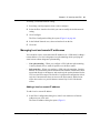
Managing directory service users and groups . . . . . . . . . . . . . . . . . . . . . . . . . . . . . . . 82
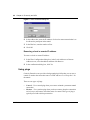
Setting the domain . . . . . . . . . . . . . . . . . . . . . . . . . . . . . . . . . . . . . . . . . . . . . . . . . 83
Setting user name order . . . . . . . . . . . . . . . . . . . . . . . . . . . . . . . . . . . . . . . . . . . . 84
Migrating your database to use unique users and groups by server . . . . . . . . . . . 85
Managing domain users and groups . . . . . . . . . . . . . . . . . . . . . . . . . . . . . . . . . . . 85
Viewing Users and Groups . . . . . . . . . . . . . . . . . . . . . . . . . . . . . . . . . . . . . . . 86
Managing NetWare NDS users and groups . . . . . . . . . . . . . . . . . . . . . . . . . . . . . 86
Setting the context for NDS . . . . . . . . . . . . . . . . . . . . . . . . . . . . . . . . . . . . . . . 87
Managing Novell Bindery users and groups . . . . . . . . . . . . . . . . . . . . . . . . . . . . . 87
Setting the NetWare preferred server . . . . . . . . . . . . . . . . . . . . . . . . . . . . . . . 88
Setting up IP users not using iiLogin . . . . . . . . . . . . . . . . . . . . . . . . . . . . . . . . . . . . . . 88
Creating and removing users and groups . . . . . . . . . . . . . . . . . . . . . . . . . . . . . . . . . . 89
313371-A
Contents
7
Creating a new user or group . . . . . . . . . . . . . . . . . . . . . . . . . . . . . . . . . . . . . . . . 89
Creating a user . . . . . . . . . . . . . . . . . . . . . . . . . . . . . . . . . . . . . . . . . . . . . . . . 90
Creating a group . . . . . . . . . . . . . . . . . . . . . . . . . . . . . . . . . . . . . . . . . . . . . . . 91
Adding a user to a group . . . . . . . . . . . . . . . . . . . . . . . . . . . . . . . . . . . . . . . . . . . . 92
Deleting users and groups . . . . . . . . . . . . . . . . . . . . . . . . . . . . . . . . . . . . . . . . . . . 93
Deleting a user . . . . . . . . . . . . . . . . . . . . . . . . . . . . . . . . . . . . . . . . . . . . . . . . 93
Deleting a group . . . . . . . . . . . . . . . . . . . . . . . . . . . . . . . . . . . . . . . . . . . . . . . 94
Managing users and groups . . . . . . . . . . . . . . . . . . . . . . . . . . . . . . . . . . . . . . . . . . . . . 94
Copying user and group Internet access settings . . . . . . . . . . . . . . . . . . . . . . . . . 95
Viewing effective user access . . . . . . . . . . . . . . . . . . . . . . . . . . . . . . . . . . . . . . . . 97
Defining user and group access . . . . . . . . . . . . . . . . . . . . . . . . . . . . . . . . . . . . . . . . . . 98
Disabling user or group access . . . . . . . . . . . . . . . . . . . . . . . . . . . . . . . . . . . . . . 100
Ignoring group settings option . . . . . . . . . . . . . . . . . . . . . . . . . . . . . . . . . . . . . . . 101
Enabling logging for a user . . . . . . . . . . . . . . . . . . . . . . . . . . . . . . . . . . . . . . . . . 101
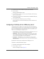
Configuring Internet access . . . . . . . . . . . . . . . . . . . . . . . . . . . . . . . . . . . . . . . . . . . . 102
Defining controlled Internet access . . . . . . . . . . . . . . . . . . . . . . . . . . . . . . . . . . . 104
Overview of configuring Internet access . . . . . . . . . . . . . . . . . . . . . . . . . . . . 105
Adding Internet access . . . . . . . . . . . . . . . . . . . . . . . . . . . . . . . . . . . . . . . . . . . . 107
Removing Internet access . . . . . . . . . . . . . . . . . . . . . . . . . . . . . . . . . . . . . . . . . . 111
Changing Internet access . . . . . . . . . . . . . . . . . . . . . . . . . . . . . . . . . . . . . . . . . . 113
Managing news group access . . . . . . . . . . . . . . . . . . . . . . . . . . . . . . . . . . . . . . . . . . 114
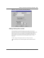
Adding news group access . . . . . . . . . . . . . . . . . . . . . . . . . . . . . . . . . . . . . . . . . 115
Removing news group access . . . . . . . . . . . . . . . . . . . . . . . . . . . . . . . . . . . . . . . 117
Changing news group access . . . . . . . . . . . . . . . . . . . . . . . . . . . . . . . . . . . . . . . 119
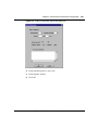
Managing incoming port access . . . . . . . . . . . . . . . . . . . . . . . . . . . . . . . . . . . . . . . . . 120
Adding incoming port access . . . . . . . . . . . . . . . . . . . . . . . . . . . . . . . . . . . . . . . . 121
Removing incoming port access . . . . . . . . . . . . . . . . . . . . . . . . . . . . . . . . . . . . . 123
Changing incoming port access . . . . . . . . . . . . . . . . . . . . . . . . . . . . . . . . . . . . . 125
Managing RAW sockets . . . . . . . . . . . . . . . . . . . . . . . . . . . . . . . . . . . . . . . . . . . . . . . 127
Specifying the message a user sees upon an error . . . . . . . . . . . . . . . . . . . . . . . . . . 129
Creating reports . . . . . . . . . . . . . . . . . . . . . . . . . . . . . . . . . . . . . . . . . . . . . . . . . . . . . 129
Common user and group access examples . . . . . . . . . . . . . . . . . . . . . . . . . . . . . . . . 130
Allowing unlimited access for everyone . . . . . . . . . . . . . . . . . . . . . . . . . . . . . . . . 130
Restricting access to a few sites for everyone . . . . . . . . . . . . . . . . . . . . . . . . . . 132
Allowing access to a few sites . . . . . . . . . . . . . . . . . . . . . . . . . . . . . . . . . . . . . . . 134
Using the Contivity Branch Access Management Software Version 7.20
8
Contents
Managing a remote Contivity unit . . . . . . . . . . . . . . . . . . . . . . . . . . . . . . . . . . . . . . . . 135
Using the Control program to control Internet access times . . . . . . . . . . . . . . . . . . . 136
Using the Control commands . . . . . . . . . . . . . . . . . . . . . . . . . . . . . . . . . . . . . . . 137
Sample Control commands . . . . . . . . . . . . . . . . . . . . . . . . . . . . . . . . . . . . . . 137
Example: Configuring a task in the Windows task scheduler . . . . . . . . . . . . 139
Chapter 4
Internet activity logging . . . . . . . . . . . . . . . . . . . . . . . . . . . . . . . . . . . . . . . 141
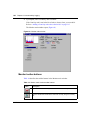
Monitor program overview . . . . . . . . . . . . . . . . . . . . . . . . . . . . . . . . . . . . . . . . . . . . . 141
Monitor toolbar buttons . . . . . . . . . . . . . . . . . . . . . . . . . . . . . . . . . . . . . . . . . . . . 142
Monitoring a Contivity unit . . . . . . . . . . . . . . . . . . . . . . . . . . . . . . . . . . . . . . . . . . 143
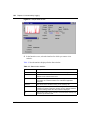
Viewing statistics . . . . . . . . . . . . . . . . . . . . . . . . . . . . . . . . . . . . . . . . . . . . . . . . . 143
Stats toolbar buttons . . . . . . . . . . . . . . . . . . . . . . . . . . . . . . . . . . . . . . . . . . . 146
Stats menu . . . . . . . . . . . . . . . . . . . . . . . . . . . . . . . . . . . . . . . . . . . . . . . . . . 146
Viewing users . . . . . . . . . . . . . . . . . . . . . . . . . . . . . . . . . . . . . . . . . . . . . . . . . . . 147
Users toolbar buttons . . . . . . . . . . . . . . . . . . . . . . . . . . . . . . . . . . . . . . . . . . 148
Users menu . . . . . . . . . . . . . . . . . . . . . . . . . . . . . . . . . . . . . . . . . . . . . . . . . . 149
Users Sort menu . . . . . . . . . . . . . . . . . . . . . . . . . . . . . . . . . . . . . . . . . . . . . . 149
Viewing Web site access . . . . . . . . . . . . . . . . . . . . . . . . . . . . . . . . . . . . . . . . . . . 150
Log toolbar buttons . . . . . . . . . . . . . . . . . . . . . . . . . . . . . . . . . . . . . . . . . . . . 151
Log menu . . . . . . . . . . . . . . . . . . . . . . . . . . . . . . . . . . . . . . . . . . . . . . . . . . . 151
Log Sort menu . . . . . . . . . . . . . . . . . . . . . . . . . . . . . . . . . . . . . . . . . . . . . . . . 152
Viewing diagnostic information . . . . . . . . . . . . . . . . . . . . . . . . . . . . . . . . . . . . . . 152
Performing a Trace . . . . . . . . . . . . . . . . . . . . . . . . . . . . . . . . . . . . . . . . . . . . 154
Monitoring multiple Contivity units . . . . . . . . . . . . . . . . . . . . . . . . . . . . . . . . . . . . . . . 157
Automatic logging . . . . . . . . . . . . . . . . . . . . . . . . . . . . . . . . . . . . . . . . . . . . . . . . . . . . 159
AutoLog toolbar buttons . . . . . . . . . . . . . . . . . . . . . . . . . . . . . . . . . . . . . . . . 160
Enabling Auto Run . . . . . . . . . . . . . . . . . . . . . . . . . . . . . . . . . . . . . . . . . . . . 161
Configuring automatic logging . . . . . . . . . . . . . . . . . . . . . . . . . . . . . . . . . . . . 161
Editing an automatic logging configuration . . . . . . . . . . . . . . . . . . . . . . . . . . 163
Deleting a log from the automatic logging configuration . . . . . . . . . . . . . . . . 163
Exporting log files . . . . . . . . . . . . . . . . . . . . . . . . . . . . . . . . . . . . . . . . . . . . . . . . 164
Managing SYSLOG alarms . . . . . . . . . . . . . . . . . . . . . . . . . . . . . . . . . . . . . . . . . . . . 165
SYSLOG message formats . . . . . . . . . . . . . . . . . . . . . . . . . . . . . . . . . . . . . . . . . 165
Event priorities and messages . . . . . . . . . . . . . . . . . . . . . . . . . . . . . . . . . . . . . . 166
313371-A
Contents
9
Configuring SYSLOG alarms . . . . . . . . . . . . . . . . . . . . . . . . . . . . . . . . . . . . . . . . 170
Managing SNMP alarms . . . . . . . . . . . . . . . . . . . . . . . . . . . . . . . . . . . . . . . . . . . . . . 174
SNMP message formats and trap events . . . . . . . . . . . . . . . . . . . . . . . . . . . . . . 174
Configuring SNMP alarms for trap events . . . . . . . . . . . . . . . . . . . . . . . . . . . . . . 174
Chapter 5
Proxy services . . . . . . . . . . . . . . . . . . . . . . . . . . . . . . . . . . . . . . . . . . . . . . . 179
Understanding proxy servers . . . . . . . . . . . . . . . . . . . . . . . . . . . . . . . . . . . . . . . . . . . 179
Using Setup . . . . . . . . . . . . . . . . . . . . . . . . . . . . . . . . . . . . . . . . . . . . . . . . . . . . . 179
Configuring a Contivity unit as a Web proxy server . . . . . . . . . . . . . . . . . . . . . . . . . . 180
Using a commercial proxy server . . . . . . . . . . . . . . . . . . . . . . . . . . . . . . . . . . . . 182
Enabling Web configuration . . . . . . . . . . . . . . . . . . . . . . . . . . . . . . . . . . . . . . . . . . . . 183
Configuring a workstation to use a Contivity unit as a Web proxy server . . . . . . . . . 184
Configuring a Contivity unit as a DNS proxy server . . . . . . . . . . . . . . . . . . . . . . . . . . 185
Configuring a Contivity unit as a SOCKS proxy server . . . . . . . . . . . . . . . . . . . . . . . 186
Using SOCKS workstations with the Admin program . . . . . . . . . . . . . . . . . . . . . . . . 187
Admin options that do not apply to SOCKS workstations . . . . . . . . . . . . . . . . . . 188
Host name access controls and SOCKS . . . . . . . . . . . . . . . . . . . . . . . . . . . . . . . . . . 188
Configuring socksified applications . . . . . . . . . . . . . . . . . . . . . . . . . . . . . . . . . . . . . . 189
Configuring common SOCKS-enabled software . . . . . . . . . . . . . . . . . . . . . . . . . 189
Third-party socksifying software . . . . . . . . . . . . . . . . . . . . . . . . . . . . . . . . . . . . . 191
Additional SOCKS information . . . . . . . . . . . . . . . . . . . . . . . . . . . . . . . . . . . . . . 191
Chapter 6
Advanced IP configuration . . . . . . . . . . . . . . . . . . . . . . . . . . . . . . . . . . . . . 193
Using Setup . . . . . . . . . . . . . . . . . . . . . . . . . . . . . . . . . . . . . . . . . . . . . . . . . . . . . . . . 193
Changing a unit’s system files . . . . . . . . . . . . . . . . . . . . . . . . . . . . . . . . . . . . . . . . . . 194
Changing a unit’s system settings . . . . . . . . . . . . . . . . . . . . . . . . . . . . . . . . . . . . 194
Changing a unit’s port mappings . . . . . . . . . . . . . . . . . . . . . . . . . . . . . . . . . . . . . 195
Changing a unit’s support hosts . . . . . . . . . . . . . . . . . . . . . . . . . . . . . . . . . . . . . 196
Configuring a static route . . . . . . . . . . . . . . . . . . . . . . . . . . . . . . . . . . . . . . . . . . . . . . 196
Configuring IP forwarding . . . . . . . . . . . . . . . . . . . . . . . . . . . . . . . . . . . . . . . . . . . . . . 199
Enabling IP forwarding . . . . . . . . . . . . . . . . . . . . . . . . . . . . . . . . . . . . . . . . . . . . 199
Enabling IP forwarding for a Contivity unit . . . . . . . . . . . . . . . . . . . . . . . . . . 200
Enabling IP forwarding for two interfaces . . . . . . . . . . . . . . . . . . . . . . . . . . . 201
Using the Contivity Branch Access Management Software Version 7.20
10
Contents
Enabling IP forwarding for two Ethernet interfaces . . . . . . . . . . . . . . . . . . . . 201
Using network address translation (NAT) . . . . . . . . . . . . . . . . . . . . . . . . . . . . . . . . . . 202
Configuring NAT . . . . . . . . . . . . . . . . . . . . . . . . . . . . . . . . . . . . . . . . . . . . . . . . . 203
Disabling address translation . . . . . . . . . . . . . . . . . . . . . . . . . . . . . . . . . . . . 203
Publishing a private server . . . . . . . . . . . . . . . . . . . . . . . . . . . . . . . . . . . . . . . . . 204
Using Dynamic DNS . . . . . . . . . . . . . . . . . . . . . . . . . . . . . . . . . . . . . . . . . . . 204
Configuring Contivity Branch Access to publish a private server . . . . . . . . . 205
Configuring an IP filter . . . . . . . . . . . . . . . . . . . . . . . . . . . . . . . . . . . . . . . . . . . . . . . . 211
Processing a packet through an IP filter . . . . . . . . . . . . . . . . . . . . . . . . . . . . . . . 212
Applying a filter to an interface . . . . . . . . . . . . . . . . . . . . . . . . . . . . . . . . . . . . . . 217
Enabling a Contivity unit as a DHCP server . . . . . . . . . . . . . . . . . . . . . . . . . . . . . . . . 218
Scopes and leases . . . . . . . . . . . . . . . . . . . . . . . . . . . . . . . . . . . . . . . . . . . . . . . 219
Using the DHCP/BootP relay agent feature . . . . . . . . . . . . . . . . . . . . . . . . . . . . 220
Configuring a Contivity unit as a DHCP server . . . . . . . . . . . . . . . . . . . . . . . . . . 222
Using a Contivity unit as a DHCP workstation . . . . . . . . . . . . . . . . . . . . . . . . . . . 228
Configuring the routing information protocol (RIP) . . . . . . . . . . . . . . . . . . . . . . . . . . . 228
Configuring an alias for an interface . . . . . . . . . . . . . . . . . . . . . . . . . . . . . . . . . . . . . 230
Using a demilitarized zone (DMZ) . . . . . . . . . . . . . . . . . . . . . . . . . . . . . . . . . . . . . . . 232
Configuring a Contivity unit to support a DMZ . . . . . . . . . . . . . . . . . . . . . . . . . . . 233
Configuring the interface to support the DMZ . . . . . . . . . . . . . . . . . . . . . . . . 233
Publishing a server . . . . . . . . . . . . . . . . . . . . . . . . . . . . . . . . . . . . . . . . . . . . 234
Deciding whether to enable IP forwarding for your DMZ . . . . . . . . . . . . . . . 234
Chapter 7
Web cache configuration . . . . . . . . . . . . . . . . . . . . . . . . . . . . . . . . . . . . . . 237
Introduction to Web caching . . . . . . . . . . . . . . . . . . . . . . . . . . . . . . . . . . . . . . . . . . . . 237
How the Contivity unit functions as a proxy server . . . . . . . . . . . . . . . . . . . . . . . 237
How the Contivity unit functions as a caching proxy server . . . . . . . . . . . . . . . . 238
How Web caching works . . . . . . . . . . . . . . . . . . . . . . . . . . . . . . . . . . . . . . . . . . . 238
How the Contivity unit expires entries . . . . . . . . . . . . . . . . . . . . . . . . . . . . . . 238
How Web caching works with a user’s local cache . . . . . . . . . . . . . . . . . . . . . . . 239
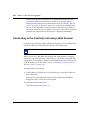
Connecting to the Contivity unit using a Web browser . . . . . . . . . . . . . . . . . . . . . . . . 240
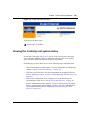
Viewing the Contivity unit system status . . . . . . . . . . . . . . . . . . . . . . . . . . . . . . . . . . 241
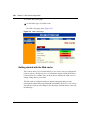
Getting started with the Web cache . . . . . . . . . . . . . . . . . . . . . . . . . . . . . . . . . . . 242
Increasing efficiency . . . . . . . . . . . . . . . . . . . . . . . . . . . . . . . . . . . . . . . . . . . . . . . . . . 243
313371-A
Contents
11
Fine-tuning cache settings . . . . . . . . . . . . . . . . . . . . . . . . . . . . . . . . . . . . . . . . . . 244
Increasing response times . . . . . . . . . . . . . . . . . . . . . . . . . . . . . . . . . . . . . . 244
Increasing bandwidth savings . . . . . . . . . . . . . . . . . . . . . . . . . . . . . . . . . . . . 244
Deciding how long to run an experiment . . . . . . . . . . . . . . . . . . . . . . . . . . . . 245
Selecting a cache level . . . . . . . . . . . . . . . . . . . . . . . . . . . . . . . . . . . . . . . . . . . . 245
How cache levels are defined . . . . . . . . . . . . . . . . . . . . . . . . . . . . . . . . . . . . 246
Expiration percent . . . . . . . . . . . . . . . . . . . . . . . . . . . . . . . . . . . . . . . . . . . . . 246
Minimum expiration time . . . . . . . . . . . . . . . . . . . . . . . . . . . . . . . . . . . . . . . . 247
Special Web requests . . . . . . . . . . . . . . . . . . . . . . . . . . . . . . . . . . . . . . . . . . 248
Error message . . . . . . . . . . . . . . . . . . . . . . . . . . . . . . . . . . . . . . . . . . . . . . . . 248
Predefined cache levels default values . . . . . . . . . . . . . . . . . . . . . . . . . . . . . . . . 249
Creating a custom cache level . . . . . . . . . . . . . . . . . . . . . . . . . . . . . . . . . . . . . . 250
Interpreting statistics . . . . . . . . . . . . . . . . . . . . . . . . . . . . . . . . . . . . . . . . . . . . . . . . . 251
Using statistics to fine-tune cache settings . . . . . . . . . . . . . . . . . . . . . . . . . . . . . 251
Viewing why requests are not sent from the cache . . . . . . . . . . . . . . . . . . . . . . . 252
Limiting the size of a cached entry . . . . . . . . . . . . . . . . . . . . . . . . . . . . . . . . . . . 254
Setting options for special Web requests . . . . . . . . . . . . . . . . . . . . . . . . . . . . . . 255
CGI requests . . . . . . . . . . . . . . . . . . . . . . . . . . . . . . . . . . . . . . . . . . . . . . . . . 255
Query requests . . . . . . . . . . . . . . . . . . . . . . . . . . . . . . . . . . . . . . . . . . . . . . . 255
“No-cache” requests . . . . . . . . . . . . . . . . . . . . . . . . . . . . . . . . . . . . . . . . . . . 256
Setting the action the cache performs when a Web server error occurs . . . . . . . 258
Resetting cache statistics . . . . . . . . . . . . . . . . . . . . . . . . . . . . . . . . . . . . . . . . . . 258
Managing cookies . . . . . . . . . . . . . . . . . . . . . . . . . . . . . . . . . . . . . . . . . . . . . . . . . . . 259
Establishing a cookie management policy . . . . . . . . . . . . . . . . . . . . . . . . . . . . . . 260
Managing cookies for all unconfigured Web sites . . . . . . . . . . . . . . . . . . . . . . . . 261
Managing cookies for a particular Web site . . . . . . . . . . . . . . . . . . . . . . . . . . . . . 262
Enabling cookies for a particular Web site . . . . . . . . . . . . . . . . . . . . . . . . . . . . . . 262
Sorting the Web sites list . . . . . . . . . . . . . . . . . . . . . . . . . . . . . . . . . . . . . . . . . . . 263
Managing Web site access . . . . . . . . . . . . . . . . . . . . . . . . . . . . . . . . . . . . . . . . . . . . 264
Blocking Web site access . . . . . . . . . . . . . . . . . . . . . . . . . . . . . . . . . . . . . . . . . . 265
Blocking access to all unconfigured Web sites . . . . . . . . . . . . . . . . . . . . . . . 265
Blocking access to a particular Web site . . . . . . . . . . . . . . . . . . . . . . . . . . . . 266
Setting Web site activity display options . . . . . . . . . . . . . . . . . . . . . . . . . . . . . . . 266
Configuring Web site display options . . . . . . . . . . . . . . . . . . . . . . . . . . . . . . . . . . 267
Bypassing the cache for a Web site . . . . . . . . . . . . . . . . . . . . . . . . . . . . . . . . . . 267
Using the Contivity Branch Access Management Software Version 7.20
12
Contents
Saving and Restoring Web site configuration . . . . . . . . . . . . . . . . . . . . . . . . . . . . . . 269
Refreshing cache entries . . . . . . . . . . . . . . . . . . . . . . . . . . . . . . . . . . . . . . . . . . . . . . 270
Setting active refresh options . . . . . . . . . . . . . . . . . . . . . . . . . . . . . . . . . . . . . . . 270
Interpreting active refresh statistics . . . . . . . . . . . . . . . . . . . . . . . . . . . . . . . . . . . 271
Troubleshooting the Web cache . . . . . . . . . . . . . . . . . . . . . . . . . . . . . . . . . . . . . . . . . 272
I requested a Web site, but there was no response. . . . . . . . . . . . . . . . . . . . . . . 272
I blocked a site, but it still opens in a user’s Web browser. . . . . . . . . . . . . . . . . . 272
I requested a Web page, but the content looks outdated. . . . . . . . . . . . . . . . . . . 273
I requested a Web page and the originating Web server takes
a long time to respond . . . . . . . . . . . . . . . . . . . . . . . . . . . . . . . . . . . . . . . . . . . . .273
I am not able to configure a personalized Web page. . . . . . . . . . . . . . . . . . . . . . 274
I logged on to a Web site, but I am prompted to log on again. . . . . . . . . . . . . . . 274
I added an item to my online shopping cart, but it’s still empty. . . . . . . . . . . . . . . 274
Chapter 8
Advanced communications configuration . . . . . . . . . . . . . . . . . . . . . . . . 277
Configuring advanced communication settings for an ISDN connection . . . . . . . . . . 277
Adding a backup phone number . . . . . . . . . . . . . . . . . . . . . . . . . . . . . . . . . . . . . 278
Changing ISP connection settings . . . . . . . . . . . . . . . . . . . . . . . . . . . . . . . . . . . . 279
Setting the inactivity timeout . . . . . . . . . . . . . . . . . . . . . . . . . . . . . . . . . . . . . . . . 280
Configuring advanced ISDN features . . . . . . . . . . . . . . . . . . . . . . . . . . . . . . . . . 280
Enabling bandwidth on demand . . . . . . . . . . . . . . . . . . . . . . . . . . . . . . . . . . 281
Configuring voice call options . . . . . . . . . . . . . . . . . . . . . . . . . . . . . . . . . . . . 282
Configuring incoming data call options . . . . . . . . . . . . . . . . . . . . . . . . . . . . . 283
Configuring advanced communication settings for a dial-up connection . . . . . . . . . . 284
Adding a backup phone number . . . . . . . . . . . . . . . . . . . . . . . . . . . . . . . . . . . . . 285
Changing IP address settings . . . . . . . . . . . . . . . . . . . . . . . . . . . . . . . . . . . . . . . 286
Setting the inactivity timeout . . . . . . . . . . . . . . . . . . . . . . . . . . . . . . . . . . . . . . . . 286
Configuring the modem speaker . . . . . . . . . . . . . . . . . . . . . . . . . . . . . . . . . . . . . 286
Configuring a modem script . . . . . . . . . . . . . . . . . . . . . . . . . . . . . . . . . . . . . . . . . 288
Configuring dual-analog modem settings . . . . . . . . . . . . . . . . . . . . . . . . . . . . . . 288
Setting the number of lines . . . . . . . . . . . . . . . . . . . . . . . . . . . . . . . . . . . . . . 288
Enabling bandwidth on demand . . . . . . . . . . . . . . . . . . . . . . . . . . . . . . . . . . 289
Configuring advanced communication settings for a T1 connection . . . . . . . . . . . . . 290
Configuring advanced communication settings for an E1 connection . . . . . . . . . . . . 292
313371-A
Contents
13
Configuring advanced communication settings for a PPPoE connection . . . . . . . . . 294
Chapter 9
IPX configuration and support . . . . . . . . . . . . . . . . . . . . . . . . . . . . . . . . . . 297
Using Contivity as an IPX-to-IP gateway . . . . . . . . . . . . . . . . . . . . . . . . . . . . . . . . . . 297
Security considerations . . . . . . . . . . . . . . . . . . . . . . . . . . . . . . . . . . . . . . . . . . . . 297
Performance considerations . . . . . . . . . . . . . . . . . . . . . . . . . . . . . . . . . . . . . . . . 298
Normal delays . . . . . . . . . . . . . . . . . . . . . . . . . . . . . . . . . . . . . . . . . . . . . . . . 298
Number of simultaneous connections . . . . . . . . . . . . . . . . . . . . . . . . . . . . . . 298
When to consider a higher-speed connection . . . . . . . . . . . . . . . . . . . . . . . . 299
Configuring IPX workstations to use a new unit name . . . . . . . . . . . . . . . . . . . . . . . . 299
Configuring IPX frame types . . . . . . . . . . . . . . . . . . . . . . . . . . . . . . . . . . . . . . . . . . . 301
Resolving Winsock conflicts . . . . . . . . . . . . . . . . . . . . . . . . . . . . . . . . . . . . . . . . . . . . 302
16-bit Winsocks . . . . . . . . . . . . . . . . . . . . . . . . . . . . . . . . . . . . . . . . . . . . . . . 302
32-bit Winsocks . . . . . . . . . . . . . . . . . . . . . . . . . . . . . . . . . . . . . . . . . . . . . . . 303
Winsock 1.1 and Winsock 2.0 . . . . . . . . . . . . . . . . . . . . . . . . . . . . . . . . . . . . . . . 303
Using multiple versions of Winsock . . . . . . . . . . . . . . . . . . . . . . . . . . . . . . . . . . . 303
Using multiple 16-bit Winsocks . . . . . . . . . . . . . . . . . . . . . . . . . . . . . . . . . . . 304
Using multiple 32-bit Winsocks . . . . . . . . . . . . . . . . . . . . . . . . . . . . . . . . . . . 304
Winsock files installed . . . . . . . . . . . . . . . . . . . . . . . . . . . . . . . . . . . . . . . . . . . . . 305
Windows 3.x . . . . . . . . . . . . . . . . . . . . . . . . . . . . . . . . . . . . . . . . . . . . . . . . . 305
Windows 95, Windows 98, and Windows Me . . . . . . . . . . . . . . . . . . . . . . . . 305
Windows 95 . . . . . . . . . . . . . . . . . . . . . . . . . . . . . . . . . . . . . . . . . . . . . . . . . . 306
Windows NT 4.0 . . . . . . . . . . . . . . . . . . . . . . . . . . . . . . . . . . . . . . . . . . . . . . 306
Resolving Winsock conflicts during installation . . . . . . . . . . . . . . . . . . . . . . . . . . 306
IP filters and Winsock compatibility . . . . . . . . . . . . . . . . . . . . . . . . . . . . . . . . . . . 307
Configuring the Contivity unit in a multiple-unit environment . . . . . . . . . . . . . . . . . . . 307
Configuring fault tolerance and automatic user load balancing . . . . . . . . . . . . . . 308
Configuring multiple default sets . . . . . . . . . . . . . . . . . . . . . . . . . . . . . . . . . . . . . 309
Installing multiple Contivity units . . . . . . . . . . . . . . . . . . . . . . . . . . . . . . . . . . . . . . . . 312
Tips for installing multiple Contivity units . . . . . . . . . . . . . . . . . . . . . . . . . . . . . . . 312
Using the Contivity Branch Access Management Software Version 7.20
14
Contents
Chapter 10
Contivity unit configuration, support, and diagnostics . . . . . . . . . . . . . . 313
Restarting a Contivity unit . . . . . . . . . . . . . . . . . . . . . . . . . . . . . . . . . . . . . . . . . . . . . 313
Identifying the login workstation . . . . . . . . . . . . . . . . . . . . . . . . . . . . . . . . . . . . . . . . . 314
Adding a Contivity unit to the selection list . . . . . . . . . . . . . . . . . . . . . . . . . . . . . . . . . 315
Understanding the name server list order . . . . . . . . . . . . . . . . . . . . . . . . . . . . . . . . . 316
Saving and restoring unit configurations . . . . . . . . . . . . . . . . . . . . . . . . . . . . . . . . . . 317
Backing up a unit configuration to disk . . . . . . . . . . . . . . . . . . . . . . . . . . . . . . . . 317
Restoring a unit configuration from disk . . . . . . . . . . . . . . . . . . . . . . . . . . . . . . . 318
Changing the unit configuration . . . . . . . . . . . . . . . . . . . . . . . . . . . . . . . . . . . . . . . . . 319
Changing your ISP . . . . . . . . . . . . . . . . . . . . . . . . . . . . . . . . . . . . . . . . . . . . . . . 320
Changing registration information . . . . . . . . . . . . . . . . . . . . . . . . . . . . . . . . . . . . 322
Changing a unit’s password . . . . . . . . . . . . . . . . . . . . . . . . . . . . . . . . . . . . . . . . . 323
Changing a unit’s name . . . . . . . . . . . . . . . . . . . . . . . . . . . . . . . . . . . . . . . . . . . . 325
Changing a unit’s time, date, or time zone . . . . . . . . . . . . . . . . . . . . . . . . . . . . . 325
Selecting additional support options . . . . . . . . . . . . . . . . . . . . . . . . . . . . . . . . . . . . . 328
Enabling diagnostic IP tools . . . . . . . . . . . . . . . . . . . . . . . . . . . . . . . . . . . . . . . . . . . . 329
Defining the SNMP community string for get requests . . . . . . . . . . . . . . . . . . . . 331
Testing connections . . . . . . . . . . . . . . . . . . . . . . . . . . . . . . . . . . . . . . . . . . . . . . . . . . 332
Testing the connection to the Internet . . . . . . . . . . . . . . . . . . . . . . . . . . . . . . . . . 332
Testing the connection to a host . . . . . . . . . . . . . . . . . . . . . . . . . . . . . . . . . . . . . 333
Testing the response time of a host . . . . . . . . . . . . . . . . . . . . . . . . . . . . . . . 334
Tracing the route to a host . . . . . . . . . . . . . . . . . . . . . . . . . . . . . . . . . . . . . . 336
Testing the echo port of a host . . . . . . . . . . . . . . . . . . . . . . . . . . . . . . . . . . . 338
Setting host connection test options . . . . . . . . . . . . . . . . . . . . . . . . . . . . . . . 341
Appendix A
Troubleshooting and error messages . . . . . . . . . . . . . . . . . . . . . . . . . . . . 343
Viewing a Contivity unit’s serial number . . . . . . . . . . . . . . . . . . . . . . . . . . . . . . . . . . . 343
Viewing system logs and entries . . . . . . . . . . . . . . . . . . . . . . . . . . . . . . . . . . . . . . . . 344
Viewing system files in Setup . . . . . . . . . . . . . . . . . . . . . . . . . . . . . . . . . . . . . . . 344
Viewing unit log information . . . . . . . . . . . . . . . . . . . . . . . . . . . . . . . . . . . . . 344
Viewing a unit’s users . . . . . . . . . . . . . . . . . . . . . . . . . . . . . . . . . . . . . . . . . . 344
Viewing a unit’s update history . . . . . . . . . . . . . . . . . . . . . . . . . . . . . . . . . . . 345
313371-A
Contents
15
Managing system files through a Web browser . . . . . . . . . . . . . . . . . . . . . . . . . . 345
Connecting to the Contivity unit using a Web browser . . . . . . . . . . . . . . . . . 345
Viewing a unit’s log files . . . . . . . . . . . . . . . . . . . . . . . . . . . . . . . . . . . . . . . . 347
Viewing a unit’s update history . . . . . . . . . . . . . . . . . . . . . . . . . . . . . . . . . . . 347
Changing a unit’s system settings file . . . . . . . . . . . . . . . . . . . . . . . . . . . . . . 347
Changing a unit’s port mappings . . . . . . . . . . . . . . . . . . . . . . . . . . . . . . . . . . 348
Changing a unit’s hosts . . . . . . . . . . . . . . . . . . . . . . . . . . . . . . . . . . . . . . . . . 348
IP workstation error messages . . . . . . . . . . . . . . . . . . . . . . . . . . . . . . . . . . . . . . . . . . 348
Common questions and answers . . . . . . . . . . . . . . . . . . . . . . . . . . . . . . . . . . . . . . . . 349
Glossary . . . . . . . . . . . . . . . . . . . . . . . . . . . . . . . . . . . . . . . . . . . . . . . . . . . . 351
Index . . . . . . . . . . . . . . . . . . . . . . . . . . . . . . . . . . . . . . . . . . . . . . . . . . . . . . . 369
Using the Contivity Branch Access Management Software Version 7.20
16
Contents
313371-A
17
Figures
Figure 1
Connecting the Contivity unit in a network . . . . . . . . . . . . . . . . . . . . . . . . 32
Figure 2
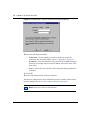
IPsec Configuration dialog box . . . . . . . . . . . . . . . . . . . . . . . . . . . . . . . . . 40
Figure 3
Enter IP Address dialog box . . . . . . . . . . . . . . . . . . . . . . . . . . . . . . . . . . . 42
Figure 4
Pings dialog box . . . . . . . . . . . . . . . . . . . . . . . . . . . . . . . . . . . . . . . . . . . . 45
Figure 5
Ping Configuration dialog box . . . . . . . . . . . . . . . . . . . . . . . . . . . . . . . . . . 46
Figure 6
Select Connection Type dialog box . . . . . . . . . . . . . . . . . . . . . . . . . . . . . 48
Figure 7
Select Connection Device dialog box . . . . . . . . . . . . . . . . . . . . . . . . . . . . 48
Figure 8
Select Type of Connections dialog box . . . . . . . . . . . . . . . . . . . . . . . . . . 49
Figure 9
IPsec Configuration dialog box . . . . . . . . . . . . . . . . . . . . . . . . . . . . . . . . . 49
Figure 10
IPsec Configuration dialog box . . . . . . . . . . . . . . . . . . . . . . . . . . . . . . . . . 51
Figure 11
Monitor Connection dialog box . . . . . . . . . . . . . . . . . . . . . . . . . . . . . . . . . 52
Figure 12
Enter Monitor / Control Connection Information dialog box . . . . . . . . . . . 52
Figure 13
IPsec Configuration dialog box . . . . . . . . . . . . . . . . . . . . . . . . . . . . . . . . . 54
Figure 14
Monitor Connection dialog box . . . . . . . . . . . . . . . . . . . . . . . . . . . . . . . . . 55
Figure 15
Enter Monitor / Control Connection Information dialog box . . . . . . . . . . . 55
Figure 16
Select Connection Type dialog box . . . . . . . . . . . . . . . . . . . . . . . . . . . . . 64
Figure 17
Select Connection Device dialog box . . . . . . . . . . . . . . . . . . . . . . . . . . . . 65
Figure 18
Select Type of Connection dialog box . . . . . . . . . . . . . . . . . . . . . . . . . . . 65
Figure 19
IPsec Configuration dialog box . . . . . . . . . . . . . . . . . . . . . . . . . . . . . . . . . 66
Figure 20
Monitor Connection dialog box . . . . . . . . . . . . . . . . . . . . . . . . . . . . . . . . . 67
Figure 21
Enter Monitor / Control Connection Information dialog box . . . . . . . . . . . 67
Figure 22
IPsec Configuration dialog box . . . . . . . . . . . . . . . . . . . . . . . . . . . . . . . . . 68
Figure 23
IPsec Configuration dialog box . . . . . . . . . . . . . . . . . . . . . . . . . . . . . . . . . 72
Figure 24
Enter Monitor / Control Connection Information dialog box . . . . . . . . . . . 74
Figure 25
Default User icon . . . . . . . . . . . . . . . . . . . . . . . . . . . . . . . . . . . . . . . . . . . 81
Figure 26
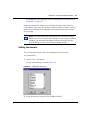
Set Domain dialog box . . . . . . . . . . . . . . . . . . . . . . . . . . . . . . . . . . . . . . . 83
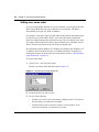
Figure 27
Set User Name Order dialog box . . . . . . . . . . . . . . . . . . . . . . . . . . . . . . . 84
Figure 28
Prompt to use selected user as a template . . . . . . . . . . . . . . . . . . . . . . . 90
Figure 29
Create a User dialog box . . . . . . . . . . . . . . . . . . . . . . . . . . . . . . . . . . . . . 90
Using the Contivity Branch Access Management Software Version 7.20
18
Figures
Figure 30
Prompt to use selected group as a template . . . . . . . . . . . . . . . . . . . . . . 91
Figure 31
Create a Group dialog box . . . . . . . . . . . . . . . . . . . . . . . . . . . . . . . . . . . . 91
Figure 32
Delete user confirmation message box . . . . . . . . . . . . . . . . . . . . . . . . . . 93
Figure 33
Delete group confirmation message box . . . . . . . . . . . . . . . . . . . . . . . . . 94
Figure 34
Copy user confirmation message box . . . . . . . . . . . . . . . . . . . . . . . . . . . 96
Figure 35
Copy group confirmation message box . . . . . . . . . . . . . . . . . . . . . . . . . . 96
Figure 36
Effective Settings of User dialog box . . . . . . . . . . . . . . . . . . . . . . . . . . . . 97
Figure 37
Change Settings of User dialog box . . . . . . . . . . . . . . . . . . . . . . . . . . . . 100
Figure 38
Change User Access dialog box . . . . . . . . . . . . . . . . . . . . . . . . . . . . . . 102
Figure 39
Change Settings of User dialog box . . . . . . . . . . . . . . . . . . . . . . . . . . . . 108
Figure 40
Change Internet Access dialog box . . . . . . . . . . . . . . . . . . . . . . . . . . . . 109
Figure 41
Add Internet Access dialog box . . . . . . . . . . . . . . . . . . . . . . . . . . . . . . . 109
Figure 42
Change Settings of User dialog box . . . . . . . . . . . . . . . . . . . . . . . . . . . . 111
Figure 43
Change Internet Access dialog box . . . . . . . . . . . . . . . . . . . . . . . . . . . . 112
Figure 44
Delete access confirmation message box . . . . . . . . . . . . . . . . . . . . . . . 112
Figure 45
Change Settings of User dialog box . . . . . . . . . . . . . . . . . . . . . . . . . . . . 113
Figure 46
Change Internet Access dialog box . . . . . . . . . . . . . . . . . . . . . . . . . . . . 114
Figure 47
Change Settings of User dialog box . . . . . . . . . . . . . . . . . . . . . . . . . . . . 115
Figure 48
Change News Groups dialog box . . . . . . . . . . . . . . . . . . . . . . . . . . . . . . 116
Figure 49
Add News Group dialog box . . . . . . . . . . . . . . . . . . . . . . . . . . . . . . . . . . 116
Figure 50
Change Settings of User dialog box . . . . . . . . . . . . . . . . . . . . . . . . . . . . 118
Figure 51
Delete news group confirmation message box . . . . . . . . . . . . . . . . . . . . 118
Figure 52
Change Settings of User dialog box . . . . . . . . . . . . . . . . . . . . . . . . . . . . 119
Figure 53
Change News Group dialog box . . . . . . . . . . . . . . . . . . . . . . . . . . . . . . . 120
Figure 54
Change Settings of User dialog box . . . . . . . . . . . . . . . . . . . . . . . . . . . . 121
Figure 55
Change Incoming Ports dialog box . . . . . . . . . . . . . . . . . . . . . . . . . . . . . 122
Figure 56
Add Incoming Port dialog box . . . . . . . . . . . . . . . . . . . . . . . . . . . . . . . . . 122
Figure 57
Change Settings of User dialog box . . . . . . . . . . . . . . . . . . . . . . . . . . . . 124
Figure 58
Delete incoming port confirmation message box . . . . . . . . . . . . . . . . . . 125
Figure 59
Change Settings of User dialog box . . . . . . . . . . . . . . . . . . . . . . . . . . . . 126
Figure 60
Change Incoming Port dialog box . . . . . . . . . . . . . . . . . . . . . . . . . . . . . 127
Figure 61
Change Settings of User dialog box . . . . . . . . . . . . . . . . . . . . . . . . . . . . 128
Figure 62
Select Reports dialog box . . . . . . . . . . . . . . . . . . . . . . . . . . . . . . . . . . . . 129
Figure 63
Change User Access dialog box . . . . . . . . . . . . . . . . . . . . . . . . . . . . . . 131
Figure 64
Change Internet access to deny access to a site example . . . . . . . . . . . 132
313371-A
Figures
19
Figure 65
Restrict Internet access example . . . . . . . . . . . . . . . . . . . . . . . . . . . . . . 133
Figure 66
Allow Internet access example . . . . . . . . . . . . . . . . . . . . . . . . . . . . . . . . 134
Figure 67
Control help screen . . . . . . . . . . . . . . . . . . . . . . . . . . . . . . . . . . . . . . . . 137
Figure 68
Monitor main window . . . . . . . . . . . . . . . . . . . . . . . . . . . . . . . . . . . . . . . 142
Figure 69
Sample Stats window . . . . . . . . . . . . . . . . . . . . . . . . . . . . . . . . . . . . . . . 144
Figure 70
Sample Users window . . . . . . . . . . . . . . . . . . . . . . . . . . . . . . . . . . . . . . 148
Figure 71
Sample Log window . . . . . . . . . . . . . . . . . . . . . . . . . . . . . . . . . . . . . . . . 150
Figure 72
Sample Diag window . . . . . . . . . . . . . . . . . . . . . . . . . . . . . . . . . . . . . . . 153
Figure 73
Trace dialog box . . . . . . . . . . . . . . . . . . . . . . . . . . . . . . . . . . . . . . . . . . . 155
Figure 74
Sample trace results file . . . . . . . . . . . . . . . . . . . . . . . . . . . . . . . . . . . . . 156
Figure 75
Multiple Contivity units window . . . . . . . . . . . . . . . . . . . . . . . . . . . . . . . . 158
Figure 76
AutoLog window . . . . . . . . . . . . . . . . . . . . . . . . . . . . . . . . . . . . . . . . . . . 160
Figure 77
Event Information dialog box . . . . . . . . . . . . . . . . . . . . . . . . . . . . . . . . . 162
Figure 78
Sample SYSLOG output . . . . . . . . . . . . . . . . . . . . . . . . . . . . . . . . . . . . . 165
Figure 79
Alarms dialog box . . . . . . . . . . . . . . . . . . . . . . . . . . . . . . . . . . . . . . . . . . 171
Figure 80
Enter SYSLOG Host dialog box . . . . . . . . . . . . . . . . . . . . . . . . . . . . . . . 171
Figure 81
Sample SYSLOG Output . . . . . . . . . . . . . . . . . . . . . . . . . . . . . . . . . . . . 173
Figure 82
Alarms dialog box . . . . . . . . . . . . . . . . . . . . . . . . . . . . . . . . . . . . . . . . . . 175
Figure 83
Enter SNMP Host dialog box . . . . . . . . . . . . . . . . . . . . . . . . . . . . . . . . . 175
Figure 84
Services dialog box . . . . . . . . . . . . . . . . . . . . . . . . . . . . . . . . . . . . . . . . 181
Figure 85
WEB Proxy Configuration dialog box . . . . . . . . . . . . . . . . . . . . . . . . . . . 181
Figure 86
WEB Server Configuration dialog box . . . . . . . . . . . . . . . . . . . . . . . . . . 183
Figure 87
Services dialog box . . . . . . . . . . . . . . . . . . . . . . . . . . . . . . . . . . . . . . . . 186
Figure 88
Services dialog box . . . . . . . . . . . . . . . . . . . . . . . . . . . . . . . . . . . . . . . . 187
Figure 89
Static Routes dialog box . . . . . . . . . . . . . . . . . . . . . . . . . . . . . . . . . . . . . 198
Figure 90
Static Route Configuration dialog box . . . . . . . . . . . . . . . . . . . . . . . . . . 198
Figure 91
Other Settings dialog box . . . . . . . . . . . . . . . . . . . . . . . . . . . . . . . . . . . . 200
Figure 92
Interface Configuration dialog box . . . . . . . . . . . . . . . . . . . . . . . . . . . . . 204
Figure 93
Server Publication dialog box . . . . . . . . . . . . . . . . . . . . . . . . . . . . . . . . . 206
Figure 94
Server Publication Configuration dialog box . . . . . . . . . . . . . . . . . . . . . . 206
Figure 95
Example: Publishing an SMTP server . . . . . . . . . . . . . . . . . . . . . . . . . . 208
Figure 96
Other Settings dialog box . . . . . . . . . . . . . . . . . . . . . . . . . . . . . . . . . . . . 209
Figure 97
Example: Publishing a server for NetMeeting . . . . . . . . . . . . . . . . . . . . . 211
Figure 98
Interface Filter Configuration dialog box . . . . . . . . . . . . . . . . . . . . . . . . . 213
Figure 99
Filter Configuration dialog box . . . . . . . . . . . . . . . . . . . . . . . . . . . . . . . . 214
Using the Contivity Branch Access Management Software Version 7.20
20
Figures
Figure 100 Rule Configuration dialog box . . . . . . . . . . . . . . . . . . . . . . . . . . . . . . . . 215
Figure 101 Interface Filter Configuration dialog box . . . . . . . . . . . . . . . . . . . . . . . . . 218
Figure 102 Services dialog box . . . . . . . . . . . . . . . . . . . . . . . . . . . . . . . . . . . . . . . . 221
Figure 103 DHCP Configuration dialog box . . . . . . . . . . . . . . . . . . . . . . . . . . . . . . . 222
Figure 104 Services dialog box . . . . . . . . . . . . . . . . . . . . . . . . . . . . . . . . . . . . . . . . 223
Figure 105 DHCP Configuration dialog box . . . . . . . . . . . . . . . . . . . . . . . . . . . . . . . 224
Figure 106 Scope Configuration dialog box . . . . . . . . . . . . . . . . . . . . . . . . . . . . . . . 225
Figure 107 Enter Excluded Addresses dialog box . . . . . . . . . . . . . . . . . . . . . . . . . . 226
Figure 108 Enter Server Address dialog box . . . . . . . . . . . . . . . . . . . . . . . . . . . . . . 227
Figure 109 RIP’s dialog box . . . . . . . . . . . . . . . . . . . . . . . . . . . . . . . . . . . . . . . . . . . 229
Figure 110 Enter Alias Name and IP Address and Select Interface dialog box . . . . 231
Figure 111 Interface Configuration dialog box . . . . . . . . . . . . . . . . . . . . . . . . . . . . . 232
Figure 112 Enter IP Information for Interface dialog box . . . . . . . . . . . . . . . . . . . . . 234
Figure 113 Enter IP Information for Interface dialog box . . . . . . . . . . . . . . . . . . . . . 235
Figure 114 Server Publication dialog box . . . . . . . . . . . . . . . . . . . . . . . . . . . . . . . . . 236
Figure 115 Instant Internet home page . . . . . . . . . . . . . . . . . . . . . . . . . . . . . . . . . . . 241
Figure 116 Web Cache page . . . . . . . . . . . . . . . . . . . . . . . . . . . . . . . . . . . . . . . . . . 242
Figure 117 ISDN Configuration dialog box . . . . . . . . . . . . . . . . . . . . . . . . . . . . . . . . 278
Figure 118 ISDN Configuration (advanced) dialog box . . . . . . . . . . . . . . . . . . . . . . 281
Figure 119 Dialup Configuration dialog box . . . . . . . . . . . . . . . . . . . . . . . . . . . . . . . 284
Figure 120 Dialup Configuration (dual-analog) dialog box . . . . . . . . . . . . . . . . . . . . 285
Figure 121 Dialup Configuration (advanced) dialog box . . . . . . . . . . . . . . . . . . . . . . 287
Figure 122 T1 Configuration dialog box . . . . . . . . . . . . . . . . . . . . . . . . . . . . . . . . . . 290
Figure 123 T1 Advanced Configuration dialog box . . . . . . . . . . . . . . . . . . . . . . . . . . 291
Figure 124 E1 Configuration dialog box . . . . . . . . . . . . . . . . . . . . . . . . . . . . . . . . . . 292
Figure 125 E1 Advanced Configuration dialog box . . . . . . . . . . . . . . . . . . . . . . . . . 293
Figure 126 PPPoE Configuration dialog box . . . . . . . . . . . . . . . . . . . . . . . . . . . . . . 294
Figure 127 PPPoE Configuration (advanced) dialog box . . . . . . . . . . . . . . . . . . . . . 295
Figure 128 Windows 95 Run dialog box . . . . . . . . . . . . . . . . . . . . . . . . . . . . . . . . . . 300
Figure 129 Instant Internet Units dialog box . . . . . . . . . . . . . . . . . . . . . . . . . . . . . . . 300
Figure 130 Select IPX Frame Types dialog box . . . . . . . . . . . . . . . . . . . . . . . . . . . . 301
Figure 131 Restarting Instant Internet dialog box . . . . . . . . . . . . . . . . . . . . . . . . . . . 313
Figure 132 iiLogin icon . . . . . . . . . . . . . . . . . . . . . . . . . . . . . . . . . . . . . . . . . . . . . . . 314
Figure 133 iiLogin Connected as username dialog box . . . . . . . . . . . . . . . . . . . . . . 314
Figure 134 Instant Internet Units dialog box . . . . . . . . . . . . . . . . . . . . . . . . . . . . . . . 315
313371-A
Figures
21
Figure 135 Enter Unit’s IP Address dialog box . . . . . . . . . . . . . . . . . . . . . . . . . . . . . 316
Figure 136 Backup Setup Configuration dialog box . . . . . . . . . . . . . . . . . . . . . . . . . 317
Figure 137 Restore Setup Configuration dialog box . . . . . . . . . . . . . . . . . . . . . . . . . 318
Figure 138 Prompt to restore users and groups . . . . . . . . . . . . . . . . . . . . . . . . . . . . 319
Figure 139 Dialup Configuration dialog box . . . . . . . . . . . . . . . . . . . . . . . . . . . . . . . 321
Figure 140 ISDN Configuration dialog box . . . . . . . . . . . . . . . . . . . . . . . . . . . . . . . . 322
Figure 141 Registration Information dialog box . . . . . . . . . . . . . . . . . . . . . . . . . . . . 323
Figure 142 Change Password dialog box . . . . . . . . . . . . . . . . . . . . . . . . . . . . . . . . . 324
Figure 143 Unit Name dialog box . . . . . . . . . . . . . . . . . . . . . . . . . . . . . . . . . . . . . . . 325
Figure 144 Unit Time dialog box . . . . . . . . . . . . . . . . . . . . . . . . . . . . . . . . . . . . . . . . 326
Figure 145 Time Zone dialog box . . . . . . . . . . . . . . . . . . . . . . . . . . . . . . . . . . . . . . . 327
Figure 146 Other Settings dialog box . . . . . . . . . . . . . . . . . . . . . . . . . . . . . . . . . . . . 328
Figure 147 Services dialog box . . . . . . . . . . . . . . . . . . . . . . . . . . . . . . . . . . . . . . . . 330
Figure 148 SNMP Configuration dialog box . . . . . . . . . . . . . . . . . . . . . . . . . . . . . . . 332
Figure 149 Tools main window . . . . . . . . . . . . . . . . . . . . . . . . . . . . . . . . . . . . . . . . . 334
Figure 150 Ping test . . . . . . . . . . . . . . . . . . . . . . . . . . . . . . . . . . . . . . . . . . . . . . . . . 336
Figure 151 Trace test . . . . . . . . . . . . . . . . . . . . . . . . . . . . . . . . . . . . . . . . . . . . . . . . 338
Figure 152 Stress test . . . . . . . . . . . . . . . . . . . . . . . . . . . . . . . . . . . . . . . . . . . . . . . . 340
Figure 153 Options dialog box in Tools . . . . . . . . . . . . . . . . . . . . . . . . . . . . . . . . . . . 341
Figure 154 About Instant Internet Setup dialog box, Serial Number box . . . . . . . . . 343
Figure 155 Instant Internet home page . . . . . . . . . . . . . . . . . . . . . . . . . . . . . . . . . . . 346
Figure 156 Instant Internet System Administration page . . . . . . . . . . . . . . . . . . . . . 346
Using the Contivity Branch Access Management Software Version 7.20
22
Figures
313371-A
23
Tables
Table 1
Services Contivity Branch Access provides . . . . . . . . . . . . . . . . . . . . . . . 35
Table 2
Phase 1 main mode states . . . . . . . . . . . . . . . . . . . . . . . . . . . . . . . . . . . . 77
Table 3
Phase 1 aggressive mode states . . . . . . . . . . . . . . . . . . . . . . . . . . . . . . . 77
Table 4
Phase 2 main mode states . . . . . . . . . . . . . . . . . . . . . . . . . . . . . . . . . . . . 78
Table 5
Other state . . . . . . . . . . . . . . . . . . . . . . . . . . . . . . . . . . . . . . . . . . . . . . . . 78
Table 6
Admin user icons . . . . . . . . . . . . . . . . . . . . . . . . . . . . . . . . . . . . . . . . . . . 80
Table 7
Designating Internet access . . . . . . . . . . . . . . . . . . . . . . . . . . . . . . . . . . 106
Table 8
Sample Internet access control list . . . . . . . . . . . . . . . . . . . . . . . . . . . . . 106
Table 9
Add Internet Access dialog box items . . . . . . . . . . . . . . . . . . . . . . . . . . 110
Table 10
Add Incoming Port dialog box items . . . . . . . . . . . . . . . . . . . . . . . . . . . . 123
Table 11
Report options . . . . . . . . . . . . . . . . . . . . . . . . . . . . . . . . . . . . . . . . . . . . 130
Table 12
Sample Control commands . . . . . . . . . . . . . . . . . . . . . . . . . . . . . . . . . . 138
Table 13
Interface commands available . . . . . . . . . . . . . . . . . . . . . . . . . . . . . . . . 138
Table 14
Monitor main window toolbar buttons . . . . . . . . . . . . . . . . . . . . . . . . . . . 142
Table 15
Stats window statistics . . . . . . . . . . . . . . . . . . . . . . . . . . . . . . . . . . . . . . 144
Table 16
Stats window statistics for a dial-up or ISDN interface or a VPN tunnel . 145
Table 17
Users window statistics . . . . . . . . . . . . . . . . . . . . . . . . . . . . . . . . . . . . . 148
Table 18
Monitor main window toolbar buttons . . . . . . . . . . . . . . . . . . . . . . . . . . . 149
Table 19
Sort options in the Users window . . . . . . . . . . . . . . . . . . . . . . . . . . . . . . 149
Table 20
Log statistics . . . . . . . . . . . . . . . . . . . . . . . . . . . . . . . . . . . . . . . . . . . . . . 151
Table 21
Log window toolbar buttons . . . . . . . . . . . . . . . . . . . . . . . . . . . . . . . . . . 151
Table 22
Sort options in the log window . . . . . . . . . . . . . . . . . . . . . . . . . . . . . . . . 152
Table 23
Diag window statistics . . . . . . . . . . . . . . . . . . . . . . . . . . . . . . . . . . . . . . 153
Table 24
AutoLog toolbar buttons . . . . . . . . . . . . . . . . . . . . . . . . . . . . . . . . . . . . . 160
Table 25
SYSLOG priority levels . . . . . . . . . . . . . . . . . . . . . . . . . . . . . . . . . . . . . . 166
Table 26
SYSLOG messages for DHCP events . . . . . . . . . . . . . . . . . . . . . . . . . . 166
Table 27
SYSLOG messages for IPsec events . . . . . . . . . . . . . . . . . . . . . . . . . . . 167
Table 28
SYSLOG messages for linestate events . . . . . . . . . . . . . . . . . . . . . . . . 170
Table 29
SYSLOG messages for other events . . . . . . . . . . . . . . . . . . . . . . . . . . . 170
Using the Contivity Branch Access Management Software Version 7.20
24
Tables
Table 30
SNMP trap events . . . . . . . . . . . . . . . . . . . . . . . . . . . . . . . . . . . . . . . . . 174
Table 31
Cache level default expiration settings for text and non-text entries . . . 249
313371-A
25
Preface
The Contivity* Branch Access hardware and software solution is a managed and
secure gateway that connects any type of LAN to the Internet through a single IP
address. It connects directly to a network and lets all LAN users access the
Internet simultaneously.
Contivity Branch Access, along with your service provider, can allow all network
users to enjoy the broad information services available on the Internet
automatically! Within minutes, you can browse the World Wide Web, retrieve
files, search for information, participate in news groups, and send and receive
e-mail.
Before you begin
This manual is intended for network administrators and contains information for
performing the following functions:
•
•
•
•
•
•
•
•
•
•
Administering the Contivity unit
Configuring IP security (IPsec) for a virtual private network (VPN)
Administering user and group Internet access
Monitoring the Contivity unit
Configuring the Contivity unit as a DNS, Web, or SOCKS proxy server
Configuring the IP services that the Contivity unit will use
Using Web cache configuration to administer and configure the Contivity
unit’s Web cache settings
Using support and diagnostic functions for the Contivity unit
Using built-in tools to test a connection to the Internet and to a host
Supporting IP
Using the Contivity Branch Access Management Software Version 7.20
26
Preface
Before you use this manual, you need to do two things. First, write down the
model number and serial number of the Contivity unit. This information will be
required if you need to call Nortel Networks Technical Support. These numbers
are located on the back of the Contivity unit. You can also view the serial number
using the Setup utility. For more information, see “Viewing a Contivity unit’s
serial number” on page 343.
Model #_____________________________________________
Example: CQ1001104 or DM1401E67
Serial # _____________________________________________
Example: I0300004F or I4000181CC404F
Second, review the basic installation process in Installing the Contivity Branch
Access Management Software Version 7.20 and determine how you want
Contivity Branch Access to function in your network.
Note: All references to “Contivity unit” and “unit” also apply to the
Instant Internet unit.
Text conventions
This manual uses the following text conventions:
angle brackets (< >)
Indicate that you choose the text to enter based on the
description inside the brackets. Do not type the
brackets when entering the command.
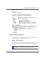
Example: If the command syntax is:
ping <ip_address>, you enter:
ping 192.32.10.12
bold courier text
Indicates text that you need to enter and command
names and options.
Example: Enter ipconfig /release.
Example: Use the winipcfg command.
313371-A
Preface
italic text
27
Indicates file and directory names, new terms, book
titles, and variables in command syntax descriptions.
Where a variable is two or more words, the words are
connected by an underscore.
Example: If the command syntax is:
dns <name_server>
<name_server> is one variable and you substitute one
value for it.
screen text
Indicates command syntex and system output, for
example, prompts and system messages.
Example: Waiting for Contivity to restart.
separator ( > )
Shows menu paths.
Example: From the Window Start menu, choose
Settings > Control Panel.
Related publications
For more information about using Contivity Branch Access, refer to the following
publications:
•
Important Notice for the Contivity Branch Access Software Version 7.20
(part number 313368-A)
Provides instructions for viewing documentation and installing the Contivity
Branch Access management software and third-party applications (Adobe*
Acrobat Reader*, Netscape Communicator*, and AniTa Terminal Emulator*).
•
Installing the Contivity Branch Access Management Software Version 7.20
(part number 313367-A)
Provides instructions for installing the Contivity Branch Access management
software.
•
Setting Up the Contivity 100 Unit (part number 313369-A)
Provides instructions on installing and administering the Contivity 100 unit
hardware.
Using the Contivity Branch Access Management Software Version 7.20
28
Preface
•
Setting Up the Contivity 400 Unit (part number 313370-A)
Provides instructions on installing and administering the Contivity 400 unit
hardware.
•
Using the Contivity Branch Access Management Software Version 7.20
(part number 313371-A)
Provides an introduction to the Contivity Branch Access management
software, instructions for administering the product, and procedures for using
Contivity features.
•
Reference for the Contivity Branch Access Command Line Interface Version
7.20 (part number 313372-A)
Provides instructions and CLI commands for remotely accessing the
Contivity unit and for administering the unit using out-of-band management.
•
Contivity Branch Access Software and Documentation Version 7.20 CD
(part number 313374-A)
Provides manuals for using and installing the Contivity Branch Access
management software and third-party applications. The CD contains the
following documents:
— Installing the Contivity Branch Access Management Software Version
7.20
— Setting Up the Contivity 100 Unit
— Setting Up the Contivity 400 Unit
— Using the Contivity Branch Access Management Software Version 7.20
— Reference for the Contivity Branch Access Command Line Interface
Version 7.20
You can print selected technical manuals and release notes free, directly from the
Internet. Go to the www.nortelnetworks.com/documentation URL. Find the
product for which you need documentation. Then locate the specific category and
model or version for your hardware or software product. Use Adobe Acrobat
Reader to open the manuals and release notes, search for the sections you need,
and print them on most standard printers. Go to Adobe Systems at the
www.adobe.com URL to download a free copy of the Adobe Acrobat Reader.
You can purchase selected documentation sets, CDs, and technical publications
through the Internet at the www1.fatbrain.com/documentation/nortel URL.
313371-A
Preface
29
How to get help
If you purchased a service contract for your Nortel Networks product from a
distributor or authorized reseller, contact the technical support staff for that
distributor or reseller for assistance.
If you purchased a Nortel Networks service program, contact one of the following
Nortel Networks Technical Solutions Centers:
Technical Solutions Center
Telephone
EMEA
(33) (4) 92-966-968
North America
(800) 4NORTEL or (800) 466-7835
Asia Pacific
(61) (2) 9927-8800
China
(800) 810-5000
An Express Routing Code (ERC) is available for many Nortel Networks products
and services. When you use an ERC, your call is routed to a technical support
person who specializes in supporting that product or service. To locate an ERC for
your product or service, go to the www.nortelnetworks.com/servsup URL. Click
the Tools menu item and then click Express Routing Codes under the Other
heading.
Using the Contivity Branch Access Management Software Version 7.20
30
Preface
313371-A
31
Chapter 1
Introduction
This chapter provides information about the types of network environments in
which the Contivity unit works as well as the services that the Contivity Branch
Access management software provides for your network.
Flexible Business Solution
Contivity Branch Access provides small- and medium-size businesses and
business branches with secure and managed Internet access as well as an
extensive set of services that matches the needs of today’s business activity.
This flexible hardware and software solution simplifies Internet access while
significantly lowering costs, and providing higher reliability and easier
manageability of networked users.
Contivity Branch Access contains multiple Ethernet* interfaces for single or
redundant external broadband (cable and xDSL) modems as well as single- and
dual-analog modems, ISDN connections, and even T1 or E1 connections with
CSU/DSU. Any combination of interfaces can serve as primary or automatically
switched backup redundant links for 100% uptime service for critical business
needs.
Contivity Branch Access also allows for the transparent use of an external Web
caching server. Normally, external Web caching servers require that each
workstation to either be configured for proxy mode or be installed along with an
external switching device to make the caching server access transparent. Contivity
Branch Access functions as a Layer 4 (L4) switch to transparently accommodate
an external Web caching device.
Using the Contivity Branch Access Management Software Version 7.20
32
Chapter 1 Introduction
Figure 1 provides an example of how you can connect your Contivity unit in your
network.
Figure 1 Connecting the Contivity unit in a network
115 / 230
50 / 60 Hz V ~
, 4A / 2A
Link
230VAC
115VAC
Act
Ethernet
10/100
Aux
Configure
Cable/DSL
Modem
ISP
10231EA
Advanced routing
Advanced routing features can create multiple subnets per interface and integrate
smoothly with the Layer 2 (L2) switch to:
•
•
•
•
Add more demilitarized zone (DMZ)-type functions to the existing DMZ
Ethernet interface through the 10/100 seven-port Ethernet switch.
Integrate with Routing Information Protocol (RIP) and RIP2.
Update the system time with Network Time Protocol (NTP) services.
Provide Dynamic Host Configuration Protocol (DHCP) services through
internal DHCP servers as well as via DHCP relay to central office DHCP
servers, Domain Name Service (DNS) proxy caching, and many others.
High-performance throughput
As a high-performance solution, Contivity Branch Access keeps up with any
proposed broadband and routing requirement with an excess of a 200 Mb/s,
full-duplex routing throughput capable of saturating Fast Ethernet links which are
provided by all Ethernet ports on the unit. Virtual private network (VPN)
313367-A
Chapter 1 Introduction
33
throughput approaches Ethernet wire speeds with the Contivity 100 unit and
substantially exceeds that throughput with the Contivity 400 unit—even while
operating Triple Data Encryption Standard (3DES) encryption and either Secure
Hash Algorithm (SHA) or Message Digest 5 (MD5) authentication. VPN tunnels
through broadband could saturate any existing and proposed links even with full
encryption.
How the Contivity unit can function in your network
Before you install the Contivity unit, you should understand your network
environment and how the unit functions in the network.
The Contivity unit can function in your network in three ways. It can:
•
•
•
Provide security – You can isolate your network from the Internet to help
ensure network security. You do this for three reasons:
— To prevent Internet users outside your organization from seeing internal
IP addresses.
— To protect your network from being accessed by intruders or hackers.
— To permit remote LANs to communicate with your LAN over a virtual
private network (VPN) using IP security (IPsec).
Control Internet access – You can restrict your users’ access by date and
time, and you can restrict access to certain sites or newsgroups.
Ease administration – The Contivity Branch Access management software
allows you to adopt existing users and groups from your directory services.
IP networks
For security purposes, on an IP network, you may want to isolate your network
from the Internet. You can do this by configuring the network workstations to pass
through a router before accessing the Internet. However, using a router to isolate
the LAN can be time-consuming to set up and maintain because each LAN user
must have a “legal” IP address and be protected from hackers. Contivity Branch
Access, on the other hand, makes it easy to isolate your IP network from the
Internet by using address translation to translate “illegal” (reserved private) LAN
workstation IP addresses into legal IP addresses.
Using the Contivity Branch Access Management Software Version 7.20
34
Chapter 1 Introduction
On IP networks with IP workstations, there is essentially no limit to the number of
application sessions (instances) that can access the Contivity unit.
Virtual private networks
You can use IP security (IPsec) to create a virtual private network (VPN). A VPN
is a special type of connection that permits remote users or LANs to communicate
with another user or LAN over a public network, such as the Internet. When you
set up a VPN, you are essentially using a public network as your own private,
secure network.
Contivity Branch Access includes a portfolio of VPN options that accept highly
variable ISP environments at branch offices while maintaining critical service
levels for real business needs. You can install and configure a VPN branch
anywhere Internet access is available, through any network or ISP connectivity,
with dynamic or fixed IP addressed accounts, and with any alternative
connectivity.
IPX networks
An IPX network is automatically secure because there is no IP traffic on the
network. In this type of network, the Contivity Branch Access management
software provides quick and easy access to the Internet. For IPX networks with
IPX workstations, Contivity Branch Access supports up to 250 application
sessions.This means that IPX workstations can access the Contivity unit using up
to 250 application instances.
313367-A
Chapter 1 Introduction
35
Services Contivity Branch Access provides
Table 1 describes the services that Contivity Branch Access provides for IP
networks.
Table 1 Services Contivity Branch Access provides
Service
Features
Address
Translation
The address translation service enables the Contivity unit to act like a standard router by
routing IP information from one location to another. This service enables the Contivity unit
to go beyond the simple routing role by translating illegal (reserved private) LAN
workstation IP addresses into legal IP addresses.
Address translation supports the IPsec Encapsulating Security Payload (ESP) protocol.
Alarms
System log (SYSLOG) messages and Simple Mail Transfer Protocol (SNMP) traps
broadcast alarms to third-party daemons for real-time system updates.
Client Login
Contivity Branch Access provides for user identification with your existing LAN directory to
annotate logging and establish access control policies. Contivity Branch Access also
provides graphic views of branch throughputs both for Internet access and VPN tunnels.
DHCP Server
Using the Contivity unit as a DHCP server allows you to configure a single option on each
workstation, and then configure the Contivity unit once.
When you install the Contivity Branch Access management software, the Install program
determines whether or not you are running DHCP on your network. If not, the software
configures itself as a DHCP server. If the software does not configure itself as a DHCP
server and you want to use this service, you must enable it.
DNS Proxy
Server
The Contivity unit acts as a Domain Name Service (DNS) proxy server by translating host
names into numerical IP addresses.
IP Routing
The Contivity unit provides access to the Internet through IP routing. It maintains routing
tables that help it determine the destination of data packets. This enables non-Windows*
workstations (Macintosh*, UNIX*, and OS/2*) to access the Internet through the Contivity
unit as IP workstations.
Remote
Configuration
You can use a Telnet application and CLI commands to configure the Contivity unit from a
remote location. Additionally, you can use a terminal emulation application with the CLI
commands to configure the unit (out-of-band management). Remote configuration also
supports remote recovery, which limits on-site visits by technical support personnel. For
details, refer to Reference for the Contivity Branch Access Command Line Interface
Version 7.20.
SOCKS Proxy
Server
You can configure the Contivity unit as a SOCKS proxy server to handle TCP traffic for
SOCKS clients. If you have IP workstations already configured as SOCKS workstations,
you can use the unit to connect them to the Internet. For details, refer to “Configuring a
Contivity unit as a SOCKS proxy server” on page 186.
Using the Contivity Branch Access Management Software Version 7.20
36
Chapter 1 Introduction
Table 1 Services Contivity Branch Access provides (continued)
Service
Features
VPN Tunnel
You can configure IP security (IPsec) to establish a virtual private network (VPN) tunnel
between a Contivity unit and a Contivity VPN Switch (CVS), between a Contivity unit and
a BayRS, or between two Contivity units. For details, refer to Chapter 2, “IP security and
VPN .”
Web
Configuration
This feature allows you to access and edit the Contivity Branch Access configuration files
using a Web browser. For details, refer to “Changing a unit’s system files” on page 194.
Web (HTTP)
Proxy Server
Enabling the Contivity unit as a Web (HTTP) proxy server provides:
• A single point of contact for LAN workstations
• A single point for LAN workstations to obtain access to other proxies
• Web caching to the network in addition to individual workstations
Deciding what to do next
Contivity Branch Access is a powerful system that enables you to customize
settings and services specifically for your organization. Following are some
suggestions for getting started:
•
•
•
•
•
•
•
313367-A
To use the Contivity unit in a virtual private network (VPN), refer to
Chapter 2, “IP security and VPN,” on page 37.
To establish and maintain control over the Internet sites your users and groups
of users access, for example, block access to Web sites, newsgroups, and
incoming ports, refer to Chapter 3, “User access administration,” on page 79.
To log and view the Internet sites your users are accessing, refer to Chapter 4,
“Internet activity logging,” on page 141.
To configure alarms for system log (SYSLOG) and SNMP trap events, refer
to Chapter 4, “Internet activity logging,” on page 141.
To use the Contivity unit as a Web, DNS, or SOCKS proxy server, refer to
Chapter 5, “Proxy services,” on page 179.
To adjust the default IP services or configure the IP services, refer to
Chapter 6, “Advanced IP configuration,” on page 193.
To speed up the Internet response time even more by caching sites that are
accessed on a regular basis, refer to Chapter 7, “Web cache configuration,” on
page 237.
37
Chapter 2
IP security and VPN
This chapter explains how to configure IP security (IPsec) to configure a virtual
private network (VPN) between a Contivity Branch Access unit and a Contivity
VPN Switch (CVS) or between two Contivity Branch Access units.
Understanding virtual private networking
Contivity Branch Access includes IP security (IPsec) virtual private networking
(VPN) capabilities designed to establish a tunnel with a Contivity VPN Switch
(CVS), another Contivity Branch Access unit at a different location, or other
IPsec-compliant devices.
A VPN is a special type of connection that permits remote users or LANs to
communicate with another LAN over a public network, such as the Internet.
When you set up a VPN, you are essentially using a public network as your own
private, secure network. When users connect through the VPN, you incur only the
local toll charges to your ISP.
To create a VPN, a special connection, called a “tunnel,” is first established
between the two sites. Tunnels allow private IP traffic to flow across the Internet,
including NetBIOS information (for Windows networking) encapsulated within
IP packets. Through the tunnel, all IP-based resources and applications on the
remote LAN become available to the local site.
Using the Contivity Branch Access Management Software Version 7.20
38
Chapter 2 IP security and VPN
User data sessions through tunnels can specify DES encryption to assure privacy,
authentication (which proves that the data was not intercepted and modified), or
both. Contivity Branch Access supports 56-bit encryption (DES) for VPN
tunneling as a standard feature. Contivity Branch Access also supports 168-bit
encryption (3DES) as an add-on feature.
Note: The export of 3DES encryption outside North America is
regulated by the U.S. Government. If you require 3DES encryption, you
must purchase the 3DES Encryption Module (part number DM0010001).
Contact your Nortel Networks sales representative for more information.
For authentication, Contivity Branch Access supports:
•
•
MD5 – Message Digest 5
SHA – Secure Hash Algorithm
Understanding modes
When you configure a tunnel between two Contivity Branch Access units or a
Contivity Branch Access unit and a CVS, the Setup program determines what
mode needs to be used. After you add a VPN, you can change the mode to be used
in the tunnel.
Internet Security Association and Key Management Protocol (ISAKMP)
negotiations proceed in two phases. During phase 1, two ISAKMP peers establish
a secure, authenticated channel with which to communicate. The ISAKMP is used
to protect further negotiation traffic. During phase 2, other Security Associations
(SA) are negotiated on behalf of IPsec.
The key is the password for the tunnel and must be mutually agreed upon by both
ends. Internet Key Exchange (IKE) defines two basic methods used to accomplish
a phase 1 authenticated key exchange:
•
313371-A
Main mode – A main-mode connection provides identity protection because
the identity of the endpoints (peers) is exchanged in encrypted messages after
the Diffie-Hellman key exchange. The IP address is used for identification.
Chapter 2 IP security and VPN
•
39
Aggressive mode – In an aggressive-mode connection, the name of the tunnel
interface is sent as the source ID in the initial proposal. This allows the remote
gateway to identify the incoming connection by name, rather than by IP
address and can, therefore, be used with dynamic IP addresses.
The CVS software has implemented aggressive mode for non-Contivity
clients to support more client implementations. Contivity Branch Access
leverages this capability to act as a single-user client on behalf of the network
(many-to-one NAT).
Using perfect forward secrecy (PFS)
Perfect forward secrecy (PFS) means that the compromise of a single key permits
access only to data protected by that key.
The PFS setting between the Contivity Branch Access unit and the CVS must
match. The Contivity Branch Access unit responds to a phase 2 key exchange
performed by the destination regardless of this setting. Note that PFS also incurs
significant additional computational overhead that you may want to avoid unless
you understand the security implications and PFS is required.
The default setting for PFS depends on whether you add an IPsec tunnel for
another Contivity Branch Access unit or for a CVS. When connecting to another
Contivity Branch Access unit, the default is off; when connecting to a CVS, the
default is on.
To enable PFS:
1
Start Setup, and if prompted, select a unit to configure.
2
In the Interfaces area, select the IPsec interface for which you want to modify
the PFS.
3
Click Configure.
The IPsec Configuration dialog box opens (Figure 2).
Using the Contivity Branch Access Management Software Version 7.20
40
Chapter 2 IP security and VPN
Figure 2 IPsec Configuration dialog box
4
Select the PFS check box to enable perfect forward secrecy.
•
5
To disable PFS, clear the check box.
Click OK.
Using the default network specification
Contivity Branch Access has an IPsec form of “default network.” This default
network is used to select the Contivity Branch Access unit’s source address for a
packet whose destination is at the other end of an IPsec tunnel. This feature allows
Contivity Branch Access to participate in its own IPsec tunnels for its own
services such as DNS and proxies. You can also combine the default network
command with NAT so that all addresses can be translated to a single source
address that is also a valid source address in an IPsec tunnel.
313371-A
Chapter 2 IP security and VPN
41
To modify your default network setting:
1
Start Setup, and if prompted, select a unit to configure.
2
Select the IPsec interface for which you want to modify the default network
setting.
3
Click Configure.
The IPsec Configuration dialog box opens (Figure 2 on page 40).
4
In the Default Network area, select an interface from the list.
5
Click OK.
Managing local and remote IP addresses
You can add or remove local and remote IP addresses for a VPN tunnel. Adding a
remote address of 0.0.0.0/0 designates non-split tunneling while specifying the
actual remote subnet designates split tunneling.
•
Non-split tunneling – When you configure a VPN with non-split tunneling,
Contivity Branch Access sends all packets over the IPsec tunnel.
•
Split tunneling – When you configure a VPN with split tunneling, Contivity
Branch Access sends the packets destined for the Internet outside of the IPsec
tunnel and directly to the Internet, and sends only the packets destined for the
VPN over the IPsec tunnel. The benefit of a split-tunnel configuration is that
each site’s Internet traffic does not traverse the IPsec tunnel, and the home
office does not have to provide Internet connectivity for all of the branch
offices.
Adding a local or remote IP address
To add a local or remote IP address:
1
In the IPsec Configuration dialog box, in the Local Addresses or Remote
Addresses area, click Add.
The Enter IP Address dialog box opens (Figure 3).
Using the Contivity Branch Access Management Software Version 7.20
42
Chapter 2 IP security and VPN
Figure 3 Enter IP Address dialog box
2
In the Address box, enter the IP Address of a local or remote network that is to
be allowed to participate in the tunnel.
3
In the Bits box, enter the number of bits.
4
Click OK.
Removing a local or remote IP address
To remove a local or remote IP address:
1
In the IPsec Configuration dialog box, in the Local Addresses or Remote
Addresses area, select the address and then click Remove.
2
In the confirmation dialog box, click Yes.
Using pings
Contivity Branch Access provides a background ping facility that you can use to
control or monitor the connection state of a VPN and serve as a “keep-alive” for
the tunnel.
There are two types of pings:
•
•
313371-A
Control – Use a control ping when you want to maintain a permanent tunnel
connection.
Monitor – Use a monitor ping when you do not want to keep the connection
active but you still want to check the status of a tunnel. This type of ping is
typically used with a dial-up connection.
Chapter 2 IP security and VPN
43
The following capabilities are available for a ping:
•
All modes – For all modes of ping, you can specify the destination address,
packet length, interval, and timeout. The destination should be some device
that is reachable and for which a response is representative of the desired
connectivity.
For example, if the purpose of the ping is to validate a VPN connection, then
it is best to choose a destination that is reached through the VPN tunnel, such
as the private address of the remote Contivity Branch Access unit or the CVS.
•
Monitor mode – The monitor mode does not initiate a connection and is not
considered to be activity against a dial-up interface’s idle timeout. This mode
does not keep a connection active.
Note: A monitor ping is considered to be activity on the CVS but is not
considered to be activity against the Contivity Branch Access unit’s
dial-up timeout; therefore, Contivity Branch Access is free to drop the
line. After the line is dropped, the monitor ping disables the connection.
The CVS’s idle timeout disables the other end of the connection.
In monitor mode, if the specified interface is not active the ping does not
occur. Also, in the case of an IPsec interface, if the interface used to reach the
corresponding remote gateway is not active, the ping does not occur. If an
IPsec interface is specified and no response is received for three consecutive
pings, the tunnel is dropped and is re-established as required by normal VPN
activity.
If the ping fails for three consecutive times, the interface is brought down, but
is not disabled from further activity. This is normally used for IPsec interfaces
because the ping failure indicates that the IPsec tunnel is no longer operating
properly. If this happens, any active IPsec tunnels are dropped and are
re-established as required by normal activity.
•
Control mode – The control mode is useful for maintaining permanent
connections, switching to a backup interface when a primary interface
becomes unavailable and the primary interface does not have a reliable
indication of its availability, or both.
Using the Contivity Branch Access Management Software Version 7.20
44
Chapter 2 IP security and VPN
For example, in xDSL and cable modem environments, the Contivity Branch
Access interface that connects to the Internet is usually an Ethernet interface,
and that interface is always active as long as the link exists between Contivity
Branch Access and the xDSL or cable modem. A ping in control mode always
attempts to use the specified interface (even if it is considered inactive for
normal use), and if three consecutive responses are not received, the interface
is made inactive (if an IPsec interface is used, any associated tunnels are
dropped). The ping continues to transmit on the interface, even while it is
unavailable for normal traffic. After a response is received, the interface is
made available again.
Note: The control mode initiates a connection and is considered to be
activity. A control mode ping attempts to keep the path to the destination
active at all times.
•
Background mode – Background mode is a standard ping with no other
special provisions. This mode sends a ping to the specified destination, which
initiates a connection if required, and is considered to be activity. The receipt
of a response (or the lack of one) has no effect on system operation.
To configure a ping:
1
Start Setup, and if prompted, select a unit to configure.
2
Choose Support > Ping’s.
The Pings dialog box opens (Figure 4).
313371-A
Chapter 2 IP security and VPN
45
Figure 4 Pings dialog box
3
Click Add.
The Ping Configuration dialog box opens (Figure 5).
Using the Contivity Branch Access Management Software Version 7.20
46
Chapter 2 IP security and VPN
Figure 5 Ping Configuration dialog box
4
Enter the following information:
•
313371-A
IP address / host – Enter the IP address or host name of the remote end
you want to ping. When using ping from Contivity Branch Access unit to
Contivity Branch Access unit, it is best to select the private address of the
remote Contivity Branch Access unit to ping. When using ping from a
Contivity Branch Access unit to a CVS, it is best to select the private
address of the CVS to ping.
— Length – Enter the length of the data packet. This box is normally left
blank so that the shortest possible packet is used.
— Interval – Enter the number of seconds between ping attempts. The
default is 1 second.
— Timeout – Enter the number of seconds to wait for a ping response.
The default is 5 seconds.
Chapter 2 IP security and VPN
5
47
Select the type of ping to run:
•
•
•
Monitor – Used for IPsec, a monitor ping checks the validity of a tunnel.
After a series of failed pings, this option ends the tunnel. This type of ping
does not initiate a dial-up connection or cause a dial-up connection to be
kept active. The ping monitors the validity of the tunnel.
Control – A control ping manages the operating status of an interface.
This type of ping can be used to force a connection to be kept active at all
times.
Background – Runs the ping in the background. A background ping can
be used to keep a dial-up connection active.
6
If you selected Monitor or Control, select the interface to monitor or control
from the Interface list; otherwise skip this step.
7
Select the interface used to initiate the ping from the Source list.
The default source is the IP address of the interface that is closest to the
destination.
8
Click OK to close the Ping configuration dialog box.
9
Click OK to close the Pings dialog box.
10 In the Setup main window, click Save and Exit.
Understanding how a Contivity unit-to-Contivity unit VPN
works
The Contivity Branch Access unit’s VPN capabilities are designed to establish a
secure tunnel with another Contivity Branch Access unit at a different location.
When you establish a VPN between two Contivity Branch Access units, you can
decide what types of connection you want to allow to the unit. This option
provides you with another means for selecting the level of security necessary.
You can specify whether you want to allow only incoming or outgoing
connections to establish a tunnel. You can also specify whether to allow both
incoming and outgoing connections to establish a tunnel.
Using the Contivity Branch Access Management Software Version 7.20
48
Chapter 2 IP security and VPN
Allowing only incoming connections
When connecting with a remote site that has a dynamic IP address or is a
third-party IPsec client, configure Contivity Branch Access to allow only
incoming connections.
To allow only incoming connections to establish a tunnel:
1
Start Setup, and if prompted, select a unit to configure.
2
In the main Setup dialog box, click Add.
The Select Connection Type dialog box opens (Figure 6).
Figure 6 Select Connection Type dialog box
3
Click IPsec.
The Select Connection Device dialog box opens (Figure 7).
Figure 7 Select Connection Device dialog box
313371-A
Chapter 2 IP security and VPN
4
49
Click Instant Internet.
The Select Type of Connections dialog box opens (Figure 8).
Figure 8 Select Type of Connections dialog box
5
Click Responder.
The IPsec Configuration dialog box opens (Figure 9).
Figure 9 IPsec Configuration dialog box
6
In the Name box, enter a name for the tunnel.
This name must match the one used on the other end of the tunnel.
Using the Contivity Branch Access Management Software Version 7.20
50
Chapter 2 IP security and VPN
7
In the Key box, enter a key for the tunnel.
The key is the password for the tunnel and must be mutually agreed upon by
both Contivity Branch Access units. A key cannot begin with a backslash (\).
The Local Addresses area displays the IP addresses of local networks that are
permitted to participate in the tunnel. The default local address, 0.0.0.0/0,
allows all IP addresses on your LAN to be reached through the tunnel;
however, this provides no security in terms of the peer’s selection of local
networks.
•
To specify the addresses allowed in the tunnel, click Add. For more
information, refer to “Adding a local or remote IP address” on page 41.
8
When you are finished entering information, click OK.
9
In the main Setup window, click Save and Exit.
Allowing only outgoing connections
Configure Contivity Branch Access to allow only outgoing connections when a
Contivity Branch Access unit is initiating a connection but is not receiving
incoming connections, such as when the unit has a dynamic IP address.
To allow only outgoing connections to establish a tunnel:
1
Start Setup, and if prompted, select a unit to configure.
2
Click Add.
3
In the Select Connection Type dialog box (Figure 6 on page 48), click IPsec.
4
In the Select Connection Device dialog box (Figure 7 on page 48), click
Instant Internet.
5
In the Select Type of Connections dialog box (Figure 8 on page 49), click
Initiator.
The IPsec Configuration dialog box opens (Figure 10).
313371-A
Chapter 2 IP security and VPN
51
Figure 10 IPsec Configuration dialog box
6
Enter the following information:
•
•
•
7
Name – Enter a name for the tunnel. This name must match the one used
on the other end of the tunnel.
Key – Enter a key for the tunnel. The key is the password for the tunnel
and must be mutually agreed upon by both Contivity Branch Access
units. A key cannot begin with a backslash (\).
Destination – Enter the remote Contivity Branch Access unit’s public
address or fully qualified domain name (FQDN). If you specify an
FQDN, it is resolved each time a connection is initiated.
In the Local Addresses area, click Add to enter the IP addresses of a local
network allowed to participate in the tunnel. For more information, refer to
“Managing local and remote IP addresses” on page 41.
The default local address is that of your LAN.
8
In the Remote Addresses area, click Add to enter the IP addresses of the
remote site that is accessed through the tunnel. For details, refer to “Adding a
local or remote IP address” on page 41.
9
Click OK.
The Monitor Connection dialog box opens (Figure 11).
Using the Contivity Branch Access Management Software Version 7.20
52
Chapter 2 IP security and VPN
Figure 11 Monitor Connection dialog box
10 Do one of the following:
•
•
If you do not want to monitor or control the connection, click No. Skip to
step 13.
If you want to monitor or control the connection, click Yes. The Enter
Monitor / Control Connection Information dialog box opens (Figure 12).
Continue with step 11.
Figure 12 Enter Monitor / Control Connection Information dialog box
313371-A
Chapter 2 IP security and VPN
53
11 Enter the following information:
•
•
•
Connection – Choose whether you want to monitor or control the
connection. For more information, refer to “Using pings” on page 42.
IP Address – Enter the IP address of a device that is reachable through
the tunnel and represents the desired connectivity (usually the private
address of the remote unit).
Source – Select the source interface of the connection being monitored or
controlled.
12 Click OK.
13 In the main Setup window, click Save and Exit.
Allowing both outgoing and incoming connections
Configure Contivity Branch Access to allow both incoming and outgoing
connections to establish a tunnel only if your environment does not require high
security.
To allow both incoming and outgoing connections to establish a tunnel:
1
Start Setup, and if prompted, select a unit to configure.
2
Click Add.
3
In the Select Connection Type dialog box (Figure 6 on page 48), click IPsec.
4
In the Select Connection Device dialog box (Figure 7 on page 48), click
Instant Internet.
5
In the Select Type of Connections dialog box (Figure 8 on page 49), click
Peer to Peer.
The IPsec Configuration dialog box opens (Figure 13).
Using the Contivity Branch Access Management Software Version 7.20
54
Chapter 2 IP security and VPN
Figure 13 IPsec Configuration dialog box
6
Enter the following information:
•
•
•
7
Name – Enter a name for the tunnel. This name must match the one used
on the other end of the tunnel.
Key – Enter a key for the tunnel. The key is the password for the tunnel
and must be mutually agreed upon by both Contivity Branch Access
units. A key cannot begin with a backslash (\).
Destination – Enter the remote Contivity Branch Access unit’s public
address or fully qualified domain name (FQDN). If you specify an
FQDN, it is resolved each time a connection is initiated.
In the Local Addresses area, click Add to enter the IP addresses of a local
network allowed to participate in the tunnel. For details, refer to “Managing
local and remote IP addresses” on page 41.
You can specify an address here to force a packet to go through the tunnel.
The default local address is that of your LAN.
8
In the Remote Addresses area, click Add to enter the IP addresses of the
remote site that allowed to participate in the tunnel. For details, refer to
“Adding a local or remote IP address” on page 41.
9
Click OK.
The Monitor Connection dialog box opens (Figure 14).
313371-A
Chapter 2 IP security and VPN
55
Figure 14 Monitor Connection dialog box
10 Do one of the following:
•
•
If you do not want to monitor or control the connection, click No. Skip to
step 13.
If you want to monitor or control the connection, click Yes. The Enter
Monitor / Control Connection Information dialog box opens (Figure 15).
Continue with step 11.
Figure 15 Enter Monitor / Control Connection Information dialog box
Using the Contivity Branch Access Management Software Version 7.20
56
Chapter 2 IP security and VPN
11 Enter the following information:
•
•
•
Connection – Choose whether you want to monitor or control the
connection. For more information, refer to “Using pings” on page 42.
IP Address – Enter the IP address of a device that is reachable through
the tunnel and represents the desired connectivity (usually the private
address of the remote unit).
Source – Select the source interface of the connection being monitored or
controlled.
12 Click OK.
13 In the main Setup window, click Save and Exit.
Understanding how a Contivity Branch Access unit-to-CVS
VPN works
The Contivity Branch Access unit’s VPN capabilities are designed to establish a
tunnel with a Contivity VPN Switch (CVS) at another location. You can configure
a Contivity Branch Access unit-to-CVS VPN regardless of whether your unit
receives a static IP address or a dynamic IP address from your ISP. The type of
connection that should be configured depends on the type of IP address the unit
receives:
•
•
313371-A
Dynamic IP address – When your Contivity Branch Access unit receives a
dynamic IP address from your ISP, the tunnel uses aggressive mode. When a
unit that uses dynamic IP addresses establishes a tunnel with a CVS, the CVS
considers the Contivity Branch Access unit to be a “non-Contivity client,” or,
with CVS version 4.0 or later, branch office connections are supported in
aggressive mode.
Static IP address – When your Contivity Branch Access unit receives a static
IP address from your ISP, the tunnel uses main mode. If a unit that uses static
IP addresses establishes a tunnel with a CVS, the CVS regards the Contivity
Branch Access unit as a branch office. This type of tunneling is called
branch-to-branch tunneling.
Chapter 2 IP security and VPN
57
VPN configuration guidelines
Contivity Branch Access supports both the CVS branch-to-branch office mode
and non-Contivity client modes. Following are some general guidelines to keep in
mind before you begin configuring a VPN.
Branch-to-branch mode
If you are using CVS software earlier than version 4.0, at least one public, static
IP address must be available at both the location of the CVS and of the Contivity
Branch Access unit. A static IP address is not required for CVS software version
4.0 or later.
Note: Only the CVS branch office routing type of “static” is supported;
RIP mode works only between CVSs.
Client mode
•
•
•
•
Because all traffic must be translated to the static address that was assigned to
the Contivity Branch Access unit, the static address must exist on the
Contivity Branch Access unit. Often, the static address is the same as the
Contivity Branch Access unit’s private LAN address. If the address is not the
same, create an alias interface for the Contivity Branch Access unit and assign
the static address to that alias. For more information on aliases, refer to
“Configuring an alias for an interface” on page 230.
Set the default network to the interface that has the static address, and enable
output NAT on the IPsec interface. This translates all packets leaving the
IPsec interface (before they are encrypted and encapsulated) to have that
interface’s address as a source. Alternatively, you can configure input NAT on
the private LAN interface.
Another router bordering the CVS must provide a route to the Contivity
Branch Access unit’s public address. You can use proxy ARP if the Contivity
Branch Access unit’s default network address is valid on the CVS private
network.
There are no restrictions on the connection medium used by the Contivity
Branch Access unit. The unit supports IPsec on any type of available
interface, including a LAN connection to another router.
Using the Contivity Branch Access Management Software Version 7.20
58
Chapter 2 IP security and VPN
•
•
Contivity Branch Access does not support certificates for authentication; only
pre-shared keys are used. The name of the IPsec interface created for the
Contivity Branch Access unit must match the user ID that was created for the
CVS.
When you use Setup to configure a connection to the CVS, perfect forward
secrecy (PFS) is enabled on the Contivity Branch Access unit by default.
PFS incurs significant additional computational overhead that you may
want to avoid unless you understand the security implications and PFS is
absolutely required.
•
•
•
Contivity Branch Access does not support 40-bit Data Encryption Standard
(DES). Contivity Branch Access does support 56-bit encryption (DES) for
VPN tunneling as a standard feature, and supports 168-bit encryption (3DES)
as an add-on feature.
During phase 1 negotiations, the CVS requires single DES. If you want to use
3DES, you must also select single DES for encryption type. Contivity Branch
Access uses 3DES for the actual tunneled data if it is configured as higher
priority than DES.
Contivity Branch Access does not support compression; however this does
not affect compression on the CVS. You can enable compression on the CVS.
DNS proxy server
If you enable the Contivity Branch Access unit as a DNS proxy server, the DNS
addresses configured in Contivity Branch Access must be able to resolve all
desired host names, whether part of the public Internet, the private network, or
otherwise.
As an alternative, if you configure Contivity Branch Access clients to use a DNS
proxy server other than the Contivity Branch Access unit, they follow the rules for
Microsoft* networking, which allows more flexibility in determining name
resolution. For more information, refer to your Microsoft networking
documentation.
313371-A
Chapter 2 IP security and VPN
59
How a tunnel is initiated
Neither the Contivity Branch Access unit nor the Contivity VPN Switch (CVS)
can manually initiate a branch office connection. To initiate a VPN tunnel, some
activity must be performed, such as using a ping or browsing to a site that uses the
tunnel. For example, a host on one LAN could ping a host on another LAN where
the packet is expected to travel through a configured VPN tunnel.
Tunnel validity
The IPsec protocol does not provide a “keep-alive” mechanism as part of its
standard. If one endpoint of a tunnel disconnects without the knowledge of the
other (for example, if the server on one end is rebooted), the remaining “live”
endpoint still attempts to send traffic through the tunnel. In this situation, the
tunnel status may appear to be valid to the live endpoint, but communications are
not possible. However, after the disconnected endpoint (the end that was
rebooted) initiates a new tunnel as warranted by traffic, the tunnel is reestablished
and operates properly.
Contivity Branch Access provides a ping utility as a “keep-alive” mechanism in
order to circumvent the problems associated with losing one end of a tunnel. For
more information refer to “Using pings” on page 42.
Dial-up environments and tunnel validity
In a dial-up or equivalent (analog, ISDN, PPPoE) environment, the Internet
connection may not exist at all times which can cause a problem when a tunnel is
no longer valid. A tunnel connection is completely independent of the dial-up
connection to the Internet and remains valid and expires as configured regardless
of whether the dial-up connection is active. When static IP addressing is used for a
VPN, this is of little consequence because as soon as the connection is
reestablished, the tunnel traffic can continue. When the Contivity Branch Access
unit’s Internet connection is re-established, if the public IP address assigned by
the ISP differs from the previous one used to establish the tunnel, Contivity
Branch Access deletes the tunnel immediately. Further traffic (or a control ping)
re-establishes the tunnel.
Using the Contivity Branch Access Management Software Version 7.20
60
Chapter 2 IP security and VPN
If, however, the dial-up connection is interrupted (inadvertently or intentionally
due to an idle timeout), and the gateway at one endpoint of the tunnel informs the
other endpoint that the tunnel is to be deleted, this information cannot reach the
remote gateway and it will not know that the tunnel is no longer valid. After the
dial-up connection is re-established, it continues to attempt to use this now invalid
tunnel (as described above regarding one endpoint disconnecting). This situation
occurs due to a limitation of the IPsec protocol; however, there are three ways you
can work around this limitation:
•
•
Maintain traffic over the tunnel in both directions on a relatively constant
basis. This option is possible only when the dial-up connection can exist at all
times. One way to maintain traffic is to send a ping command back and forth
from one gateway’s network to the other.
Reduce the VPN connection timeout. By using shorter timeouts, you can
determine the maximum amount of time required for the system to recover.
Before you implement this solution, consider that substantial computational
overhead is required.
Note: The phase 1 negotiation timeout is controlled on the CVS with the
Forced Logoff parameter, whereas a subnet tunnel is controlled by the
re-key timeout.
•
Use a ping to monitor or control the tunnel (refer to “Using pings” on
page 42).
Tunnel timeouts
The Contivity Branch Access unit’s IPsec feature performs all communications
across a Security Association (SA), also referred to as a tunnel. An SA is
negotiated using Internet Key Exchange (IKE) standards using two main types of
negotiation, phase 1 and phase 2, and a timeout (specified by time or amount of
data) is associated with each SA. When this timeout expires, the SA is no longer
valid and a new one must be negotiated if needed. The phase 1 negotiation uses a
very secure algorithm that establishes secure communications between the
gateways (the Contivity Branch Access unit and the CVS) but does not refer to
any specific tunnel.
313371-A
Chapter 2 IP security and VPN
61
When phase 1 is complete, additional SAs are negotiated using the phase 2
protocol, with the keys exchanged across the secure phase 1 tunnel. These SAs
refer to specific network pairs.
It is important to understand that there is a separate SA for each possible
combination of subnets. For example, if the Contivity Branch Access unit’s IPsec
configuration has two local subnets and four remote subnets, then a total of eight
separate SAs exists if all subnets are communicating with each other. In this case,
the CVS has four subnets listed in the Local Accessible Networks and two subnets
listed in the Remote Accessible Networks for the branch office connection.
Note: When troubleshooting a VPN tunnel, remember that each of these
SAs is established as needed and each is subject to its own possible
success or failure during negotiation.
Either gateway can establish communications. For example, an SA can be
initiated by either the Contivity Branch Access unit or by the CVS. However, the
initiator of an SA determines the timeout for that SA. For example, if the CVS
initiates a tunnel and has a timeout value of 15 and the Contivity Branch Access
unit accepts the tunnel but has a timeout of 18, the timeout value for the tunnel is
15 because the CVS initiated the tunnel.
When the Contivity Branch Access unit initiates a phase 1 connection, it sets the
timeout to be the same as that used for the phase 2 SAs. This approximates the
effect of perfect forward secrecy (PFS) because the phase 1 SA expires after the
specified timeout and must be renegotiated before any phase 2 SAs can be
re-keyed. Note that when the CVS initiates a phase 1 SA, it does not specify a
timeout.
Note: If this behavior is undesirable, use the Forced Logoff parameter in
the CVS to apply the specified timeout to the phase 1 SA. For details,
refer to your CVS documentation.
Using the Contivity Branch Access Management Software Version 7.20
62
Chapter 2 IP security and VPN
Tunneling to a CVS using a branch-to-branch connection
When a tunnel is established between a CVS and a Contivity Branch Access unit
that routes a complete subnet, the tunnel is called a branch-to-branch tunnel. A
CVS earlier than version 4.0 requires that the Contivity Branch Access unit have a
static public IP address. A CVS version 4.0 and later allows a branch-to-branch
connection (in aggressive mode) with a Contivity Branch Access unit that has a
dynamic IP address.
When you configure a branch-to-branch VPN tunnel between a Contivity Branch
Access unit and a CVS, network address translation (NAT) is typically not
performed through the tunnel.
Configuring a VPN between a Contivity Branch Access unit and a CVS is a
two-step process:
•
•
Configure the branch office connection in the CVS, (next).
Configure the Contivity Branch Access unit as a branch office VPN tunnel.
You will configure a main-mode tunnel if a static IP address is used, or an
aggressive-mode tunnel if a dynamic IP address is used (refer to “Configuring
Contivity Branch Access as a branch office VPN tunnel” on page 64).
Example: Configuring a branch office connection on the CVS
This procedure provides an example for configuring a branch office connection on
the CVS for tunneling. For detailed information, refer to your product
documentation.
To configure a branch office connection on the CVS:
1
In the CVS main window, choose Profiles > Networks.
2
Enter a network name and then click Create.
3
In the New Subnet area, do one of the following:
•
•
If you are using split tunneling, specify the IP addresses and masks of all
local subnets that will participate in the VPN.
If you are using non-split tunneling, specify an IP address of 0.0.0.0 and a
mask of 0.0.0.0.
For more information on split and non-split tunneling, refer to “Managing
local and remote IP addresses” on page 41.
313371-A
Chapter 2 IP security and VPN
63
4
Click Add to create the new network.
5
Click Close.
6
In the CVS main window, choose Profiles > Branch Office.
7
Select the user involved in the tunnel and then click Edit.
8
If you are using a CVS version 4.0 or later, in the Connection Type list, do one
of the following:
•
•
9
Select Peer to Peer for a main-mode connection (static IP address).
Select Responder for an aggressive-mode connection (dynamic IP
address).
If you are configuring a main-mode (Peer to Peer) connection, in the
Configuration area, enter the Contivity Branch Access unit’s public IP address
in the Remote Endpoint Address box; otherwise, skip this step.
10 In the Configure Routing areas, click IP.
11 In the Routing area, select the Static option.
12 In the Local Accessible Networks area, select the network you created in
step 2.
13 In the Remote Accessible Networks area, click Add.
14 In the New Subnet Details area, enter the following information and then click
OK.
•
•
IP Address – Enter the Contivity Branch Access unit’s LAN-side IP
address.
Mask – Enter the Contivity Branch Access unit’s LAN-side subnet mask.
15 Click OK.
16 If you are using CVS version 4.0 or later, in the IPsec Authentication area, do
one of the following:
•
•
If you are using a main-mode (Peer to Peer) connection, select a
pre-shared key option (Text or Hex), and then enter and confirm the
pre-shared key.
If you are using an aggressive-mode (Responder) connection, enter an
Initiator ID that will uniquely identify this branch office. Enter a
corresponding pre-shared key option (Text or Hex), and then confirm the
pre-shared key.
Using the Contivity Branch Access Management Software Version 7.20
64
Chapter 2 IP security and VPN
17 Click OK.
Configuring Contivity Branch Access as a branch office VPN tunnel
If your ISP provides you with a static IP address, you must configure a
main-mode connection (Peer to Peer). If your ISP provides you with a dynamic IP
address, you must configure an aggressive-mode connection (Initiator).
To configure Contivity Branch Access as a branch office VPN tunnel:
1
Start Setup, and if prompted, select a unit to configure.
2
In the main Setup window, click Add.
3
The Select Connection Type dialog box opens (Figure 16).
Figure 16 Select Connection Type dialog box
313371-A
4
Click IPsec.
5
The Select Connection Device dialog box opens (Figure 7).
Chapter 2 IP security and VPN
65
Figure 17 Select Connection Device dialog box
6
Click Contivity.
The Select Type of Connection dialog box opens (Figure 18).
Figure 18 Select Type of Connection dialog box
7
Do one of the following:
•
•
To configure a main-mode connection (static IP address), click
Branch - Peer to Peer.
To configure an aggressive-mode connection (dynamic IP address), click
Branch - Initiator.
The IPsec Configuration dialog box opens (Figure 19).
Using the Contivity Branch Access Management Software Version 7.20
66
Chapter 2 IP security and VPN
Figure 19 IPsec Configuration dialog box
8
Enter the following information:
•
•
•
9
Name – Do one of the following:
— For a main-mode connection (Peer to Peer), accept the suggested
default name or enter a unique name for the tunnel. This name should
be one that you can associate easily with this particular tunnel. This
name does not have to match the one used at the other end of the
tunnel.
— For an aggressive-mode connection (Initiator), enter a unique name
for the tunnel. This name must match the initiator ID you configured
for this connection on the CVS.
Key – The key is the password for the tunnel and must match the
pre-shared key you configured on the CVS. A key cannot begin with a
backslash (\).
Destination – Specify the public IP address of the CVS.
In the Local Addresses area, click Add to enter the local IP addresses allowed
to participate in the tunnel. For more information, refer to “Adding a local or
remote IP address” on page 41.
The information in this box should coincide with the network you configured
on the CVS. The default local address is that of your LAN.
10 In the Remote Addresses area, click Add to enter the IP addresses of a remote
site allowed to participate in the tunnel. For more information, refer to
“Adding a local or remote IP address” on page 41.
313371-A
Chapter 2 IP security and VPN
67
11 Click OK.
The Monitor Connection dialog box opens (Figure 20).
Figure 20 Monitor Connection dialog box
12 Do one of the following:
•
•
If you do not want to monitor or control the connection, click No. Skip to
step 15.
If you want to monitor or control the connection, click Yes. The Enter
Monitor / Control Connection Information dialog box opens (Figure 21).
Continue with step 13.
Figure 21 Enter Monitor / Control Connection Information dialog box
Using the Contivity Branch Access Management Software Version 7.20
68
Chapter 2 IP security and VPN
13 Enter the following information:
•
•
•
Connection – Choose whether you want to monitor or control the
connection. For more information, refer to “Using pings” on page 42.
IP Address – Enter the IP address of a device that is reachable through
the tunnel and represents the desired connectivity (usually the private
address of the remote unit).
Source – Select the source interface of the connection being monitored or
controlled.
14 Click OK.
15 In the main Setup window, select the VPN tunnel and then click Configure.
The IPsec Configuration dialog box opens (Figure 22).
Figure 22 IPsec Configuration dialog box
313371-A
Chapter 2 IP security and VPN
69
16 Clear the PFS check box if PFS is disabled on the CVS.
•
NAT is optional. For more information on NAT, refer to “Configuring
NAT” on page 203.
17 In the Default Network area, select your router connection from the list.
18 Click OK.
19 In the main Setup window, click Save and Exit.
The tunnel is configured. For more information on how to initiate a tunnel after it
has been configured, refer to “How a tunnel is initiated” on page 59.
Tunneling to the CVS when the Contivity Branch Access unit
acts as a non-Contivity client
When a tunnel is established between the CVS and a Contivity Branch Access
unit that uses a single IP address through the tunnel, the CVS is configured to
accept the connection from, a non-Contivity client. This type of connection allows
a dynamic IP address from the ISP, and an aggressive-mode tunnel is used. CVS
version 2.6 and later includes support for non-Contivity clients.
Contivity Branch Access can send identification information when a connection is
made using aggressive mode, therefore, the CVS allows the Contivity Branch
Access unit to have a dynamic IP address. However, the CVS never initiates an
aggressive mode connection; all such connections must be initiated from the
opposite end of the tunnel.
Configuring a VPN between a Contivity Branch Access unit and the CVS when
the Contivity Branch Access unit acts as a non-Contivity client is a two-step
process. You will:
•
•
Configure the non-Contivity client connection on the CVS, (next).
Configure the Contivity Branch Access unit as an aggressive-mode VPN
tunnel (refer to “Configuring Contivity Branch Access as a branch office VPN
tunnel” on page 64).
Using the Contivity Branch Access Management Software Version 7.20
70
Chapter 2 IP security and VPN
Example: Configuring a non-Contivity client connection on the CVS
This procedure provides an example for configuring a non-Contivity client
connection on the CVS for tunneling. For detailed information, refer to your
product documentation.
To configure the non-Contivity client connection on the CVS:
1
In the CVS main window, choose Profiles > Networks.
2
Enter a network name and then click Create.
3
In the New Subnet area, do one of the following:
•
•
If you are using split tunneling, specify the IP addresses and masks of all
local subnets that will participate in the VPN.
If you are using non-split tunneling, specify an IP address of 0.0.0.0 and a
mask of 0.0.0.0.
For more information on split and non-split tunneling, refer to “Managing
local and remote IP addresses” on page 41.
4
Click Add to create the new network.
5
Click Close.
6
In the CVS main window, choose Profiles > Groups.
7
Either add a group or select an existing group that will use the VPN and
configure the group with the following information:
a
In the Connectivity area, click Configure. In the Idle Timeout box,
configure the timeout for 1 minute and then click OK.
b
In the IPsec area, click Configure and then do the following:
— In the Split Tunnel Networks box specify the network you created in
step 2.
— In the Client Selection area, configure the CVS to allow
non-Contivity clients for the selected group.
c
8
313371-A
Click OK.
In the CVS main window, choose Profiles > Users
Chapter 2 IP security and VPN
9
71
Either add a user or select an existing user from the group that you configured
in step 7, and configure the user with the following information:
Note: You must configure the user as a local user in the LDAP database
(internal or external); you cannot use RADIUS authentication for this
type of connection.
10 Edit the new or selected user with the following information:
a
In the General area, assign an IP address to the remote user in the Static IP
Address box.
This address must be usable on CVS’s private network, but there are no
restrictions in terms of whether the address is public, private, or even a
native part of CVS’s private network. This address should be the same as
the static address in the Contivity Branch Access setup. Do not add a
subnet mask.
b
In the User Account area, assign a user ID and password in the
appropriate IPsec boxes.
The user ID and password must match the one given on the other end of
the tunnel.
c
Click OK.
11 Ensure that another router on the CVS’s private network has a static route for
the client address with a destination of the CVS’s private address.
You can also use proxy ARP or use the client address redistribution (CAR)
feature on the CVS (version 3.60 or later) to announce the client route to
another router.
Configuring the Contivity Branch Access unit as a non-Contivity
client
To configure the Contivity Branch Access unit as a non-Contivity client:
1
Start Setup, and if prompted, select a unit to configure.
2
In the main Setup window, click Add.
3
In the Select Connection Type dialog box (Figure 16 on page 64), click IPsec.
Using the Contivity Branch Access Management Software Version 7.20
72
Chapter 2 IP security and VPN
4
In the Select Connection Device dialog box (Figure 17 on page 65), click
Contivity.
5
In the Select Type of Connection dialog box (Figure 17 on page 65), click
Client.
The IPsec Configuration dialog box opens (Figure 23).
Figure 23 IPsec Configuration dialog box
6
Enter the following information:
•
•
•
313371-A
Name – Enter a name for the tunnel. This name is the local user you
configured on the CVS.
Key – The key is the password for the tunnel and must match the
pre-shared key you configured on the CVS. A key cannot begin with a
backslash (\).
Destination – Specify the public IP address of the CVS.
Chapter 2 IP security and VPN
7
Select whether the client initiates a tunnel:
•
•
8
73
Using Client Address Redistribution (CAR) – When a client initiates a
tunnel, the CVS assigns an inner address to the client. If the address does
not belong to any of the locally-attached CVS networks, you must enable
CAR to ensure that these addresses are advertised in the dynamic route
updates sent by the CVS.
Static Address – Select the interface that was assigned to the local user
on the CVS. The interface is often the same as the Contivity Branch
Access unit’s private LAN interface. If the address is not the same, Setup
creates an alias interface for the Contivity Branch Access unit and assigns
it a static address.
Click Add to enter the remote IP addresses allowed to participate in the
tunnel.
Note: These addresses must match the addresses of the networks you set
up in the CVS. For more information on adding IP addresses, refer to
“Adding a local or remote IP address” on page 41.
9
Click OK to close the IPsec Configuration dialog box.
The Enter Monitor / Control Connection Information dialog box opens
(Figure 24).
Using the Contivity Branch Access Management Software Version 7.20
74
Chapter 2 IP security and VPN
Figure 24 Enter Monitor / Control Connection Information dialog box
10 Enter the following information:
•
•
•
Connection – Choose whether you want to monitor or control the
connection. For more information, refer to “Using pings” on page 42.
IP Address – Enter the IP address of any device that is reachable through
the tunnel. You might want to use the IP address of the main router at the
home office.
Source – Select the source interface of the connection being monitored or
controlled.
11 Click OK.
12 In the main Setup window, click Save and Exit.
The tunnel is configured. For more information on how to initiate a tunnel after it
has been configured, refer to “How a tunnel is initiated” on page 59.
Note: Setup also creates an alias interface.
313371-A
Chapter 2 IP security and VPN
75
Troubleshooting a VPN tunnel connection
If you have troubles establishing a VPN tunnel connection make sure to check
both ends of the tunnel to make sure that the tunnel configuration matches. Some
common areas that may cause problems include but are not limited to:
•
•
•
PFS settings
Default network settings
IP addresses
Contivity provides several methods for testing and troubleshooting IPsec:
•
•
•
•
•
Use the ipsec CLI command to view a list of active tunnels. For details, refer
to Reference for the Contivity Branch Access Command Line Interface
Version 7.20.
View the Contivity Branch Access unit’s IPsec log to view information about
IPsec negotiations. For details, refer to “Viewing a Contivity unit’s IPsec log”
on page 76.
Use the Monitor program to monitor and control the status of individual
tunnels. The interface list contains the IPsec tunnel names. When you select
an IPsec interface, Monitor displays the status. You can bring the tunnel down
using the line control button on the toolbar. For details on using Monitor, refer
to “Monitor program overview” on page 141.
Use system logging (SYSLOG) to view messages about significant IPsec
system events. For details, refer to “Managing SYSLOG alarms” on
page 165.
Use CVS session statistics to view VPN connection information. For more
information, refer to your Contivity VPN Switch documentation.
You can diagnose most IPsec connectivity problems using a combination of the
Contivity Branch Access IPsec log and the CVS session statistics.
Using the Contivity Branch Access Management Software Version 7.20
76
Chapter 2 IP security and VPN
Viewing a Contivity unit’s IPsec log
The IPsec log details low-level protocol information regarding IPsec negotiations
for a virtual private network (VPN) tunnel.
You must first activate this log each time you want to view it in Setup using the
ipsec log CLI command. For details, refer to Reference for the Contivity
Branch Access Command Line Interface Version 7.20.
To view a Contivity Branch Access unit’s IPsec log:
1
Start Setup, and if prompted, select a unit to configure.
2
Choose View > Ipsec Log.
3
Review the file as needed.
To print the file, choose File > Print.
4
To close the file, choose File > Close.
IPsec connection state information
Table 2, Table 3, Table 4 and Table 5 display state information for an IPsec
connection available in the IPsec log.
An even-numbered state indicates that the remote gateway (CVS) or Contivity
Branch Access unit initiated the transaction. An odd-numbered state indicates that
the selected Contivity unit initiated the transaction.
313371-A
Chapter 2 IP security and VPN
77
Table 2 Phase 1 main mode states
No.
Meaning
Reason
10
Waiting for Security Association. •
•
•
11
Sent Security Association,
Remote end did not choose any of the Contivity unit’s proposals.
waiting for Security Association.
12
Sent Security Association,
waiting for Key Exchange.
13
Sent Security Association,
waiting for Key Exchange.
14
Sent Key Exchange, waiting for
Identification.
Pre-shared keys did not agree.
15
Sent Key Exchange, waiting for
Identification.
Pre-shared keys did not agree.
16
Phase 1 complete.
17
Phase 1 complete.
Phase 1 did not receive main or aggressive mode.
Contivity unit did not choose any of the remote end’s proposals.
Invalid aggressive mode user name.
Table 3 Phase 1 aggressive mode states
No.
Meaning
Reason
21
Sent Security Association,
•
waiting for Security Association. •
•
22
Sent Security Association,
waiting for Hash.
23
Phase 1 complete.
24
Phase 1 complete.
25
Phase 1 received invalid hash.
Remote end did not accept aggressive mode.
Remote end did not choose any of the Contivity unit’s
proposals.
Invalid user name.
Pre-shared keys did not agree.
Pre-shared keys did not agree.
Using the Contivity Branch Access Management Software Version 7.20
78
Chapter 2 IP security and VPN
Table 4 Phase 2 main mode states
No.
Meaning
Reason
31
Waiting for phase 1 completion
to initiate phase 2.
Phase 1 did not complete because of error.
32
Waiting for Security Association, •
Inform, or Delete.
•
•
33
Sent Security Association,
•
waiting for Security Association.
•
•
•
34
Sent Security Association,
waiting for Hash.
35
Phase 2 complete.
36
Phase 2 complete.
39
Sent Delete.
Phase 2 did not receive quick mode or inform mode.
The Contivity unit did not choose any of the remote end’s
proposals.
The remote end’s subnets did not agree with the Contivity unit’s
local and remote configuration.
Remote end did not choose any of the Contivity unit’s
proposals.
Contivity unit’s subnets did not agree with the remote end’s
local and remote configuration.
Perfect Forward Secrecy (PFS) is not configured and remote
end requires it.
Perfect Forward Secrecy (PFS) sent, but not received.
Contivity unit’s subnets did not agree with the remote end’s local
and remote configuration.
Table 5 Other state
No.
Meaning
Reason
99
Received error Notification.
Contivity unit’s subnets did not agree with the remote end’s local
and remote configuration.
313371-A
79
Chapter 3
User access administration
This chapter introduces the Contivity Branch Access Administration (Admin)
program and provides instructions on how to use Admin to set Internet access
rights for users and groups.
Admin program overview
The Administration program (Admin) is the utility you use to establish and set
Internet access rights for users and groups within the Contivity Branch Access
management software. Access rights control the times and days that users have
access to the Internet and to specific sites, including news groups, incoming ports,
and RAW sockets.
When you install the Contivity Branch Access management software, all network
users are automatically set up to use the default Contivity Branch Access user
profile, giving them full Internet access. If this suits your environment, you do not
need to further configure Contivity Branch Access. However, if you want some
users to have restricted access to the Internet, or, if you want to log the activity of
a particular user, you can configure group and user access to Internet resources.
You can create users in two ways:
•
•
Adopt your users and groups from your network directory services. For
details, refer to “Managing directory service users and groups” on page 82.
Create new users and groups for Contivity Branch Access. For details, refer to
“Creating and removing users and groups” on page 89.
Using the Contivity Branch Access Management Software Version 7.20
80
Chapter 3 User access administration
Starting Admin
To start Admin:
From the Instant Internet program group or menu (depending on your
operating system), select Admin.
If you have an IP network or a network with more than one Contivity unit, the
Instant Internet Units dialog box opens. Select the unit you want, and then
click OK. If you do not see the Contivity unit in the list, refer to “Adding a
Contivity unit to the selection list” on page 315.
Administration program icons
In Admin, the color of the symbol reflects the user’s type of directory service:
•
•
•
•
Light blue identifies a Contivity Branch Access user.
Gold identifies Contivity Branch Access groups.
Red identifies Novell Bindery or NetWare NDS users and groups.
Dark blue identifies NT users and groups.
The actual icon itself denotes the type of access granted to the user. Table 6
describes the user icons in Admin.
Table 6 Admin user icons
Icon
Meaning
User has no specific Internet access control, so Contivity Branch Access
assigns default user settings.
User’s Internet access Disable option is activated, and the user has no access
to Internet resources.
User’s Enable Logging option is activated.
User has no specific Internet access control, but is inheriting access control
from a group (or groups).
313371-A
Chapter 3 User access administration
81
Table 6 Admin user icons (continued)
Icon
Meaning
User has specific Internet access.
User’s Internet access Ignore Group Settings option is activated and the user
has no access to the user’s group settings.
Default user and Everyone group
When you install the Contivity Branch Access management software, a Default
user and the Everyone group are automatically set up for you. These provide a
baseline for setting up and establishing your users and groups.
Restoring the Default user
When you create a new user, Contivity Branch Access uses the Default user as a
template. The new user has all the settings and attributes of the Default user. You
can then change the settings for the new user to be whatever you would like them
to be. You can also change the settings of the Default user to the settings that you
want all new users to have.
To restore the Default user:
1
On the toolbar, click Users.
2
Choose Users > Create the Default User.
A new user icon labeled <default> is added to the List of Users (Figure 25).
Figure 25 Default User icon
Using the Contivity Branch Access Management Software Version 7.20
82
Chapter 3 User access administration
Restoring the Everyone group
When you first set up the Contivity unit, the Everyone group is automatically set
up for you. All users automatically belong to the Everyone group. You can then
create new groups and move users into those groups so that you can administer a
group of people with little effort and you can assign different access rights for
different groups. The Everyone group is helpful if you need to assign the same
user access to everyone on your network.
Note: It is possible to delete the Everyone group. However, if you delete
it and choose to restore it, the restored group does not have the same
properties as the original.
To restore the Everyone group:
1
On the toolbar, click Groups.
2
From the menu bar, choose Groups > Create the Everyone Group.
A new group folder labeled Everyone is added to the List of Groups. All the
users on your network are automatically added to the folder.
3
If you want all your users to be able to use Internet Explorer, set the Internet
Access to allow 127.*.*.*. Refer to “Defining controlled Internet access” on
page 104.
Managing directory service users and groups
Contivity Branch Access allows you to use the user groups that you already have
set up in your network directory services. This eases the administration setup
process. The directory services that Contivity Branch Access adopts automatically
are:
•
•
313371-A
Windows 95, Windows 98, Windows Me, Windows NT*, and Windows 2000,
domain users and groups (refer to “Managing domain users and groups” on
page 85).
NetWare NDS users and groups (refer to “Managing NetWare NDS users and
groups” on page 86).
Chapter 3 User access administration
•
83
Novell Bindery users and groups (refer to “Managing Novell Bindery users
and groups” on page 87).
Adopting existing users and groups is convenient because you do not have to
create each new user or group or manage a duplicate database. Instead, Contivity
Branch Access finds the users and groups for you and maintains their Internet
access settings.
Note: You cannot administer network directory users from Contivity
Branch Access. If you want to make changes to users or groups and their
members, you must make the changes in the user or group’s specific
network directory service, not in Contivity Branch Access.
Setting the domain
You can choose the domain of the users and groups you want to view.
To set the domain:
1
Choose View > Set Domain.
The Set Domain dialog box opens (Figure 26).
Figure 26 Set Domain dialog box
2
Select the domain you want to view and then click OK.
Using the Contivity Branch Access Management Software Version 7.20
84
Chapter 3 User access administration
Setting user name order
If you are using multiple networks in your environment, you can specify the order
that Contivity Branch Access uses to identify users and groups. The order is
determined by user type (NT, NDS, or Bindery).
For example, if Jane has a logon of JANE under the NT domain and another logon
for a Novell server with NDS as JDOE, you can use this option to determine
which user identification Contivity Branch Access will use to identify Jane. If Set
User Name Order has NDS first, then Contivity Branch Access identifies Jane as
JDOE. This does not affect how the Novell Server identifies her.
IP workstations running Windows 95, Windows 98, Windows Me, Windows NT,
or Windows 2000 can check how they are identified from their workstation by
clicking the iiLogin icon in the status area of the taskbar. Refer to “Identifying the
login workstation” on page 314.
To set user name order:
1
Choose View > Set User Name Order.
The Set User Name Order dialog box opens (Figure 27).
Figure 27 Set User Name Order dialog box
2
Select the option you want to move.
3
Do one of the following:
•
•
313371-A
Click the Up arrow to move the option to a higher priority. If you choose
the first option, you cannot move it higher.
Click the Down arrow to move the option to a lower priority. If you
choose the last option, you cannot move it lower.
Chapter 3 User access administration
85
Migrating your database to use unique users and groups by
server
You can migrate your database to use unique users and groups by server. This
feature is useful if you currently have bindery users and groups configured and
then select the Unique users and groups by server check box. Selecting this option
copies the access of all the configured users and groups to the matching users and
groups of the server you are currently viewing. The copied users and groups are
then deleted.
Note: You must be running NetWare and have the option Unique users
and groups by server selected in order to use this option. For details,
refer to “Setting the NetWare preferred server” on page 88.
To migrate your database to use unique users and groups by server:
Click View > Move to Server.
A checkmark next to the menu item indicates that the option is enabled.
Managing domain users and groups
In the Admin window, Windows 95, Windows 98, Windows Me, Windows NT,
Windows 2000, and domain users are displayed as dark blue figure icons and
groups are displayed as dark blue folders.
In the Windows 95, Windows 98, Windows Me, Windows NT, and Windows 2000
domain environments, Contivity Branch Access uses the Windows domain user
and group names. To change group membership, modify users, and so forth, you
must use the Windows administration utilities.
For more information on managing users and groups, refer to “Managing users
and groups” on page 94.
Using the Contivity Branch Access Management Software Version 7.20
86
Chapter 3 User access administration
Viewing Users and Groups
To view Windows 95, Windows 98, Windows Me, Windows NT, or Windows
2000 users and groups:
Choose View > View NT Users and Groups.
Managing NetWare NDS users and groups
Contivity displays NDS users as red figure icons and groups as red folders in the
Admin window.
In the Novell environment, Contivity Branch Access uses the NDS user names
and groups. To change group membership, modify users, and so forth, you must
use NDS administration utilities (refer to the Admin online Help for more
information).
For more information on managing users and groups, refer to “Managing users
and groups” on page 94.
Note: In a Novell environment, if a user is logged in to the NetWare
Directory Services (NDS), by default Contivity Branch Access uses the
NDS user name and groups for access control. If you have both NDS
and Bindery users on your network, you may want to force the use of
the Bindery user name and groups. Refer to “Setting user name order”
on page 84.
To view or not view NDS users and groups:
Choose View > View NDS Users and Groups.
313371-A
Chapter 3 User access administration
87
Setting the context for NDS
In NetWare Directory Services (NDS), context refers to the location of an object
in the directory tree. The context is necessary for NDS to locate specific network
resources.
Note: You must use the Novell NetWare client to set the context.
To edit the context for the selected user or group:
1
Choose View > Set Context.
2
Edit the context and save the new configuration.
Managing Novell Bindery users and groups
Contivity Branch Access displays Bindery users as red figure icons and groups as
red folders in the Admin window.
For more information on managing users and groups, refer to “Managing users
and groups” on page 94.
To view or not view Bindery users and groups:
Choose View > View Bindery Users and Groups.
Note: In a Novell environment, when a user is logged into the NetWare
Directory Services (NDS), Contivity Branch Access by default uses the
NDS user name and groups for access control. If you have both NDS and
Bindery users on your network, you may want to force the use of the
Bindery user name and groups. Refer to “Setting user name order” on
page 84.
Using the Contivity Branch Access Management Software Version 7.20
88
Chapter 3 User access administration
Setting the NetWare preferred server
Contivity Branch Access provides the ability to set the NetWare* server of the
users and groups you want to view. When a preferred server is set it becomes the
one that is displayed first.
Note: You must be running a NetWare client to use this feature.
To set the NetWare preferred server:
1
Choose View > Set Preferred Server.
2
Select the preferred server and then click OK.
To assign different access settings for the same bindery user or group on
different servers, select Unique users and groups by server.
Setting up IP users not using iiLogin
When Contivity Branch Access is installed on an IP workstation running
Windows 95, Windows 98, Windows Me, Windows NT, or Windows 2000, a
Contivity Branch Access icon (iiLogin) appears in the your system tray. You can
double-click the icon to find out how that workstation is logged on. For more
information, refer to Installing the Contivity Branch Access Management
Software Version 7.20.
UNIX and Macintosh workstations cannot use the iiLogin workstation
identification. Others, such as guests or temporary employees who use
your network occasionally, also may not have an iiLogin workstation
identification. These types of users are identified in Admin by their IP address.
Users that do not have the iiLogin workstation identification use the Internet
access settings for the Default user. However, if you want to control their access,
then you can create a “wildcard user” with a name that reflects the IP address of
these users. For instructions on how to create a new user, refer to “Creating a new
user or group” on page 89.
313371-A
Chapter 3 User access administration
89
For example, you may assign the IP addresses: 192.0.0.130, 192.0.0.131, and
192.0.0.132 to guest workstations. Using the IP address 102.0.0.* (* is the
wildcard character) for your wildcard users will allow you to control these
accesses as a group. Only users identified in Admin by an IP address that falls in
that range are affected by the access controls you place on this wildcard user. All
other users are affected by either the Default User’s access controls or other access
controls you may have set for them, even if their IP address falls in the range of
the wildcard user.
Creating and removing users and groups
Contivity Branch Access provides the ability to create and maintain users and
groups within Contivity Branch Access that are distinct and separate from your
network. This option is helpful if you want to add users or remove users on the
basis of Internet access but do not want to make changes to the existing network
directory service. When you use Contivity Branch Access to set up and maintain
the Internet access settings for these users, they do not appear in your network
directory services.
Creating a new user or group
Contivity Branch Access provides two methods for adding new users and groups:
•
•
Using a template. The new user or group inherits all template attributes. This
feature is useful when you add multiple users or groups that require the same
Internet access.
Creating each user or group individually. You must create and configure each
new user or group individually.
Contivity Branch Access provides a default user facility, specifying attributes that
it uses for individual users. If you add a user and do not set specific Internet access
settings, that user is considered a default user.
Using the Contivity Branch Access Management Software Version 7.20
90
Chapter 3 User access administration
Creating a user
To create a new user:
1
Do one of the following:
•
•
2
On the toolbar, click Users.
Choose Users > View User List.
Select the icon of the user you want to use as a template.
If you do not want to use a template, you do not need to select a user.
3
On the toolbar, click Create.
If you selected a user in step 2, you are prompted to verify that the user’s
profile is to serve as a template (Figure 28).
Figure 28 Prompt to use selected user as a template
The Create a User dialog box opens (Figure 29).
Figure 29 Create a User dialog box
4
Enter the new user name.
User names can be up to 255 characters in length and must be unique.
5
313371-A
Click OK.
Chapter 3 User access administration
91
Creating a group
To create a new group:
1
Do one of the following:
•
•
2
On the toolbar, click Groups.
Choose Groups > View Group List.
Select the icon of the group you want to use as a template.
If you do not want to use a template, you do not have to select a group.
3
On the toolbar, click Create.
If you selected a group in step 2, you are prompted to verify that the group’s
profile is to serve as a template (Figure 30).
Figure 30 Prompt to use selected group as a template
The Create a Group dialog box opens (Figure 31).
Figure 31 Create a Group dialog box
4
Enter the new group name.
Group names can be up to 255 characters in length and must be unique.
5
Click OK.
Using the Contivity Branch Access Management Software Version 7.20
92
Chapter 3 User access administration
Adding a user to a group
When you add a user to a group, the user inherits the group’s characteristics. You
can add a user to or remove it from a group.
To add a user to a group by dragging:
1
On the toolbar, click Users.
2
In the List of Users area, select the icon of the user.
3
In the Groups the User Is Not In area, select the group folder to which you
want to add the user.
4
Drag the folder to Groups the User Is In.
Note: You cannot use dragging to move users who have been adopted
from directory services.
To add a user to a group using the Move toolbar button:
1
On the toolbar, click Users.
2
Select the group folder to which you want to move the user.
3
Select the user you want to move.
4
On the toolbar, click Move.
To remove a user from a group by dragging:
1
On the toolbar, click Users.
2
In the List of Users area, select the icon of the user.
3
In the Groups the User Is In area, select the group folder from which you want
to remove the user.
4
Drag the folder to Groups the User Is Not In.
Note: You cannot use dragging functions to move users who have been
adopted from directory services.
313371-A
Chapter 3 User access administration
93
To remove a user from a group using the Move toolbar button:
1
On the toolbar, click Users.
2
Select the group folder from which you want to remove the user.
3
Select the user you want to move.
4
On the toolbar, click Move.
Deleting users and groups
Only those users and groups that were created within the Admin utility may be
deleted by the Admin utility. When a user name is deleted, Contivity Branch
Access uses the Default User access setting to control that user’s Internet access.
Deleting a user
To delete a user:
1
From the List of Users, select the user you want to delete.
2
On the toolbar, click Delete.
A confirmation message box opens (Figure 32).
Figure 32 Delete user confirmation message box
3
Click Yes to verify the deletion.
Using the Contivity Branch Access Management Software Version 7.20
94
Chapter 3 User access administration
Deleting a group
To delete a group:
1
From the List of Groups, select the group folder.
2
On the toolbar, click Delete.
A confirmation message box opens (Figure 33).
Figure 33 Delete group confirmation message box
3
Click Yes to confirm the deletion.
Managing users and groups
You can view a list of all users and groups in the Admin window. Icons displaying
a figure represent a user; those displaying a folder represent a group of users.
Note: The procedures and instructions in this section also apply to the
users and groups adopted from the directory services of your network.
To display all users, either click the Users toolbar button or choose Users > View
User List from the menu bar.
The Admin main window displays the following information:
•
•
•
313371-A
List of Users
Groups the User Is In
Groups the User Is Not In
Chapter 3 User access administration
95
When you select a user, all groups to which the user belongs display as folders in
the Groups the User Is In area. All groups to which the user does not belong
display as folders in the Groups the User Is Not In area.
To display all groups, either click the Groups toolbar button or choose
Groups > View Groups List from the menu bar.
The Admin window displays the following information:
•
•
•
List of Groups
Users In the Group
Users Not In the Group
When you select a group, all users in the group are displayed as figures in the
Users In the Group area. All users who do not belong are displayed as figures in
the Users Not In the Group area.
Note: If you want be able to view user names rather than IP addresses in
all logs, you must force all workstations to run iiLogin (refer to
“Identifying the login workstation” on page 314). If you disable access
for the Default user and allow access for the Everyone group, only users
running iiLogin are allowed Internet access.
Copying user and group Internet access settings
To simplify the process of adding users or modifying existing users, you can copy
the Internet access settings from one user or group and paste it to another user or
group.
To copy the Internet access settings of one user to another user:
1
On the toolbar, click Users.
2
Select the user with the access settings you want to copy.
3
Do one of the following:
•
•
4
On the toolbar, click Copy.
Choose Users > Copy a User.
Select the destination user.
Using the Contivity Branch Access Management Software Version 7.20
96
Chapter 3 User access administration
5
On the toolbar, click Paste.
A confirmation message box opens (Figure 34).
Figure 34 Copy user confirmation message box
6
Click Yes to copy the user.
To copy the Internet access settings of one group to another group:
1
On the toolbar, click Groups.
2
Select the group that has the access settings you want to copy.
3
Do one of the following:
•
•
On the toolbar, click Copy.
Choose Groups > Copy a Group.
4
Select the destination group.
5
On the toolbar, click Paste.
A confirmation message box opens (Figure 35).
Figure 35 Copy group confirmation message box
6
313371-A
Click Yes to copy the group.
Chapter 3 User access administration
97
Viewing effective user access
Because Contivity Branch Access enables you to configure the Internet access of
individual users as well as groups, a particular user may have Internet access
designated through several groups, and access might vary from group to group.
Contivity Branch Access provides the View Effective User Access option so that
you can view the user’s effective (actual) Internet access.
To view a user’s effective user access:
Do one of the following:
•
•
On the toolbar, click Effect.
Choose Users > View Effective User Access.
The Effective Settings of User dialog box opens (Figure 36).
Figure 36 Effective Settings of User dialog box
Using the Contivity Branch Access Management Software Version 7.20
98
Chapter 3 User access administration
You can view User Access (time and days a user may access the Internet),
Internet Access (IP addresses and ports to which a user has access), News
Groups (news groups to which a user has access), and Incoming Ports (the
incoming ports that users may access). You can view but not edit this
information with this feature. For instructions on editing these configuration
settings, refer to “Configuring Internet access” on page 102, “Defining
controlled Internet access” on page 104, “Managing news group access” on
page 114, and “Managing incoming port access” on page 120.
Defining user and group access
When you assign Internet access to users or groups of users, use these guidelines:
•
•
To simplify administration, set the Internet access control for groups, rather
than for individual users, whenever possible.
After you set group access to a set of Internet resources, access for every user
in the group changes simultaneously when Internet access changes for the
group.
A user can belong to several groups, each with different Internet access settings.
When this happens, Contivity Branch Access assigns the user the most restrictive
Internet access.
For example, Peter is a member of the group New Hires, which has access to the
Internet on Monday through Friday from 10 a.m. to 2 p.m. Peter is also a member
of the group Development, which has unlimited access to the Internet. With
Admin, Peter has Internet access on Monday through Friday from 10 a.m. to 2
p.m. only, because that is the most restrictive.
You can view the access effectively applied to the user’s access to the Internet.
Refer to “Viewing effective user access” on page 97.
313371-A
Chapter 3 User access administration
99
When a user accesses Contivity Branch Access, the software searches the user
database in this sequence:
1
The software determines if the user has a Contivity Branch Access user
profile.
2
The software determines if the user’s groups are configured as Contivity
Branch Access groups. If the user has a Contivity Branch Access user profile
or is a member of one or more Contivity Branch Access groups, the software
uses the most restrictive access attributes.
3
If the software finds no Contivity Branch Access group or user profile for the
user, it designates the default Contivity Branch Access user profile settings as
the user’s Internet access settings.
Note: Any users not assigned specifically to a group or who do not have
a Contivity Branch Access user profile automatically assume the default
Contivity Branch Access user profile and are identified by their IP
address. Refer to “Setting up IP users not using iiLogin” on page 88.
Use the Change option to limit or expand user and group Internet access. It is most
common to change Internet access for a group rather than for an individual user,
unless a particular user has unique Internet access requirements. Changing access
for a group simultaneously changes the access of each user in the group.
To change user or group access:
1
Select the icon of the user or group you want to change.
2
On the toolbar, click Change.
The Change Settings of User dialog box opens (Figure 37).
Using the Contivity Branch Access Management Software Version 7.20
100
Chapter 3 User access administration
Figure 37 Change Settings of User dialog box
The options and buttons on this dialog box are explained in more detail in the
following sections.
Disabling user or group access
The disable option has a different meaning for users than it does for groups. If you
disable access for a user, that user is denied access to the Internet. If you disable
access for a group, access settings that have been defined for that group are
ignored and individual settings are used to determine access for each member of
the group. Disabling access is most useful when dealing with groups you adopted
from a directory service.
To disable user or group access:
In the Change Settings of User dialog box (Figure 37), select the Disable
check box.
313371-A
Chapter 3 User access administration
101
Ignoring group settings option
The ignore group settings option is available only for users. When you choose this
option, Contivity Branch Access ignores the group Internet access settings of the
groups that this user belongs to. Instead, the software uses only the user’s specific
Internet access.
For example, if you choose the Ignore group settings for one user in a particular
group, Contivity Branch Access uses the individual user’s Internet access options
only and ignores the settings for that group.
To ignore group settings for a user:
In the Change Settings of User dialog box (Figure 37), select the Ignore
group settings check box.
Enabling logging for a user
The Enable Logging option keeps a record of each Internet site (IP address and
port number) that a user accesses. Refer to “Viewing a unit’s users” on page 344.
This log is separate from the User Log, which is a continuous running total and
summary kept for each user (until the log is cleared). The Automatic Logging
utility (refer to “Automatic logging” on page 159) collects this data and writes it
to a file.
The log is maintained, regardless of this setting. The Enable Logging option
controls only the detailed connection log.
Note: The log file generated by logging can grow rapidly, so the amount
of logging information a Contivity unit can store depends on the load.
The Monitoring program can collect the logging data on a different computer
running Windows. You can display or save this data to a common file format, so
that you can manipulate the data into the format you want with an external
program, such as Excel. Refer to “Monitor program overview” on page 141.
Using the Contivity Branch Access Management Software Version 7.20
102
Chapter 3 User access administration
To enable logging for a user:
In the Change Settings of User dialog box (Figure 37), select the Enable
logging check box.
Configuring Internet access
The User Access button in the Change Settings of User dialog box lets you specify
days of the week and times during the day when users may access the Internet.
The User Access option defines the settings for days of week and hours of day.
To configure user access for a specific day of week and time of day:
1
In the Change Settings of User dialog box (Figure 37), click User Access.
The Change User Access dialog box opens (Figure 38), showing the days of
week and hours in a day.
Figure 38 Change User Access dialog box
313371-A
Chapter 3 User access administration
2
103
To select user access, click the appropriate button.
•
•
•
•
Full – Total uncontrolled Internet access.
Controlled – Internet access is limited to specified IP addresses and
ports. Refer to “Defining controlled Internet access” on page 104.
None – Absolutely no Internet access is permitted.
Not Set – (For advanced administration only.) When a user is a member
of one or more groups, this option allows you to control the access of the
user during specified times and leave the remaining time “not set” so that
other group settings will take effect.
3
To set all days and hours for a specific button, double-click one of the access
buttons and then proceed with step 7.
4
Position the mouse pointer over the graph.
5
Drag to select the access hours for each day.
As you drag, the color of the graph in the area you are dragging changes to the
color designated by the button you selected. Release the mouse button when
you complete your selection. You can designate as many areas this way as you
choose. Note that the graph is divided into half-hour increments, and that one
square on the graph can have two colors in it.
6
Select the days of the week and hours of each day for which Internet access is
to be allowed, and then click OK.
Internet access is available for the specified days and times only.
7
Click OK.
After you make changes to User Access, an asterisk (*) appears to the left of the
option, indicating that specific Internet User Access settings have been defined.
For those times that you mark “Controlled,” you can allow or prohibit specific IP
addresses, host names, and port numbers for the group or user. Refer to
“Overview of configuring Internet access” on page 105.
Using the Contivity Branch Access Management Software Version 7.20
104
Chapter 3 User access administration
Defining controlled Internet access
The Internet Access button in the Change Settings of User dialog box (Figure 37)
enables you to define the access the user or group has to the Internet for those
times you have defined user access as controlled (blue). You can specify IP
addresses, domain names, and port numbers that give users Internet access, thus
providing total Internet access control.
You can define Internet access only if you have defined the user or group access to
“Controlled.” For details, refer to “Configuring Internet access” on page 102.
Before you continue, familiarize yourself with the basic concepts of Internet
addressing protocols.
Three kinds of Internet addressing
There are three kinds of Internet addressing:
•
IP addresses are direct communications over the Internet to the appropriate
destinations. All connections on the Internet are made using IP addresses.
Each IP address consists of an actual IP address and a port number. The
format is nnn.nnn.nnn.nnn:#. You can use one to three digits between each
decimal point in the address (such as, 206.210.192.99). IP addresses and port
numbers are separated by a colon (:). For example, 198.67.8.99:80.
•
Host names are human readable versions of IP addresses, such as
nortelnetworks.com or instant.net. The list of allowed/denied host names
controls only the ability to look up the IP address associated with a host name.
Note: If you allow access based on host names, you must also allow
access to their associated IP addresses. To allow access to one Web site
and dis-allow access to all others, allow all IP addresses but deny access
based on host name.
For example, if you open a browser and type in “www.xyz.com”, the browser
first asks the DNS proxy to look up the address of that name. Contivity
Branch Access then checks the access controls having to do with host names
and decides whether or not the site is allowable. The access controls therefore
determine whether or not a name can be resolved into an address.
313371-A
Chapter 3 User access administration
•
105
Port numbers can be any number from 0 to 65535, where the first 1024 are
well-known port numbers that define specific tasks. For example, Web
browsing occurs on port number 80, file transfer protocol (FTP) uses ports 20
and 21, and simple mail transfer protocol (SMTP) uses port 25.
Note: You can think of the IP address (or domain name) as the address of
an apartment building, with the port number functioning as an apartment
within the building.
Access to ports can be connectionless (UDP) or connection-oriented (TCP).
Overview of configuring Internet access
When a user attempts Internet access, Contivity Branch Access checks the access
list for that user and determines whether to permit access to that address.
Contivity Branch Access sorts all access controls by:
•
•
•
Day of week and time of day
Fully specified addresses
Partially specified addresses (using wildcards)
The Internet Access option lets you allow or deny Internet access for a user or
group. You can specify the message type (TCP or UDP), IP address(es), and
port(s).
Note: You must set the Day of Week and the Time of Day access to
controlled (blue) for these entries to be enforced. Refer to “Configuring
Internet access” on page 102.
You can designate Internet addresses as IP addresses or host names, and you can
select port numbers from the access list provided, or enter them numerically.
Table 7 shows how you can specify Internet access. Note the following:
•
An asterisk (*), the wildcard symbol, is all encompassing—whether
designating full access, no access, or specific addresses or ports.
Using the Contivity Branch Access Management Software Version 7.20
106
Chapter 3 User access administration
•
A check mark (√) designates that user access is permitted to the specified
address or port; an X designates that no access is permitted.
Table 7 Designating Internet access
Allow
Type
Address/Port
Explanation
√
TCP and UDP
*:*
Specifies total Internet access.
√
TCP and UDP
206.210.192.99:* Specifies access to all ports at this
specific IP address only.
√
TCP and UDP
198.*
Specifies access to all ports at all IP
addresses beginning with 198.
√
TCP only
*:80
Specifies IP access only to port 80 at all
connection-oriented IP addresses.
X
TCP only
*:21
Specifies no FTP access from any
address.
When you click Internet Access in the Change Settings of User dialog box, the
Internet Access dialog box opens with the group’s or user’s current Internet access
control list in the format of access symbol, type, IP address, port number, and host
name. Internet accessibility is listed from the most specific to the least specific.
Table 8 shows a sample Internet access control list.
Table 8 Sample Internet access control list
Allow
Type
Address/Port
Explanation
√
TCP and UDP
*:*
User has unlimited Internet access.
X
TCP
198.67.8.99:80
User may not browse this IP address.
√
TCP and UDP
198.67.8.99:*
IP address has unlimited access. User
can access any port for the specified IP
address.
√
TCP only
*:80
User may browse only.
X
TCP and UDP
*:25
User may not access SMTP.
X
TCP and UDP
*:*
User has no Internet access.
You can redefine a group’s or user’s access control list from the Internet Access
dialog box. You can add, delete, or change IP addresses, host names, and port
numbers to which the specified group or user has access.
313371-A
Chapter 3 User access administration
107
If a user or group access is set to “Full” (refer to “Configuring Internet access” on
page 102), that user has access to everything on the Internet. However, if you add
one restriction to the Internet access list, the user has no Internet access at all.
Therefore, if you want to restrict access to only a few sites, you must first allow
access to everything. You can allow access to all IP addresses, ports, and host
names, and then disallow access one by one, as desired. Or, you can disallow
access to all IP addresses, ports, host names, and then allow access one by one,
as desired.
The reverse is true if you have the user or group access set to “Controlled.” In this
case, the user has no Internet access, and you must specifically allow Internet
access to IP addresses, ports, and host names.
When you make changes to Internet Access, an asterisk (*) appears to the left of
the option, indicating that specific Internet access control settings have been
defined.
Adding Internet access
To add Internet access to a user or group:
1
In the Admin window, select a group folder or user icon.
2
On the toolbar, click Change.
The Change Settings of User dialog box opens (Figure 39).
Using the Contivity Branch Access Management Software Version 7.20
108
Chapter 3 User access administration
Figure 39 Change Settings of User dialog box
3
Click Internet Access.
The Change Internet Access dialog box opens (Figure 40) and displays the
current access control list for the group or user.
313371-A
Chapter 3 User access administration
109
Figure 40 Change Internet Access dialog box
4
Click Add.
The Add Internet Access dialog box opens (Figure 41).
Figure 41 Add Internet Access dialog box
Using the Contivity Branch Access Management Software Version 7.20
110
Chapter 3 User access administration
Table 9 describes the items in the Add Internet Access dialog box.
Table 9 Add Internet Access dialog box items
Item
Description
Allow
Allows access.
Do not allow
Denies access.
Host Name
Enter a host name for which you are defining access.
Lookup IP Address
If you do not know the IP address of a host name, you can enter
the host name and then click Lookup IP Address. Contivity Branch
Access looks up the IP address of the specified host name.
Type
•
•
•
IP Address
Enter the IP address of the host name. If you do not know the IP
address, you can enter the host name and select the Lookup IP
Address button. Contivity Branch Access looks up the IP address
of the specified host name.
Port
Select a port number.
TCP – connection oriented
UDP – connectionless
Both – TCP and UDP
Note: You can define access to a host name without specifying its
corresponding IP address (or addresses). Some sites change their IP
addresses regularly, so to avoid editing the access list often, you can
specify the host name without the IP address. Remember, however, that
you must also allow host names for any IP addresses that you allow.
5
Click Allow.
6
Enter the Host Name.
If you want to specify an IP address, but do not know what it is, click Lookup
IP Address.
7
Select a Type.
8
Enter the IP Address (optional).
9
Enter the Port number.
10 Click OK.
313371-A
Chapter 3 User access administration
111
Removing Internet access
To remove Internet access from a group or user:
1
In the Admin window, select a group folder or user icon.
2
On the toolbar, click Change.
The Change Settings of User dialog box opens (Figure 42).
Figure 42 Change Settings of User dialog box
3
Click Internet Access.
The Change Internet Access dialog box opens (Figure 43) and displays the
current access control list for the group or user.
Using the Contivity Branch Access Management Software Version 7.20
112
Chapter 3 User access administration
Figure 43 Change Internet Access dialog box
4
Select the Internet address for which the group (or user) is to be denied access.
5
Click Delete.
A confirmation message box opens (Figure 44).
Figure 44 Delete access confirmation message box
6
Click Yes to confirm the deletion.
The IP address is deleted from the group’s (or user’s) access control list, and
the user no longer has access to that Internet address.
313371-A
Chapter 3 User access administration
113
Changing Internet access
To change the Internet access of a user or group:
1
In the Admin window, select a group folder or user icon.
2
On the toolbar, click Change.
The Change Settings of User dialog box opens (Figure 45).
Figure 45 Change Settings of User dialog box
3
Click Internet Access.
The Change Internet Access dialog box opens (Figure 46) and displays the
current access control list for the group or user.
Using the Contivity Branch Access Management Software Version 7.20
114
Chapter 3 User access administration
Figure 46 Change Internet Access dialog box
4
Select the Internet address for which the group (or user) access is to be
changed.
5
Click Change.
In the Change Internet Access dialog box, change the information.
6
Click OK.
Managing news group access
The News Group button on the Change Settings of User dialog box (Figure 47)
enables you to designate specific news groups to which each user or group may
gain or be denied access.
News group access is designated when a check mark is displayed next to the name
of the news group. If access is denied, an X is displayed.
You can add, delete, or change news groups to which the selected user has access.
313371-A
Chapter 3 User access administration
115
Adding news group access
To add a news group to group or user access:
1
In the Admin window, select a group folder or user icon.
2
On the toolbar, click Change.
The Change Settings of User dialog box opens (Figure 47).
Figure 47 Change Settings of User dialog box
3
Click News Groups.
The Change News Groups dialog box opens (Figure 48).
Using the Contivity Branch Access Management Software Version 7.20
116
Chapter 3 User access administration
Figure 48 Change News Groups dialog box
4
Click Add.
The Add News Group dialog box opens (Figure 49).
Figure 49 Add News Group dialog box
The following information is displayed:
•
•
•
313371-A
Allow – Allows access.
Do not allow – Denies access.
News Groups – Enter the name of the news group for which you are
defining access.
Chapter 3 User access administration
5
Do one of the following:
•
•
6
117
To allow access to the news group, click Allow.
To deny access to the news group, click Do not allow.
Enter the name of the news group for which you are defining access.
Note: You can also allow or deny access to an entire section of news
groups by placing an asterisk after the news group address. For
example, alt.binaries.pictures.* selects all the sub-news groups within
the alt.binaries.pictures news group.
7
Click OK.
Removing news group access
To remove a news group from the list:
1
In the Admin window, select a group folder or user icon.
2
On the toolbar, click Change.
The Change Settings of User dialog box opens (Figure 50).
Using the Contivity Branch Access Management Software Version 7.20
118
Chapter 3 User access administration
Figure 50 Change Settings of User dialog box
3
Click News Groups.
In the Change News Groups dialog box, select the news group to which the
group (or user) is to be denied access.
4
Click Delete.
A confirmation message box opens (Figure 51).
Figure 51 Delete news group confirmation message box
313371-A
Chapter 3 User access administration
5
119
Click Yes to confirm the deletion.
The news group is deleted from the group’s (or user’s) access list, and the user
no longer has access to that news group.
Changing news group access
To change group or user access to current news groups:
1
In the Admin window, select a group folder or user icon.
2
On the toolbar, click Change.
The Change Settings of User dialog box opens (Figure 52).
Figure 52 Change Settings of User dialog box
3
Click News Groups.
In the Change News Groups dialog box, select the news group for which the
group (or user) access is to be changed.
Using the Contivity Branch Access Management Software Version 7.20
120
Chapter 3 User access administration
4
Click Change.
The Change News Group dialog box opens (Figure 53).
Figure 53 Change News Group dialog box
5
Change the information.
6
Click OK.
When you make changes to news group access, an asterisk (*) is displayed to
the left of the option, indicating that specific news group access control
settings have been defined.
Managing incoming port access
The Incoming Ports button on the Change Settings for User dialog box
(Figure 54) enables you to designate incoming ports to which each user or group
is allowed access. An incoming port is the port number that outside workstations
can access. Incoming ports allow a user to run server applications on a local
computer.
For example, if a user has incoming port access to port 80, the user can start a Web
server on a local computer. To run the server’s FTP applications on a local
computer, select incoming port 21.
Incoming port access is designated by a check mark next to the name of the port
within the Incoming Ports access option. If access to an incoming port is denied,
an X is displayed next to the name of the port.
You can add, delete, or change incoming ports to which the selected user has
access.
313371-A
Chapter 3 User access administration
121
Port numbers 0, 25, 50, 79, 106, 109, 110 and the range 5001-65535 are open by
default. You can have total control of port access by configuring incoming ports
individually for any particular group or user.
Adding incoming port access
To add an incoming port to group or user access:
1
In the Admin window, select a group folder or user icon.
2
On the toolbar, click Change.
The Change Settings of User dialog box opens (Figure 54).
Figure 54 Change Settings of User dialog box
3
Click Incoming Ports.
The Change Incoming Ports dialog box opens (Figure 55).
Using the Contivity Branch Access Management Software Version 7.20
122
Chapter 3 User access administration
Figure 55 Change Incoming Ports dialog box
4
Click Add.
The Add Incoming Port dialog box opens (Figure 56).
Figure 56 Add Incoming Port dialog box
313371-A
Chapter 3 User access administration
123
Table 10 describes the items in the Add Incoming Port dialog box.
Table 10 Add Incoming Port dialog box items
Item
Description
Allow
Allows access.
Do not allow
Denies access.
Type
•
•
•
IP Address
Enter the IP address of the host name. If you do not know the IP
address, you can enter the host name and select the Lookup IP
Address button. Contivity Branch Access looks up the IP address of
the specified host name.
Port
Select a port number. If you are specifying a range of ports, this is the
beginning port number.
Ending Port
To enter a range of ports, select an ending port number.
5
TCP – connection oriented
UDP – connectionless
Both – TCP and UDP
Do one of the following:
•
•
To allow access to the incoming port, click Allow.
To deny access to the incoming port, click Do not allow.
6
Select a Type.
7
Specify an IP Address.
8
Specify an Incoming Port.
9
Specify an Ending port.
10 Click OK.
Removing incoming port access
To remove an incoming port from the list:
1
In the Admin window, select a group folder or user icon.
2
On the toolbar, click Change.
The Change Settings of User dialog box opens (Figure 57).
Using the Contivity Branch Access Management Software Version 7.20
124
Chapter 3 User access administration
Figure 57 Change Settings of User dialog box
313371-A
3
Click Incoming Ports.
4
In the Change Incoming Ports dialog box, select the incoming port to which
the group (or user) is to be denied access.
Chapter 3 User access administration
5
125
Click Delete.
A confirmation message box opens (Figure 58).
Figure 58 Delete incoming port confirmation message box
6
Confirm the deletion when prompted.
The incoming port is deleted from the group’s (or user’s) access list, and the
user no longer has access to that incoming port.
Changing incoming port access
To change group or user access of current incoming ports:
1
In the Admin window, select a group folder or user icon.
2
On the toolbar, click Change.
The Change Settings of User dialog box opens (Figure 59).
Using the Contivity Branch Access Management Software Version 7.20
126
Chapter 3 User access administration
Figure 59 Change Settings of User dialog box
3
Click Incoming Ports.
4
In the Change Incoming Ports dialog box, select the incoming port for which
the group (or user) access is to be changed.
5
Click Change.
The Change Incoming Port dialog box opens (Figure 60).
313371-A
Chapter 3 User access administration
127
Figure 60 Change Incoming Port dialog box
6
Change the information.
7
Click OK.
When you make changes to an incoming port’s access, an asterisk (*) appears
to the left of the option, indicating that specific incoming ports access control
settings have been defined.
Managing RAW sockets
The No RAW Sockets option on the Change Settings for User dialog box
(Figure 61) applies to IP workstations when address translation is enabled for the
client-side interface.
Some Internet applications (typically diagnostics such as ping) use a protocol of
RAW sockets for communication. Because these sockets require special low-level
control of the IP packets, some administrators may want to restrict user access to
these diagnostics. This type of connection is not blocked by restricting the IP
address in the access control list.
To prohibit the use of RAW sockets:
1
In the Admin window, select a group folder or user icon.
Using the Contivity Branch Access Management Software Version 7.20
128
Chapter 3 User access administration
2
On the toolbar, click Change.
The Change Settings of User dialog box opens (Figure 61).
Figure 61 Change Settings of User dialog box
3
Select the No RAW Sockets check box.
This prohibits the use of RAW sockets.
An error message that the Internet user will see when the No RAW Sockets option
is selected is Error 10044, WSAESOCKTNOSUPPORT. If messages are allowed,
IP workstations will receive an ICMP restricted message panel.
Note: In Tools, ping and trace receive errors if No RAW Sockets is
enabled.
313371-A
Chapter 3 User access administration
129
Specifying the message a user sees upon an error
The No Messages option in the Change Settings for User dialog box allows you to
control what users see when they attempt to access restricted Contivity Branch
Access sites. When messages are enabled, a message is displayed with an
explanation of why the user’s attempted access failed.
For example, if the user tried to access www.xrated.com, which has been
disallowed, the message “Host name restricted” is displayed. However, if you
select No Messages, the user sees only the application’s error message, such as,
“Host name does not appear in the DNS table,” or a similar message that does not
reveal why the access failed.
Creating reports
The Reports option lets you select user and group Internet access reports and save
them to disk for use with other applications. You can select specific user and
group reports or you can save all reports to the specified drive and directory.
To create a report:
1
Choose File > Reports.
The Select Reports dialog box opens (Figure 62).
Figure 62 Select Reports dialog box
Using the Contivity Branch Access Management Software Version 7.20
130
Chapter 3 User access administration
2
Use the information in Table 11 to choose the report options you want.
Table 11 Report options
Item
Description
Selected
If you choose this option, you can choose the reports you want.
All
When you choose this option, the Users area becomes active.
Users
•
•
Groups
Configured Access – Reports on the access defined for each group.
Configured Access – Reports on the access defined for each user.
Effective Access – Reports on the effective access for each user.
3
Click OK.
4
Enter the drive and directory where you want the reports to be saved.
Common user and group access examples
The following examples represent the most common ways of creating users and
groups in Admin. This section gives general instructions on:
•
•
•
Setting unlimited access (next)
Restricting access to a few sites (page 132)
Allowing access to a few sites (page 132)
Allowing unlimited access for everyone
To allow unlimited access for everyone in a group:
1
Set the Everyone Group’s access to Full access.
Refer to “Configuring Internet access” on page 102 for more information. The
Change User Access dialog box opens (Figure 63).
313371-A
Chapter 3 User access administration
131
Figure 63 Change User Access dialog box
2
Configure News Group access to allow access to all news groups.
Refer to “Managing news group access” on page 114 for more information.
3
Configure Incoming Ports to allow access to all ports and Both TCP and UDP.
Refer to “Managing incoming port access” on page 120 for more information.
After you complete the previous steps, all users follow the Everyone Group access
settings.
Note: If a user’s individual access settings are more restrictive than the
Everyone Group settings, Contivity Branch Access uses the more
restrictive access settings.
Using the Contivity Branch Access Management Software Version 7.20
132
Chapter 3 User access administration
Restricting access to a few sites for everyone
To restrict a few sites for everyone:
1
Set the Everyone Group’s access to Controlled access.
Refer to “Configuring Internet access” on page 102 for more information.
2
Configure Internet Access for the Everyone Group by restricting access to a
site. Figure 64 shows an example.
Refer to “Defining controlled Internet access” on page 104 and for more
information.
Figure 64 Change Internet access to deny access to a site example
3
Repeat step 2 for each site for which you want to restrict access.
You should now see a list of sites restricted to all users within the Everyone
Group, similar to that in Figure 65.
313371-A
Chapter 3 User access administration
133
Figure 65 Restrict Internet access example
4
Configure Incoming Ports to allow access to all ports and Both TCP and UDP.
Refer to “Managing incoming port access” on page 120 for more information.
After you have completed these steps, all users follow the Everyone Group access
settings.
Note: If a user’s individual access settings are more restrictive than the
Everyone Group settings, Contivity Branch Access uses the more
restrictive access settings.
Using the Contivity Branch Access Management Software Version 7.20
134
Chapter 3 User access administration
Allowing access to a few sites
Some major Web sites such as www.microsoft.com and www.cnn.com have more
than one IP address. For very large sites, you must allow access to all IP addresses
for the site.
To allow a few sites for everyone in a group:
1
Set the Everyone Group’s access to Controlled access.
Refer to “Configuring Internet access” on page 102 for more information.
2
Configure Internet Access for the Everyone Group by allowing access to
www.nortelnetworks.com.
Refer to “Defining controlled Internet access” on page 104 for more
information.
3
Repeat step 2 to allow access to the site www.cnn.com.
You should now see a list of sites allowed to all users within the Everyone
Group, similar to that in Figure 66.
Figure 66 Allow Internet access example
313371-A
Chapter 3 User access administration
4
135
Configure Incoming Ports to allow access to all ports and Both TCP and UDP.
Refer to “Managing incoming port access” on page 120 for more information.
All users now have access to only the sites on the list.
Note: If a user’s individual access settings are more restrictive than the
Everyone Group settings, Contivity Branch Access uses the more
restrictive access settings.
Managing a remote Contivity unit
Admin cannot manage the remote users and groups unless the LANs are linked
together such that the administrator at the main site’s workstation has access to the
group. The complete LAN directory is known when the workstation client runs
Admin. The workstation client, rather than the Contivity unit, obtains user or
group information from the NT domain controller or NetWare server.
To use the remote site’s groups and users rather than the local groups and users,
create an additional icon in the Contivity Branch Access section of the Start menu
called “Admin Remote,” which runs Admin with the /remote command.
Note: You will see only users and groups that have had access controls
defined for that unit. If a group has certain Internet access permissions,
you will see the group in Admin, but you will not necessarily see the
users in that group unless they have some unique privilege defined.
Using the Contivity Branch Access Management Software Version 7.20
136
Chapter 3 User access administration
Using the Control program to control Internet access
times
The Control program is a console (DOS-based) program that allows you to
manage a group of interfaces using a batch file. You can use four operation
commands to control an interface:
•
•
•
•
down – Manually takes the connection down. Internet traffic automatically
brings the connection back up.
up – Manually brings the connection up if it is down.
disable – Disables the interface and does not permit Internet traffic. Use this
command if you want to prohibit Internet access until you manually re-enable
the interface.
enable – Manually enables the interface.
Using Control, you can regulate the hours that users can access the Internet by
disabling all relevant interfaces for a specific period of time. Control provides a
means for automating this process using a third-party Windows scheduler.
Note: The Control program is available for workstations running
Windows 95 and later. It is not available for workstations running
Windows 3.1 or Windows for Workgroups.
Figure 67 shows the Control help screen.
313371-A
Chapter 3 User access administration
137
Figure 67 Control help screen
Using the Control commands
You can type any Control command from a DOS prompt or enter the command
(with the full path) into a scheduling application.
Sample Control commands
Table 12 shows sample commands for the ISDN interface on a Contivity unit. The
name of the unit is “CBAUnit” and it is protected by the privileged password
“bosco.”
Note: If you are entering the command in a third-party scheduling
application, you must precede the command with “c:\instinet.”
Using the Contivity Branch Access Management Software Version 7.20
138
Chapter 3 User access administration
Table 12 Sample Control commands
Operation
Sample Command
Take interface down
iictl cbaunit isdn down bosco
Bring interface up
iictl cbaunit isdn up bosco
Disable interface
iictl cbaunit isdn disable bosco
Enable interface
iictl cbaunit isdn enable bosco
View unit information (all units)
iictl *
View unit information (specific unit)
iictl cbaunit
View specific interface (all units)
iictl * isdn
View interface information (specific interface) iictl cbaunit isdn
Write unit information to a file (specific unit)
iictl cbaunit > isdninfo
Write unit information to file (all units)
iictl * > allunits
Table 13 shows the Control commands available for each type of interface.
Table 13 Interface commands available
Interface Type
Up
Down
Enable
Disable
Dial-up
√
√
√
√
Dual-analog2
√
√
√
√
√
√
√
√
Serial
√
√
T1
√
√
Alias1
E1
Ethernet
1
√
IPsec
ISDN3
√
√
You cannot use the Control program to control access for an Ethernet or alias interface.
You can control access for each dial-up interface individually by specifying the interface
name (dialup1, dialup2) or specify “dialup” to control access for both interfaces at the same
time.
3 You can control access for each ISDN interface individually by specifying the interface
name (isdn-b1, isdn-b2) or specify “isdn” to control access for both interfaces at the same
time.
1
2
313371-A
Chapter 3 User access administration
139
Example: Configuring a task in the Windows task scheduler
In this example, you disable the ISDN interface on your Contivity unit at
10:00PM every night and enable it at 6:00AM every morning. The name of the
unit is “CBAUnit” and is protected by the privileged password “bosco.”
To configure a task using the Windows task scheduler:
1
Choose Start > Programs > Accessories > System Tools > Scheduled Tasks.
2
Double-click Add Scheduled Task.
The Scheduled Task Wizard dialog box opens.
3
Click Next.
A list of applications is displayed.
4
Click Browse.
5
In the File name box, enter c:\instinet\iictl and then click Open.
6
Click Next.
7
Enter a name for the scheduled task, for example, “ISDN Disable.”
8
Choose the frequency.
For this example, choose Daily.
9
Click Next.
10 Enter the start time and start date.
For this example, enter 10:00PM and accept the default date.
11 Click Next.
12 Select the Open advanced properties for this task when I click Finish check
box.
13 Click Finish.
14 On the Task tab, in the Run box, enter the following command:
c:\instinet\iictl cbaunit isdn disable bosco
15 Repeat this procedure to enable the interface at 6:00AM every morning.
Name the task “ISDN Enable.” The command is:
c:\instinet\iictl cbaunit isdn enable bosco
Using the Contivity Branch Access Management Software Version 7.20
140
Chapter 3 User access administration
313371-A
141
Chapter 4
Internet activity logging
This chapter offers information on advanced Contivity Branch Access features
that enable experienced network supervisors to monitor and log Internet activity
using the Monitor program, the AutoLog program, SYSLOG messages, and
SNMP traps.
Monitor program overview
The Contivity Branch Access Monitor program is a utility that monitors
individual Contivity units in real time. It provides a dynamic display of the
performance and load of a specific Contivity unit (or multiple units) on bar graphs
and histograms.
With Monitor, you can display and monitor statistics, logs, and diagnostics of one
or more Contivity units. Because it provides multi-document interface (MDI), you
can use Monitor to view an individual Contivity unit or several units
simultaneously.
Monitor displays statistic and diagnostic information without requiring any
password. However, if you protected your unit with a password, you must enter
the privileged password to perform any administrative functions. For more
information about the privileged password, refer to “Changing a unit’s password”
on page 323.
To start the Monitor program:
1
Locate the Instant Internet menu or program group (depending on your
operating system).
2
Select Monitor.
Using the Contivity Branch Access Management Software Version 7.20
142
Chapter 4 Internet activity logging
3
If prompted, select a Contivity unit to monitor.
If the Contivity unit is not in the list of units to choose from, you can add it.
Refer to “Adding a Contivity unit to the selection list” on page 315.
The Monitor main window opens (Figure 68).
Figure 68 Monitor main window
Monitor toolbar buttons
Table 14 describes the toolbar buttons in the Monitor main window.
Table 14 Monitor main window toolbar buttons
Button
Description
Opens a window that shows you statistics about the Contivity unit.
Opens a window that shows which users are currently using the Contivity
unit.
313371-A
Chapter 4 Internet activity logging
143
Table 14 Monitor main window toolbar buttons (continued)
Button
Description
Opens a window that shows the logging activity of the Contivity unit.
Opens a window that shows diagnostic information about the connections to
the Contivity unit.
The toolbar in the Monitor main window changes depending on the type of
information you are monitoring. For example, the buttons available for Stats are
different from the buttons available for Users. To see this, practice clicking the
Stats, Users, Log, and Diag buttons to see how the toolbar changes.
Monitoring a Contivity unit
To monitor a Contivity unit:
1
In the Monitor main window, click the toolbar button (Table 14) for the
information you want to view.
2
When prompted, select the Contivity unit you want to monitor.
The information for the selected unit is displayed.
If you do not see the Contivity unit you want to monitor, refer to “Adding a
Contivity unit to the selection list” on page 315.
Viewing statistics
The Stats windows displays the statistical information available for the selected
Contivity unit, including a real-time graph that shows the data being either sent or
received in kilobits per second.
To view statistics for a unit:
1
Click the Stats toolbar button.
The Stats window opens (Figure 69).
Using the Contivity Branch Access Management Software Version 7.20
144
Chapter 4 Internet activity logging
Figure 69 Sample Stats window
2
In the Interfaces area, select the interface for which you want to view
statistics.
Table 15 lists the statistics displayed in the Stats window.
Table 15 Stats window statistics
313371-A
Item
Description
Server
The name of the Contivity unit selected for monitoring.
IP Addr
The IP address of the selected interface or the destination IP
address of the selected VPN tunnel.
Apps
The number of applications currently accessing the unit. Contivity
can support an unlimited number of IP workstation application
instances.
Firmware
The version of the firmware running on the Contivity unit.
Speed
The speed (in kilobits) at which data is being sent and received. To
calculate the speed in kilobytes, divide by 8. If the selected interface
is communicating outside the LAN, External is displayed.
Up
The number of days, hours, minutes, and seconds the Contivity unit
has been up since last reset.
Chapter 4 Internet activity logging
145
Table 15 Stats window statistics (continued)
Item
Description
Show
•
•
•
In Bytes/Out Bytes
The data sent and received since the last reset (in kilobytes). To
calculate this amount in kilobits, multiply the kilobytes by 8.
Interface
If you have more than one interface, you can choose the interface
you want to monitor, including the VPN tunnel you want to monitor.
Sends – Select this option to view only sent data.
Recvs – Select this option to view only received date.
Both – Select this option to view both sent and received data.
Sent data is displayed in blue; received data is displayed in red.
Table 16 lists additional statistics that are displayed for a dial-up or ISDN
interface or a VPN tunnel.
Table 16 Stats window statistics for a dial-up or ISDN interface or a VPN tunnel
Item
Description
Last call
Day, date, time, and year of last Internet connection, as well as a description of the
connection.
Status
Whether the interface connection is up or down, and the number or hours and minutes up
or down. For a VPN tunnel, it shows authentication and encryption types for a connection.
For ISDN, the status field always has the form:
up|down n/m active (dialing x) (no MP) (y disabled)
• up|down – The status of the interface. This status depends on whether the interface is
fully activated and IPCP negotiation is complete.
• n/m active – Where “n” is the number of individual B channels active, and “m” is the
number of available B channels in the bundle (normally 2).
• (dialing x) – Appears only if one or more of the B channels are attempting to connect.
“x” is the number of channels dialing.
• (no MP) – Appears only if a Multilink connection is attempted but the ISP does not
allow MP or the ISP rejects the MP request.
• (y disabled) – Appears only if one or more individual B channel interfaces are
disabled. “y” indicates the number of disabled interfaces.
Timeout
Current timeout value is displayed in 0:00/0:00 format. The first value shows how much
time has elapsed with no activity. The second value shows the inactivity timeout value.
For a VPN tunnel, it shows the SA lifetime (timeout).
Connects
The number of successful connections, number of connection attempts, and percentage
of successful connections.
Disconnects
The number of lines dropped from the user’s end of the connection, number of total line
drops, and percentage of connections dropped from the user’s end.
Using the Contivity Branch Access Management Software Version 7.20
146
Chapter 4 Internet activity logging
Stats toolbar buttons
When the Stats window is active, you can select any of the following options on
the toolbar:
•
I/F Disable – This button disables the Contivity Branch Access interface
selected in the list box below the graph. To re-enable the unit, click the I/F
Enable toolbar button.
Caution: If you are using a dynamic IP address and a different IP
address is accessed when the dial-up connection reestablishes, users
may be disconnected from the selected Contivity unit.
•
Line – This button displays the connection status and is available for the
following connections:
• Between the phone line and the Internet
If the line is active it shows a green arrow pointing up. If the line is
inactive it shows a red arrow pointing down. To activate or deactivate a
line, click the corresponding button.
•
Between ends of a VPN tunnel
This button appears for a VPN tunnel only if you are monitoring an IPsec
interface. Use it to test situations where you want to force the tunnel to be
inactive. To make a VPN tunnel connection inactive, click the down
arrow button.
Stats menu
The Stats menu contains options for the Stats toolbar buttons, as well as the
following options:
•
313371-A
Forget password – If you select the Remember Password option when you
are prompted for a password for a specific Contivity unit, this option cancels
that selection.
Chapter 4 Internet activity logging
•
147
Forget all passwords – If you select the Remember Password option when
you are prompted for a password for a Contivity unit, this option cancels that
selection for all Contivity units.
Note: Monitor shows all of the configured tunnels, including orphan
tunnels. If you want to view only active tunnels, use the ipsec CLI
command. For details, refer to Reference for the Contivity Branch Access
Command Line Interface Version 7.20.
Viewing users
You can view a list of all users connected to the Contivity unit. The user name that
appears in the log is controlled by the Set User Name Order you configure in the
Admin program. Refer to “Setting user name order” on page 84.
IP workstations not logged in with the Contivity Branch Access workstation login
are identified in the log by their IP address.
To view a list of users connected to a Contivity unit:
Click the Users toolbar button.
The Users window opens.
Figure 70 shows a sample Users window.
Using the Contivity Branch Access Management Software Version 7.20
148
Chapter 4 Internet activity logging
Figure 70 Sample Users window
Table 17 lists the information shown in the Users window.
Table 17 Users window statistics
Item
Description
User
User name.
Sent
Amount of data the user sent.
Received
Amount of data the user received.
Time on
Amount of time the user has been logged in to the Contivity unit.
Last accessed
Time the user last accessed the Contivity unit.
Apps
Number of applications being used to access the Internet. Contivity
Branch Access supports an unlimited number of IP workstation
application instances.
Users toolbar buttons
When the Users window is active, the options in Table 18 are available on the
toolbar.
313371-A
Chapter 4 Internet activity logging
149
Table 18 Monitor main window toolbar buttons
Button
Description
Refreshes the display to view up-to-the-minute user information, including
users added.
Clears all columns for all users. The displayed information is cumulative
since the log was last reset. When you select Clear, the user’s Sent,
Received, Time, and Last columns are reset to zero. After you select Clear,
users are added to the log as they access the Contivity unit.
Exports user data to a specified file for use at a later date. This option is
useful before clearing the User log.
Users menu
The Users menu contains options for the above buttons, and it also contains the
following options:
•
•
Forget password – If you select the Remember Password option when you
are prompted for a password for a specific Contivity unit, this option cancels
that selection.
Forget all passwords – If you select the Remember Password option when
you are prompted for a password for a Contivity unit, this option cancels that
selection for all Contivity units.
Users Sort menu
Table 19 describes the options on the Sort menu when the Users window is open.
Table 19 Sort options in the Users window
Item
Description
Users
Sorts the list by user name.
Bytes sent
Sorts the list numerically by bytes sent.
Bytes received
Sorts the list numerically by bytes received.
Time on
Sorts the list numerically by the amount of time the user has been
logged on.
Last access date
Sorts the list chronologically by the date the user last accessed the
selected Contivity unit.
Using the Contivity Branch Access Management Software Version 7.20
150
Chapter 4 Internet activity logging
Table 19 Sort options in the Users window (continued)
Item
Description
Apps
Sorts the list, numerically, by number of applications used.
First access time
Sorts the list chronologically by the time each user first accessed the
Contivity unit.
Reverse sort
Reverses the sort order currently displayed.
Viewing Web site access
You can view a record of each Internet Web site that a user accesses.
Note: Monitor maintains logging information for each user for whom
you enabled logging. For details, refer to “Enabling logging for a user”
on page 101.
To view a list of Web sites the user accessed:
Click the Log toolbar button.
The Log window opens.
Figure 71 shows a sample Log window.
Figure 71 Sample Log window
313371-A
Chapter 4 Internet activity logging
151
Table 20 describes the information available in the Log window for each selected
Contivity unit:
Table 20 Log statistics
Item
Information
Time
Shows the time and date of the activity.
Name
Shows the name of the user. When a user starts a task before you enable the
monitoring feature, the IP address is displayed here.
Event
The type of event.
Log toolbar buttons
When the Log window is active, you can select any of the toolbar buttons
described in Table 21.
Table 21 Log window toolbar buttons
Button
Description
Refreshes the display to view up-to-the-minute information for the selected
Contivity unit.
Clears all data from the log. After you select Clear, there is no user activity
shown in this log until the next access.
Exports data to a specified file for use at a later date. This option is useful
before clearing the connection log.
Log menu
The Log menu contains options for the Log toolbar buttons, as well as the
following options:
•
Lookup Addresses – Changes the IP addresses to their host names.
Note: If you leave Lookup Addresses enabled, it takes a while for the
initial Log window to open, especially if there are a lot of entries.
Using the Contivity Branch Access Management Software Version 7.20
152
Chapter 4 Internet activity logging
•
•
Forget password – If you select the Remember Password option when you
are prompted for a password for a Contivity unit, this option cancels that
selection.
Forget all passwords – If you select the Remember Password option when
you are prompted for a password for a Contivity unit, this option cancels that
selection for all Contivity units.
Log Sort menu
Table 22 describes the sort options when the Log window is open.
Table 22 Sort options in the log window
Item
Description
ID
Sorts the log alphabetically by user ID.
Time
Sorts the log chronologically by date and time of event.
Reverse sort
Reverses the current sort order.
Viewing diagnostic information
You can view diagnostic information for a particular Contivity unit.
To view diagnostic information:
Click the Diag toolbar button.
The Diag window opens.
Figure 72 shows a sample Diag window.
313371-A
Chapter 4 Internet activity logging
153
Figure 72 Sample Diag window
Note: The information in the Diag window is not automatically
refreshed.
Table 23 lists the statistics displayed in the Diag window.
Table 23 Diag window statistics
Item
Description
Interface
If the Contivity unit has more than one interface, you can choose the
interface you want to monitor, including a VPN tunnel.
MTU size
The Maximum Transmission Unit size.
Output queue
The output packet queue size or the number of packets in the output
queue.
Flags
The flags set (demand, dialing, default, MP, single).
Encapsulation
The protocol used by the interface, for example, PPP or Frame Relay.
Server
The name of the Contivity unit selected for monitoring.
Using the Contivity Branch Access Management Software Version 7.20
154
Chapter 4 Internet activity logging
Table 23 Diag window statistics (continued)
Item
Description
IP Addr
The IP address of the Contivity unit interface being monitored or the
destination IP address of the VPN tunnel being monitored.
Net Mask
This shows the network mask address for the selected interface.
HW Addr
The MAC address of the Contivity unit interface being monitored.
Last time
The last day, date, time, and year that data was sent and received.
Bytes
The data sent and received since the last reset is displayed (in
kilobytes). To calculate this amount in kilobits, multiply the kilobytes by
8.
Discards
The number of packets discarded.
Errors
The number of errors sent and received on the server selected for
monitoring.
Last call
This shows the time of the last call (used only for dial-up interface
information).
Last successful
call
The time of the last successful call (used only for dial-up interface
information).
Line state
Shows whether a connection is up, down, or disabled.
Trace state
This trouble shooting option shows what options you have selected on
a trace. The following options are available for trace status: In (Input),
Out (Output), NonIP (Non IP messages), and NoBC (Suppress
broadcasts). This information is used by Nortel Networks technical
support personnel for troubleshooting.
Bundle wanted
In multiple dial-out interfaces (such as, ISDN bundled into one
interface), this shows the bundle wanted.
Bundle in
In multiple dial-out interfaces, this shows the actual bundle, which may
be different than the Bundle wanted.
Performing a Trace
You can use the trace function to diagnose problems with a workstation, a
Contivity unit on the network, a VPN tunnel, or a connection with your ISP. Also,
when you contact Nortel Networks Technical Support, a support representative
may request that you run a trace on a particular interface (for example, Eth1 or
dial-up) and then ask you to export the results to a file in a certain format. You can
then e-mail the trace results file to the Nortel Networks Technical Support
representative for analysis.
313371-A
Chapter 4 Internet activity logging
155
To perform a trace:
1
In the Diag window, select an interface.
For an ISDN interface, select one of the channels, such as ISDN-B1.
2
Click Trace.
A Trace dialog opens (Figure 73).
Figure 73 Trace dialog box
3
Select the appropriate options for running the trace based on what the Nortel
Networks Technical Support representative tells you.
4
Click Start to begin the trace.
The trace information is displayed in the bottom half of the dialog box.
5
Click Stop to end the trace.
Caution: Do not leave a trace running for a long period of time. A large
trace results file can consume system resources and affect network
performance.
Using the Contivity Branch Access Management Software Version 7.20
156
Chapter 4 Internet activity logging
6
To view the results of a trace, click View.
The trace results file window opens.
Figure 74 shows a sample trace results file window.
Figure 74 Sample trace results file
7
313371-A
To close the trace results file, choose File > Exit.
Chapter 4 Internet activity logging
157
Monitoring multiple Contivity units
Monitor enables you to view multiple units by selecting the units to view and then
specifying Tile or Cascade. Cascading the view places one Contivity unit view in
front of the other (stacks them) on the screen. Tiling the view shows multiple unit
views side-by-side and above and below one another on the screen.
To monitor multiple Contivity units simultaneously:
1
In Monitor, click the appropriate toolbar button.
2
From the list, select the Contivity unit to monitor, and then click OK.
The monitoring window for the selected unit opens.
3
Repeat steps 1–2 for each unit you want to monitor.
4
To arrange the windows, do one of the following:
•
•
5
Choose Window > Tile.
Choose Window > Cascade.
Manually size each window to suit your needs.
Figure 75 shows a sample Monitor window with multiple Contivity units.
Using the Contivity Branch Access Management Software Version 7.20
158
Chapter 4 Internet activity logging
Figure 75 Multiple Contivity units window
313371-A
Chapter 4 Internet activity logging
159
Automatic logging
The automatic logging (AutoLog) feature lets you save selected connection and
user log files from the Contivity unit to a disk file at specified intervals.
To use the automatic logging feature, enable the feature at a workstation on your
LAN. The AutoLog program must remain running for the duration of the log. If
you close the task down on the workstation that initiated the autolog while autolog
is running, automatic logging stops. AutoLog can run in the background with no
effect on the user’s workstation activities.
To activate automatic logging:
Do one of the following:
•
•
In Windows 3.x, select the AutoLog icon in the Instant Internet program
group.
In Windows 95, Windows 98, Windows Me, Windows NT, or
Windows 2000, choose Start > Instant Internet > AutoLog.
The AutoLog window opens (Figure 76).
Using the Contivity Branch Access Management Software Version 7.20
160
Chapter 4 Internet activity logging
Figure 76 AutoLog window
AutoLog toolbar buttons
The AutoLog toolbar buttons (Table 24) provide shortcut keys to the menu bar
options.
Table 24 AutoLog toolbar buttons
Button
Description
Starts saving all configured log information. You can also choose File > Run
from AutoLog menu.
Stops logging. You can also choose File > Stop from the AutoLog menu.
Activates online Help. When you click this button, the mouse pointer
changes to the symbol on the button. Move the pointer to the option for
which you require help, and then click it. Context-sensitive online Help is
displayed.
313371-A
Chapter 4 Internet activity logging
161
Enabling Auto Run
When you enable the Auto Run option, the AutoLog program automatically
activates when the Event Activity Information log runs.
To enable the Auto Run option:
In the AutoLog window, choose Options > Auto Run.
A check mark next to the menu item indicates that it is enabled.
Configuring automatic logging
The AutoLog window displays the following information:
•
•
•
Log Type – Shows whether the type of log is a User log or a Connection log.
Server Name – Shows the name of the selected Contivity unit.
Frequency – Shows how often the logs are automatically saved.
When you activate AutoLog for the first time, the AutoLog window columns are
blank. You must configure the log types, server names, and frequency of auto
saves.
To configure log types, server names, and the frequency of auto saves:
1
In the AutoLog window, click Add.
The Event Information dialog box opens (Figure 77).
Using the Contivity Branch Access Management Software Version 7.20
162
Chapter 4 Internet activity logging
Figure 77 Event Information dialog box
2
In the Server to log list, select a Contivity unit for automatic logging.
3
In the Log Type area, select whether the log is a User log or a Connection log.
4
To have Contivity Branch Access look up addresses, select the Lookup
Addresses check box.
If you enable this option, Contivity Branch Access automatically turns
numeric addresses into readable names.
5
In the Log File directory box, specify the name of the directory where you
want Contivity to store the AutoLog files.
Contivity Branch Access assigns log file names in the following manner:
•
•
•
•
•
6
U – Specifies the file is a User log file.
C – Specifies the file is a Connection log file.
y – Specifies the last digit of the current year.
ddd – Specifies the day of the year that the file is created (for example,
140th, 300th).
ccc – Specifies a count to keep each file unique.
In the Logging Interval area, specify a logging interval.
You can enter and select increments of a number of minutes, hours, or days.
313371-A
Chapter 4 Internet activity logging
7
163
In the Create new log file area, select how often Contivity Branch Access
should create a new log file.
Each time a new file is saved, AutoLog assigns a new count number to the log
file name to keep each file unique. You can choose:
•
•
•
•
•
8
Every time – Creates a new log file each time a scheduled save is
performed.
Daily – Creates a new log file every day.
Weekly – Creates a new log file once a week.
Monthly – Creates a new log file once a month.
Never – Creates a new log file. Contivity Branch Access repeatedly adds
the selected log information to the same file name.
Click OK.
Editing an automatic logging configuration
To edit the automatic logging configuration:
1
In the AutoLog window, select the log configuration you want to edited.
2
Click Edit.
The Event Information dialog box opens (Figure 77 on page 162).
3
Make the required changes to the configuration.
4
Click OK.
Deleting a log from the automatic logging configuration
To delete a log that currently runs automatically:
1
In the AutoLog window, select the log configuration you want to delete.
2
Click Delete.
Using the Contivity Branch Access Management Software Version 7.20
164
Chapter 4 Internet activity logging
Exporting log files
When a User log file or Connection log file is exported to a spreadsheet file, you
will see additional information that is not shown when you view the files in
Monitor.
All information is exported with each field separated by a comma
(comma-delimited format) so that any spreadsheet can easily read the file. Access
time information in both the User log and Connection log files is exported in
seconds so that any spreadsheet can easily convert the seconds into an
hours:minutes:seconds format.
Exported user log files include the following information:
•
•
•
•
•
•
•
•
User Name
MAC address or IP address
First access time
Last access time
Time on in seconds
Bytes sent
Bytes received
Applications in use
Exported connection log files include the following information:
•
•
•
•
•
313371-A
Time of event
Connection ID
User Name
Event
MAC address or IP address (only for Event = start)
Chapter 4 Internet activity logging
165
Managing SYSLOG alarms
The system log (SYSLOG) alarms feature enables third-party SYSLOG daemons
or hosts to receive notification of pre-defined significant events. The SYSLOG
service handles the message and provides a log and user notification.
Note: Contivity Branch Access is not a SYSLOG host and does not
compile system messages or maintain a log file. It simply forwards
system messages to a SYSLOG daemon. You must supply the SYSLOG
daemon software.
The SYSLOG alarms feature is especially useful for centralized management of
several remote Contivity units. For example, an ISP can run a SYSLOG daemon
at a central location and configure the remote Contivity units to automatically
send system messages to the daemon.
To capture and view SYSLOG messages, you must set up a SYSLOG daemon on
a server on your network.
SYSLOG message formats
The format of the SYSLOG message depends on the third-party SYSLOG
daemon receiving the message. A typical SYSLOG daemon usually provides the
date and time stamp, message priority, name of the host forwarding the message,
and text of the system message.
Figure 78 shows an example of SYSLOG output.
Figure 78 Sample SYSLOG output
Using the Contivity Branch Access Management Software Version 7.20
166
Chapter 4 Internet activity logging
Event priorities and messages
The SYSLOG records all significant system events. These events are available to
the SYSLOG daemon according to priority. When you select a priority in
Contivity Branch Access, all priorities higher than the selected priority are also
logged. For example, the Critical priority also logs Alert and Emergency
priorities.
Table 25 describes the SYSLOG priority levels.
Table 25 SYSLOG priority levels
Priority
SYSLOG Code
Meaning
Emergency
Emerg
System is unusable. Take action immediately.
Alert
Alert
System may become unusable. Take action
immediately.
Critical
Crit
System is in critical condition. Take action immediately.
Error
Err
System produced an error condition. Take action as
soon as possible.
Warning
Warn
System produced a warning condition. Take action as
soon as possible.
Notice
Notice
System produced a normal but significant condition.
Not an error condition, but take action as soon as
possible.
Information
Info
Information only. No action required.
Debug
Debug
Debug message used only when debugging the
software. No action required.
Table 26 describes the SYSLOG messages for DHCP events.
Table 26 SYSLOG messages for DHCP events
Priority
Message
Meaning
Critical
rogue DHCP server discovered
<ip_address_of_rogue>
Another DHCP server is conflicting with this one, probably
due to connecting a router device to the network.
Error
conflict <ip_address>
The IP address to be assigned by the DHCP server is
already in use, probably because the address has been
assigned as a static address from the DHCP scope.
Error
declined <ip_address>
<hostname> <mac_address>
A DHCP client has requested an IP address that is not
allowed (for example, 255.255.255.255).
313371-A
Chapter 4 Internet activity logging
167
Table 26 SYSLOG messages for DHCP events (continued)
Priority
Message
Meaning
Warning
deny <ip_address> <hostname> A DHCP client has requested an address that does not
<mac_address>
belong to this DHCP server, probably because a portable
computer from another network was attached to this
network and made the request.
Warning
scope ‘<name>’ is full
All of the addresses in the DHCP scope have been
assigned; no more clients can be supported without
reconfiguring with a larger scope.
Information
assign <ip_address>
<hostname> <mac_address>
A DHCP client has been assigned an address.
Information
release <ip_address>
<hostname> <mac_address>
A DHCP client has released its address.
Information
renew <ip_address>
<hostname> <mac_address>
A DHCP client has renewed its address.
Table 27 describes the SYSLOG messages for IPsec events.
Table 27 SYSLOG messages for IPsec events
Priority
Message
Meaning
Critical
bind failed
Critical code fault. Contact Nortel Networks Technical
Support immediately.
Critical
socket error <error> from
<ip_address>
Critical code fault. Contact Nortel Networks Technical
Support immediately.
Critical
transmit encrypt failed
Critical code fault. Contact Nortel Networks Technical
Support immediately.
Error
ESP no tunnel
A message has been received that does not match any
current tunnel.
Error
invalid hash value from
<destination>
A message has been received with an invalid authorization
or key. Check the tunnel configuration.
Error
invalid inform message from
<destination>
An invalid or unsupported request was received.
Error
invalid SA format
An invalid format was received.
Error
invalid user name
User name is incorrect. Check the tunnel configuration.
Error
ISAKMP from unexpected
address <ip_address>
A message was received from an unconfigured address.
Check the tunnel configuration.
Error
new message without ISAKMP A message did not follow the IPsec message sequence
SA from <destination>
protocol.
Using the Contivity Branch Access Management Software Version 7.20
168
Chapter 4 Internet activity logging
Table 27 SYSLOG messages for IPsec events (continued)
Priority
Message
Meaning
Error
no proposal chosen
One end did not choose any of the other end’s proposals.
1. Check the encryption types on both ends to ensure they
match.
2. Enable all required authentication types.
3. Configure both ends to use the same routing type.
4. Configure both ends to have matching local and remote
network definitions.
5. Ensure the PFS settings on both ends match. Either
enable PFS on the remote end, or disable PFS on the
local end.
Error
quick mode no subnet
A message was received with an incorrect subnet. Check
the tunnel configuration.
Error
receive bad authorize from
<destination>
A received packet was corrupted.
Error
receive bad decrypt from
<destination>
A received packet was corrupted.
Error
receive bad trailer from
<destination>
A received packet was corrupted.
Error
receive no subnet
A message was received without a subnet. Check the
tunnel configuration.
Error
tunnel limit exceeded
The maximum number of tunnels are in use.
Error
unexpected message type
from <destination>
An unsupported message type was received.
Warning
invalid aggressive mode
message from <destination>
An invalid or duplicate message was received.
Warning
invalid decrypt or payloads
from <destination>
An invalid or duplicate message was received.
Warning
invalid ISAKMP header from
<destination>
An invalid or unsupported format was received.
Warning
invalid main mode message
from <destination>
An invalid or duplicate message was received, or a key is
incorrect.
Warning
invalid payload format
An invalid or duplicate message was received, or a key is
incorrect.
Warning
invalid quick mode message
from <destination>
An invalid or unsupported format was received.
Warning
IP address changed
The interface on which a message was received has
changed its IP address. The tunnel is dropped and can be
re-established by normal activity.
313371-A
Chapter 4 Internet activity logging
169
Table 27 SYSLOG messages for IPsec events (continued)
Priority
Message
Meaning
Warning
receive bad sequence
<destination> ‘ ‘ <number> ‘ ‘
<number>
Packets were received out of order, or old packets were
resent.
Warning
retransmitting to <destination>
Resending request to remote end after receiving no
response.
Warning
timeout
Session has timed out waiting for response from remote
end.
Notice
deleting connection to
<destination>
Phase 1 connection is being dropped.
Notice
deleting tunnel <local> ' '
<remote>
Tunnel is being dropped.
Notice
phase 1 completed with
<destination>
SA completed without error.
Notice
tunnel established <local> ‘ ‘
<destination>
Valid tunnel constructed between endpoints.
Information
initiating phase 1 to
<destination>
SA being established.
Information
initiating quick mode
Phase 2 connection is starting.
Information
need tunnel <local>
Received request for a tunnel.
Information
new message ID from
<destination>
Received request for a tunnel, or received an information or
error message.
Information
notify received from
<destination>
Received information message.
Information
receive from <destination>
Received control message.
Information
responding to aggressive
mode from <destination>
Received an aggressive-mode tunnel request and is
responding to the request.
Information
responding to main mode from Received an main-mode tunnel request and is responding
<destination>
to the request.
Information
send to <destination>
Control message sent.
Using the Contivity Branch Access Management Software Version 7.20
170
Chapter 4 Internet activity logging
Table 28 describes the SYSLOG messages for linestate events.
Table 28 SYSLOG messages for linestate events
Priority
Message
Meaning
Notice
answering <interface>
Answering a call from a remote end.
Notice
connected <interface>
Connecting to a remote end.
Notice
dialing <interface>
Dialing a remote end.
Notice
negotiating <interface>
Negotiating with a remote end.
Notice
no protocol <interface>
Did not receive expected protocol (for example, PPP or
LCP).
Notice
terminating <interface>
Terminating a connection with a remote end.
Notice
up <interface>
Interface is up.
Table 29 describes the SYSLOG messages for other types of events.
Table 29 SYSLOG messages for other events
Priority
Message
Meaning
Alert
Kernel: restarting unit
Unit was restarted.
Notice
Ping: <interface_name> down:
exceeded failure limit
Control ping dropped line.
Notice
PPP: chap inbound call failed
authentication
Received an invalid user ID or password.
Notice
PPP: pap inbound call failed
authentication
Received an invalid user ID or password.
Notice
Telnet: failed login from
<ip_address>
User attempted to login from the indicated IP address but
did not succeed.
Notice
Telnet: login from
<ip_address>
User at the indicated IP address successfully logged in to a
Telnet session.
Configuring SYSLOG alarms
To configure SYSLOG alarms:
1
313371-A
Start Setup and, if prompted, select a unit to configure.
Chapter 4 Internet activity logging
2
171
Choose Support > Alarms.
The Alarms dialog box opens (Figure 79).
Figure 79 Alarms dialog box
3
In the SYSLOG Hosts area, click Add.
The Enter SYSLOG Host dialog box opens (Figure 80).
Figure 80 Enter SYSLOG Host dialog box
Using the Contivity Branch Access Management Software Version 7.20
172
Chapter 4 Internet activity logging
4
In the SYSLOG Host box, enter the IP address or hostname of a SYSLOG
host and then click OK.
You return to the Alarms dialog box (Figure 79).
•
•
5
To delete a SYSLOG host, select it in the list and then click Remove.
To change the name of a SYSLOG host, select it in the list and then click
Configure.
Repeat steps 3–4 for each SYSLOG host you want to add.
You can enter an unlimited number of SYSLOG hosts.
6
Enter the following information:
•
•
Facility – Select a name that identifies the Contivity unit as the originator
of the SYSLOG message. The facility should not conflict with the facility
of another message originator (for example, a print server).
Priority – Select the lowest priority level of messages to be logged. To
log all messages, select the Debug priority.
Note: You must configure the SYSLOG daemon to display at least the
priority you select in Contivity Branch Access. For example, if you set the
priority on the SYSLOG daemon to Critical and you set the priority in
Contivity Branch Access to Debug, then only Emergency, Alert and
Critical priority messages are logged in the daemon even though
Contivity Branch Access is sending SYSLOG messages of all priorities.
7
Click OK.
8
In the main Setup window, click Save and Exit.
Example: Capturing SYSLOG messages
In this example, your SYSLOG daemon is running on a workstation with the IP
address “198.168.1.12” and you have configured it to report only Error messages,
which reports Contivity Branch Access messages with Emergency, Alert, Critical
and Error priority. The Contivity unit has the facility identifier of Local2.
To capture SYSLOG messages
1
313371-A
Start Setup and, if prompted, select a unit to configure.
Chapter 4 Internet activity logging
2
Choose Support > Alarms.
3
In the Alarms dialog box (Figure 79 on page 171), in the SYSLOG Hosts
area, click Add.
4
In the Enter SYSLOG Host dialog box (Figure 80 on page 171), in the
SYSLOG Host box, enter 198.168.1.12 (the IP address of the SYSLOG
daemon), and then click OK.
5
In the Alarms dialog box (Figure 79 on page 171), enter the following
information:
•
•
173
Facility – Select Local2.
Priority – Select Error.
6
Click OK.
7
In the main Setup window, click Save and Exit.
Example: Testing the SYSLOG daemon
You can immediately test the system logging using Telnet. Any Telnet connection
(attempted or successful) forwards a Notification priority, so you must set the
priority to at least Notify in both the SYSLOG daemon software and in Contivity
Branch Access.
To test system logging using Telnet:
1
Start the SYSLOG daemon.
2
Use a Telnet application to connect to the Contivity unit.
Figure 81 shows an example of the SYSLOG output. In this example, a
workstation with a LAN-side IP address of “192.168.1.11” initiated a Telnet
session with a Contivity unit with the IP address “222.68.1.18.”
Figure 81 Sample SYSLOG Output
Using the Contivity Branch Access Management Software Version 7.20
174
Chapter 4 Internet activity logging
Managing SNMP alarms
Simple Network Management Protocol (SNMP) is a service that provides
communications at the applications network layer. The SNMP trap alarms feature
enables third-party SNMP network manager software or hosts to receive
notification of pre-defined significant events. The SNMP host handles the
message and provides a log and user notification.
Note: Contivity Branch Access forwards SNMP traps to an SNMP host.
To capture and view SNMP traps, you must set up a third-party SNMP
application on your network
SNMP message formats and trap events
The format of the SNMP message depends on the third-party SNMP daemon
receiving the message. A typical SNMP daemon usually provides the date and
time stamp, identifier of the device forwarding the message (community string),
and text of the trap message.
Contivity Branch Access supports SNMP traps for two events (Table 30).
Table 30 SNMP trap events
Trap
Description
Cold start
Unit has restarted due to power-up or restart.
Authentication failure
Unit has received an SNMP get request, but the community
string on the remote end does not match the Contivity unit’s
community string. For details, refer to “Defining the SNMP
community string for get requests” on page 331.
Configuring SNMP alarms for trap events
When you configure SNMP alarms, you define a community string for the
Contivity unit and identify an SNMP host to receive SNMP traps. The community
string acts as a unique identifier for the Contivity unit as the originator of an
SNMP trap message.
313371-A
Chapter 4 Internet activity logging
175
To configure SNMP alarms for trap events:
1
Start Setup and, if prompted, select a unit to configure.
2
Choose Support > Alarms.
The Alarms dialog box opens (Figure 82).
Figure 82 Alarms dialog box
3
In the SNMP Hosts area, click Add.
The Enter SNMP Host dialog box opens (Figure 83).
Figure 83 Enter SNMP Host dialog box
Using the Contivity Branch Access Management Software Version 7.20
176
Chapter 4 Internet activity logging
4
In the SNMP Host box, enter the IP address or hostname of the server that is
running the SNMP application and then click OK.
You return to the Alarms dialog box (Figure 79 on page 171).
•
•
5
To delete an SNMP host, select it in the list and then click Remove.
To change the name or IP address of an SNMP host, select it in the list
and then click Configure.
Repeat steps 3–4 for each SNMP host you want to add.
You can enter an unlimited number of SNMP hosts.
6
In the Community box, enter the community string to identify the Contivity
unit as the source of the SNMP trap.
The community string is a unique identifier for the Contivity unit. This string
does not have to match the community string of the SNMP host. The default
string is “public.”
7
Click OK.
8
In the main Setup window, click Save and Exit.
Example: Capturing SNMP traps
In this example, an SNMP host is running on a workstation with an IP address of
“198.168.1.15” and has the community string “network.” The Contivity unit has
the community string “ContivityUnit.”
To configure SNMP alarms for trap events:
313371-A
1
Start Setup and, if prompted, select a unit to configure.
2
Choose Support > Alarms.
3
In the Alarms dialog box (Figure 82 on page 175), in the SNMP Hosts area,
click Add.
4
In the Enter SNMP Host dialog box (Figure 83 on page 175), in the SNMP
Host box, enter 198.168.1.15 (the IP address of the SNMP host) and then
click OK.
5
In the Alarms dialog box (Figure 82 on page 175), in the Community box,
enter “ContivityUnit.”
6
Click OK.
Chapter 4 Internet activity logging
7
177
In the main Setup window, click Save and Exit.
After the unit restarts, verify that your SNMP host captured and displayed the
“Cold Start” trap.
Using the Contivity Branch Access Management Software Version 7.20
178
Chapter 4 Internet activity logging
313371-A
179
Chapter 5
Proxy services
This chapter describes how to use Setup to configure the Contivity unit as a Web,
DNS, or SOCKS proxy server and provides additional information on SOCKS
configuration.
Understanding proxy servers
A proxy server makes a connection to the application server for the client. The
proxy server relays data between the client and the applications server. From the
application server’s perspective, the proxy server is the client.
When a client wants to make a connection to an application server, the client
connects to the proxy server. The application server’s address and port number are
passed to the proxy server via a proxy protocol. The proxy server then connects to
the application server. After the connection to the application server is established,
the proxy server relays data between the client and the applications server.
You can use the Contivity unit as a:
•
•
•
Web (HTTP) proxy server
DNS proxy server
SOCKS proxy server
Using Setup
Setup is the utility you use to create and configure servers and services for the
Contivity unit. When you install the Contivity Branch Access management
software, you create and configure general servers and services.
Using the Contivity Branch Access Management Software Version 7.20
180
Chapter 5 Proxy services
To start Setup:
1
From the Instant Internet program group or menu (depending on your
operating system), select Setup.
If you have an IP network or a network with more than one Contivity unit, the
Instant Internet Units dialog box opens.
2
Select the unit you want, and then click OK.
If you do not see the Contivity unit in the list, refer to “Adding a Contivity
unit to the selection list” on page 315.
Configuring a Contivity unit as a Web proxy server
You can configure the Contivity unit to function as a Web (HTTP) proxy server
which enables you to direct all workstations to a remote proxy. You can also
configure the Contivity unit as a Web cache in addition to or instead of the cache
on an individual workstation. Web caching is available only for Contivity 400
units.
The benefits of using the Contivity unit as a Web (HTTP) proxy server include:
•
•
Enabling it to direct Contivity Branch Access workstation access through a
remote proxy
Enabling Web caching in the Contivity unit in addition to the individual
workstations
You can also use a Web browser to configure cache and system settings. For
details, refer to Chapter 7, “Web cache configuration,” on page 237.
Before you can use the Contivity unit as a Web proxy server, you must enable
both the Web Proxy and Web Configuration options. When you first install the
Contivity Branch Access management software, these features are enabled by
default. If you disabled these options, you must re-enable them.
To configure the Contivity unit as a Web (HTTP) proxy server:
1
313371-A
Start Setup, and if prompted, select a unit to configure.
Chapter 5 Proxy services
2
181
Choose Support > Services.
The Services dialog box opens (Figure 84).
Figure 84 Services dialog box
3
Select the Web Proxy check box.
4
Click Configure.
The WEB Proxy Configuration dialog box opens (Figure 85).
Figure 85 WEB Proxy Configuration dialog box
Using the Contivity Branch Access Management Software Version 7.20
182
Chapter 5 Proxy services
5
Do one of the following:
•
If you want the Web proxy server to run transparently, select the Run
transparently check box and then choose the interface on which you want
the Web proxy to run transparently.
This option is helpful because when it is enabled you do not need to
configure the Web browser on each workstation. The browsers will
automatically use the Contivity unit as the Web proxy server. The Web
proxy must be run transparently if you want to effectively control user
access.
•
6
If you do not want the Web proxy server to run transparently, enter the
Port (usually 8080) where you want the Web proxy server to run. If you
do not run the Web proxy server transparently, you must configure the
Web browsers on all workstations to use the Contivity unit as the Web
proxy server. For details, refer to “Configuring a workstation to use a
Contivity unit as a Web proxy server” on page 184.
Click OK.
You return to the Services dialog box (Figure 84 on page 181).
7
Click OK.
8
In the main Setup window, click Save and Exit.
You can now use your Web browser to configure Web caching and set other
parameters. For details, refer to Chapter 7, “Web cache configuration,” on
page 237.
Using a commercial proxy server
You can use a commercial proxy server for services such as “kid-safe” Internet
service. To do so, enable the transparent proxy server option for the Contivity unit
(see “Configuring a Contivity unit as a Web proxy server” on page 180). Then use
a Web browser to configure the Contivity Branch Access proxy to cascade to the
proxy that you want to use. For details, refer to Chapter 7, “Web cache
configuration,” on page 237. Be sure to enter the proxy server’s IP address in the
Proxy through (HTTP address) box.
313371-A
Chapter 5 Proxy services
183
Enabling Web configuration
When you enable Web configuration, you can use a Web browser to:
•
•
Edit Contivity Branch Access configuration files and view log files and (refer
to “Changing a unit’s system files” on page 194 and “Viewing system logs
and entries” on page 344).
Configure Web cache settings (refer to Chapter 7, “Web cache configuration,”
on page 237).
To enable Web configuration:
1
Start Setup, and if prompted, select a unit to configure.
2
Choose Support > Services.
The Services dialog box opens (Figure 84 on page 181).
3
Select the WEB Configuration check box and then click Configure.
The WEB Server Configuration dialog box opens (Figure 86).
Figure 86 WEB Server Configuration dialog box
4
Enter the Port number for the Web proxy server.
The default is 80.
5
Click OK.
You return to the Services dialog box (Figure 84 on page 181).
6
Click OK.
7
In the main Setup window, click Save and Exit.
Using the Contivity Branch Access Management Software Version 7.20
184
Chapter 5 Proxy services
Configuring a workstation to use a Contivity unit as a
Web proxy server
If you run the Web proxy server transparently, you do not need to change the
browser configuration for each workstation. If you not run the Web proxy server
transparently, you must configure your workstations to use an Web (HTTP) proxy
server.
To configure Netscape Communicator for the PC:
1
Start Netscape Communicator
2
Choose Edit > Preferences.
The Preferences dialog box opens.
3
In the Category area, double-click Advanced.
4
Select Proxies.
The Proxies dialog box opens.
5
Select the Manual proxy configuration option.
6
In the HTTP Proxy box, enter the IP address of the Contivity unit’s LAN-side
interface.
7
In the Port box, enter the port you selected when you enabled the Web proxy
service (typically 8080).
8
Click OK through all dialog boxes to save your changes.
Netscape Communicator now uses the HTTP (Web) proxy when it connects to
any non-local host.
To configure Internet Explorer for the PC:
1
Start Internet Explorer.
2
Choose Tools > Internet Options.
The Internet Options dialog box opens.
3
Click the Connections tab.
4
In the Local Area Network (LAN) settings area, click LAN Settings.
The Local Area Network (LAN) Settings dialog box opens.
313371-A
Chapter 5 Proxy services
5
In the Proxy server area, click the Use a proxy server check box.
6
Click Advanced.
185
The Proxy Settings dialog box opens.
7
In the HTTP Proxy address to use box, enter the IP address of the Contivity
unit’s LAN-side interface.
8
In the Port box, enter the port you selected when you enabled the Web proxy
service (typically 8080).
9
Click OK through all dialog boxes to save your changes.
Internet Explorer now uses the HTTP (Web) proxy when it connects to any
non-local host.
Configuring a Contivity unit as a DNS proxy server
A Domain Name Service (DNS) server translates host names into IP addresses.
Your ISP usually provides this service. Contivity Branch Access provides a DNS
proxy service through which your IP workstations can access your ISP’s server.
There are several advantages to using this service:
•
•
•
Access control – By setting up the Contivity unit as a DNS proxy server, you
can apply host name access controls to your IP workstations.
Maintenance – Because only the Contivity unit is aware of the ISP’s DNS
server, configuration changes (such as adding or removing additional DNS
servers) do not require changes to each IP workstation.
Performance – The DNS proxy service provides local caching of DNS
information, which is then shared by all users. This keeps most DNS queries
on the local LAN.
By default, the Contivity unit is configured to be a DNS proxy server.
To disable or re-enable the DNS Proxy option:
1
Start Setup, and if prompted, select a unit to configure.
2
Choose Support > Services.
The Services dialog box opens (Figure 87).
Using the Contivity Branch Access Management Software Version 7.20
186
Chapter 5 Proxy services
Figure 87 Services dialog box
3
Select or clear the DNS Proxy check box.
A check mark indicates that the option is enabled.
4
Click OK.
Configuring a Contivity unit as a SOCKS proxy server
A SOCKS proxy server provides a firewall for a network, allowing a secure
connection to the Internet. When you configure the Contivity unit as a Web proxy
server, it provides only HTTP proxy support. Configuring the unit as a SOCKS
proxy server provides a simple firewall for other TCP traffic, such as FTP
requests.
If you have IP workstations already configured as SOCKS workstations, you can
use the Contivity unit to connect them to the Internet. For details on configuring
SOCKS workstations, refer to “Configuring common SOCKS-enabled software”
on page 189.
To configure the Contivity unit as a SOCKS proxy server:
1
313371-A
Start Setup, and if prompted, select a unit to configure.
Chapter 5 Proxy services
2
187
Choose Support > Services.
The Services dialog box opens (Figure 88).
Figure 88 Services dialog box
3
Select the SOCKS check box.
4
Click OK.
Using SOCKS workstations with the Admin program
If you have IP workstations already configured as SOCKS workstations, you can
use the Contivity unit as a SOCKS proxy server to connect them to the Internet.
For details, refer to “Configuring a Contivity unit as a SOCKS proxy server” on
page 186.
If you are using SOCKS workstations, there are some things you need to be aware
of when using the Admin program to control Internet access. For details on using
the Admin program, refer to “Admin program overview” on page 79.
Using the Contivity Branch Access Management Software Version 7.20
188
Chapter 5 Proxy services
Admin options that do not apply to SOCKS workstations
When you configure the Contivity unit as a SOCKS proxy server, the following
Admin options do not apply to SOCKS workstations:
•
•
•
Incoming ports access control – SOCKS does not allow any incoming
connections except after an outgoing connection is made to an allowed host.
RAW sockets access control – SOCKS does not provide proxy services (that
is, it prohibits traffic) for protocols other than TCP and UDP.
No message option – The application and the SOCKS workstation software
are responsible for presenting and interpreting error messages from the
SOCKS server.
Note: The No message option does apply to workstations using the
workstation login.
Host name access controls and SOCKS
SOCKS requires that the workstation software specify a destination when making
a request to the SOCKS server. It does allow the workstation to specify the
destination either by IP address or by host name. To enable access control by host
name, the Contivity unit must be allowed to resolve host names to IP addresses.
There are two ways to enforce host name access controls:
•
•
313371-A
Directly – Direct host name access control is easy to enforce but requires the
use of a SOCKS version 5 workstation or shim that supports remote host
name resolution. NEC SocksCap32 supports this feature. Unfortunately, a
limited number of workstations provide this feature. Most workstations are
limited to SOCKS version 4, which does not support this feature.
Indirectly – Indirect host name access control requires that the Contivity unit
as the DNS proxy server be used by all SOCKS workstations. In this case,
requests to resolve restricted host names are refused, preventing the
workstation from making the connection. Since the DNS proxy is typically
used in conjunction with the SOCKS server to provide complete isolation of
the local network from the Internet, few problems should occur.
Chapter 5 Proxy services
189
Configuring socksified applications
Contivity Branch Access supports applications configured to use SOCKS-enabled
or socksified applications. Configuring workstation software varies for each
application. See your software documentation for specific instructions on
configuring workstation software.
You typically need to provide the following information:
•
•
•
•
•
•
IP address of the SOCKS server – The IP address is shown in the Interfaces
list box and is associated with the LAN router interface.
Domain name – You need to set up the Contivity unit a DNS proxy server in
order to keep access control for host names.
SOCKS proxy port – This port is currently required to be 1080, which is the
well-known port for SOCKS servers.
SOCKS protocol version – Contivity Branch Access supports both SOCKS
versions 4 and 5. If SOCKS is required, select the latest version supported by
your application.
Authentication method – If SOCKS Version 5 is supported, you may have
the option of selecting authentication methods. Contivity Branch Access
supports the SOCKS Version 4 User ID method as well as the Version 5 User
name/Password method. GSSAPI and Challenge Handshake Authentication
Protocol (CHAP) are not currently supported.
Remote or local address resolution – If SOCKS Version 5 is supported, you
may have the option of selecting remote or local address resolution. Remote
resolution is preferred because it reduces traffic between the Contivity unit
and the SOCKS workstation.
Note: Microsoft Internet Explorer is not natively SOCKS-enabled for
Macintosh computers and is not available for OS/2 workstations.
Netscape Communicator works on all platforms.
Configuring common SOCKS-enabled software
IP workstations configured to use the Contivity unit as the gateway and DNS
server can access the Internet without modifying their browser applications. If you
choose to use SOCKS, you must configure the browser applications as follows.
Using the Contivity Branch Access Management Software Version 7.20
190
Chapter 5 Proxy services
To configure Netscape Communicator for the PC:
1
Start Netscape Communicator
2
Choose Edit > Preferences.
The Preferences dialog box opens.
3
In the Category area, double-click Advanced.
4
Select Proxies.
The Proxies dialog box opens.
5
Select the Manual proxy configuration option.
6
In the SOCKS Host box, enter the IP address of the Contivity unit’s LAN-side
interface.
7
In the Port box, enter 1080.
8
Click OK through all dialog boxes to save your changes.
Netscape Communicator now uses the SOCKS server when connecting to any
non-local host.
To configure Internet Explorer for the PC:
1
Start Internet Explorer.
2
Choose Tools > Internet Options.
The Internet Options dialog box opens.
3
Click the Connections tab.
4
In the Local Area Network (LAN) settings area, click LAN Settings.
The Local Area Network (LAN) Settings dialog box opens.
5
In the Proxy server area, click the Use a proxy server check box.
6
Click Advanced.
The Proxy Settings dialog box opens.
313371-A
7
In the Socks Proxy address to use box, enter the IP address of the Contivity
unit’s LAN-side interface.
8
In the Port box, enter 1080.
Chapter 5 Proxy services
9
191
Click OK through all dialog boxes to save your changes.
Internet Explorer now uses the SOCKS server when connecting to any
non-local host.
Third-party socksifying software
Although SOCKS is supported directly by some common applications, many
older applications that are not SOCKS-enabled can be socksified. Socksifying
allows these applications to use the SOCKS server transparently. SOCKS
workstation software, which performs this transparent socksification of
non-SOCKS enabled software, is often called a socksifying layer because it acts
as an invisible layer between the application and the platform’s native TCP/IP
software.
For the PC platform, several third-party socksifying layers are available, both
commercially and publicly. See your software product documentation for setup
information.
Additional SOCKS information
More information on socksifying software packages can be found on the
following Web sites:
•
•
www.socks.nec.com – NEC produces several public domain socksifying
layers for various platforms, including Windows 3.x, Windows 95,
Windows 98, Windows Me, Windows NT, and several UNIX operating
systems.
www.hummingbird.com – Hummingbird produces a freely downloadable
socksifying layer for Windows NT 4.0. Its technology was used by Microsoft
for Internet Explorer’s SOCKS support.
Note: The Contivity unit as a SOCKS server has been tested with
NEC’s SOCKS CAP32 workstation software.
Using the Contivity Branch Access Management Software Version 7.20
192
Chapter 5 Proxy services
313371-A
193
Chapter 6
Advanced IP configuration
When you initially install and configure Contivity Branch Access, it uses a set of
default services that most network administrators will prefer to use. If you want
Contivity Branch Access to use IP services that are different than the defaults, you
need to use Setup to configure the IP services that you want it to use. This chapter
provides information on configuring IP services for Contivity Branch Access.
For more information about these services, refer to Reference for the Contivity
Branch Access Command Line Interface Version 7.20.
Using Setup
Setup is the utility you use to create and configure servers and services for the
Contivity unit. When you install the Contivity Branch Access management
software, you create and configure general servers and services. You can change
these settings using Setup.
To start Setup:
1
From the Instant Internet program group or menu (depending on your
operating system), select Setup.
2
If you have an IP network or a network with more than one Contivity unit, the
Instant Internet Units dialog box opens. Select the unit you want, and then
click OK. If you do not see the Contivity unit in the list, refer to “Adding a
Contivity unit to the selection list” on page 315.
Note: Before you begin, back up the Contivity unit’s configuration. For
details, refer to “Backing up a unit configuration to disk” on page 317.
Using the Contivity Branch Access Management Software Version 7.20
194
Chapter 6 Advanced IP configuration
Changing a unit’s system files
System files are typically used for advanced configuration and troubleshooting.
You can change a unit’s system (TCP/IP) settings, port mappings, and support
hosts using the Setup program or a Web browser.
You can also view the Contivity unit’s log, users, and update history. For details,
refer to “Viewing system logs and entries” on page 344.
Changing a unit’s system settings
You must use CLI commands to change a unit’s system (advanced TCP/IP)
settings. For details, refer to Reference for the Contivity Branch Access Command
Line Interface Version 7.20.
To view or change a unit’s system settings using Web configuration:
1
Connect to the unit using a Web browser.
For details, refer to “Connecting to the Contivity unit using a Web browser”
on page 240.
2
On the Home page, click Admin.
3
On the System Administration page, click Config.
The System Settings page opens.
4
Make any changes to the system settings and then click Submit.
When you click Submit, the changes take effect immediately. If you make
changes, and then decide that you do not want to submit them, click Reset to
restore the settings to the previous selections. You cannot reset settings after
you submit them.
To view or change a unit’s system settings using Setup:
313371-A
1
Start Setup, and if prompted, select a unit to configure.
2
Choose Support > Advanced TCP/IP Settings.
Chapter 6 Advanced IP configuration
3
195
Change the file as needed and then choose File > Save.
•
•
To close the file without saving your changes, choose File > Close.
To print the file, choose File > Print.
Changing a unit’s port mappings
To view or change a unit’s port mappings using Web configuration:
1
Connect to the unit using a Web browser.
For details, refer to “Connecting to the Contivity unit using a Web browser”
on page 240.
2
On the Home page, click Admin.
3
On the System Administration page, click Port Mappings.
The Port Mappings page opens.
4
Make any changes to the port mappings and then click Submit.
When you click Submit, the changes take effect immediately. If you make
changes, and then decide that you do not want to submit them, click Reset to
restore the settings to the previous selections. You cannot reset settings after
you submit them.
To view or change a unit’s port mappings using Setup:
1
Start Setup, and if prompted, select a unit to configure.
2
Choose Support > Port Mappings.
3
Change the file as needed and then choose File > Save.
•
•
To close the file without saving your changes, choose File > Close.
To print the file, choose File > Print.
Using the Contivity Branch Access Management Software Version 7.20
196
Chapter 6 Advanced IP configuration
Changing a unit’s support hosts
To view or change a unit’s support hosts using Web configuration:
1
Connect to the unit using a Web browser.
For details, refer to “Connecting to the Contivity unit using a Web browser”
on page 240.
2
On the Home page, click Admin.
3
On the System Administration page, click Hosts.
The Hosts page opens.
4
Make any changes to the hosts information and then click Submit.
When you click Submit, the changes take effect immediately. If you make
changes, and then decide that you do not want to submit them, click Reset to
restore the settings to the previous selections. You cannot reset settings after
you submit them.
To view or change a unit’s support hosts using Setup:
1
Start Setup, and if prompted, select a unit to configure.
2
Choose Support > Hosts.
3
Change the file as needed and then choose File > Save.
•
•
To close the file without saving your changes, choose File > Close.
To print the file, choose File > Print.
Configuring a static route
In its role as a conventional IP router, Contivity Branch Access maintains a
routing table to determine where to transmit packets. Routes are specified using
the “address/bits” method. For example, the IP address 1.2.3.0 with the submask
255.255.255.0 is identical to the static route 1.2.3.0/24. The /24 bits entry
indicates that the first 24 bits of the address specify the network portion, with the
remaining 8 bits specifying the host address.
313371-A
Chapter 6 Advanced IP configuration
197
In many cases, the route to an IP network may not be automatically derived from
the interface address and submask information. This occurs any time another
router must be used to reach a particular network. The most common example is
the “default route” that is used to reach any network not specified by any other
route. Typically, the default route refers to the Internet, but in certain situations,
it may refer to another router which in turn can reach both other internal networks
as well as the Internet. When direct Internet connectivity is available, the default
route always specifies the route to the Internet.
If more than one network is using the Contivity unit, you can specify static routes
so that the networks can communicate with each other through the unit.You can
configure a static route for multiple networks or for a single network that has
subnetworks.
Static routes are essentially manually specified route entries that must be
explicitly entered and maintained for accuracy. Static routes leave little ambiguity
in terms of the routing that the Contivity unit uses.
To add a static route:
1
Start Setup, and if prompted, select a unit to configure.
2
Choose Support > Static Routes.
The Static Routes dialog box opens (Figure 89).
Using the Contivity Branch Access Management Software Version 7.20
198
Chapter 6 Advanced IP configuration
Figure 89 Static Routes dialog box
3
Click Add.
The Static Route Configuration dialog box opens (Figure 90).
Figure 90 Static Route Configuration dialog box
313371-A
Chapter 6 Advanced IP configuration
4
Enter the following information:
•
•
•
•
•
5
199
Destination Address – The IP address of the network you to which you
are routing.
Bits – The number of bits for the network portion of the address, for
example, 24. If you do not specify the number of bits, 32 (an individual
host) is assumed.
Interface – The name of the IP interface on which to transmit packets
intended for this destination.
Gateway Address – The IP address of another router (reachable on the
specified interface) to which packets to the destination should be
forwarded.
Metric – The order used when there are multiple paths. A lower number
gets higher precedence. The default is 1. If you do not specify a gateway
address, it is assumed that the destination is directly reachable on the
specified interface, in which case, the metric defaults to 0.
In the main Setup window, click Save and Exit.
Configuring IP forwarding
IP forwarding allows the Contivity unit to route IP addresses without
modification. Enabling IP forwarding allows all routable IP traffic through with
no filtering, unless filters are defined. By default, IP forwarding is disabled.
If you want to configure IP security (IPsec) for a virtual private network (VPN),
IP forwarding must be enabled.
Note: IP forwarding can compromise your network’s security. If you
decide that IP forwarding is necessary to meet your needs, be aware of the
security risks to any computer with a real TCP/IP stack that has an
Internet routable IP address.
Enabling IP forwarding
If you have a network interface, you can enable IP forwarding. By default, if two
TCP/IP interfaces are configured on the Contivity unit, IP traffic cannot pass
between them. The two interfaces are totally independent IP networks.
Using the Contivity Branch Access Management Software Version 7.20
200
Chapter 6 Advanced IP configuration
IP forwarding enables the Contivity unit to act as a router in some specialized
applications. Use this feature with caution to ensure that the Contivity unit
firewall is maintained at all times. For example, if you have IP Forwarding
enabled, then you should have filters in place to protect your network from
various attacks including Smurf. In order to block Smurf, you must deny any
packet containing the broadcast address for any inside network. Before you enable
IP forwarding, check with your ISP to ensure that you have a LAN account that
provides you with a range of IP addresses.
Note: The Enable IP Forwarding option is available only if you
configured two interfaces for the unit.
Enabling IP forwarding for a Contivity unit
To enable IP forwarding:
1
Start Setup, and if prompted, select a unit to configure.
2
Choose Support > Other Settings.
The Other Settings dialog box opens (Figure 91).
Figure 91 Other Settings dialog box
3
Select the Enable IP Forwarding check box.
The software now allows IP forwarding for the Contivity unit.
313371-A
Chapter 6 Advanced IP configuration
201
Enabling IP forwarding for two interfaces
To enable IP forwarding for a dial-up, ISDN or leased-line interface and a LAN
interface:
1
Enable IP forwarding for the unit.
Refer to “Enabling IP forwarding for a Contivity unit” on page 200.
2
In the main Setup window, click Save and Exit.
You must allow the changes to take effect immediately before IP forwarding
is enabled.
3
Ensure that any computer on your network running TCP/IP that you want to
have access to the Internet using the Contivity unit has the default gateway
configured to be the IP address of the Contivity unit’s client-side interface.
The subnet mask should match the subnet mask that you entered for the
Network Interface.
You can also enable IP forwarding with two Ethernet interfaces. Before enabling
IP forwarding, check with your ISP to ensure that you have a LAN account that
provides you with a range of IP addresses.
Enabling IP forwarding for two Ethernet interfaces
To enable IP forwarding with two Ethernet interfaces:
1
Configure your router to route the additional networks through the Contivity
unit’s router interface connected to the router (Eth1, Eth2).
2
If the client-side interface does not have an IP address, add one.
a
Start Setup, and if prompted, select a unit to configure.
b
Click Add.
c
Assign an appropriate IP address and subnet mask.
The IP address must be on a different subnet than the router-side
interface. If you are already using a legal, ISP-assigned address between
the router and the Contivity unit, you must either use a proper subnet or
use a different (valid) network number for the client-side interface. The
Contivity unit routes between the two interfaces.
Using the Contivity Branch Access Management Software Version 7.20
202
Chapter 6 Advanced IP configuration
3
Enable IP Forwarding.
Refer to “Enabling IP forwarding for a Contivity unit” on page 200.
4
In the main Setup window, click Save and Exit.
You must allow the changes to take effect immediately before IP forwarding
is enabled.
5
Ensure that any computer on your network running TCP/IP that you want to
have access to the Internet using the Contivity unit has the default gateway
configured to be the IP address of the client-side interface.
The subnet mask should match the subnet mask that you entered for the
client-side interface.
Using network address translation (NAT)
Network address translation (NAT) provides a secure method to use a single
network for both public (Internet) and private (LAN) communications. NAT uses
one set of IP addresses for internal communication and a completely different set
of IP addresses for external communications, thereby keeping the public from
learning the private IP addresses.
Contivity Branch Access supports both input and output NAT. When input NAT is
specified, Contivity Branch Access translates packets as soon as they are received.
When output NAT is specified, Contivity Branch Access translates a packet when
it is sent.
You can enable address translation in the Setup utility. When enabled, address
translation reflects the most logical form of NAT. If the interface is an internal
LAN interface, input NAT is enabled. If the interface is used as the default route
or is a WAN interface, output NAT is enabled.
Note: You can override the NAT direction. If you set the NAT direction,
the check box displayed by the Setup utility is dimmed and you must
change it in Advanced TCP/IP settings or through the command line
interface. For more information, see Reference for the Contivity Branch
Access Command Line Interface Version 7.20.
313371-A
Chapter 6 Advanced IP configuration
203
Configuring NAT
Address translation allows the Contivity unit to route traffic that has private or
reserved IP addresses to and from the Internet. Contivity Branch Access can
isolate your LAN from the Internet by performing address translation on routed
packets, which enables it to translate workstation addresses into legal IP
addresses. IP address translations are totally transparent to workstations on the
LAN.
Some of the benefits of using Contivity Branch Access as an address translator
include:
•
•
•
Translating addresses transparently
Simplifying the administrator’s task by allowing existing, private addressing
schemes to be used while still allowing Internet access
Acting as a firewall
If the Contivity unit is currently running address translation and is logically
installed between the servers you want to be public (for example, Web servers or
mail servers) and the Internet, then you must provide additional information. For
details, refer to “Publishing a private server” on page 204.
Disabling address translation
When you install the Contivity Branch Access management software, output NAT
is enabled by default. However, if you are using IP forwarding, you should disable
address translation. For more information on IP forwarding, refer to “Configuring
IP forwarding” on page 199.
To disable address translation:
1
Start Setup, and if prompted, select a unit to configure.
2
In the Interfaces area, select your WAN interface in the list and then click
Configure.
The <interface name> Configuration dialog box opens. The dialog box in
Figure 92 is an example. The dialog box appears different depending on the
interface you select.
Using the Contivity Branch Access Management Software Version 7.20
204
Chapter 6 Advanced IP configuration
Figure 92 Interface Configuration dialog box
3
Clear the Address translation check box.
4
Click OK.
Publishing a private server
Server publication is accomplished using static network address translation
(NAT), which allows you to publish privately-addressed servers to the Internet
while keeping the firewall intact.
Even if you do not have a static IP address, Contivity Branch Access provides you
with the ability to publish a server as a fully qualified domain name (FQDN).
When you define the address translation for the server, you specify the WAN
interface name rather than its current IP address.
Using Dynamic DNS
The Dynamic DNS performs a DNS update when the address of an interface
changes.
Carefully consider the implications of using Dynamic DNS before you implement
this feature for anything other than forming a virtual private network (VPN).
There is generally no security with respect to the modification of an entry. In
private environments, such as a VPN, the lack of security is not as much of an
issue because:
•
313371-A
The host name can be non-obvious because the host name itself becomes a
form of a password.
Chapter 6 Advanced IP configuration
•
•
205
In a private environment, you can configure the Dynamic DNS to accept
updates only from certain ISP address ranges.
Even if another host name is discovered, or its address is compromised, IPsec
contains its own security measures, such as the pre-shared key and the
particular address ranges, to be exchanged.
You can configure Contivity Branch Access so that a DNS update is performed
each time the address of an interface changes. You must provide the following
information:
•
•
The fully qualified domain name (FQDN) to be updated
The IP address or FQDN for the DNS server that will accept the update
(typically the primary authority for the zone)
Configuring Contivity Branch Access to publish a private
server
To configure Contivity Branch Access to publish a private server regardless of
whether you have a static or a dynamic IP address from your ISP, you need the
following information:
•
•
•
•
Public Address –The public IP address that will reach the Contivity unit or
the name of the interface that connects your Contivity unit to the Internet.
Public Port –The port number or name that a remote end uses to reach your
server.
Private Address –The IP address of the server on your network.
Private Port –The port number or name of the server on your network.
Usually, public port and private port are the same.
To configure Contivity Branch Access to publish a private server:
1
Start Setup, and if prompted, select a unit to configure.
2
Choose Support > Server Publication.
The Server Publication dialog box opens (Figure 93).
Using the Contivity Branch Access Management Software Version 7.20
206
Chapter 6 Advanced IP configuration
Figure 93 Server Publication dialog box
3
Click Add.
The Server Publication Configuration dialog box opens (Figure 94).
Figure 94 Server Publication Configuration dialog box
313371-A
Chapter 6 Advanced IP configuration
4
207
Enter the public IP address (or interface) and private address.
For examples, refer to “Example: Publishing an SMTP server when the
Contivity unit has a static IP address” on page 207, “Example: Publishing a
Web server when the Contivity unit has a dynamic IP address” on page 208,
and “Example: Publishing a server for NetMeeting” on page 210.
5
Click OK.
Example: Publishing an SMTP server when the Contivity unit has a
static IP address
In this example, you are setting up a server that has a static IP address to be
reachable from the Internet. Contivity Branch Access has set up the IP network,
and the LAN addresses have IP addresses such as “192.168.1.nnn” (where nnn is
a number between 0 and 255). The Contivity unit’s client-side IP address is
“192.168.1.1.” The SMTP server is on the LAN and has the address
“192.168.1.10.” The Contivity unit’s public address is “134.177.3.28” (provided
by an ISP).
To publish the server, you assign the Contivity unit’s public address
(134.177.3.28) as the public address and “smtp (25)” as the port to the list of
server publications. The server’s private address is “192.168.1.10 port smtp (25).”
The published server information should look similar to that in Figure 95 for this
example.
Using the Contivity Branch Access Management Software Version 7.20
208
Chapter 6 Advanced IP configuration
Figure 95 Example: Publishing an SMTP server
Example: Publishing a Web server when the Contivity unit has a
dynamic IP address
In this example, you are setting up a Web server when your ISP assigns the
Contivity unit a dynamic IP address. Contivity Branch Access has set up the local
IP network, and the DHCP server has assigned IP addresses. The Contivity unit
has a dial-up connection to the Internet and an Ethernet connection to the LAN.
The Web server is called “iibox.dynamic.myzone.com” and has the IP address
“192.168.1.10.” The Dynamic DNS name server for “dynamic.myzone.com” has
the IP address 192.122.98.75.
To publish a Web server when you have a dynamic IP address from your ISP:
1
Enter the public address and port.
In this example, select the dial-up interface from the list as the public address
and www (80) as the port.
2
Enter the private address and port.
In this example, specify “192.168.1.10” as the private address and “www
(80)” as the port.
313371-A
Chapter 6 Advanced IP configuration
3
209
Click OK.
The Server Publication configuration dialog box closes and you return to the
Server Publication dialog box (Figure 93 on page 206).
4
Click OK.
5
Choose Support > Other Settings.
The Other Settings dialog box opens (Figure 96).
Figure 96 Other Settings dialog box
6
In the Notify DNS Server of dial-up interface address change area, enter the
FQDN of the Web server in the Name box.
In this example, use the name “iibox.dynamic.myzone.com.”
7
In the DNS address box, enter the IP address of the Dynamic DNS server.
In this example, use the address “192.122.98.75.”
8
Click OK.
9
In the main Setup window, click Save and Exit.
Using the Contivity Branch Access Management Software Version 7.20
210
Chapter 6 Advanced IP configuration
The reference to the fully qualified domain name (FQDN) now reflects the current
address of the dial-up interface.
Note: The time-to-live, or the amount of time that the results of the DNS
query can be cached before a new lookup is performed, is kept very small
so that changes to the interface’s address are reflected in the DNS
relatively quickly.
Example: Publishing a server for NetMeeting
You can use Microsoft’s NetMeeting* (version 3.01 or later) to conference two or
more individuals together over the Internet. NetMeeting allows you to talk to one
another, view presentations together, or work on a white board together regardless
of your location.
Note: Connecting to a directory server or Microsoft’s MSN* Messenger
service works only for outgoing calls. However, a person on the same
network as the Contivity unit can initiate a call to the Messenger service.
Contivity Branch Access automatically configures itself for holding a NetMeeting
with external computers. However, you must configure Contivity Branch Access
to route incoming NetMeeting data to a particular workstation.
In this example, the Contivity unit’s public address is 134.177.3.28 (provided by
an ISP). The IP address of the workstation that is set to accept an incoming
NetMeeting call is 190.210.35.6.
To set up the NetMeeting, select the WAN interface as the public entries with
ports 1720 and 1731 in the list of server publications. You add the workstation’s
IP address of 190.210.35.6 and ports 1720 and 1731 as the private entries.
The published server information should look similar to that in Figure 97 for this
example.
313371-A
Chapter 6 Advanced IP configuration
211
Figure 97 Example: Publishing a server for NetMeeting
After you set up the workstation to accept incoming NetMeeting calls, remote
users can call a workstation on your network using the IP address or the FQDN of
the Contivity unit.
Note: If your Contivity unit uses a dynamic IP address, you can use
Dynamic DNS so that users can enter the FQDN of the Contivity unit
that you have registered in the Dynamic DNS.
Configuring an IP filter
An IP filter permits or denies access of packets into, out of, or through Contivity
Branch Access. An IP filter is a powerful tool for controlling the behavior of
packets and frames. They protect the integrity of the Contivity unit and the
networks to which it is passing traffic. Typically, a filter permits the passage of a
few, well-understood packets and denies the passage of everything else.
Using the Contivity Branch Access Management Software Version 7.20
212
Chapter 6 Advanced IP configuration
Each filter has a logical name and contains a list of rules. You can apply filters to
any interface on either input or output processing, or both. Filter rules are
processed in the order specified, and there is an implicit deny all filter at the end of
the list. When you do not specify a filter for an interface, all traffic is allowed.
You can create filters that form templates for performing a particular type of
filtering. The reason for creating filters and then applying them to an interface,
instead of just applying them directly to an interface, is that this method provides
inherent consistency and allows you to apply the same list of rules to multiple
interfaces without having to ensure consistency individually for each interface.
After you create a filter, you can apply it as an input filter or an output filter. For
details, refer to “Applying a filter to an interface” on page 217.
Processing a packet through an IP filter
When a packet is “dropped into” the top of the stack of filters, the matching
criteria at each filter is applied. If a match occurs, the specified permit or deny
action is executed. If a match does not occur, the packet “drops down” to the next
filter in the stack and the matching process is applied again.
If a packet drops through all the filters and a match never occurs, Contivity
Branch Access must be configured with a default action to handle the packet. The
default action could be either to permit all packets that do not match or to deny
them. The default action in Contivity Branch Access is to deny these types of
packets. Any packet that is referred to a filter list but does not find a match is
automatically dropped.
This last default filter is called an implicit deny any filter. As the name implies, the
line does not show up in any filter list you build. It is simply a default action and it
exists at the end of any and all filter lists.
You can however, override this implicit deny filter by making the last line of the
list an explicit permit any filter. Packets dropping through all the other filters will
match the explicit permit any filter before they get to the default implicit deny any
filter. Therefore all packets not matching anything else are permitted and nothing
ever reaches the implicit deny.
313371-A
Chapter 6 Advanced IP configuration
213
Filter lists are executed sequentially, from the top down. This concept is
important. Perhaps the most common cause of malfunctioning filter lists is putting
the individual filtering lines in the wrong sequence.
To configure an IP filter:
1
Start Setup, and if prompted, select a unit to configure.
2
In the Interfaces area, select an interface and then click Filters.
The <interface name> Filter Configuration dialog box opens (Figure 98).
Figure 98 Interface Filter Configuration dialog box
3
Click Add.
The Filter Configuration dialog box opens (Figure 99).
Using the Contivity Branch Access Management Software Version 7.20
214
Chapter 6 Advanced IP configuration
Figure 99 Filter Configuration dialog box
4
In the Filter Name box, enter a name for the filter.
5
Click Add.
The Rule Configuration dialog box opens (Figure 100).
313371-A
Chapter 6 Advanced IP configuration
215
Figure 100 Rule Configuration dialog box
6
Select the Action for any packet matching the filter rule:
•
•
•
•
7
Allow – Allows the packet.
Deny – Denies the packet.
L4switch – Sends the packet to the Web (HTTP) proxy.
NAT – Sends the packet for address translation.
Select the Protocol to which you want to apply the rule.
IP is the default.
If you select TCP, the Established check box becomes available. You can
select this option to match TCP packets belonging to established connections.
This is typically used to allow packets for established workstation sessions
while preventing access to servers.
Using the Contivity Branch Access Management Software Version 7.20
216
Chapter 6 Advanced IP configuration
8
In the Source area, enter the following information:
•
•
•
•
9
Address – The IP address of the source. You can use any valid IP address
or host name. If you do not specify a source, the default is any source
address.
Bits – The number of bits of the network portion of the source address.
The default is 32.
Port – If you are specifying a range of ports, this is the beginning port
number. This is meaningful only for TCP or UDP filter rules and specifies
the port of the data packet.
Ending Port – If you are specifying a range of ports, this is the ending
port number in the range. This is meaningful only for TCP or UDP filter
rules. The ending port must be greater than the beginning port.
In the Destination area, enter the following information:
•
Address – The IP address of the destination. You can use any valid IP
address or host name. The default is any destination address.
Note: Contivity Branch Access removes the IP options field from
received packets, including the source routing option. This prevents the
Contivity unit from forwarding source-routed packets under any
circumstances, and it generally processes such packets as if addressed to
the unit itself.
•
•
•
Bits – The number of bits of the network portion of the destination
address. The default is 32.
Port – If you are specifying a range of ports, this is the beginning port
number. This is meaningful only for TCP or UDP filter rules, and
specifies the port of the data packet.
Ending Port – If you are specifying a range of ports, this is the ending
port number in the range. This is meaningful only for TCP or UDP filter
rules. The ending port must be greater than the beginning port.
10 Click OK.
You return to the Filter Configuration dialog box (Figure 99 on page 214), and
the filter you just configured appears in the list.
If you define more than one filter, you can change the order in which the
filters are executed by selecting a filter and using the arrows to the left of the
list to move the filter up or down in the list.
313371-A
Chapter 6 Advanced IP configuration
217
11 Click OK.
The <interface> Filter Configuration dialog box opens (Figure 98).
12 Apply the filter to the interface (see “Applying a filter to an interface” next).
Applying a filter to an interface
After you create a filter, you can apply it to the interface as an input filter or an
output filter. A common question is “When do you use an input filter versus an
output filter?” In many cases, it does not make a difference. In complex
configurations with multiple interfaces, however, there is a benefit of one over the
other. For example, if you have a network with a host to which no one should be
allowed to Telnet, you can apply an output filter to that interface to which the host
is connected that blocks Telnet packets from being transmitted to that host. Then
there is no need to apply this filter to the input of all other interfaces.
To apply a filter to an interface:
1
Start Setup, and if prompted, select a unit to configure.
2
In the Interfaces area, select an interface and then click Filters.
The <interface name> Filter Configuration dialog box opens (Figure 101).
Using the Contivity Branch Access Management Software Version 7.20
218
Chapter 6 Advanced IP configuration
Figure 101 Interface Filter Configuration dialog box
3
Select the filters you want to apply to the interface.
•
•
4
In filter – Applies the filter to incoming packets as they are received.
Out filter – Applies the filter to packets just before they are transmitted
by the interface.
Click OK.
Enabling a Contivity unit as a DHCP server
Your Contivity unit can function as a DHCP server on your network and assign IP
addresses to workstations and other IP devices dynamically. Using the Contivity
unit as a DHCP server is the recommended configuration for the unit. You may
want to use this feature if you do not want to administer static IP addresses for
every workstation on your network.
For a discussion of using the Contivity unit as a DHCP server, refer to Installing
the Contivity Branch Access Management Software Version 7.20.
313371-A
Chapter 6 Advanced IP configuration
219
Additional DHCP configuration options are available through the command line
interface (CLI). For details, refer to Reference for the Contivity Branch Access
Command Line Interface Version 7.20.
Scopes and leases
A DHCP scope is a pool of IP addresses, together with a subnet mask and default
gateway. Each subnet can have only one scope with a single, contiguous range of
IP addresses. You can create the effect of several ranges, if necessary, by creating
a scope that encompasses all the desired ranges and then excluding the addresses
that fall between the desired ranges. You can establish multiple leases to support
multiple subnets, such as an Ethernet subnet and a token ring subnet.
When a computer using DHCP for its configuration (a DHCP workstation) is
turned on, it requests an IP address and other configuration information from the
DHCP server. If there is an available address in the DHCP server’s pool, or scope,
the server grants permission to use that IP address for a given amount of time
(called a lease). Before the lease expires, the workstation asks the server to extend
the lease, so that the lease remains in effect until (some time after) the workstation
computer is turned off.
In fairly static network environments, where computers are not frequently moved
in and out of the network, long-term leases (days, or even weeks or months) are
sometimes used. The advantage of long leases is that the DHCP server may be
down for maintenance or repairs for a long period of time before DHCP
workstations lose their leases on their addresses, and must stop using the network.
The disadvantage of long leases is that the IP address used by a computer that is
removed from the network will not be available for use by another computer until
the lease expires. Thus, in a situation where it is common for visitors to bring their
portable computers into the office and connect to the network, or in situations
where the pool of available addresses is very small, shorter leases may be
desirable. The overhead of renewing a lease is negligible and need not be a
concern when selecting a lease period. Leases as short as 20 minutes are perfectly
practical.
Note: Additional scope-specific configuration options are available
through the command line interface (CLI). For details, refer to Reference
for the Contivity Branch Access Command Line Interface Version 7.20.
Using the Contivity Branch Access Management Software Version 7.20
220
Chapter 6 Advanced IP configuration
Using the DHCP/BootP relay agent feature
A DHCP server can provide IP addresses to workstations on remote subnets if a
DHCP/BootP relay agent exists on each workstation network. A relay agent
routes the workstation requests to the actual DHCP server. The DHCP/BootP
relay agent functionality can be provided by any RFC 1542 compliant router. If
you do not have such a router, you can enable the relay agent feature on the
Contivity unit if it is configured to be the DHCP server for your network.
Note: If you choose to use your Contivity unit as a DHCP/BootP relay
agent, none of the other configuration parameters for the Contivity DHCP
server have any meaning. As a DHCP server, the Contivity unit does not
directly provide configuration information to workstations, but merely
acts as a gateway for communication between DHCP workstations and
the DHCP server.
Note: Additional BootP configuration options are available through the
command line interface (CLI). For details, refer to Reference for the
Contivity Branch Access Command Line Interface Version 7.20.
To use the relay agent feature:
1
Start Setup, and if prompted, select a unit to configure.
2
Choose Support > Services.
The Services dialog box opens (Figure 102).
313371-A
Chapter 6 Advanced IP configuration
221
Figure 102 Services dialog box
3
Select the DHCP check box.
4
Click Configure.
The DHCP Configuration dialog box opens (Figure 103).
Using the Contivity Branch Access Management Software Version 7.20
222
Chapter 6 Advanced IP configuration
Figure 103 DHCP Configuration dialog box
5
In the Relay Agent area, click the check box to enable.
6
In the Address box, enter the IP address of the DHCP server to be used by the
Contivity unit.
7
Click OK.
Configuring a Contivity unit as a DHCP server
If a DHCP server was already running when you first set up the Contivity unit, the
unit did not configure itself as a DHCP server. You can, however, later configure
the Contivity unit as the DHCP server for your network.
To configure your Contivity unit as a DHCP server:
1
Start Setup, and if prompted, select a unit to configure.
2
Choose Support > Services.
The Services dialog box opens (Figure 104).
313371-A
Chapter 6 Advanced IP configuration
223
Figure 104 Services dialog box
3
Select the DHCP check box.
4
Click Configure.
The DHCP Configuration dialog box opens (Figure 105).
Using the Contivity Branch Access Management Software Version 7.20
224
Chapter 6 Advanced IP configuration
Figure 105 DHCP Configuration dialog box
5
In the Scopes area, click Add.
The Scope Configuration dialog box opens (Figure 106), where can you add a
range of addresses for the Contivity unit to use. You can also specify any
addresses within that range that you want to exclude.
313371-A
Chapter 6 Advanced IP configuration
225
Figure 106 Scope Configuration dialog box
6
In the IP Addresses area, specify the following:
•
•
•
•
Start Address – The first address of the range of addresses you want the
Contivity unit to use.
End Address – The last address of the range of addresses you want the
Contivity unit to use.
Subnet Mask – This is automatically entered after you enter the Start
Address and you move the cursor out of the Start Address box.
Router Address – Enter the IP address of the router you want the
workstations to use. This should be the IP address of the Contivity unit.
To exclude any addresses in the range you specified above:
a
In the Excluded Addresses section, click Add.
The Enter Excluded Addresses dialog box opens (Figure 107).
Using the Contivity Branch Access Management Software Version 7.20
226
Chapter 6 Advanced IP configuration
Figure 107 Enter Excluded Addresses dialog box
This feature allows you to have more control over how IP addresses are
assigned to users and groups.
b
Specify the following:
•
•
Start Address – The first address of the range of addresses you want
to exclude.
End Address – The last address of the range of addresses you want to
exclude.
Note: Be sure to exclude the IP address of the Contivity unit.
c
Click OK.
You return to the Scope Configuration dialog box (Figure 106 on
page 225).
7
Click OK.
8
In the DHCP Configuration dialog box (Figure 105), in the DNS Servers area,
click Add.
The Enter Server Address dialog box opens (Figure 108).
313371-A
Chapter 6 Advanced IP configuration
227
Figure 108 Enter Server Address dialog box
9
Specify the DNS servers for the workstations to use.
You should enter the IP address of the Contivity unit.
10 Click OK.
You return to the DHCP Configuration dialog box (Figure 105 on page 224).
11 In the WINS Servers area, click Add.
The Enter Server Address dialog box opens (Figure 108 on page 227).
12 Specify WINS Servers for the workstations to use.
13 Click OK.
You return to the DHCP Configuration dialog box (Figure 105 on page 224).
14 In the WINS Servers area, specify the Node Type for the WINS servers to use.
•
•
•
•
B – Uses IP broadcast messages.
P – Uses point-to-point communications.
M – Tries a broadcast (B) first, and, if that fails, it tries point-to-point (P).
H – Tries point-to-point (P) first, and, if that fails, it tries broadcast (B).
15 In the Lease area, specify the number of days, hours, and minutes for IP
addresses to be leased or assigned to LAN workstations.
16 Click OK.
Using the Contivity Branch Access Management Software Version 7.20
228
Chapter 6 Advanced IP configuration
Using a Contivity unit as a DHCP workstation
You can configure your Contivity unit to be used as a DHCP workstation.
However, this functionality is intended to support modems that use the DHCP
protocol to assign dynamic IP addresses.
Do not allow the Contivity unit to receive an IP address from an existing DHCP
server on the network interface because the client workstations must be
configured to use the Contivity unit as a gateway and DNS server.
Configuring the routing information protocol (RIP)
Routing information protocol (RIP) allows a router to select the best path for
sending packets to help speed up data transfer. Every 30 seconds, all routers
configured to use RIP broadcast a message that contains their own destination
network addresses and the number of hops it takes to get to them (hop count) as
well as the destination network addresses and associated hop count of any
neighboring routers that they have been in contact with. The routers then use the
information gathered from these broadcasts to determine whether or not a network
is reachable and how far away it is to determine the best route to send a packet.
To configure RIP:
1
Start Setup, and if prompted, select a unit to configure.
2
Choose Support > RIP’s.
The RIP’s dialog box opens (Figure 109).
313371-A
Chapter 6 Advanced IP configuration
229
Figure 109 RIP’s dialog box
3
In the Accept Announcements from other Router check box, do one of the
following:
•
Clear the check box to ignore announcements from other routers.
•
Place a check mark in the check box to accept announcements from
another router.
Note: Accepting announcements applies to all forms of RIP (V1, V2
Broadcast, or V2 Multicast).
4
To specify the interface(s) from which you want to accept announcements,
select the Announce check box and then do the following:
•
•
•
Routes – Select the interface(s) that should announce information.
Version – Select the version of RIP you want to use:
— V1 – Sends RIP messages to all known routers without subnet
information.
— V2 Broadcast – Sends RIP messages to all known routers including
information for subnet masks. The V2 Broadcast option is included to
be backward compatible for older versions of the Contivity VPN
Switch software. Use V2 Multicast for all other purposes.
V2 Multicast – Sends RIP messages to all known routers, including
information for subnet masks, but minimizes the load on other computers
because the number of RIP messages being sent and received are limited
to computers with V2 Multicast enabled.
Using the Contivity Branch Access Management Software Version 7.20
230
Chapter 6 Advanced IP configuration
5
Click OK.
6
In the main Setup window, click Save and Exit.
Configuring an alias for an interface
Your Contivity unit can support multiple IP addresses and subnets on one physical
interface. Each IP address has a name that helps distinguish what each IP address
is being used for. The name given to an additional IP address is its alias.
When combined with static NAT, an alias is useful when publishing additional
public addresses for Web and mail servers existing in the privately addressed local
network.
Example: Configuring an alias
The Eth1 (seven-port Ethernet switch) interface may already have a private IP
address and mask, such as 192.168.1.1/24. You can add an alias interface to Eth1
to provide an additional address and mask, so that two different IP networks are
operating on the same physical interface. This is desirable in some cases where
public and private addresses are used on a single LAN, and an additional LAN
segment is not available (such as with a Contivity 100 unit).
To add an alias to your Contivity unit:
1
Start Setup, and if prompted, select a unit to configure.
2
Click Add.
3
Click Alias.
The Enter Alias Name and IP Address and Select Interface dialog box opens
(Figure 110).
313371-A
Chapter 6 Advanced IP configuration
231
Figure 110 Enter Alias Name and IP Address and Select Interface dialog box
4
Enter the following information:
•
•
•
•
5
Name – Enter a unique name for the interface.
Interface – Select the interface to which the alias will be added.
IP Address – Enter the alias IP address for the interface
Subnet Mask – Enter the alias subnet mask for the interface. The default
is 255.255.255.255.
Click OK.
You return to the main Setup window.
To turn on address translation for this alias:
1
Select the alias interface in the Interfaces list and then click Configure.
The <interface> Configuration dialog box opens (Figure 111).
Using the Contivity Branch Access Management Software Version 7.20
232
Chapter 6 Advanced IP configuration
Figure 111 Interface Configuration dialog box
2
Select the Address Translation check box to enable NAT.
For more information on NAT, refer to “Configuring NAT” on page 203.
3
Click OK.
4
In the main Setup window, click Save and Exit.
Using a demilitarized zone (DMZ)
A demilitarized zone (DMZ) is a network segment that is separate from your
internal network and usually contains publicly accessible servers. The devices on
a DMZ often have publicly announced IP addresses and require less security than
your internal network. Segmenting your Web, FTP, e-mail, or DNS servers in a
DMZ allows you to host your own Internet services but keep your internal
network secure.
You can use the Contivity unit for a DMZ in one of two ways:
•
313371-A
With a single server or a hub connected to an additional Ethernet connector
such as the second Ethernet connector (Eth2) on the back of the Contivity
unit.
Chapter 6 Advanced IP configuration
•
233
With each individual server connected to a port on the seven-port Ethernet
switch (Eth1) on the front of the Contivity unit. The primary benefit of using
the Ethernet switch for your DMZ is to isolate data traffic from one server to
another and to eliminate the need for a separate hub.
To add a server to the DMZ:
1
Determine an appropriate IP address range for the DMZ subnet and assign the
server an IP address on the DMZ subnet.
2
Connect the server to the DMZ:
•
•
•
Use a crossover cable to connect an Ethernet connector (Eth2 or Eth3) on
the rear of the Contivity unit directly to a single machine on the DMZ.
Use a straight-through cable to connect an Ethernet connector on the rear
of the Contivity unit (Eth2 or Eth3) to a hub or switch to connect multiple
machines to the DMZ.
Use either a straight-through or crossover cable to connect the Ethernet
switch (Eth1) on the front of the Contivity unit to a single machine on the
DMZ or to a hub or switch.
Configuring a Contivity unit to support a DMZ
After you connect a DMZ to your Contivity unit, you configure Contivity Branch
Access to support the DMZ. You must:
•
•
•
Configure the interface.
Publish the server.
Decide whether to enable IP forwarding.
Configuring the interface to support the DMZ
To configure the interface to support the DMZ:
1
Start Setup, and if prompted, select a unit to configure.
2
Click Add.
3
Click Network.
The Enter IP Information for Interface dialog box opens (Figure 112).
Using the Contivity Branch Access Management Software Version 7.20
234
Chapter 6 Advanced IP configuration
Figure 112 Enter IP Information for Interface dialog box
4
Assign the Contivity unit an IP address within the DMZ subnet.
5
Enter a subnet mask.
The default is 255.255.255.0.
6
Click OK.
Publishing a server
To make a server in the DMZ publicly accessible, use server publication.
Publishing the server(s) protects the DMZ by limiting traffic to only the published
services. For details, refer to “Configuring Contivity Branch Access to publish a
private server” on page 205.
Deciding whether to enable IP forwarding for your DMZ
When IP forwarding is not enabled, clients on the private LAN are restricted to
public access of the servers on the DMZ. To allow unrestricted access between
your LAN clients and the server(s) on the DMZ subnet, you must enable IP
forwarding. For details, refer to “Enabling IP forwarding” on page 199.
313371-A
Chapter 6 Advanced IP configuration
235
Example: Using a DMZ to publish a Web server
In this example, you are publishing a Web server with a public IP address of
134.177.3.28. Your LAN uses private addresses, and you are using the seven-port
Ethernet switch (Eth1) for your LAN and Eth2 for your DMZ.
To configure the interface for the DMZ:
1
Start Setup, and if prompted, select a unit to configure.
2
Click Add.
3
Click Network.
The Enter IP Information for Interface dialog box opens (Figure 113).
Figure 113 Enter IP Information for Interface dialog box
4
In the IP Address box, enter 134.177.3.1 as the IP address for the Contivity
unit on the DMZ subnet.
5
Click the Subnet Mask box.
A default subnet mask of 255.255.255.0 is entered.
6
Click OK.
To publish the server:
1
In the Setup main window, choose Support > Server Publication.
The Server Publication dialog box opens (Figure 93 on page 206).
Using the Contivity Branch Access Management Software Version 7.20
236
Chapter 6 Advanced IP configuration
2
Click Add.
The Server Publication Configuration dialog box opens (Figure 94 on
page 206).
3
Enter the following information:
•
•
•
•
•
4
Protocol – Choose TCP.
Public Address – Enter 134.177.3.28.
Public Port – Choose www (80).
Private Address – Enter 134.177.3.28.
Public Port – Choose www (80).
Click OK.
You return to the Server Publication dialog box (Figure 114) and the server
publication information is displayed.
Figure 114 Server Publication dialog box
5
Click OK.
You now have a Web server that can be accessed from the Internet on a secure
LAN. Your LAN clients can also access the Web server through this server
publication, but if IP forwarding is disabled, they can access it only in the same
way that external clients can access it from the Internet. If IP forwarding enabled,
then unrestricted access is allowed between the private LAN and the DMZ.
313371-A
237
Chapter 7
Web cache configuration
This chapter introduces Web caching and describes how to administer the
Contivity unit’s Web cache.
Introduction to Web caching
When you configure the Contivity unit as a Web proxy server, it functions as a
proxy server for Web requests and a repository for Web content. When you use the
unit as a Web cache, you can:
•
•
•
Reduce access time and save bandwidth when you use cache content for
shared entries. For details, refer to “Increasing efficiency” on page 243.
Maintain corporate privacy and increase cache performance when you block
cookies. For details, refer to “Managing cookies” on page 259.
Reduce employee recreation on company time when you block access to
certain sites. For details, refer to “Managing Web site access” on page 264.
How the Contivity unit functions as a proxy server
When configured as a Web proxy server, the Contivity unit is a demand-side
downstream caching proxy server that helps reduce bandwidth consumption and
improve request and response times.
Depending on how you configure the Contivity unit, it can operate as a network
layer cache server or as a true proxy server. A network layer cache server, often
called a “transparent” cache server, operates by intercepting HTTP requests
transparently to the Web browser and effectively shortening the Web entry
retrieval process if the entry is in the cache.
Using the Contivity Branch Access Management Software Version 7.20
238
Chapter 7 Web cache configuration
How the Contivity unit functions as a caching proxy server
In its capacity as a downstream caching proxy server that stores copies of Internet
content (Web entries), the Contivity unit manages traffic to and from the Internet.
Web content requested from the Internet is cached in a common pool of Web
entries in the cache. When another user requests the same Web content, the entry
is sent from the cache rather than from the originating Web server. This process
improves response times and saves bandwidth.
As a proxy server, the Contivity unit functions as both a server and a client. When
connected to a remote server on the Internet, it functions as a client requesting
Web content. When a user requests Web content, the Contivity unit delivers the
request from the user to the Internet as if it is the client (user). When accepting
requests from users on your network, the Contivity unit functions as a server and
returns requested Web content from the Internet to the user as if it was the
originating Web server.
How Web caching works
Each time a user requests Web content and the originating Web server returns a
response to that request, the response is stored in the cache as an “entry.” An entry
is generated for every element of a requested Web page (including graphics, text
and interactive items). If a page containing 10 graphics is viewed by a user, 11
entries are cached—one for the page itself and one for each graphic.
Note: If a need arises to clear the Web cache, restart the unit. Carefully
consider the consequences of this action before doing so.
How the Contivity unit expires entries
The Web entry originator can stamp the entry with an expiration date and time.
When an entry has an expiration date and time, the Contivity unit honors the
expiration stamp and expires the entry accordingly. If there is no expiration date
and time stamp, the Contivity unit calculates an internal expiration time based on
the cache level. For details, refer to “Predefined cache levels default values” on
page 249.
313371-A
Chapter 7 Web cache configuration
239
Before the Contivity unit sends requested Web content to the user, it evaluates
each Web entry and then does one of two things:
•
•
If the entry is not already in the cache, the cache server retrieves the entry
from the originating Web server, caches it, and then sends the entry to the
user.
If the entry is in the cache, the cache server evaluates the date and time of the
entry and then does one of the following:
— If the entry in the cache is still fresh, the cache server sends the entry in
the cache to the user.
— If the entry in the cache is expired, the cache server sends a conditional
request to the originating Web server. If the data on the server has
changed, it replaces the cached entry with the new entry from the
originating Web server, and then sends the new entry to the user.
How Web caching works with a user’s local cache
As a downstream caching proxy server, the Contivity unit is located between a
user’s workstation on the network and the Internet. If you disable the local cache
on a user’s Web browser, the Contivity unit is the user’s primary cache and all
requests for Web content go directly to the cache server. If you enable the local
cache, the cache server is a secondary cache. Requests for Web content are
directed first to the user’s local cache, and then to the Contivity unit.
Although using the Contivity unit as the only cache slightly increases traffic on
your local network, doing so provides several advantages. This setup:
•
•
•
Frees up hard disk space on each user’s workstation by eliminating the need to
reserve space for caching.
Increases the number of entries in the cache that are available to all users.
Increases cache statistics because all requests for Web content pass through
the Contivity unit which gives the truest measure of the efficiency of the
cache.
Using the Contivity Branch Access Management Software Version 7.20
240
Chapter 7 Web cache configuration
•
Decreases the amount of inappropriate or unauthorized content on a user’s
workstation. When you block access to a Web site, a message appears
notifying the user that access has been blocked (refer to “Blocking Web site
access” on page 265). However, if the user’s local cache was enabled when
the user accessed the Web site the first time, the Web entries are still in the
local cache and the user can view them. If the user’s local cache was disabled
when the user accessed the site, the message is displayed immediately.
Connecting to the Contivity unit using a Web browser
Using Netscape Navigator or Microsoft Internet Explorer, you can configure and
manage all Web proxy and caching functions for the Contivity unit.
Note: Web caching is supported only on Contivity 400 units.
Before you can use a Web browser to manage Web cache options or configure
system files, you must enable the Contivity unit as a Web proxy and enable Web
configuration. You must also configure each workstation to use the Contivity unit
as the Web proxy server. For details, refer to “Configuring a Contivity unit as a
Web proxy server” on page 180.
To connect to the Contivity unit:
1
In the Address or Location box of your Web browser, type the IP address of
the Contivity unit.
If the unit is password-protected, the Username and Password Required
dialog box opens. A user name is not required.
2
Enter the password for the unit.
The Home page opens (Figure 115).
313371-A
Chapter 7 Web cache configuration
241
Figure 115 Instant Internet home page
To browse to the Home page:
On any page, click Home.
Viewing the Contivity unit system status
On the Web Cache page (Figure 116), you can view a brief status of the cache
server, including whether caching is enabled, the current cache level, whether
active refresh is enabled, the hit rate, and proxy information.
From this page you have direct access to the following pages and information:
•
•
•
•
Web Cache Statistics (click Statistics). For more information on interpreting
statistics, refer to “Increasing efficiency” on page 243.
Web Sites (click Web Sites). For more information on managing Web sites,
refer to “Managing cookies” on page 259 and “Managing Web site access” on
page 264.
Web Cache Configuration (click Configure). For more information on
configuring the cache server, refer to “Increasing efficiency” on page 243.
System Administration (click Admin). View the Contivity unit’s log, update
history, system settings, port mappings, and hosts. For more information on
system administration, refer to “Managing system files through a Web
browser” on page 345.
Using the Contivity Branch Access Management Software Version 7.20
242
Chapter 7 Web cache configuration
To view the Web Cache page:
On the Home page, click Web Cache.
The Web Cache page opens (Figure 116).
Figure 116 Web Cache page
Getting started with the Web cache
The Contivity unit is easy to install and easy to use. In fact, after you configure the
Contivity unit as a Web proxy server, it immediately begins caching Web entries.
Cache statistics are available, but you do not have to monitor the cache server or
change settings unless you want to.
The Web cache is configured with some default settings that help you start
caching Web content and saving bandwidth immediately. However, if you want to
fine-tune the Contivity unit settings to take advantage of added features, start with
the following:
313371-A
Chapter 7 Web cache configuration
•
•
•
243
To increase cache performance and efficiency:
— Change the cache level from Moderate to Aggressive. For details, refer to
“Increasing efficiency” on page 243.
— Set how the Contivity unit responds to CGI, query, and ‘no-cache’
requests. For details, refer to “Setting options for special Web requests”
on page 255.
— Restrict Web servers from setting cookies on client workstations. Doing
so increases efficiency, but also helps you protect your corporate online
privacy. For details, refer to “Managing cookies” on page 259.
To reduce employee recreation on company time, restrict access to certain
Web sites. For details, refer to “Managing Web site access” on page 264.
To keep the most frequently requested Web entries fresh, enable the active
refresh option. For details, refer to “Refreshing cache entries” on page 270.
Increasing efficiency
Bandwidth is a measure of the capacity of a network connection or device to carry
data, in this case, your Internet connection. The amount of data that is transmitted
in a fixed amount of time depends on the bandwidth capacity of your connection.
The more efficiently you cache Web entries, the less bandwidth is required and the
lighter the network load.
The Contivity unit helps save bandwidth by caching frequently-requested Web
entries, thereby reducing traffic, decreasing the load on your Internet connection,
and improving response time to your users. For example, users accessing the
Internet through a 56K modem connection all share the total bandwidth of 56 Kb/
s. As more users log on to the Internet, the bandwidth available to each user
declines. The cache helps to save bandwidth by reducing Internet traffic, and as a
result, each user experiences faster response times.
The idea that your LAN bandwidth and your Internet connection bandwidth are
usually different is important as related to caching. Cache minimizes bandwidth
requirements of the server-side connection and improves efficiency by increasing
the number of requests that are serviced in the higher bandwidth portion of a
network.
Using the Contivity Branch Access Management Software Version 7.20
244
Chapter 7 Web cache configuration
Fine-tuning cache settings
The Contivity unit is designed to save bandwidth and speed access times for
shared Web content. To get the best performance from the cache server, you can
fine-tune individual cache settings to meet the needs of your Internet users. If you
decide you want to fine-tune the Contivity unit’s cache settings, consider the
following.
Increasing response times
To ensure that users always experience the fastest response times for
frequently-requested Web entries, enable active refresh. This option attempts to
keep the most frequently requested Web entries available in the cache by
refreshing them from the Internet. For details, refer to “Refreshing cache entries”
on page 270.
Increasing bandwidth savings
You have several options for increasing efficiency and saving bandwidth. You
can:
•
•
•
•
313371-A
Change the cache level. The Contivity unit is shipped with three predefined
cache levels and an additional custom level that sets expiration and certain
special Web request options for the Contivity unit. The first thing you can do
to increase efficiency is change from the default Moderate cache level to the
Aggressive level. For details, refer to “Selecting a cache level” on page 245.
Restrict Web servers from setting cookies on client workstations. Restricting
cookies enables the cache server to cache Web entries it may otherwise be
unable to cache. For details, refer to “Managing cookies” on page 259.
Restrict user access to certain Web sites. Frequent or recreational access to
unacceptable Web sites can fill up the cache and unnecessarily increase
bandwidth consumption. For details, refer to “Managing Web site access” on
page 264.
Review the cache statistics and make adjustments based on individual
statistics. Fine-tuning cache settings can increase bandwidth savings. For
details, refer to “Using statistics to fine-tune cache settings” on page 251.
Chapter 7 Web cache configuration
245
When you first install the Contivity unit, you should run it with the default
settings until the cache entries fill up to 100% (Cache entries % full statistic on the
Web Cache Statistics page) to establish a benchmark against which you can
measure future changes. After you review the statistics and understand the savings
you gained with the default settings, fine-tune the cache settings and begin your
experiments.
Note: Be sure to adjust only one or two settings at a time to make it
easier to measure the results of your changes.
Deciding how long to run an experiment
When you experiment with the available cache settings, you should let the cache
entries fill up to 100% after each adjustment. First, monitor how much time
elapses before the cache is filled with the current settings. Then, when you know
that length of time, run the experiment for twice that long to get meaningful data.
For example, if the cache fills up in 2 days, run your experiment for twice the
amount of time (4 days) to see the effects of your changes on the cache statistics.
Running the experiment for the same amount of time as it takes the cache to fill up
may not provide accurate statistics.
Note: To ensure that the statistics are accurate with your new settings,
reset the cache statistics before you begin each experiment. For details,
refer to “Resetting cache statistics” on page 258.
Selecting a cache level
The Contivity unit is shipped with three predefined cache levels—Conservative,
Moderate, and Aggressive—and an additional Custom level for which you can
define your own settings. Each cache level sets expiration options that are applied
to entries in the cache that do not have an expiration date and time stamp.
Note: The Contivity unit always uses the actual expiration date and time
if the originator of a Web entry has set them for an entry.
Using the Contivity Branch Access Management Software Version 7.20
246
Chapter 7 Web cache configuration
Changing the cache level is the first and easiest change you can make when you
want to increase bandwidth savings.
How cache levels are defined
Each predefined cache level sets:
•
•
•
Default settings for an expiration percent and minimum expiration time for
text and non-text entries.
Whether certain types of Web content requests (CGI, query, and “no-cache”)
are retrieved from the cache or from the originating Web server.
Whether the user receives a cached entry or a message when an error occurs.
Note: Text entries refer to text stored in ASCII code, such as, words,
sentences, and paragraphs. Non-text, or binary, entries refer to any entries
other than text, for example, graphics files, program code, or executable
files.
Expiration percent
The expiration percent specifies the percentage of the current date the Contivity
unit should use when calculating a text or non-text entry’s expiration.
When an entry stored in the cache has no expiration date and time stamp, the
Contivity unit calculates the expiration time based on the following formula:
% of (current date and time - entry’s last modified date and time)
Setting the percentage high allows for more cache usage at the risk that the cache
may return a stale or outdated entry. Setting the percentage low ensures that the
entry is more current at the risk of less cache usage.
The degree of staleness is not how long an entry has been in the cache, but how
long since the cached copy was synchronized with the originating Web server’s
copy. Only you can decide what degree of staleness is acceptable. A copy of one
of Shakespeare’s plays that is one year old is probably acceptable to most users,
but a stock quote that is ten minutes old might be worthless.
313371-A
Chapter 7 Web cache configuration
247
If you use the Aggressive level with a text expiration of 100%, the Contivity unit
subtracts the text entry’s last modified date and time (which is always stamped on
the entry) from the current date and time. If a request for that entry comes within
100% of the time before the calculated expiration time, the cached entry is sent to
the user.
Example one
A user requests a Web page of Shakespeare’s sonnets called sonnets.html at noon
on 7/4/2000 that has a last modified date and time of 48 hours ago at noon on
7/2/2000. With the Aggressive text expiration set to 100%, the sonnets.html page
will expire 48 hours into the future at noon on 7/6/2000. In this case, the cached
entry is sent to the user.
Example two
The sonnets.html Web page that a user requested at noon on 7/4/2000 contains a
picture of William Shakespeare called bard.gif that has a last modified date and
time of 365 days ago at noon on 7/4/1999. With the Aggressive non-text
expiration set to 200%, the bard.gif file will expire 730 days into the future at
noon on 7/4/2002. In this case, the cached entry is sent to the user.
Minimum expiration time
The minimum expiration time (entered in minutes) specifies how the Contivity
unit extends the freshness time of a text or non-text entry after it is downloaded
and cached. You can set a minimum time extension so that regardless of what the
calculation is for the expiration percent, the Contivity unit uses the following
formula:
minimum expiration time = minimum number of minutes after an entry
expires before it is checked against the originating Web server
Set this value lower if users consistently request information that changes often,
for example stock quotes. Set it higher if users request information that does not
change often, for example, Shakespeare’s sonnets.
If the calculated time is less than the minimum value, the minimum value is used
(“Example one” on page 247). If the calculated time is more than the minimum
value, the calculated time is used (“Example two” on page 247).
Using the Contivity Branch Access Management Software Version 7.20
248
Chapter 7 Web cache configuration
Example one
You request a Web page of stock quotes called quotes.html at noon on 7/4/2000.
The page contains a picture of the most-requested stock of the hour called
hotstock.gif that has a last modified date and time of five minutes ago at 11:55
AM on 7/4/2000. With the Aggressive non-text expiration set to 200%, the
hotstock.gif file should expire at 12:05 PM, but because the Aggressive non-text
minimum expiration time is set to 60 minutes, the calculated time (10 minutes) is
less than the minimum value (60 minutes), so the minimum value is used, and the
hotstock.gif file will expire at 1:00 PM. In this case, the cached entry is sent to the
user.
Example two
You request a Web page of stock quotes at noon on 7/4/2000. The Web page
calls a list of the previous day’s top eight most-requested stocks called
8stocks.html that has a last modified date and time of seven hours ago at 5:00 AM
on 7/4/2000. With the Aggressive text minimum expiration time set to 30 minutes,
the 8stocks.html page should expire at 5:30 AM. Because the Aggressive text
minimum expiration time is set to 200%, the calculated time (14 hours) is more
than the minimum value (30 minutes), so the calculated value is used and the
8stocks.html file will expire 14 hours into the future at 6:00 PM. In this case, the
cached entry is sent to the user.
Special Web requests
Special Web requests include CGI requests, query requests, and “no-cache”
requests. For details, refer to “Setting options for special Web requests” on
page 255.
Error message
You can select whether a user receives an error message or receives a cached entry
if the originating Web server sends an error. For details, refer to “Setting options
for special Web requests” on page 255.
313371-A
Chapter 7 Web cache configuration
249
Predefined cache levels default values
You can choose from the following predefined cache levels:
•
•
•
Conservative – This level reduces Internet traffic and decreases the possibility
of the cache returning stale information, but it also minimizes the
effectiveness of the cache. Select this option only if your users are having
problems receiving fresh data.
Moderate – This level extends entry expiration times to further reduce
Internet traffic and allows cached responses to CGI and query requests. This
is the system default.
Aggressive – This level further extends expiration times and allows cached
responses to CGI and query requests. This level provides the most bandwidth
savings.
Table 31 shows the default expiration settings for text and non-text entries and
request and response settings for each predefined cache level.
Table 31 Cache level default expiration settings for text and non-text entries
Conservative
Moderate
Aggressive
Text
Non-Text
Text
Non-Text
Text
Non-Text
Expiration Percent
10
20
20
40
100
200
Minimum Expiration
Time (in minutes)
5
10
10
20
30
60
CGI Requests
Disabled
Enabled
Enabled
Query Requests
Disabled
Enabled
Enabled
“No-Cache” Requests*
Disabled
Disabled
Disabled
Return Expired Cache
Entry on Server Error
Enabled
Enabled
Enabled
*”No-cache” requests are not enabled for any predefined cache level. If you want to enable “no-cache” requests, you
must create a Custom cache level.
Using the Contivity Branch Access Management Software Version 7.20
250
Chapter 7 Web cache configuration
Creating a custom cache level
If one of the predefined cache levels does not meet your needs, you can create a
Custom cache level and enter your own expiration and custom Web content
request settings. Before you begin tuning these settings, be sure you understand
how they work.
Typically you will create a Custom level if you want to keep longer timeout values
(Moderate or Aggressive level), but want to disable CGI and query requests
(Conservative level).
When you create a Custom cache level, start with one of the predefined settings
and then fine-tune the individual settings you want (Table 31). For example, if the
Aggressive level expiration settings work for you, but you want to disable CGI
and query requests, select the Aggressive level and then disable those two options.
Note: If you enter 0 as the expiration percent, the entry is automatically
considered to be expired and the minimum expiration time is used. If you
set the minimum expiration time to 0, the calculated value is used.
To create a Custom cache level:
1
On the Home page, click Web Cache.
The Web Cache page opens.
2
On the Web Cache page, click Configure.
The unit Configuration page opens.
3
In the unit Level area, click Customize.
The Custom Cache Level page opens.
4
Configure the Custom cache level options.
Click Help for more information about each field on any page.
313371-A
Chapter 7 Web cache configuration
251
Interpreting statistics
On the Web Cache Statistics page, you can view statistical information about the
Contivity unit’s Web cache. The data available on this page can help you
understand how your organization uses the cache. You can use these statistics to
assess the effectiveness of the Web cache and to fine-tune options to enjoy the
greatest bandwidth savings.
Note: Some of the statistics on the Web Cache Statistics page are for
your information only. You cannot fine-tune them. More information
about these fixed statistics is available on the Statistics Help page. This
chapter focuses on the statistics you can manipulate when you fine-tune
your cache settings.
To view Web cache statistics:
1
On the Home page, click Web Cache.
The Web Cache page opens.
2
On the Web Cache page, click Statistics.
The Web Cache Statistics page opens.
Click Help for more information about each field on any page.
Using statistics to fine-tune cache settings
On the Web Cache Statistics page, you can view information on the response rate,
maximum and average entry size, entry expiration settings, entry request counts,
cache utilization, request and response settings, and why requests are not sent
from the cache.
Experiment with the various expiration options and monitor the Web Cache
Statistics page to determine the best settings for your organization’s Web usage.
Using the Contivity Branch Access Management Software Version 7.20
252
Chapter 7 Web cache configuration
When you evaluate the cache statistics, consider the following:
•
Hit Rate Statistics – The hit rate displays the number of times the Contivity
unit returned information from the cache rather than a Web server. Expect a
hit rate of between 25% to 45%. A high percentage indicates that information
is being sent from the cache and the Contivity unit is operating efficiently.
If the hit rate is lower, do any of the following:
•
— Move up one cache level, for example, from Moderate to Aggressive and
see if the change increases the hit rate.
— Review the statistics for “Why requests are not served from the cache”
and adjust the settings to increase the number of hits.
Single Hit Statistics – If the statistics for a single hit is high (the 1 request
statistic in the Cache entry request count area), the Web entries are being
requested only once which decreases the cache statistics. Web caching is most
effective when multiple users request the same Web content.
Typically, when the statistics for entries with a single hit are 70% or less, the
cache statistics are higher (40% to 50% hit ratio). If the statistics for single hit
entries are above 80%, the cache statistics are lower (20% to 30% hit ratio).
These statistics can vary depending on cache usage.
Viewing why requests are not sent from the cache
When a user requests Web content, the request passes through the cache and is
evaluated. The requested entries are sent from the cache whenever possible.
When a request is not fulfilled from the cache, it is typically because the entry has
expired. In this case, the request is fulfilled from the originating Web server.
In addition to expiring, there are other reasons that entries are not sent from the
cache. The Contivity unit tracks and records statistics about these entries that are
not sent from the cache. You can improve some of these statistics by tuning the
Contivity unit to enable certain types of special Web requests to be sent from the
cache.
313371-A
Chapter 7 Web cache configuration
253
To increase the number of entries sent from the cache, review the following
statistics for why requests are not sent from the cache and then fine-tune the cache
settings accordingly:
•
•
•
•
•
If the statistics show that requests are not returned from the cache because the
entry exceeded the maximum size, adjust the maximum entry size. For details,
refer to “Limiting the size of a cached entry” on page 254.
If the statistics show that requests are not returned because the request
contained a query, enable query results to be cached. You can enable this
option automatically when you set the cache level to Moderate or Aggressive
(refer to “Selecting a cache level” on page 245) or you can create a Custom
cache level and enable the option individually (refer to “Setting options for
special Web requests” on page 255).
If the statistics show that requests are not returned from the cache because
the request contained a CGI (Common Gateway Interface) request, enable
CGI requests to be cached. You can enable this option automatically when
you set the cache level to Moderate or Aggressive (refer to “Selecting a cache
level” on page 245) or you can create a Custom cache level and enable the
option individually (refer to “Setting options for special Web requests” on
page 255).
If the statistics show that requests are not returned from the cache because a
“no-cache” header was embedded in the request or the response, enable
“no-cache” responses to be cached. For details, refer to “Setting options for
special Web requests” on page 255.
If the statistics show that requests are not returned from the cache because
there were cookies in the response, restrict servers from setting cookies on
client workstations. For details, refer to “Managing cookies” on page 259.
Note: To determine the total percentage of requests that are not sent from
the cache but could be, total the numbers or percentages for the
aforementioned statistics. If the total percentage is over 10%, tuning these
settings could increase the hit rate.
Using the Contivity Branch Access Management Software Version 7.20
254
Chapter 7 Web cache configuration
Limiting the size of a cached entry
You can specify the maximum size of an entry that can be cached. Limiting the
size of an entry helps protect the cache from being filled up by extremely large
entries, for example, streaming data.
You need to adjust the maximum size of a Web entry and then look at two
statistics to help determine the new value:
•
•
To determine whether you need to adjust the maximum size of a Web entry,
look at the statistic for “Data exceeded max size” in the “Why requests are not
served from the cache” area. If this number is high (over 10%), you should
probably increase the maximum entry size.
In the “Cache entries” area, look at the statistics for the “Average entry size.”
This statistic displays the average size of each entry stored in the cache. If the
average entry size is small, you can set the maximum size entry lower. If it is
large, set it higher.
To review the statistics:
1
On the Home page, click Web Cache.
The Web Cache page opens.
2
On the Web Cache page, click Statistics.
The Web Cache Statistics page opens.
Click Help for more information about each field on any page.
To adjust the maximum entry size:
1
On the Home page, click Web Cache.
The Web Cache page opens.
2
On the Web Cache page, click Configure.
The Web Cache Configuration page opens.
3
In the Web Cache Space Options area, enter the Maximum size entry to cache
(in kilobytes).
Click Help for more information about each field on any page.
313371-A
Chapter 7 Web cache configuration
255
Setting options for special Web requests
Special Web requests contain more than HTML-based Web content. These special
requests usually require user interaction or input and could contain private or
personalized information. The Contivity unit has several options for maximizing
Web content cache ability while minimizing the return of sensitive information.
There are three types of special Web requests: CGI, query, and “no-cache”
requests. Statistics are available on the Web Cache Statistics page to help you
decide whether to enable these requests.
CGI requests
A CGI (Common Gateway Interface) program is an application that runs on the
originating Web server and is designed to accept input from and return data to a
user. An example of this type of request is a request where you enter information
in a form and receive other information in return. You can select whether to
retrieve the same CGI requests from the cache or from the originating Web server.
If you select to retrieve the same CGI requests from the cache and two users use a
CGI program to request the same information from the same Web server and the
results are the same, the results are sent from the cache rather than the originating
Web server.
To determine whether you may need to enable CGI requests, look at the statistic
for “CGI request” in the “Why requests are not served from the cache” area. If this
number is high (over 10%), you should enable the option to retrieve CGI requests
from the cache. This option is enabled by default for the Moderate Aggressive
cache levels.
Query requests
You can select whether to retrieve the same query requests (for example, to a
search engine) from the cache or from the originating Web server.
For example, if you select to retrieve the same query requests from the cache and
two users perform a search for “Shakespeare’s sonnets” using the same search
engine and the results are the same, the results are sent from the cache rather than
the originating Web server.
Using the Contivity Branch Access Management Software Version 7.20
256
Chapter 7 Web cache configuration
To determine whether you need to enable query requests, look at the statistic for
“Query request” in the “Why requests are not served from the cache” area. If this
number is high (over 10%), you should enable the option to retrieve query
requests from the cache. This option is enabled by default for the Moderate and
Aggressive cache levels.
Note: CGI and query requests are used to generate an answer based on
the input passed within the URL. The Contivity unit searches the URL for
an indication that the request may contain a CGI request or a query
request. For example, a dictionary Web site may receive a query request
that contains the word to be defined in the URL. In most cases, the results
of these types of requests are cached. However, if an originating Web
server uses CGI or query requests to generate a response that contains a
user’s private or personalized data, for example, a stock portfolio, you
may need to disable caching of these types of requests. Note that when
you disable CGI or query requests, you disable them for all Web sites. If
you do not want to do this, you can bypass caching of the “problem” sites
and continue to cache CGI and queries for all other sites. For details on
bypassing a Web site, refer to “Bypassing the cache for a Web site” on
page 267.
CGI and query requests are enabled for the Moderate and Aggressive
cache levels. If your users access Web sites that do not permit CGI and
query requests to be cached, but you do not want to use the Conservative
expiration settings, create a Custom cache level and disable CGI and
query requests. For details, refer to “Creating a custom cache level” on
page 250.
“No-cache” requests
A “no-cache” request is a request that forces an entry to be sent from the
originating Web server rather than the cache. “No-cache” requests can be initiated
in the entry by the originator or by the user who requests the entry. Some
originators explicitly place “no-cache” headers into their entries to discourage
caching. And some Web browsers insert a “no-cache” header in the request when
a user forces a request (pressing the Shift key while clicking the browser’s Reload
toolbar button).
For example, if you select to retrieve “no-cache” requests from the cache, when a
user forces a request, the request is not honored and is fulfilled from the cache.
313371-A
Chapter 7 Web cache configuration
257
To determine whether you need to enable “no-cache” requests, look at the statistic
for “‘no-cache’ request” in the “Why requests are not served from the cache” area.
When you enable the option to retrieve “no-cache” requests from the cache, you
increase the possibility of stale data. Nortel Networks recommends that you do
not enable this option.
Note: The option to retrieve “no-cache” requests from the cache is not
enabled for any predefined cache level. If you want to enable “no-cache”
requests, you must create a Custom cache level. For details, refer to
“Creating a custom cache level” on page 250.
To set options for special Web requests:
1
On the Home page, click Web Cache.
The Web Cache page opens.
2
On the Web Cache page, click Configure.
The unit Configuration page opens.
3
In the Web Cache Level area, click Customize.
The Custom Cache Level page opens.
4
In the Request/Response Options area, configure the special Web request
settings.
Click Help for more information about each field on any page.
For details on setting a custom cache level, refer to “Creating a custom cache
level” on page 250.
Using the Contivity Branch Access Management Software Version 7.20
258
Chapter 7 Web cache configuration
Setting the action the cache performs when a Web server
error occurs
Originating Web servers sometimes send errors to users. Typically, this happens
when a user requests Web content from an originating Web server that is down or
is not responding. In this situation, you can select one of two responses the
Contivity unit makes:
•
•
Send the Web entry it has stored in the cache if the Contivity unit fails to
connect to the originating Web server, even if the cache entry is expired.
Return the connection failure error message to the user.
To set the action the cache performs in response to an originating Web server
error:
1
On the Home page, click Web Cache.
The Web Cache page opens.
2
On the Web Cache page, click Configure.
The unit Configuration page opens.
3
In the Web Cache Level area, click Customize.
The Custom Cache Level page opens.
4
In the Request/Response Options area, select or clear the Return expired
cache entry on server error check box.
Click Help for more information about each field on any page.
Resetting cache statistics
When you change configuration options, you may want to reset the statistics to
measure how the new configuration affects cache usage. Resetting statistics does
not delete cached entries; it clears past results so that the statistics reflect cache
usage with the current settings. To delete all entries in the cache, restart the
Contivity unit. For details, refer to “Restarting a Contivity unit” on page 313.
313371-A
Chapter 7 Web cache configuration
259
To reset cache statistics:
1
On the Home page, click Web Cache.
The Web Cache page opens.
2
On the Web Cache page, click Statistics.
The Web Cache Statistics page opens.
3
Click Reset Statistics.
When you reset cache statistics, all calculated values are reset to zero.
Managing cookies
Web sites can collect and store information about the users who browse their site
with a function known as a “cookie.” A cookie is information saved on your
computer’s hard drive that sends information back to the originating Web server
which uses that information to track your identity and browsing habits. Cookies
enable the Web site to personalize your browsing session according to your past
preferences, and generally make navigating the Web site or purchasing items
easier.
A Web site is said to be “serving cookies” if it places a cookie file on your
computer’s hard drive. When you browse through the site, the cookie is returned
with the information about your movements to the Web server. In this case, the
workstation is said to be “returning cookies.”
The way cookies are managed on your hard drive depends on the Web browser
you use. For example, Netscape Navigator uses a single cookie file (cookie.txt)
that is modified when a cookie is set. Microsoft Internet Explorer manages
individual cookie files in a directory.
Cookies cannot read anything from a computer’s hard drive and cannot perform
any functions that compromise a user’s computer. You can usually block cookies
to improve cache efficiency and privacy without affecting Web site access.
Using the Contivity Branch Access Management Software Version 7.20
260
Chapter 7 Web cache configuration
Establishing a cookie management policy
Your cookie management policy will be the result of experimentation. Usually
you can view a Web site without having to return cookies, so you can block the
return of cookies and still cache the entry without affecting the data. But some
Web sites, for example, sites that use shopping carts or that allow you to manage
an investment account, require that clients return cookies to pass personal settings
or information. If a Web site requires cookies and you block cookies from that
site, the user may receive an error message indicating that cookies are required. In
this case, you can enable cookies only for that site.
Statistically, 20% to 25% of Web content contains cookies. When you block
cookies, the Contivity unit caches Web entries it may not ordinarily cache if they
contained cookies.
To take full advantage of the Contivity unit, Nortel Networks recommends that
you block all cookies for all unconfigured Web sites and permit cookies only for
individual Web sites that require them.
In this manual, the term “unconfigured Web site” is used to refer to any
Web site that is accessed for the first time through the Contivity unit as
well as any Web site that does not have site-specific settings. The term
“configured Web site” refers to any Web site that has site-specific settings
configured on its cache settings page.
For example, if you cache entries from www.abcnews.com, and then set
the default Web site option to block cookies for all Web servers, the
Contivity unit no longer accepts cookies from www.abcnews.com
because it is an unconfigured Web site that complies with the default Web
site options. However, if you set the site-specific option for
www.abcnews.com to allow the Web server to set cookies, it is a
configured Web site. Setting the default Web site option to block cookies
to all servers has no effect on www.abcnews.com; you can still view
entries with cookies for that site.
313371-A
Chapter 7 Web cache configuration
261
If a Web site requires cookies, but they are blocked, any of the following may
occur:
•
•
•
•
The originating Web server returns a message indicating that cookies are
required.
When a Web site requires a user ID and password, the Web site prompts the
user to sign on again after the user signs on the first time.
When a Web site offers online shopping, the user adds an item to an order, but
does not see the item in the shopping cart.
A user’s personalized settings for a Web site are not remembered on
subsequent visits to the site.
Establishing a policy to block cookies for all unconfigured Web sites provides two
benefits:
•
•
Allows more entries to be cached. By default, the Contivity unit does not
cache text requests that contain cookies.
Protects your organization’s online privacy by preventing cookies from being
set and returned to anonymous Web servers.
Managing cookies for all unconfigured Web sites
You can restrict unconfigured Web sites from setting cookies on client
workstations as well as restrict clients from returning cookies to unconfigured
Web sites. All new and previously unconfigured Web sites accessed through the
Contivity unit will use these default settings.
To block cookies for all unconfigured Web sites:
1
On the Home page, click Web Cache.
The Web Cache page opens.
2
On the Web Cache page, click Web Sites.
The Web Sites page opens.
3
Click Default Options.
The Default Web Site Options page opens.
Using the Contivity Branch Access Management Software Version 7.20
262
Chapter 7 Web cache configuration
4
In the Options For All (unconfigured) Web Sites area, configure the settings.
Click Help for more information about each field on any page.
Managing cookies for a particular Web site
After you determine that the user does need access to the Web site, you must
first determine which Web site requires cookies and then enable cookies for that
Web site.
When a user has trouble accessing a particular Web site because cookies are
required, you must first determine which site requires cookies. The most efficient
way to do this is to sort the Web site list by most recent access (refer to “Sorting
the Web sites list” on page 263) and look for Web servers that are serving cookies
and have a Web site name related to the problem site.
Sorting by most recent access is helpful because the actual Web site serving
cookies is often not the Web site name. For example, a user trying to access the
Web site www.abcnews.com may receive a message that cookies are required,
but the actual site that requires the cookie may be www.my.myabc.com.
When you identify the site, click the site name in the list to configure site-specific
options for that Web site to enable cookies (refer to “Enabling cookies for a
particular Web site” on page 262) and then have the user try to access the Web site
again. If the user is still unable to access the site, you may need to bypass the
cache for that Web site. For details, refer to “Bypassing the cache for a Web site”
on page 267.
Enabling cookies for a particular Web site
If you block cookies for all unconfigured Web sites, you can later enable a
particular Web site to set cookies on client workstations and enable clients to
return cookies to the site.
313371-A
Chapter 7 Web cache configuration
263
To enable cookies for a particular Web site:
1
On the Home page, click Web Cache.
The Web Cache page opens.
2
On the Web Cache page, click Web Sites.
The Web Sites page opens.
3
Click the IP address or host name for the individual Web site.
The individual Web site’s access information and settings page opens.
4
In the Site Specific Options area, do any of the following:
•
•
To enable the Web site to set cookies on client workstations, select the
Allow this server to set cookies in clients check box.
To enable clients to return cookies to the Web site, select the Allow clients
to return cookies to this server check box.
Click Help for more information about each field on any page.
Sorting the Web sites list
On the Web Sites page, you can view a list of all recently requested Web sites.
Each record displays the IP address or host name of the requested site, the date
and time of its most recent access, and the number of times an entry has been
requested from the Web site. You can sort the list by name, access time, and
number of requests.
The Contivity unit records the IP address or host name of each requested Web site.
Each time a user requests Web content and the originating Web server returns a
response to that request, the response is stored in the cache as a Web entry. If an
entry exists in the cache, its associated IP address or host name appears in the Web
sites list. The fact that a Web site is in the list does not necessarily mean it has
Web entries in the cache. All configured Web sites are maintained in the list of
Web sites indefinitely. However, unconfigured Web sites can expire from the list
through attrition.
Note: When you bypass a site, Web entries from that site are not cached.
However, the Web site is in the list of Web sites because it is a configured
Web site.
Using the Contivity Branch Access Management Software Version 7.20
264
Chapter 7 Web cache configuration
Tracking active Web entries is especially useful if there is a problem with a
particular site. For example, if cookies are turned off and the site requires cookies,
you have a record of the request. The most efficient way to determine which site
requires cookies is to sort the Web site list by most recent access and look for Web
servers that are serving cookies and have a Web site name related to the problem
site. Click the entry to view the cache settings page for the Web site, and then
enable cookies for that site.
Note: Be aware that often the site that you cannot access is not the site
that is serving cookies. Because there may be links to other sites for
personalized information, the cookie could be coming from a seemingly
unrelated site.
To view the Web sites list:
1
On the Home page, click Web Cache.
The Web Cache page opens.
2
On the Web Cache page, click Web Sites.
The Web Sites page opens.
Click Help for more information about each field on any page.
Managing Web site access
Establishing a Web site access policy helps you determine how to configure Web
sites. Your Web site access policy will be the result of experimentation. When you
establish your policy, consider the following:
•
•
313371-A
If you block access to all unconfigured Web sites, users will not have access
to any Web site on the Internet and you must permit access to each site
individually. For details, refer to “Blocking access to all unconfigured Web
sites” on page 265.
If you permit access to all unconfigured Web sites, users have access to any
and all Web sites on the Internet and you must block access to inappropriate or
unauthorized Web sites individually. For details, refer to “Blocking access to a
particular Web site” on page 266.
Chapter 7 Web cache configuration
265
Blocking Web site access
You can block access to particular Web sites on an individual basis or for all
unconfigured Web sites (for a definition of “unconfigured Web site,” refer to the
note on page 260).
When a user requests access to the restricted Web server, the following message is
displayed indicating that access is denied:
“Access to this Web site has been blocked. Contact your system administrator for
more information.”
Note: After you block a Web site, that site’s entries are no longer sent
from the Contivity unit. However, if a user has the local cache enabled,
the content requested from the blocked site may still be in the local
cache and may be displayed. Eventually the Web entries in the local
cache will expire. For more information on a user’s local cache, refer to
“How Web caching works with a user’s local cache” on page 239.
Blocking access to all unconfigured Web sites
When you block access to all unconfigured Web sites, you restrict access to all
new and previously unconfigured Web sites accessed through the Contivity unit.
To block access to all unconfigured Web sites:
1
On the Home page, click Web Cache.
The Web Cache page opens.
2
On the Web Cache page, click Web Sites.
The Web Sites page opens.
3
Click Default Options.
The Default Web Site Options page opens.
Using the Contivity Branch Access Management Software Version 7.20
266
Chapter 7 Web cache configuration
4
In the Options For All (unconfigured) Web Sites area, select the Block access
to server check box.
Click Help for more information about each field on any page.
Blocking access to a particular Web site
To block access to a particular Web site, it must be in the list of Web sites. If the
Web site to which you want to block access is not in the list, you must first browse
to that Web site.
To block access to a particular Web site:
1
On the Home page, click Web Cache.
The Web Cache page opens.
2
On the Web Cache page, click Web Sites.
The Web Sites page opens.
3
Click the IP address or host name for the individual Web site.
The cache settings page for the individual Web site opens.
4
In the Site Specific Options area, select the Block access to this server check
box.
Click Help for more information about each field on any page.
Setting Web site activity display options
On the Web Sites page, you can view activity details for each Web site, including:
•
•
•
•
•
313371-A
Whether a Web site is serving cookies and if clients are returning them.
Whether access to a site is restricted.
Whether the cache has been bypassed for a site.
The date and time of the most recent access to the Web site.
The number of times an entry has been requested from the Web site.
Chapter 7 Web cache configuration
267
Configuring Web site display options
On the Default Web Site Options page, you can choose not to view the access
activity details on the Web sites list.
You can also specify the number of Web site records that are displayed on a single
page of Web sites. The default is 10, the minimum is 1, and the maximum is 100.
If more than the specified number of records is available, click Next or Prev to
advance to the next or previous page of the Web sites list.
To set the Web site access activity detail option:
1
On the Home page, click Web Cache.
The Web Cache page opens.
2
On the Web Cache page, click Web Sites.
The Web Sites page opens.
3
Click Default Options.
The Default Web Sites Option page opens.
4
In the Display Options area, do any of the following:
•
•
Select or clear the Display most recent access and activity notices for each
site check box.
Enter the Number of entries to display per page.
Click Help for more information about each field on any page.
Bypassing the cache for a Web site
Occasionally, you may need to bypass the cache altogether for a particular Web
site. For example, some sites require special authentication, send Web content
obtained from a secure server, or use a non-standard protocol. In this case, making
adjustments to the site’s individual cache settings may not correct the problem.
You may need to bypass the cache for that site.
Using the Contivity Branch Access Management Software Version 7.20
268
Chapter 7 Web cache configuration
The reasons why you would bypass the cache are very similar to the reasons why
you need to enable cookies. The reasons are:
•
•
When a Web site requires a user ID and password, the Web site prompts the
user to sign on again after the user signs on the first time or the initial login
fails.
When a Web site offers online shopping, the user adds an item to an order, but
does not see it in their shopping cart.
For example, when a user cannot access a particular Web site because the site uses
a non-standard protocol, you must first determine which site is the problem site.
As in the case of Web sites that require cookies, the most efficient way to do this is
to sort the Web site list by most recent access (refer to “Sorting the Web sites list”
on page 263) and look for Web servers that have site names related to the problem
site.
Note: When you bypass the cache for a particular Web site, no Web
entries are cached for that site which can affect the cache statistics.
Before you bypass the cache, be sure to eliminate the possibility that the
site requires cookies or that there is a problem with the originating Web
server.
To bypass the cache for a particular Web site:
1
On the Home page, click Web Cache.
The Web Cache page opens.
2
On the Web Cache page, click Web Sites.
The Web Sites page opens.
3
Click the IP address or host name for the individual Web site.
The cache settings page for the individual Web site opens.
4
In the Site Specific Options area, select the Bypass the Web Proxy/Cache
when accessing this server check box.
Click Help for more information about each field on any page.
313371-A
Chapter 7 Web cache configuration
269
Saving and Restoring Web site configuration
Contivity Branch Access provides you with a way to save and restore your Web
site configuration. This tool is useful when you need to return the unit for repair.
However, the tool is also useful for sharing cookie lists with other Contivity
Branch Access users.
To save a Web site configuration:
1
On the Home page, click Web Cache.
The Web Cache page opens.
2
On the Web Cache page, click Web Sites.
3
Click Backup.
4
In the Filename box, enter a name for the file that you can easily remember or
associate with this file.
5
Click Save
The Save As dialog box opens
6
Navigate to the place on your local machine where you would like to save the
Web site configuration file.
7
Click Save.
To restore a Web site configuration:
1
On the Home page, click Web Cache.
The Web Cache page opens.
2
On the Web Cache page, click Web Sites.
3
Click Restore.
4
Click Browse and locate the .wcb file that was previously saved.
5
Select the .wcb file.
6
Click Open.
7
Click Submit.
Web site configurations may be restored to any computer that uses the Web cache
feature Contivity Branch Access provides.
Using the Contivity Branch Access Management Software Version 7.20
270
Chapter 7 Web cache configuration
Refreshing cache entries
To increase response times for Web entries, enable active refresh. This option
attempts to keep the most frequently requested Web entries available in the cache
by refreshing them from the Internet. Rather than wait for a request for Web
content, the Contivity unit actively evaluates the entries in the cache, tests them,
and reloads them if necessary before they expire.
Actively refreshing Web entries helps to save bandwidth overall, but creates a
slight increase in bandwidth because the cache server functions as another user
requesting Web content.
Setting active refresh options
Nortel Networks recommends that you set active refresh to operate during your
company’s normal business hours. For example, if your company’s business hours
are Monday through Friday, from 8 AM to 5 PM, select each week day and set the
start time to 8:00 AM and the duration to 9 hours and 00 minutes. The same time
is used for each selected day.
Note: Disable active refresh or limit its use if you pay Internet access
fees based on usage time.
To enable active refresh and set refresh options:
1
On the Home page, click Web Cache.
The Web Cache page opens.
2
On the Web Cache page, click Configure.
The Web Cache Configuration page opens.
3
In the Active Refresh area, click Options.
The Active Refresh Options page opens.
4
Select the Enable Active Refresh check box and then configure active refresh
settings.
Click Help for more information about each field on any page.
313371-A
Chapter 7 Web cache configuration
271
Interpreting active refresh statistics
The active refresh statistics display the number of Web entries the cache server
actively retrieved from originating Web servers so that the entries were available
in the cache when a user requested them. The percent displays the percentage of
active refresh entries that have been accessed by users since the entries were
refreshed. Users would have to wait to retrieve the entries if active refresh is
disabled.
Expect a hit rate of between 40% to 60%, but the percentage will vary based on
usage. A high percentage indicates that users are requesting actively refreshed
entries. A lower percentage (10% to 15%) indicates that active refresh is not
providing much of a benefit and you may want to disable this option to save
bandwidth.
To view active refresh statistics:
1
On the Home page, click Web Cache.
The Web Cache page opens.
2
On the Web Cache page, click Statistics
The Web Cache Statistics page opens.
3
View the statistics in the Active Refresh area.
Click Help for more information about each field on the page.
Using the Contivity Branch Access Management Software Version 7.20
272
Chapter 7 Web cache configuration
Troubleshooting the Web cache
Following are some common problems you may encounter when using the
Contivity unit as a Web proxy and what you can do to resolve them.
I requested a Web site, but there was no response.
Problem: The Web site requires cookies, and cookies are blocked.
Solution: Enable cookies for the problem Web site. For details, refer to
“Managing cookies for a particular Web site” on page 262.
Problem: The Web site uses a protocol that is not compatible with proxy servers.
Solution: Bypass the cache for the problem Web site. For details, refer to
“Bypassing the cache for a Web site” on page 267.
Problem: The originating Web server could be down or not responding.
Solution: Send a request to the Web site again later.
Problem: The Contivity unit is unable to communicate with the particular Web
Server.
Solution: Bypass the cache for the problem Web site. For details, refer to
“Bypassing the cache for a Web site” on page 267. If bypassing the cache does not
solve the problem, the originating Web server may be down or is not responding.
(Be sure to re-enable the cache for the problem Web site.)
I blocked a site, but it still opens in a user’s Web browser.
Problem: The user may have the local cache enabled on the user’s workstation
and the content requested from the blocked site may still be in the local cache and
is being displayed. For more information on the local cache, refer to “How Web
caching works with a user’s local cache” on page 239.
Solution 1: Purge the user’s local cache. For details, refer to your Web browser’s
documentation.
313371-A
Chapter 7 Web cache configuration
273
I requested a Web page, but the content looks outdated.
Problem: The Web content is being retrieved from the user’s local cache and is
stale. For more information on the local cache, refer to “How Web caching works
with a user’s local cache” on page 239.
Solution 1: Purge the user’s local cache. For details, refer to your Web browser’s
documentation.
Solution 2: Force the Web entries to bypass the cache. In Netscape Navigator
press the [Shift] key while clicking the Reload toolbar button.
Problem: The expiration settings for the cache level are set too aggressively.
Solution 1: Force the Web entries to bypass the cache. In Netscape Navigator
press the [Shift] key while clicking the Reload toolbar button.
Solution 2: Change the cache level. For details, refer to “Selecting a cache level”
on page 245.
Problem: The Web server is down or is not responding and the Contivity unit is
configured to return expired Web entries when a Web server error occurs.
Solution: Create a custom cache level and disable the option to return expired
Web entries when a Web server error occurs. For details, refer to “Creating a
custom cache level” on page 250 and “Setting the action the cache performs when
a Web server error occurs” on page 258.
I requested a Web page and the originating Web server
takes a long time to respond.
Problem: The Web server is down or is not responding and the Contivity unit is
configured to return expired Web entries on a server error.
Solution: Create a custom cache level and disable the option to return expired
Web entries on a server error. For details, refer to “Selecting a cache level” on
page 245.
Using the Contivity Branch Access Management Software Version 7.20
274
Chapter 7 Web cache configuration
Problem: The Internet is slow, your Internet Service Provider has a bottleneck, or
the originating Web server is down.
Solution: Send a request to the Web site again later.
I am not able to configure a personalized Web page.
Problem: The Web site requires cookies and cookies are blocked.
Solution: Enable cookies for the problem Web site. For details, refer to
“Managing cookies for a particular Web site” on page 262.
Problem: The cache server is incompatible with the originating Web server.
Solution: Bypass the cache for the problem Web site. For details, refer to
“Bypassing the cache for a Web site” on page 267.
I logged on to a Web site, but I am prompted to log on
again.
Problem: The Web site requires cookies and cookies are blocked.
Solution: Enable cookies for the problem Web site. For details, refer to
“Managing cookies for a particular Web site” on page 262.
Problem: The cache server is incompatible with the originating Web server.
Solution: Bypass the cache for the problem Web site. For details, refer to
“Bypassing the cache for a Web site” on page 267.
I added an item to my online shopping cart, but it’s still
empty.
Problem: The Web site requires cookies, and cookies are blocked.
Solution: Enable cookies for the problem Web site. For details, refer to
“Managing cookies for a particular Web site” on page 262.
313371-A
Chapter 7 Web cache configuration
275
Problem: The cache server is incompatible with the originating Web server.
Solution: Bypass the cache for the problem Web site. For details, refer to
“Bypassing the cache for a Web site” on page 267.
Using the Contivity Branch Access Management Software Version 7.20
276
Chapter 7 Web cache configuration
313371-A
277
Chapter 8
Advanced communications configuration
This chapter describes how to configure advanced communication settings for a
dial-up, ISDN, T1, E1, or PPPoE connection. The T1, E1, V.35, and X.21
interfaces allow you to configure a backup ISDN connection to the Internet in
case your primary connection fails.
Configuring advanced communication settings for an
ISDN connection
If you have an ISDN interface on the Contivity unit, you can configure a backup
connection phone number, ISP connection settings, bandwidth on demand
settings, inbound voice and outbound priority, and the inactivity timeout. You
configure these settings through the ISDN Configuration dialog box.
To open the ISDN Configuration dialog box:
1
Start Setup, and if prompted, select a unit to configure.
2
In the Interfaces area, select the ISDN interface and then click Configure.
The ISDN Configuration dialog box opens (Figure 117).
Using the Contivity Branch Access Management Software Version 7.20
278
Chapter 8 Advanced communications configuration
Figure 117 ISDN Configuration dialog box
3
If you have an ISDN connection, and your interface is disabled because your
ISP uses multiple devices on the same phone number but does not support the
PPP Multilink Protocol across the devices, select the Do not disable second
channel on PPP negotiation failure check box.
Adding a backup phone number
Contivity Branch Access dials the primary phone number first after each
successful connection. However, for those times when the primary ISDN phone
number is busy or fails, you can designate a backup phone number. When
Contivity Branch Access detects a busy signal or problem in dialing the main
phone number, it automatically dials the backup phone number to make a
connection.
313371-A
Chapter 8 Advanced communications configuration
279
To add or change a backup phone number for an ISDN connection:
1
In the Backup box, enter the backup phone number.
If your second channel (B channel) dials a different phone number, you can
enter a secondary phone number. Use a slash (/) to separate the two numbers.
If the exchange (first three digits) is the same for both numbers, you may enter
only the last digits of the secondary phone number.
Example: 555-1212/555-1213 or 555-1212/1213.
2
Click OK.
Changing ISP connection settings
To change IP address settings:
1
Do one of the following:
•
•
•
•
•
•
2
Switch Type – Select the switch type from the list. Depending on the
switch type you select, one, both, or none of the SPID number boxes
becomes active.
SPID – If SPID number box is active, enter the SPID number(s) provided
by your local telephone company.
Speed – Select the connection speed from the Speed list. Multilink PPP is
required to support 112K or 128K multilink capabilities. Your ISP might
not offer multilink PPP; if not, the connection is made using one channel
(56K or 64K). Synchronous PPP is required for 56K or 64K.
Voice – If you set the speed to 56K or 112K, select whether to place the
call as a voice call.
Obtain an IP address from ISP – Select this option if your ISP assigns
dynamic IP addresses.
Specify an IP address – Select this option if your ISP assigns you a static
IP address and then enter the static IP address.
Click OK.
Using the Contivity Branch Access Management Software Version 7.20
280
Chapter 8 Advanced communications configuration
Setting the inactivity timeout
The inactivity timeout saves connect-time charges during times when no one is
requesting Internet access. It specifies the number of minutes or seconds of
inactivity over the ISDN connection after which Contivity Branch Access
terminates the connection. When you need access again, Contivity Branch Access
automatically reestablishes a connection within a few seconds.
To configure the inactivity timeout for an ISDN connection:
1
In the Inactivity timeout boxes, enter the new timeout setting.
If you have a dedicated ISDN connection, enter 0.
2
Click OK.
Configuring advanced ISDN features
You can configure the following advanced settings for an ISDN connection:
•
•
•
Bandwidth on demand
Inbound voice and outbound priority
Incoming call settings
To configure advanced ISDN features:
Click Advanced.
The ISDN Configuration (advanced) dialog box opens (Figure 118).
313371-A
Chapter 8 Advanced communications configuration
281
Figure 118 ISDN Configuration (advanced) dialog box
Enabling bandwidth on demand
You can set the dial and hang-up thresholds and the demand timeout for the ISDN
interface.
To enable bandwidth on demand:
1
Click Advanced.
The ISDN Configuration (advanced) dialog box opens (Figure 118).
2
Select the Dial on demand check box.
Using the Contivity Branch Access Management Software Version 7.20
282
Chapter 8 Advanced communications configuration
3
Change any of the following information:
•
•
•
4
Dial threshold – Enter the percentage of bandwidth that must be in use
before an additional interface can dial.
Hangup threshold – Enter the percentage of bandwidth below which an
interface hangs up.
Timeout – Enter the number of minutes or seconds of inactivity over the
ISDN connection after which Contivity Branch Access terminates the
connection. A value of 0 prevents the interface from timing out.
Click OK.
Configuring voice call options
You can set the way the ISDN interface handles incoming and outgoing ISDN
voice calls.
To configure voice call options:
1
Click Advanced.
The ISDN Configuration (advanced) dialog box opens (Figure 118 on
page 281).
2
In the Outbound priority area, select one of the following:
•
•
3
In the Inbound Voice area, select one of the following:
•
•
313371-A
Data – Specifies that data gets first priority for control of the line when
you are attempting a voice call. If you try to make a voice call and all
channels are busy, you hear a busy signal.
POTS – Specifies that voice gets first priority for control of the line when
you are making a voice call. If you make a voice call and all channels are
busy, one of the data channels is dropped to allow the voice call to
continue.
POTS – Specifies that an inbound call marked as voice is sent to the
telephone line.
DOVBS – Specifies that an inbound call marked as voice is sent to the B
channel of the ISDN line. The inbound call is treated as a data call and
then the incoming call option in the following section applies.
Chapter 8 Advanced communications configuration
283
Configuring incoming data call options
You can set the way the ISDN interface handles incoming ISDN data calls.
To configure the incoming data call option:
1
Click Advanced.
The ISDN Configuration (advanced) dialog box opens (Figure 118 on
page 281).
2
In the Incoming Calls area, select one of the following.
•
•
•
•
•
3
No incoming calls allowed – The Contivity unit rejects all incoming
calls. This is the system default.
Call ISP after receiving incoming call – When the Contivity unit detects
an incoming call, it rejects the call and then initiates a call to the ISP. The
Contivity unit essentially interprets the incoming call as a request to bring
up the line. Select this option if your ISDN line is configured to
disconnect after a period of inactivity, but you need to allow traffic from
the Internet to establish a connection. This option may require additional
arrangements with your ISP.
Allow incoming calls – The Contivity unit answers all incoming calls and
places calls as necessary. For the unit to answer the call, the remote site
must supply the same user ID and password you entered when you
configured the ISDN connection. If you select this option, enter the local
phone numbers for the two B channels.
Call ISP, disconnect, wait for call back – Contivity Branch Access
initiates a call to your ISP. When the ISP answers the call it validates your
account, disconnects, and then calls the Contivity unit. Select this option
if you are charged by the minute for placing calls, but your ISP is not.
This option may not be available in all areas and will require additional
arrangements with your ISP. If you select this option, enter the local
phone numbers for the two B channels.
Only incoming calls (no outgoing) – Contivity Branch Access answers
all incoming calls but does not place any calls. For the unit to answer the
call, the remote site must supply the same user ID and password you
entered when you configured the ISDN connection. If you select this
option, enter the local phone numbers for the two B channels.
Click OK.
Using the Contivity Branch Access Management Software Version 7.20
284
Chapter 8 Advanced communications configuration
Configuring advanced communication settings for a
dial-up connection
If you have an analog or dual-analog modem interface on the Contivity unit, you
can configure a backup connection phone number, inactivity timeout, modem
speaker settings, bandwidth on demand settings (dual-analog only), and number
of lines (dual-analog only). You configure these settings through the Dialup
Configuration dialog box.
To open the Dialup Configuration dialog box:
1
Start Setup, and if prompted, select a unit to configure.
2
In the Interfaces area, select the dial-up interface and then click Configure.
The Dialup Configuration dialog box opens. If you have a single analog
modem, the dialog box looks like the one in Figure 119. If you have a
dual-analog modem, the dialog box looks like the one in Figure 120.
Figure 119 Dialup Configuration dialog box
313371-A
Chapter 8 Advanced communications configuration
285
Figure 120 Dialup Configuration (dual-analog) dialog box
Adding a backup phone number
Contivity Branch Access dials the primary phone number first after each
successful connection. However, for those times when the primary dial-up phone
number is busy or fails, you can designate a backup phone number. When
Contivity Branch Access detects a busy signal or problem in dialing the main
phone number, it automatically dials the backup phone number to make a
connection.
To add or change a backup phone number for a dial-up connection:
In the Backup box, enter the backup phone number and then click OK.
Using the Contivity Branch Access Management Software Version 7.20
286
Chapter 8 Advanced communications configuration
Changing IP address settings
To change IP address settings:
1
Do one of the following:
•
•
2
Obtain an IP address from ISP – Select this option if your ISP assigns
Dynamic IP addresses.
Specify an IP address – Select this option if your ISP assigns you a static
IP address and then enter the static IP address.
Click OK.
Setting the inactivity timeout
The inactivity timeout saves connect-time charges during times when no one is
requesting Internet access. It specifies the number of minutes or seconds of
inactivity over the dial-up connection after which Contivity Branch Access
terminates the connection. When you need access again, Contivity Branch Access
automatically reestablishes a connection within a few seconds.
To configure the inactivity timeout for a dial-up connection:
In the Inactivity timeout box, enter the new setting and then click OK.
Configuring the modem speaker
To configure the modem speaker:
1
Click Advanced.
The Dialup Configuration (advanced) dialog box opens (Figure 121).
313371-A
Chapter 8 Advanced communications configuration
287
Figure 121 Dialup Configuration (advanced) dialog box
2
Set the Modem Speaker to On or Off.
3
Set the Speaker Volume.
4
Click OK.
Using the Contivity Branch Access Management Software Version 7.20
288
Chapter 8 Advanced communications configuration
Configuring a modem script
If your ISP uses special logging conventions, you might need to enter a modem
script. For example, a modem script that specifies a connection protocol may look
similar to the following:
dial
wait
send
wait
send
wait
send
wait
30000 “ogin:”
“$u/r”
20000 “assword:”
“$p/r”
3000 “rotocol:”
“PPP/r”
-150
To configure a modem script:
1
Click Advanced.
The Dialup Configuration (advanced) dialog box opens (Figure 121 on
page 287).
2
Select the Use script commands check box.
3
Enter the script commands.
4
Click OK.
Configuring dual-analog modem settings
There are two additional advanced settings you can configure if your unit has a
dual-analog modem: the number of lines and bandwidth on demand settings.
Setting the number of lines
If your unit has a dual-analog modem, you can specify how many lines to use.
Typically, you should leave the default setting of two. However, if your ISP does
not support the PPP Multilink Protocol (MP) over analog lines, only one modem
line is used and you must change the default hardware setting from two lines to
one line.
313371-A
Chapter 8 Advanced communications configuration
289
To set the number of lines for a dual-analog modem:
In the Dialup Configuration dialog box (Figure 120 on page 285), select 1 or
2 from the Number of lines list and then click OK.
Enabling bandwidth on demand
You can set the dial and hang-up thresholds and the demand timeout for the
dial-up connection. This option is available only if you set the number of lines to
2.
To enable bandwidth on demand:
1
Click Advanced.
The Dialup Configuration (advanced) dialog box opens (Figure 121 on
page 287).
2
Select the Dial on demand check box.
3
Enter the following information:
•
•
•
4
Dial threshold – Enter the percentage of bandwidth that must be in use
before an additional interface can dial.
Hangup threshold – Enter the percentage of bandwidth below which an
interface hangs up.
Timeout – Enter the number of minutes or seconds of inactivity over the
dial-up connection after which Contivity Branch Access terminates the
connection. A value of 0 prevents the interface from timing out.
Click OK.
Using the Contivity Branch Access Management Software Version 7.20
290
Chapter 8 Advanced communications configuration
Configuring advanced communication settings for a T1
connection
If you have a T1 interface on the Contivity unit, you can configure the starting
channel, line style, clock, auto-loopback settings. and a backup interface.
To configure advanced communication settings for a T1 interface:
1
Start Setup, and if prompted, select a unit to configure.
2
In the Interfaces area, select the T1 interface and then click Configure.
The T1 Configuration dialog box opens (Figure 122).
Figure 122 T1 Configuration dialog box
3
Click Advanced.
The T1 Advanced Configuration dialog box opens (Figure 123).
313371-A
Chapter 8 Advanced communications configuration
291
Figure 123 T1 Advanced Configuration dialog box
4
Configure any of the following:
•
•
•
•
•
Starting Channel – A T1 line has 24 channels (1to 24). When you order
a fractional T1 service, only part of the channels are available for data
transmission. In some cases the Contivity unit may need to send data on a
block of channels that do not start on Channel 1, so you must change the
starting channel.
Channels are – Depending on what your T1 service provider assigns you,
you will select Consecutive (every one) or Alternating (every other one).
In some rare cases, you may have a block of channels available but may
be able to send data only on every other channel. In this case, select
alternating.
Line style – The T1 bandwidth is used to carry T1 performance data and
commands, such as loopback. This data may follow one of two standards:
ANSI T1.403 or AT&T 54016. This value should be supplied by your T1
service provider. If this value is set incorrectly, the performance data may
not be available and a loopback request may not be recognized.
Clock – If the network provides the clock for the T1 line, select External.
If the Contivity unit provides the clock, select Internal. In almost all
cases, the network provides the clock.
Auto loopback – Auto loopback is used for diagnostics and allows the
network to force the Contivity unit into loopback. Leave this check box
selected unless directed otherwise by a technical support representative.
Using the Contivity Branch Access Management Software Version 7.20
292
Chapter 8 Advanced communications configuration
•
Backup interface – An ISDN connection is available for use as a backup
connection to the Internet should your T1 connection become
unavailable.
Configuring advanced communication settings for an E1
connection
If you have an E1 interface on the Contivity unit, you can configure the starting
channel, clock, auto-loopback setting, CRC4 checksum, and a backup interface.
To configure advanced communication settings for an E1 interface:
1
Start Setup, and if prompted, select a unit to configure.
2
In the Interfaces area, select the E1 interface and then click Configure.
The E1 Configuration dialog box opens (Figure 124).
Figure 124 E1 Configuration dialog box
313371-A
Chapter 8 Advanced communications configuration
3
293
Click Advanced.
The E1 Advanced Configuration dialog box opens (Figure 125).
Figure 125 E1 Advanced Configuration dialog box
4
Configure any of the following:
•
•
•
•
•
Starting Channel – An E1 line has 32 channels (1 to 32). When you
order a fractional E1 service, only part of the channels are available for
data transmission. In some cases the Contivity unit may need to send data
on a block of channels that do not start on Channel 1, so you must change
the starting channel.
Clock – If the network provides the clock for the E1 line, select External.
If the Contivity unit provides the clock, select Internal. In almost all
cases, the network provides the clock.
Auto loopback – Auto loopback is used for diagnostics and allows the
network to force the Contivity unit into loopback. Leave this check box
selected unless directed otherwise by a technical support representative.
CRC4 checksum – CRC4 checksum allows you to enable or disable the
CRC4 checksum bits.
Backup interface – A ISDN connection is available for use as a backup
connection to the Internet should your E1 connection become
unavailable.
Using the Contivity Branch Access Management Software Version 7.20
294
Chapter 8 Advanced communications configuration
Configuring advanced communication settings for a
PPPoE connection
If you have a PPP over Ethernet (PPPoE) connection, you can configure dial
on-demand settings to establish a connection to the Internet as needed.
To configure dial on-demand settings:
1
Start Setup, and if prompted, select a unit to configure.
2
In the Interfaces area, select the PPPoE interface and then click Configure.
The PPPoE Configuration dialog box opens (Figure 126).
Figure 126 PPPoE Configuration dialog box
3
Click Advanced.
The PPPoE Configuration (advanced) dialog box opens (Figure 127).
313371-A
Chapter 8 Advanced communications configuration
295
Figure 127 PPPoE Configuration (advanced) dialog box
4
Enter the following information:
•
•
5
Demand mode – Select this check box to enable dial-on-demand. When
you clear this check box, the Contivity unit establishes and maintains a
connection indefinitely.
Timeout – Enter the number of minutes or seconds of inactivity over the
PPPoE connection after which Contivity Branch Access terminates the
connection. A value of 0 prevents the interface from timing out.
Click OK.
Using the Contivity Branch Access Management Software Version 7.20
296
Chapter 8 Advanced communications configuration
313371-A
297
Chapter 9
IPX configuration and support
This chapter describes how to use your Contivity unit in an IPX environment.
Note: Contivity Branch Access does not support IPX in a Windows 2000
environment.
Using Contivity as an IPX-to-IP gateway
Contivity Branch Access supports IPX networks by serving as an IPX-to-IP
gateway. In an IPX network, you do not need to load TCP/IP on every workstation
because there is no IP traffic.
Security considerations
In dial-up mode, Contivity Branch Access fully satisfies the design requirements
for secure PC LAN access to the Internet. Contivity Branch Access is not a
firewall or a filter, but a point where the Internet stops. With the IPX configuration
of the Contivity unit, you do not need to load TCP/IP anywhere on the LAN—not
on any workstation, nor on any server. All Internet packets stop at the unit.
Internet users cannot see LAN resources and hackers cannot get in.
Using the Contivity Branch Access Management Software Version 7.20
298
Chapter 9 IPX configuration and support
To achieve the same level of security using Contivity Branch Access with a router
as with a dial-up connection, you should use the dual-Ethernet option. Ensure that
the router resides on a LAN segment that is separate from all other LAN servers
and resources. This configuration completely isolates IP traffic from the local
LAN and provides the same hardware firewall as a Contivity unit with a dial-up
connection.
Note: Contivity Branch Access cannot prevent individual LAN users
from transferring sensitive information on the Internet via e-mail or fax.
Performance considerations
The Internet is a world-wide network in which millions of participating members,
including host computers and users, change constantly. Because there are many
factors, both single and combined, that influence your Internet access, it is
impossible to discuss performance in terms of precise numbers. Additionally, the
speed of the user’s workstation and available memory size affects performance.
The following information provides some broad guidelines.
Normal delays
Some delays you might experience while accessing the Internet are normal. For
example, delays can happen if a computer to which you are trying to connect is
down or simply busy, if the path is congested, or if there is a temporary Internet
circuit failure anywhere along the line. These types of delays are beyond the
control of Contivity Branch Access. By the very nature of the Internet’s structure,
any operation is prone to delays.
Number of simultaneous connections
Contivity Branch Access is limited to 250 simultaneous IPX applications, which
can be 250 users, each running a single application. Windows users running
multiple Internet applications at the same time can occupy the equivalent number
of user positions. Total available bandwidth is shared among concurrent users.
Depending on the applications in use at the same time and their respective socket
requirements, the number of simultaneous connections can vary. Operations that
produce heavier loads include simultaneous FTP downloading, file transfers,
downloading large graphics, and, in some cases, intensive Web browsing.
313371-A
Chapter 9 IPX configuration and support
299
When to consider a higher-speed connection
You may want to use a higher speed digital connection if:
•
•
•
•
Performance is slow.
Your LAN has a large number of users.
Demand for Internet access is heavy.
Internet access is critical to your business.
Contact your Nortel Networks sales representative to discuss your environment
and possible upgrade solutions.
Configuring IPX workstations to use a new unit name
When you change the name of your Contivity unit, you must individually
configure each IPX workstations to use the new name. For details on changing a
unit’s name, refer to “Changing a unit’s name” on page 325.
You can configure IPX workstations using the workstation software you copied to
a network drive or the Contivity Branch Access Software and Documentation
Version 7.20 CD.
To configure and IPX workstation to use a new unit name:
1
Do one of the following:
•
•
If you are using Windows 95, Windows 98, Windows Me, or Windows
NT, from the Windows Start menu, choose Run.
If you are using Windows 3.x, choose File > Run.
The Run dialog box opens (Figure 128).
Using the Contivity Branch Access Management Software Version 7.20
300
Chapter 9 IPX configuration and support
Figure 128 Windows 95 Run dialog box
2
Enter:
d:\instinet\install.exe /select
where d:\ is the letter of the network drive or the CD-ROM drive.
3
Click OK.
The update process begins. If you have only one unit, the update process
completes and the name is updated.
If you have more than one unit, the Instant Internet Units dialog box opens
(Figure 129).
Figure 129 Instant Internet Units dialog box
4
313371-A
Select the new Contivity unit name and then click OK.
Chapter 9 IPX configuration and support
301
Configuring IPX frame types
By default, Contivity Branch Access enables support for all IPX frame types. You
can, however, enhance performance slightly by turning off certain frame types if
you know that they are not used.
To select the frame types you want the Contivity unit to support:
1
Start Setup, and if prompted, select a unit to configure.
2
Choose Support > IPX Frame Type.
The Select IPX Frame Types dialog box opens (Figure 130).
Figure 130 Select IPX Frame Types dialog box
3
Do the following:
•
•
4
Select the check boxes of the frame types you want the Contivity unit to
use.
Clear the check boxes of the frame types you do not want the unit to use.
Click OK.
Using the Contivity Branch Access Management Software Version 7.20
302
Chapter 9 IPX configuration and support
Resolving Winsock conflicts
When you install the IPX version of the Contivity Branch Access workstation
software, some of the Winsocks on the workstation are replaced with the
Contivity Branch Access version. These Winsocks enable Contivity Branch
Access to use the IPX protocol for Internet access.
During installation, you have the opportunity to rename any existing Winsocks.
The Contivity Branch Access IPX workstation software supports most
Winsock 1.1- or Winsock 2.0-compliant applications.
There are three ways to reconcile Winsock compatibility issues. You can:
•
•
•
Migrate the workstation operating system to the Winsock 2.0 standard.
Use multiple versions of Winsock, which is discussed in the following
sections. To use this effectively, it is important to understand how Winsocks
work and some limitations of using multiple Winsocks.
Install TCP/IP on the workstations that are having Winsock conflicts (refer to
Installing the Contivity Branch Access Management Software Version 7.20)
and configure them to use the Contivity unit as an IP-to-IP gateway. As an
IPX client, the client applications share the Contivity Branch Access TCP/IP
stack, whereas when a workstation has its own TCP/IP stack, all applications
use the standard TCP/IP protocol and Microsoft Winsocks for access and
most compatibility concerns can be avoided.
16-bit Winsocks
All 16-bit Winsock applications use the winsock.dll file. When you start a 16-bit
application, it searches for the .dll file in the following order:
•
•
•
•
•
Memory
Its own application directory
windows\system directory
Search path
All mapped drives
If another application has already loaded a winsock.dll file, the new application
uses the loaded version; otherwise, it looks in its application directory.
313371-A
Chapter 9 IPX configuration and support
303
32-bit Winsocks
All 32-bit Winsock applications (those specifically designed for Windows 95,
Windows 98, Windows Me, and Windows NT) use the wsock32.dll file. When
you start a 32-bit application, it searches for the .dll file in the following order:
•
•
•
•
Its own application directory (it does not look in memory)
windows\system directory
Search path
All mapped drives
Not every application follows the rules listed above. Some 32-bit applications
look only in the windows\system directory. This is something to keep in mind
when you make a decision about how to use multiple versions of Winsock.
Note: The Contivity Branch Access 32-bit Winsock 2.0 is named
ws2pt.dll.
Winsock 1.1 and Winsock 2.0
The Install program always installs the Winsock 2.0 client software on Windows
98, Windows Me, and Windows NT workstations. On a Windows 95 workstation,
the Install program auto-detects what Winsock standard is installed on the
workstation. If for some reason this does not happen during installation, you can
force the Install program to install the Winsock 2.0-compliant Winsocks with the
install.exe /ws2 switch.
When you install Contivity Branch Access, you must close all applications
(including virus protection programs) that may be using the Winsock.
Using multiple versions of Winsock
You have two options for resolving a Winsock conflict. You can install TCP/IP
(refer to Installing the Contivity Branch Access Management Software Version
7.20), or you can use multiple versions of Winsock.
Using the Contivity Branch Access Management Software Version 7.20
304
Chapter 9 IPX configuration and support
Using multiple 16-bit Winsocks
Using multiple versions of Winsock in a 16-bit environment can be frustrating
because an application looks for the Winsock in memory first, which requires the
user to close each application before opening another. If you decide to use a 16-bit
Winsock, do the following:
1
Place the appropriate winsock.dll in each application directory. For example,
in Netscape, place the winsock.dll that had a Contivity Branch Access version
number as the time stamp in the same directory as the netscape.exe file and
leave your other winsock.dll in the Windows directory or wherever it
previously resided.
2
Close each application before you open another.
Using multiple 32-bit Winsocks
Using multiple versions of Winsock in a 32-bit environment allows you to have
more than one loaded into memory at a time. If you want to use the Microsoft
wsock32.dll file for some applications and the Contivity Branch Access file for
others, then you need to make sure that the appropriate wsock32.dll file is in the
appropriate application directory.
If you have many applications that use the Microsoft wsock32.dll file and only a
few that use the Contivity Branch Access file, you should leave the Microsoft file
in the windows/system directory and relocate the Contivity Branch Access
wsock32.dll file. If the opposite is true, then leave the Contivity Branch Access
file in the windows\system directory and move the Microsoft file.
Note: Some proprietary applications look in the windows\system
directory first rather than their own application directory.
313371-A
Chapter 9 IPX configuration and support
305
Winsock files installed
The following sections describe the Winsock files that are installed for Contivity
Branch Access.
Windows 3.x
The following files are copied on a Windows 3.x workstation.
16-bit only
c:\windows\winsock.ini
c:\windows\winsock.dll (renames existing file and replaces)
c:\windows\ptnetwrk.dll
Windows 95, Windows 98, and Windows Me
The following files are copied on a Windows 95, Windows Me, or Windows 98
workstation for Winsock 1.1.
16-bit and 32-bit
c:\windows\winsock.ini
c:\windows\winsock.dll (renames existing file and replaces)
c:\windows\ptnetwrk.dll
c:\windows\ptnetwrk.vxd
c:\windows\system\wsock32.dll (renames existing file and replaces)
c:\windows\system\ptnet32.dll
Using the Contivity Branch Access Management Software Version 7.20
306
Chapter 9 IPX configuration and support
Windows 95
The following files are copied on a Windows 95 workstation for Winsock 2.0
when you use the install.exe /ws2 installation switch.
16-bit and 32-bit
c:\windows\winsock.ini
c:\windows\winsock.dll (renames existing file and replaces)
c:\windows\ptnetwrk.dll
c:\windows\ptnetwrk.vxd
c:\windows\system\ws2pt.dll
c:\windows\system\ptnet32.dll
Windows NT 4.0
The following files are copied on a Windows NT 4.0 workstation.
16-bit and 32-bit
\winnt\winsock.ini
\winnt\system32\drivers\pti.sys
\winnt\system32\oemnxpii.inf
\winnt\system32\ptnetwrk.dll
\winnt\system32\ptnet32.dll
\winnt\system32\ws2pt.dll
\winnt\system32\winsock.dll (renames existing file and replaces)
Resolving Winsock conflicts during installation
When you install a local or network copy of the Contivity Branch Access
management software, certain computer-specific files such as .dll and .ini files are
copied transparently to the appropriate directories.
If Contivity Branch Access finds other winsock.dll or wsock32.dll files during
installation, one of the following messages is displayed:
Found winsock.dll in: <drive:\directory>
Found wsock32.dll in: <drive:\directory>
313371-A
Chapter 9 IPX configuration and support
307
To run Internet applications properly, Contivity Branch Access requires the
Winsock that comes with this product. If it finds another Winsock, you must either
delete the preexisting Winsock file or rename it.
Caution: If you choose to continue installing the Contivity Branch
Access management software while allowing multiple versions of
winsock.dll to run, you risk improper operation of Contivity Branch
Access with Internet applications.
IP filters and Winsock compatibility
Filters apply to the Winsock server’s packets, although input filters would not
apply since these packets are always generated internally and never come from an
external source. If you do not want the Winsock to be constrained by the output
filters for an interface, simply allow all traffic from the Contivity unit’s IP
address. For example:
ip filter winsock allow source x.x.x.x
ifconfig network outfilter winsock
The designation x.x.x.x is the IP address assigned to the network interface. This
address works because internally-generated packets destined for hosts on the
network connected to the network interface always have a source IP address of the
network interface. Refer to “Configuring an IP filter” on page 211 for more
information on IP filtering.
Configuring the Contivity unit in a multiple-unit
environment
When you use multiple Contivity units in an IPX network, you have several
additional options. Among these options are the ability to provide fault tolerance,
automatic user load balancing, and modified user access to individual units.
You can set specific defaults in the install.cfg file before installing the individual
workstation software, then you can use these defaults to assign specific users to
specific Contivity units during automatic workstation installation.
Using the Contivity Branch Access Management Software Version 7.20
308
Chapter 9 IPX configuration and support
For details on using the install.cfg file, refer to Installing the Contivity Branch
Access Management Software Version 7.20.
Note: When you install multiple Contivity units, be sure to install each
unit individually (that is, plug in one unit, configure the unit, and
complete the installation before plugging in the next unit). This practice
maintains the simplicity of installing multiple units and avoids any
confusion regarding which unit is currently being configured.
Configuring fault tolerance and automatic user load
balancing
With multiple Contivity units, you achieve fault tolerance and automatic user load
balancing with the unit= line parameter in the install.cfg file.
unit=iibox1
If you want to connect to a particular unit and use a second unit as backup in the
event that the first unit is down or busy (or has reached its simultaneous
application limit), the install.cfg entry looks like this:
unit=iibox1,backupii
where you have two Contivity units, one called iibox1 and the second called
backupii.
To allow load balancing across multiple Contivity units, see the following
example. The brackets define the set of units to which a user is randomly
connected.
unit={instant1,salesii,iibox2}
In the following example, the user connects randomly to iia or iib. If one fails, the
unit tries the other; if both fail, it connects to iibackup.
unit={iia,iib},iibackup
313371-A
Chapter 9 IPX configuration and support
309
In the next example, the user connects randomly to iia or iib. If the connection to
one of these units fails, the other is not tried; iibackup is tried instead.
unit=*{iia,iib},iibackup
Configuring multiple default sets
•
•
•
In a multiple-unit installation, you can create a default menu that can prompt
users to make choices. You do this by making multiple default entries in the
install.cfg file, for example:
The available Contivity units are iibox1, iibox2, and backupii.
The select= statement parameter builds a menu (displayed at the individual
workstation installation) from which the user selects a workgroup.
The Default section at the beginning of the install.cgf file must contain:
[DEFAULT]
select=[Sales],[Accounting],[Marketing],[IS],[Normal]
This entry creates the menu the user sees at the individual workstation installation.
The workgroups are Sales, Accounting, Marketing, IS, and Normal. You can
further configure the default installation for the various workgroups.
Note: Using the install.cfg file for automatic workstation installation is
described in more detail in Installing the Contivity Branch Access
Management Software Version 7.20. There you can find detailed
descriptions of the options for install.cfg, including the use of the asterisk
(*).
For details on how to use the unit= line, refer to “Configuring fault
tolerance and automatic user load balancing” on page 308.
Using the Contivity Branch Access Management Software Version 7.20
310
Chapter 9 IPX configuration and support
Example: Sales
In this example, this set of defaults is called “Sales.”
[SALES]
description=Sales
type=private
directory=*c:\instinet
unit=iibox1,iibox2,backupii
choice=*-admin
The software installs to a private directory, c:\instinet, but the user is not prompted
to supply the directory name (refer to Installing the Contivity Branch Access
Management Software Version 7.20). The first default unit is iibox1. The second
default unit is iibox2. The third default is backupii. The administrative utilities are
not installed, and you are not prompted to install them.
Example: Accounting
In this example, this set of defaults is called “Accounting.”
[ACCOUNTING]
description=Accounting
type=private
directory=c:\instinet
unit=iibox2,iibox1,backupii
choice=*-admin
The software installs to a private directory, and you are prompted with c:\instinet
as a default location. The first default unit is iibox2. The second default is iibox1.
The third default is backupii. The administrative utilities are not installed, and you
are not prompted to install them.
313371-A
Chapter 9 IPX configuration and support
311
Example: Marketing
In this example, this set of defaults is called “Marketing.”
[MARKETING]
description=Marketing
type=private
directory=*c:\instinet
unit={iibox1,iibox2,backupii}
choice=*-admin
The software installs to a private directory, c:\instinet, but you are not prompted to
supply the directory name (refer to Installing the Contivity Branch Access
Management Software Version 7.20). The user is connected randomly to either
iibox1, iibox2, or backupii (page 308). The administrative utilities are not
installed, and you are not prompted to install them.
Example: IS
In this example, this set of defaults is called “IS.”
[IS]
description=IS
type=network
directory=f:\instinet
unit=iibox1,iibox2,backupii
choice=+admin
The software installs to a network directory, and you are prompted with f:\instinet
as the default location of the software on the network. The first default unit is
iibox1. The second default is iibox2. The third default is backupii. The
administrative utilities are installed.
Using the Contivity Branch Access Management Software Version 7.20
312
Chapter 9 IPX configuration and support
Example: normal
In this example, this set of defaults is called “Normal.”
[NORMAL]
description=Normal
; No defaults here. All questions asked.
The “;” in front of the last line indicates that it is a comment line only. For the
Normal workgroup, there are no defaults and all installations prompts are
displayed.
Installing multiple Contivity units
You can increase user capacity and access speed by installing multiple Contivity
units on a single LAN. The automatic load-balancing feature among the units in
an IPX environment enhances overall performance by distributing Contivity
Branch Access requests to each unit rather than by distributing all requests to one
unit. Installing more than one unit also provides fault tolerance, allowing users to
restart an Internet application quickly in the rare event that one unit fails.
Tips for installing multiple Contivity units
If you are installing multiple units, be sure to install each unit individually—plug
in one unit, configure it, and then complete the installation before plugging in the
next unit. This practice maintains the simplicity of installing multiple units and
avoids any confusion about which unit is currently being configured. You can
save any administrative user information and restore the information to multiple
units.
When you install the components of the Contivity Branch Access management
software, select a Contivity unit for the Internet applications to use from the list of
units.
313371-A
313
Chapter 10
Contivity unit configuration, support, and
diagnostics
This chapter describes how to view and change the Contivity unit configuration.
Restarting a Contivity unit
To restart the Contivity unit:
1
Start Setup, and if prompted, select a unit to restart.
2
Choose File > Restart Unit.
The Restarting Instant Internet dialog box opens (Figure 131).
Figure 131 Restarting Instant Internet dialog box
Using the Contivity Branch Access Management Software Version 7.20
314
Chapter 10 Contivity unit configuration, support, and diagnostics
Identifying the login workstation
When the Contivity Branch Access management software is installed on an IP
workstation running Windows 95, Windows 98, Windows Me, Windows NT, or
Windows 2000, the iiLogin icon (Figure 132) appears in the system tray.
Figure 132 iiLogin icon
You can view the user name, user type, unit IP address, and the name order of
directory services. For more information, refer to “Identifying IP Workstations” of
Installing the Contivity Branch Access Management Software Version 7.20.
To identify the Login workstation:
Double-click the iiLogin icon.
The iiLogin Connected as username dialog box opens (Figure 133).
Figure 133 iiLogin Connected as username dialog box
313371-A
Chapter 10 Contivity unit configuration, support, and diagnostics
315
Adding a Contivity unit to the selection list
In a multi-unit installation, you are prompted to choose a unit to administer when
you start any of the administration utilities. Because of the nature of IP, all
available Contivity units may not appear in the selection list. If you do not see the
unit you want, you can add the unit to the list of available units.
Note: You cannot use this procedure to install a new Contivity unit.
This procedure merely locates an existing unit.
To add a Contivity unit to the list of available units:
1
Start any administration utility.
The Instant Internet Units dialog box opens (Figure 134).
Figure 134 Instant Internet Units dialog box
2
Click Add.
The Enter Unit’s IP Address dialog box opens (Figure 135).
Using the Contivity Branch Access Management Software Version 7.20
316
Chapter 10 Contivity unit configuration, support, and diagnostics
Figure 135 Enter Unit’s IP Address dialog box
3
Enter the IP address of the Contivity unit you want to add to the selection list
and then click OK.
The Contivity unit is now displayed in the selection list.
To remove a unit from the selection list:
Click Remove.
Note: You can remove a unit only that you added to the list.
Understanding the name server list order
Name servers translate readable host computer names into numeric IP addresses.
Your ISP supplies you with one or more name server addresses and also creates
and maintains the name servers. If you enter more than one name server, Contivity
Branch Access tries to connect to the first name server and, if it fails, continues
down the list until a successful connection is made. The server that responds is
then moved to the top of the list.
313371-A
Chapter 10 Contivity unit configuration, support, and diagnostics
317
Saving and restoring unit configurations
Using Setup, you can back up configuration settings to a disk file so that you can
restore the configuration when you exchange or upgrade the unit or when you
make extensive changes to the unit’s configuration.
For example, if you want to make changes to the Advanced TCP/IP Settings in the
Contivity Branch Access management software, it is a good idea to make a
backup of the unit’s current configuration before making any changes. You can
then restore the original configuration if the changes you make cause problems.
Backing up a unit configuration to disk
To back up the configuration to disk:
1
Start Setup, and if prompted, select a unit to configure.
2
Choose File > Backup to Disk.
The Backup Setup Configuration dialog box opens (Figure 136).
Figure 136 Backup Setup Configuration dialog box
3
Navigate to the drive and directory to which you want to save the
configuration.
If you want to save the configuration to a floppy disk, insert a disk in the
floppy drive.
4
Enter a name in the File Name box.
Using the Contivity Branch Access Management Software Version 7.20
318
Chapter 10 Contivity unit configuration, support, and diagnostics
5
In the Save File as Type box, select .iis.
6
Click OK.
Restoring a unit configuration from disk
When you restore a Contivity unit’s configuration, you restore and overwrite all
configuration settings.
Note: Configuration changes do not take place until you click Save and
Exit. If you restored a configuration in error, click Cancel changes.
To restore a configuration from disk:
1
Start Setup, and if prompted, select a unit to configure.
2
Choose File > Restore from Disk.
The Restore Setup Configuration dialog box opens (Figure 137).
Figure 137 Restore Setup Configuration dialog box
3
Navigate to the drive and directory of the backup configuration file.
4
Select the File Name of the backup configuration file.
5
Click OK.
You are prompted to restore the users and groups (Figure 138).
313371-A
Chapter 10 Contivity unit configuration, support, and diagnostics
319
Figure 138 Prompt to restore users and groups
6
If you want to restore the user and group configurations in Admin, click Yes;
otherwise, click No.
7
In the Setup main window, click Save and Exit.
Changing the unit configuration
Before you change the Contivity unit’s configuration, you should back up the
current configuration. If the changes you make cause problems, you can restore
the original configuration using this backup file. Refer to “Saving and restoring
unit configurations” on page 317.
To change the Contivity unit’s configuration:
Start Setup, and if prompted, select a unit to configure.
The Setup program first ensures that the unit is functioning properly, and then
displays the main Setup window.
Note: If you forget your password and need to configure the unit, you
can do so by resetting the DIP switches on the back of the unit. For
details, refer to the hardware manual for your Contivity unit.
Refer to the appropriate sections that follow for instructions on changing the
Contivity unit’s configuration. Change the information as your ISP or as a Nortel
Networks support representative advises. After each change, click Save and Exit.
The following prompt is displayed:
Using the Contivity Branch Access Management Software Version 7.20
320
Chapter 10 Contivity unit configuration, support, and diagnostics
Do you want the changes to take effect immediately?
If you respond No, the software writes the new configuration data to the unit, but
the new configuration does not take effect until you restart the Contivity unit.
If you respond Yes, the software writes the new configuration data to the unit,
disconnects all users, and restarts with the new configuration. During the few
moments of configuration, the unit does not respond on the network, but screen
messages inform you of actions taking place. Contivity Branch Access displays
the message:
Do you want to test the connection?
If you respond Yes, Contivity Branch Access tests the Internet connection and
advises you of the results and any actions to take.
If you respond No, you may choose to test now or anytime later by selecting either
option from the Setup menu.
Changing your ISP
If you change ISPs or any information about your connection changes (user name,
password, connection phone number), you must reconfigure the Contivity unit
with the new information.
Note: You must change your ISP information only if you have a dial-up
or ISDN connection to the Internet. If you have a leased-line or router
connection, you generally do not have to reconfigure the unit if you
change ISPs.
To change your ISP information:
313371-A
1
Start Setup, and if prompted, select a unit to configure.
2
In the Interfaces area, select the dial-up or ISDN interface.
Chapter 10 Contivity unit configuration, support, and diagnostics
3
321
Click Configure.
One of two things happens:
•
If you selected a dial-up interface, the Dialup Configuration dialog box
opens (Figure 139). If your unit does not have a dual-analog modem, the
Number of lines selection list is not displayed.
Figure 139 Dialup Configuration dialog box
•
If you selected an ISDN interface, the ISDN Configuration dialog box
opens (Figure 140).
Using the Contivity Branch Access Management Software Version 7.20
322
Chapter 10 Contivity unit configuration, support, and diagnostics
Figure 140 ISDN Configuration dialog box
4
Change the ISP information and then click OK.
Changing registration information
You should review and update your registration information periodically so that
you can receive the latest product news and information on upgrades through
e-mail from Nortel Networks.
To review or update your registration information:
1
Start Setup, and if prompted, select a unit to configure.
2
Choose Setup > Registration.
The Registration Information dialog box opens (Figure 141).
313371-A
Chapter 10 Contivity unit configuration, support, and diagnostics
323
Figure 141 Registration Information dialog box
3
Change or information and then click OK.
Changing a unit’s password
There are two levels of passwords for a Contivity unit: user and privileged. The
password determines the type of access granted to the unit. The Contivity Branch
Access administrative utilities require the privileged password. The Monitor
program requires the privileged password for those functions now protected by
the administrator password. Monitor displays statistic and diagnostic information
without requiring any password.
Unconfigured units and units without a password are automatically granted
privileged access. Be sure to remember your privileged password. You must enter
it to make any configuration changes to the unit.
Using the Contivity Branch Access Management Software Version 7.20
324
Chapter 10 Contivity unit configuration, support, and diagnostics
If you forget your password and need to configure the Contivity unit, you can do
so by resetting the Configuration switches on the back of the unit. For details,
refer to Setting Up the Contivity 100 Unit or Setting Up the Contivity 400 Unit
depending on the type of Contivity unit you have.
To change a unit’s password:
1
Start Setup, and if prompted, select a unit to configure.
2
Do one of the following:
•
•
To change the user password, choose Setup > Change User Password.
To change the privileged password, choose Setup > Change Privileged
Password.
The Change Password dialog box opens (Figure 142).
Figure 142 Change Password dialog box
3
Enter the new password and then click OK.
The password is case-sensitive, therefore password is not the same as
PASSWORD, or Password.
313371-A
4
At the prompt to re-enter the password, enter the password again and then
click OK.
5
In the main Setup window, click Save and Exit.
Chapter 10 Contivity unit configuration, support, and diagnostics
325
Changing a unit’s name
If you have more than one Contivity unit, it is very important that you give each
unit a unique name.
To change the name of the Contivity unit:
1
Start Setup, and if prompted, select a unit to configure.
2
Choose Setup > Change Name.
The Unit Name dialog box opens (Figure 143).
Figure 143 Unit Name dialog box
3
Enter the new unit name.
You can enter up to 13 letters, digits, and symbols (with no spaces).
4
Click OK.
5
Click Save and Exit.
Changing a unit’s time, date, or time zone
To change the time, date, or time zone for a Contivity unit:
1
Start Setup, and if prompted, select a unit to configure.
2
Choose Setup > Time.
The Unit Time dialog box opens (Figure 144), showing the current date and
time.
Using the Contivity Branch Access Management Software Version 7.20
326
Chapter 10 Contivity unit configuration, support, and diagnostics
Figure 144 Unit Time dialog box
3
Select one of the following options:
•
•
•
313371-A
Enter the date and time manually. Continue with step 4.
Set the date and time to that of the workstation. Continue with step 5.
Use a network time protocol (NTP) server for the date and time. Continue
with step 6.
4
Enter the new date and time in the appropriate boxes and then click Set New
Date/Time. Continue with step 7.
5
Click Set to Workstation Date/Time. Continue with step 7.
Chapter 10 Contivity unit configuration, support, and diagnostics
6
327
To use an NTP server for the date and time, select the Enable NTP check box
and then do one of the following:
•
•
•
To set the time using an NTP server, click Add. Enter the domain name or
IP address of the NTP server, and then click OK.
To change from one NTP server to another, select the server to be
changed, and then click Change. Enter the IP address or domain name of
the new NTP server, and then click OK.
To remove an NTP server, select the server to be removed. Click Remove,
and then click Yes.
When you use an NTP server for the time and date, the Contivity unit checks
that server every 12 hours for the correct time. If you have a dial-up
connection, this check occurs only when a line is up.
You can view the NTP log provided in Setup to verify that the correct server
supplied the time and any adjustments.
7
Click Time Zone.
The Time Zone dialog box opens (Figure 145).
Figure 145 Time Zone dialog box
8
Select the time zone.
•
9
To automatically adjust the unit’s clock for daylight savings time, select
the check box.
Click OK through all dialog boxes.
10 In the main Setup window, click Save and Exit.
Using the Contivity Branch Access Management Software Version 7.20
328
Chapter 10 Contivity unit configuration, support, and diagnostics
Selecting additional support options
To view and select additional support options:
1
Start Setup, and if prompted, select a unit to configure.
2
Choose Support > Other Settings.
The Other Settings dialog box opens (Figure 146).
Figure 146 Other Settings dialog box
313371-A
Chapter 10 Contivity unit configuration, support, and diagnostics
3
329
Do any of the following:
•
•
•
•
Enable IP Forwarding – Select this check box to enable IP Forwarding
for the interface.
Enable Token-Ring Source Routing – Select this check box to enable
source routing for the interface. This option is available only for a token
ring interface.
Disable <interface> interface at: – Specify the time that Internet access
is not available. This option is useful if you do not want to permit Internet
access during certain times of the day. Enter a time for the interface to be
disabled (Disable time) and time for it to be enabled (Enable time).
Notify DNS server of <interface> address change – Specify the
following:
— Name – Enter a fully qualified domain name (FQDN) for your
Contivity unit. When a user connects to your unit, for example, to
access public servers or a VPN tunnel, the user enters this name and is
directed to your unit. This name should be non-obvious, for example,
www.n4o5r6t7e8l.com.
— DNS address – Enter the IP address of the Dynamic DNS server.
When you enter this information, Contivity Branch Access notifies
the DNS server with the IP address of the specified interface
whenever it changes.
For more information on using Dynamic DNS, refer to “Using Dynamic
DNS” on page 204.
Enabling diagnostic IP tools
Contivity Branch Access has several diagnostic tools available. These tools are
automatically set up during installation. Typically you will use these diagnostic
tools for troubleshooting at the direction of technical support personnel.
•
•
•
Chargen – A diagnostic service that generates a test pattern (characters) at
the maximum possible rate. The default is to leave this option turned off.
Discard – A diagnostic service that discards any message or packet sent to it.
The default is to leave this option turned off.
Echo – A diagnostic service that returns any message or packet sent to it. The
default is to leave this option turned off.
Using the Contivity Branch Access Management Software Version 7.20
330
Chapter 10 Contivity unit configuration, support, and diagnostics
•
•
•
Ident – A service that validates the sender of a message or packet. This
service allows a server, to which the workstation is already connected, to
identify the true user name of the internal device. The default is to leave this
option turned on.
SNMP – A service that permits authorized SNMP management systems
requesting an SNMP “get” to receive the standard Management Information
Base II (MIB-II) variables. For details, refer to “Defining the SNMP
community string for get requests” on page 331.
Telnet – A service that provides terminal-emulation capabilities for logging
on to the Contivity unit from a remote location. The default is to leave this
option turned on. For more information about how to use this service with the
Contivity unit refer to Reference for the Contivity Branch Access Command
Line Interface Version 7.20.
To enable diagnostic IP tools:
1
Start Setup, and if prompted, select a unit to configure.
2
Choose Support > Services.
The Services dialog box opens (Figure 147).
Figure 147 Services dialog box
3
313371-A
Select the check box of each diagnostic IP tool you want to enable.
Chapter 10 Contivity unit configuration, support, and diagnostics
4
331
Click OK.
Defining the SNMP community string for get requests
The SNMP protocol uses a community string to identify requesting and
responding agents for information retrieval and traps. When you enable this
service, you configure a community string for an SNMP “get” request. This string
serves as an authentication scheme or password and must match the string of the
SNMP host.
Contivity Branch Access responds only to get requests from an SNMP host with a
matching community string. If the Contivity unit receives an SNMP get request
but the community string defined in the SNMP host does not match the unit’s
community string, Contivity Branch Access sends an SNMP trap. For more
information about SNMP traps, refer to “Managing SNMP alarms” on page 174.
Authorized SNMP management systems requesting an SNMP “get” receive the
standard Management Information Base II (MIB-II) variables:
•
•
•
•
•
•
•
•
•
system
interfaces
at
ip
icmp
tcp
udp
transmission (frame relay, T1/E1, VPN tunnel)
snmp
To set the community string for get requests:
1
In the Services dialog box (Figure 147 on page 330), select the SNMP check
box and then click Configure.
The SNMP Configuration dialog box opens (Figure 148).
Using the Contivity Branch Access Management Software Version 7.20
332
Chapter 10 Contivity unit configuration, support, and diagnostics
Figure 148 SNMP Configuration dialog box
2
In the Community box, enter the community string.
This string must match the community string of the SNMP host. The default
string is “public.”
3
Click OK until you return to the Setup main window.
4
Click Save and Exit.
Testing connections
If you are having trouble accessing the Internet or a particular host, you can use
several diagnostic tools to test these connections.
Testing the connection to the Internet
You can run a test sequence to verify that the Contivity unit can connect to the
Internet. The connection test calls each of the domain name servers listed to
confirm that the server exists and is, in fact, a domain name server. Test
Connection also does a forward and reverse DNS lookup for the Contivity unit’s
IP address on the default interface.
To test the connection to the Internet:
1
Start Setup, and if prompted, select a unit to test.
2
Choose Setup > Test Connection.
A dialog box opens indicating the test results and any subsequent actions to
take.
313371-A
Chapter 10 Contivity unit configuration, support, and diagnostics
333
Testing the connection to a host
Contivity Branch Access is shipped with a set of utilities to assist you with testing
and troubleshooting host connection problems. iiLogin allows you to determine
how an IP workstation is identified and to which Contivity unit the workstation is
connected. Tools allows you to view host connections through various features
such as ping, trace, and stress. It also allows you to troubleshoot problems that
might occur.
Tools provides a user friendly screen to assist you in quickly finding an answer
to host connection problems. From this screen, you can ping a host, trace a host
connection, and stress test the host connection.
Note: Many sites will not allow you to use these tools to test against
them. You may get errors if you try to test against a site that does not
want you testing.
Also, ping and trace will get errors if the No RAW Sockets option is
enabled for the user logged on to that workstation. For details on
enabling No RAW Sockets, refer to “Managing RAW sockets” on
page 127.
To start Tools:
In the Contivity Branch Access program group or menu (depending on your
operating system), select Tools.
The Tools main window opens (Figure 149).
Using the Contivity Branch Access Management Software Version 7.20
334
Chapter 10 Contivity unit configuration, support, and diagnostics
Figure 149 Tools main window
The troubleshooting tools include:
•
•
•
Ping – Finds a host and determines the response time for that host.
Trace – Finds the route used to get to a specific host.
Stress – Tests the echo port of a selected host.
Testing the response time of a host
The ping tool finds a host and determines the response time for that host. Ping
tests the connection to a specified host by sending data to the specified host and
waiting for the packet to be returned. When a host is successfully pinged, the data
packet is returned to the requester. If the ping is unsuccessful, then there is a
problem with the connection or with the route used to connect to the host.
313371-A
Chapter 10 Contivity unit configuration, support, and diagnostics
335
Using the ping tool, you can:
•
•
•
Determine if a host is accessible.
View a host’s response or lag time.
View the packet loss for a host.
To perform a ping test:
1
Select the Host you want to ping.
If the host you want to ping is not in the list, type the host name or IP address
in the Host box.
2
Click Ping.
The ping test begins, and you can watch its progress.
If you want to stop the ping test before it is complete, click Stop. This can be
useful if you see the problem before the test completes.
You can set options for the ping test, such as the number of pings. See “Setting
host connection test options” on page 341 for more information.
The ping test returns the following information:
•
•
•
•
The host address with number of data bytes and timeout length
The milliseconds per ping
The percentage of lost packets (the number of packets not received divided by
the total number of packets sent)
The average number of milliseconds per ping
In Figure 150, a ping test was performed on the host name
www.nortelnetworks.com. The window is divided into two areas. The top area
shows a graphic representation of how long it took each ping trial to complete.
The bottom area shows the statistics of the ping test.
In the bottom area of the window, the first column of data displays the sequence of
trials, the second column describes the number of milliseconds it took to complete
each trial, and the third column shows the address pinged.
Using the Contivity Branch Access Management Software Version 7.20
336
Chapter 10 Contivity unit configuration, support, and diagnostics
When the ping test completes, the percentage of lost packets and the average
number of milliseconds per trial are displayed at the bottom of the statistics area
of the window.
Figure 150 Ping test
Tracing the route to a host
You can use the trace tool to find the route used to get to a specific host. This
troubleshooting tool allows you to view all sites in the route for a specific trace to
pinpoint any problems in data communication.
The trace tool shows the path taken to get to a specified host. For instance, if you
perform a trace on the host name www.baynetworks.com, you will see a list of the
locations (hops) used to get to www.baynetworks.com.
313371-A
Chapter 10 Contivity unit configuration, support, and diagnostics
337
Using the trace tool, you can:
•
•
View the number of hops needed to reach a particular host.
Find the last “reached” hop before the desired host was recognized as
unreachable.
To perform a trace test:
1
Select the Host you want to trace.
If the host you want to trace is not in the list, type the host name or IP address
in the Host box.
2
Click Trace.
The trace test begins, and you can watch its progress.
If you want to stop the trace test before it is complete, click Stop. This can be
useful if you see the problem before the test completes.
You can set options for the trace test, such as the number of hops per trace. See
“Setting host connection test options” on page 341 for more information.
A trace test returns the following information:
•
•
•
•
The selected host address with the maximum number of hops
The host addresses traced
The percentage of lost packets (the number of packets received divided by the
total number of packets sent)
The average number of milliseconds per hop
In Figure 151, a trace was performed on the host name www.nortelnetworks.com.
The window is divided into two areas. The top area shows a graphic
representation of how long it took each trace trial to complete. The bottom area
shows the statistics of the trace test.
In the bottom area of the window, the first column displays the sequence of hops,
the second column describes the number of milliseconds per test that it took to get
to the specified host, and the third column shows the host address traced.
Using the Contivity Branch Access Management Software Version 7.20
338
Chapter 10 Contivity unit configuration, support, and diagnostics
After the trace completes, the percentage of lost packets and the average number
of milliseconds per hop are displayed at the bottom of the statistics area of the
window.
Figure 151 Trace test
Testing the echo port of a host
You can use the stress tool to test the echo port of a selected host. An echo port is
a well-known port that returns any data sent to it. The stress test generates a load
on the system to see what the throughput is to a host.
Using the stress tool, you can:
•
•
313371-A
Load a host for testing.
Measure the throughput of a host.
Chapter 10 Contivity unit configuration, support, and diagnostics
339
To test the echo port of a host:
1
Choose the Host you want to test.
If the host you want to stress is not in the list, type the host name or IP address
in the Host box.
2
Click Stress.
The stress test begins, and you can watch its progress.
If you want to stop the stress test before it is complete, click Stop. This can be
useful if you see the problem before the test completes.
You can set options for the stress test, such as the number of times the test is
performed. See “Setting host connection test options” on page 341 for more
information.
A stress test returns the following information:
•
•
•
•
•
The milliseconds per transmission block
The size of the transmission block
The number of bytes per second
The total number of bytes and seconds
The average number of bytes per second
In Figure 152, a stress test was performed on the host name www.instant.net. The
window is divided into two areas. The top area shows a graphic representation of
how long it took each stress trial to complete. The bottom area shows the statistics
of the stress test.
In the bottom area of the window, the first column shows the number of transmits
performed. The second column displays the number of milliseconds per test that it
took to get to the specified site or host. The third column shows the number of
bytes sent and received, and the fourth column shows the number of bytes sent per
second.
After the stress test completes, the total number of bytes sent and the average
number of bytes per second are displayed at the bottom of the statistics area of the
window.
Using the Contivity Branch Access Management Software Version 7.20
340
Chapter 10 Contivity unit configuration, support, and diagnostics
If you try to stress a site that does not permit such connections, you may receive
an error message, for example, “Error connecting socket: 10060” or “Error
connection refused by host.”
Figure 152 Stress test
313371-A
Chapter 10 Contivity unit configuration, support, and diagnostics
341
Setting host connection test options
You can customize how Tools performs a ping, a trace, and a stress.
To set options for a test:
1
Click Options.
The Options dialog box opens (Figure 153).
Figure 153 Options dialog box in Tools
Using the Contivity Branch Access Management Software Version 7.20
342
Chapter 10 Contivity unit configuration, support, and diagnostics
2
Set any of the following options:
•
•
•
3
313371-A
Ping
— Number of pings – The number of pings you want the ping test to
complete.
— Length of ping data – The size of the data sent.
— Timeout in seconds – The number of seconds allowed before the test
fails.
Trace
— Maximum hops – The maximum number of hops per trace.
— Lookup names – If selected, this option looks up and displays host
names.
— Timeout in seconds – The number of seconds allowed before a hop is
considered unreachable.
Stress
— Repeat count – The number of times the stress test is performed.
— Block size – The size of the data packet sent or received, not
including the headers.
— Send/Receive (echo) – When selected, this option allows data to be
sent and received.
— Send only (discard) – When selected, this option allows data to be
sent only.
— Receive only (chargen) – When selected, this option allows data to
be received only.
— Non-blocking – This option determines how the Winsock receives
data.
Click OK.
343
Appendix A
Troubleshooting and error messages
This appendix describes some methods for troubleshooting the Contivity unit and
describes error messages.
Viewing a Contivity unit’s serial number
To view the serial number through the Contivity Branch Access Setup program:
1
Start the Setup program.
For details see “Using Setup” on page 193.
2
Choose Help > About IISetup.
The About Contivity Setup dialog box opens and the serial number is
displayed in the Serial Number box (Figure 154).
Figure 154 About Instant Internet Setup dialog box, Serial Number box
Using the Contivity Branch Access Management Software Version 7.20
344
Appendix A Troubleshooting and error messages
Viewing system logs and entries
Log settings and entries are typically used by technical support representatives for
troubleshooting. You can view the Contivity unit’s log, users, and update history
using the Setup program or a Web browser.
You can also change a unit’s system (TCP/IP) settings, port mappings, and support
hosts. For details, refer to “Changing a unit’s system files” on page 194.
Viewing system files in Setup
Viewing unit log information
The unit log details a unit’s activity since it was last restarted.
To view the unit log:
1
Choose View > Unit Log.
2
Review the file as needed.
To print the file, choose File > Print.
3
To close the file, choose File > Close.
Viewing a unit’s users
A list of users currently connected to a specific unit is available for viewing
purposes only.
To view the list of users currently connected to a specific Contivity unit:
313371-A
1
Choose View > Users.
2
To view up-to-the-minute changes in users for the unit, click Refresh.
3
To return to the main Setup window, click Cancel.
Appendix A Troubleshooting and error messages
345
Viewing a unit’s update history
Each Contivity unit maintains a record of the versions that have been installed and
upgraded. This is the update history log.
To view an update history log for a unit:
1
Choose View > Update History.
2
Review the file as needed.
To print the file, choose File > Print.
3
To close the file, choose File > Close.
Managing system files through a Web browser
Before you can use a Web browser to manage system files, you must enable Web
configuration. For details, refer to “Enabling Web configuration” on page 183.
Connecting to the Contivity unit using a Web browser
To connect to the Contivity unit using a Web browser:
1
In the Address or Location box of your Web browser, type the IP address of
the Contivity unit.
If the unit is password protected, the Username and Password Required dialog
box opens. A user name is not required.
2
Enter the password for the unit.
The Home page opens (Figure 155).
Using the Contivity Branch Access Management Software Version 7.20
346
Appendix A Troubleshooting and error messages
Figure 155 Instant Internet home page
3
On the Home page, click Admin.
The System Administration page opens (Figure 156).
Figure 156 Instant Internet System Administration page
313371-A
Appendix A Troubleshooting and error messages
347
Viewing a unit’s log files
Several log files are generated to help troubleshoot a connection. The log files
generated depend on your system configuration.
To view a unit’s log files:
On the Home page, click Admin.
The System Administration page opens and the available logs are listed in the
Log Files area (Figure 156 on page 346).
Viewing a unit’s update history
Each Contivity unit maintains a record of the software versions that have been
installed and upgraded.
To view a unit’s update history:
On the System Administration page (Figure 156 on page 346), click Update
History.
The Update History page opens.
Changing a unit’s system settings file
To view or change a unit’s system settings file:
1
On the System Administration page (Figure 156 on page 346), click Config.
The System Settings page opens.
2
Make any changes to the system settings and then click Submit.
When you click Submit, the changes take effect immediately. If you make
changes, and then decide that you do not want to submit them, click Reset to
restore the settings to the previous selections. You cannot reset settings after
you submit them.
Using the Contivity Branch Access Management Software Version 7.20
348
Appendix A Troubleshooting and error messages
Changing a unit’s port mappings
To view or change a unit’s port mappings:
1
On the System Administration page (Figure 156 on page 346), click Port
Mappings.
The Port Mappings page opens.
2
Make any changes to the port mappings and then click Submit.
When you click Submit, the changes take effect immediately. If you make
changes, and then decide that you do not want to submit them, click Reset to
restore the settings to the previous selections. You cannot reset settings after
you submit them.
Changing a unit’s hosts
To view or change a unit’s hosts:
1
On the System Administration page (Figure 156 on page 346), click Hosts.
The Hosts page opens.
2
Make any changes to the hosts information and then click Submit.
When you click Submit, the changes take effect immediately. If you make
changes, and then decide that you do not want to submit them, click Reset to
restore the settings to the previous selections. You cannot reset settings after
you submit them.
IP workstation error messages
This information assists you in interpreting and troubleshooting error messages
displayed on workstations running third-party applications that access the
Internet.
IP workstations must be running iiLogin in order for these error messages to be
shown. In addition, the administrator must decide whether or not the workstations
should be shown these error messages. Refer to “Specifying the message a user
sees upon an error” on page 129.
313371-A
Appendix A Troubleshooting and error messages
349
“Your administrator has restricted access to this site.”
The user has attempted to access a site (either by IP address or host name), an
incoming port, or a news group that has been restricted in the either the user
access (time of day, day of week) or in the Internet access controls.
You may also get an access control violation error message if No RAW Sockets
has been specified and you have attempted to ping, trace, or otherwise use ICMP
to access a site.
Common questions and answers
Question: I moved my Contivity unit from a Windows NT domain to a
peer-to-peer Windows 95 (or Windows 98, Windows Me, or Windows 2000)
network. Now the Admin utility will not let me delete the old domain users. How
can I delete the old users?
Answer: You must set the access for the old users to the default user. Use the
following procedure:
1
Start the Admin utility.
2
Select the users that you want to delete and then click Change.
3
Select User Access.
4
Click Clear and then click OK.
5
Repeat steps 1 – 4 for Internet Access, News Groups, and Incoming Ports.
6
Clear the Disable, Ignore Group Settings, No Raw Sockets, and No Messages
check boxes.
7
Click OK.
When you clear the View NT Users and Groups check box, the users are
deleted.
Using the Contivity Branch Access Management Software Version 7.20
350
Appendix A Troubleshooting and error messages
313371-A
351
Glossary
3DES
Triple Data Encryption Standard. A 168-bit encryption standard used for VPN
tunneling in Contivity Branch Access. The export of 3DES encryption outside
the U.S. is regulated by the U.S. Government. If you require 3DES
encryption, you must purchase the 3DES Encryption Module (part number
DM0010001).
ACL
Access Control List. The usual means by which access to and denial of
network services is controlled by network security systems. It is a list of the
available services and the hosts permitted to use each service.
address
A unique identifier assigned to networks and stations that allows each device
individually to receive and reply to messages.
AMI
Alternate Mark Inversion. A signal-encoding scheme in which a “1” is
represented alternately as positive and negative voltage. AMI does not use
translation coding but can detect noise-induced errors at the hardware level.
ANSI
American National Standards Institute.
asynchronous
A method of transmission in which the time intervals between characters are
not required to be equal and signals are sourced from independent clocks with
different frequencies and phase relationships. Start and stop bits may be added
to coordinate character transfer.
Using the Contivity Branch Access Management Software Version 7.20
352
Glossary
AUI
Attachment (or Attached) Unit Interface. A connector on the network adapter
used to connect cables to fiber optic, coaxial, or 10BASE-T transceivers.
authentication
The process of identifying an individual (usually by username and password)
or system (by an authentication algorithm). When you configure IPsec for a
VPN, you can choose from MD5, SHA, and null.
B8ZS
Bipolar with B-Zero Substitution.
baud
The signaling rate of a line; the number of voltage or frequency transitions per
second.
Bindery
In Novell NetWare products, this is a database that contains information about
all the users, workstations, servers, and other objects recognized by the server.
Contivity Branch Access adopts the information about the users.
BNC connector
A small coaxial connector with a half-twist locking shell.
BootP
bootstrap protocol. A protocol that allows a diskless workstation to boot and
obtain necessary information, such as an IP address.
CAS
Channel Associated Signaling.
CCS
Common Channel Signaling.
CGI
Common Gateway Interface.
313371-A
Glossary
353
CHAP
Challenge Handshake Authentication Protocol. A method of establishing
security on PPP links where the peers must share a plain text “secret.”
The caller sends a challenge message to its receiving peer and the receiver
responds with a value it calculates based on the secret. The first peer then
matches the response with its own calculation of what the response should be.
If the values match, the link is established.
Chargen
A service used for troubleshooting that generates a test pattern (characters) at
the maximum possible rate.
client
A computer system or process that requests a service of another computer
system or process. A workstation requesting the contents of a file from a file
server is a client of the file server.
cookie
A cookie is information saved on your computer’s hard disk that tracks your
activity at a particular Web site and provides information to the server about
your identity and browsing habits.
CRC
Cyclic Redundancy Check. A method for detecting data transmission errors.
CSU
Channel Service Unit. A device that terminates a T1 digital circuit to perform
certain line-conditioning functions and ensure network compliance.
CVS
Contivity VPN Switch.
day/time access control
The Day/Time Access Control restricts user access to the Internet on specified
days of the week and/or hours of the day.
DDNS
Dynamic Domain Name Server or Dynamic Domain Name Service.
Using the Contivity Branch Access Management Software Version 7.20
354
Glossary
DES
Data Encryption Standard. A 56-bit encryption standard used for VPN
tunneling in Contivity Branch Access.
DHCP
Dynamic Host Configuration Protocol. DHCP. DHCP is an industry standard
intended to ease the burden of configuring TCP/IP computers by providing a
mechanism for allocating network addresses.
dial-up connection
A temporary, as opposed to dedicated, connection between computers
established over an analog or digital phone line.
DIP
Dual In-line Pins.
Directory Service
A network service that maintains user account information such as user
information, security, access rights, and group membership. Examples of
directory services include NetWare NDS and NT Domain User and Groups.
Discard
A service used for troubleshooting that discards any message or packet sent to
it.
DLL
Dynamic Link Library.
DMZ
Demilitarized Zone (DMZ). A less secure, publicly accessible, network
segment that sits between the Internet and your internal network.
DNS
Domain Name Server or Domain Name Service. Addressing system that
incorporates the domain name into the IP address.
domain name
Used to organize Internet names into manageable groups, such as
nortelnetworks.com or instant.net.
313371-A
Glossary
355
DOVBS
Data over Voice. A technology used to transmit data and voice simultaneously
over twisted-pair copper wiring.
DSL
digital subscriber lines. A type of high-speed communications technology that
supports connections from a telephone switching station to a home or office
over copper wires.
DSU
Digital Service Unit. A device connecting data terminal equipment (DTE) to
digital communication lines, which ensures that data to be transmitted across
the network is formatted correctly.
E1
European format for digital transmission that carries a DS-1 formatted signal
at 2.048 Mb/s.
Echo
A service used for troubleshooting that sends back any message or packet sent
to it.
ESF
Extended Superframe.
Ethernet
A widely used LAN technology defined by the Ethernet and IEEE 802.3
specification.
encryption
A way to achieve data security by translating data into a secret code. To read
an encrypted file, you must have access to a secret key or password that
enables you to decrypt it. When configuring IPsec for a VPN, you can choose
from DES, 3DES, and null.
FAS
Frame Alignment Signal. A distinctive signal inserted within a frame that
helps maintain synchronization.
Using the Contivity Branch Access Management Software Version 7.20
356
Glossary
filtering
The process of examining a data packet on the network and determining the
destination of the data to decide whether the packet should be passed along on
the local LAN, copied to another LAN, or dropped.
FQDN
Fully Qualified Domain Name. The complete combination of the host name,
domain name, and top-level domain. For example: www.nortelnetworks.com.
frame
A unit of data transmission in a local area network, usually Ethernet or token
ring.
frame relay
A high-speed, packet switching WAN protocol designed to provide efficient,
high-speed frame or packet transmission with minimum delay. Frame relay
uses minimal error detection and relies on higher level protocols for error
control.
FTP
File Transfer Protocol. Protocol that allows a user on one host to access and
transfer files to and from another host over a network. On the Internet, a tool
for accessing linked files.
GMT
Greenwich Mean Time.
HDB3
High Density Bipolar 3. A signal-encoding scheme in which a “1” is
represented alternately as positive and negative voltage, but a maximum of 3
consecutive “0s” can occur.
host name
A readable name that uniquely identifies a device on the Internet and is
associated with a corresponding IP address. If the IP address is dynamically
assigned by the ISP, the host name can also be dynamically assigned, based on
the actual port accessed each time you make a connection.
313371-A
Glossary
357
host name access control
The host name access control is used to restrict users from contacting
specified hosts by host name. Wildcards may be used to restrict access to
hosts matching general patterns.
HTTP
HyperText Transfer Protocol. A client/server protocol for linking text files to
one another in order to share information on the Internet and the World Wide
Web (WWW).
HTTP proxy (or Web proxy)
Acts as a “go-between” between the requester of pages from an HTTP server
and the Internet.
hub
A physical layer device, connected to other devices, that restores a signal’s
amplitude and timing for transfer across a network. Known as a repeater in
most IEEE 802.3 standards and also called a concentrator.
IAC
Internet Access Control.
IANA
Internet Assigned Numbers Authority. An organization responsible for
assigning Internet-wide IP addresses.
icon
A graphic symbol on a user interface.
Ident
A service used for troubleshooting validates the sender of a message or
packet.
indirect host name access control
When IP requests are subjected to host name access controls when the DNS
Proxy forwards the query.
IKE
Internet Key Exchange. A key exchange and security negotiation protocol.
Using the Contivity Branch Access Management Software Version 7.20
358
Glossary
IP
Internet Protocol. Part of the TCP/IP suite of protocols. Describes the
software responsible for routing packets and addressing devices.
IP address
Internet Protocol address. A means of communication that allows
communication over the Internet to be directed to the appropriate destination.
Every computer on the Internet must have a unique IP address. IP addresses
are allocated by an ISP in following format: nnn.nnn.nnn.nnn, where nnn is a
numeric value from 0 to 255. IP addressing might be referred to as being static
(fixed) or dynamic.
IP address access control
The IP Address Access Control is used to restrict users from contacting
specified hosts by IP address. Wildcards may be used to restrict ranges of
addresses.
IPX
Internet Packet Exchange. The Novell NetWare protocol that provides
datagram delivery of messages. IPX facilitates communications between end
stations on geographically dispersed LANs supporting a large range of
applications and provides the network layer functions of addressing and
routing to facilitate communications between a client and a NetWare server.
IPsec
IP security. A method of authenticating encrypted sessions by negotiating an
encryption algorithm and key.
ISAKMP
Internet Security Association and Key Management Protocol.
inactivity timeout
A Contivity Branch Access parameter that specifies the number of minutes of
inactivity over the dial-up connection after which the Contivity unit
terminates the connection and hangs up the phone. When you need a new
connection, Contivity Branch Access dials the ISP and re-establishes a
connection, which takes about 30 seconds.
313371-A
Glossary
359
interface
A set of instructions that allows one device or protocol to send and receive
data. In the case of Contivity Branch Access, an interface represents the
protocol used to connect to the Internet and might be described as either
dial-up or router.
Internet Access Control
IAC. The function that Contivity Branch Access uses to control the times and
days users have access to the Internet and to specific sites, including news
groups, incoming ports, and RAW sockets.
ISDN
Integrated Services Digital Network. An international telecommunications
standard for voice, data, and signaling over digital connections.
ISP
Internet service provider.
ITU
International Telecommunications Union.
LAN
Local Area Network.
Lease (DHCP)
When DHCP allocates an IP address, it “rents” the address to the requesting
client for a period of time called a lease. The lease may be as short as a few
minutes or as long as “forever.” The client can renew the lease or let it expire.
leased-line
A private transmission line (T1, E1, DDS, V.35, or X.21) reserved for the
leasing customer’s sole use.
LED
Light Emitting Diode.
LMI
Local Management Interface.
Using the Contivity Branch Access Management Software Version 7.20
360
Glossary
MAC
Media Access Control. A physical address that is the portion of the data-link
layer in 802.x networks that controls addressing information of the packet and
enables data to be sent and received across a local area network.
MAU
Media (or medium) attachment unit. In token ring networks, a device defined
by the IEEE 802.5 standard that supplies a physical connection to the network
cabling medium and includes circuitry to convert signals between a form
suitable for the network and a form suitable for the station.
MD5
Message Digest 5. An authentication algorithm used to create a digital
signature that uses hash security to convert a message into a fixed string of
digits.
MDI
Multiple Document Interface. Allows an application to have a main window
and any number of child windows.
Medium Dependant Interface: The interface changes depending upon the
medium used.
MIB-II
Management Information Base II. A standardized database of objects that
allows an SNMP host to monitor a device defined by the MIB.
modem
(from modulation-demodulation) A device that transmits signals over
telephone lines. It converts binary electrical signals into acoustic signals, and
vice versa.
multilink PPP
An extension to the PPP protocol that enables you to group a set of links into
a bundle for more bandwidth. The links in the bundle can operate at different
speeds. Typical links can be ISDN B channels, dial-up connections, and
leased-lines.
313371-A
Glossary
361
name server
A means of translating readable host computer names into actual IP addresses
so that you don’t have to remember long numbers to access other computers
and destinations on the Internet. Also called DNS.
NAT
Network Address Translation. The modifying of IP addresses and/or port
numbers as they pass through a router or other such device. There are various
types and implementations of NAT, but Contivity Branch Access provides a
“many-to-one NAT” whereby many internal IP addresses are represented as a
single IP address to the outside world. This method is also sometimes called
PAT, for Port Address Translation.
NDS
NetWare Directory Services. A global naming service used in NetWare 4.x.
NetBIOS
Network Basic Input/Output System. An interface and upper-level protocol
developed by IBM for use with a proprietary adapter for its PC network
product. NetBIOS provides a standard interface to the lower networking
layers. Essentially, the protocol provides higher-level programs with access
to the network.
NFAS
Not-Frame Alignment Signal.
NT1
Network Terminator 1.
NTP
Network Time Protocol
NUI
Network User Identification.
ODI
Open Datalink Interface.
Using the Contivity Branch Access Management Software Version 7.20
362
Glossary
OS
Operating System.
packet
A group of bits, including data and control signals, arranged in a specific
format and transmitted as a whole.
PAP
Password Authentication Protocol. A method of establishing security on PPP
links where the caller must provide a password in order to establish the link.
PBX
Private Branch Exchange.
PING
Packet Internet Groper. A program in the Tools application that is useful for
testing and debugging networks. PING sends an echo packet to the specified
host, waits for a response, and reports success/failure and statistics about its
operation.
PFS
Perfect Forward Secrecy. A method of encryption that uses a single key
exchange.
POP
Point of Presence. The (local or long distance) carrier’s switching central
office. For an Internet Service Provider (ISP), a POP is a local number that a
user can call to connect to the ISP.
POP3
The most recent version of the Post Office Protocol, which provides clients
access to e-mail.
port
A 16-bit identifier that transport protocols use to distinguish between multiple
destinations within a given host computer endpoint.
313371-A
Glossary
363
POTS
Plain Old Telephone Service. The standard phone service that most homes
use.
PPP
Point-to-Point Protocol. Protocol between the terminal and the router. A
communications protocol that provides dial-up access to the Internet.
PPPoE
Point-to-Point Protocol over Ethernet. A type of Internet connection that
enables you to select from a variety of different Internet service providers in
Ethernet-like environments, for example, a cable modem, xDSL, or wireless
environment.
proxy server
A server that acts on behalf of another.
protocol
A formal set of rules developed by international standards bodies, LAN
equipment vendors, or groups governing the format, control, and timing of
network communications.
provider
An Internet Service Provider that offers Internet access and services to its
customers. Access can be provided through dial-up, ISDN, or leased-lines
(T1, E1, DDS, V.35, or X.21). Services include mail, newsreader servers, and
FTP and Web servers maintained on behalf of clients.
raw socket
A type of socket, distinct from TCP or UDP, which provides features required
by certain diagnostics such as “ping” and “trace route.” These programs
require special low-level control of the IP packets, so some administrators
may want to restrict user access to these diagnostics.
relaying
The process of moving data along a path determined by a routing process. The
data is relayed between a source and a destination.
Using the Contivity Branch Access Management Software Version 7.20
364
Glossary
remote (device)
Any network device that is accessible only by means of communication over
a digital or analog (dial-up) network.
RFC
Request for Comment. These documents are the standards for the IP protocol.
RIP
Routing Information Protocol. A distance-vector protocol in the IP suite (used
by IP and IPX network-layer protocol) that enables routers in the same
autonomous system to exchange routing information by means of periodic
updates.
ROM
Read-Only Memory.
router
A device that forwards traffic between networks, based on network layer
information and routing tables. A router decides which path network traffic
follows, using routing protocols to gain information about the network and
algorithms to choose the best route based on a routing matrix.
SA
Security Association. See tunnel.
SHA
Secure Hash Algorithm. An authentication algorithm that uses hash security.
SMTP
Simple Mail Transfer Protocol. A service designed specifically for electronic
mail that functions as a unified post office for addressing mail to all users on
all nodes of wide area and local area networks.
SNMP
Simple Network Management Protocol. A standard for network management
that permits authorized SNMP management systems requesting an SNMP
“get” to receive the standard Management Information Base II (MIB-II)
variables.
313371-A
Glossary
365
SNMP trap
A message sent to an SNMP host when the community string of the SNMP
host does not match the community string of the Contivity unit.
SOCKS
An Internet protocol that lets IP client applications connect to the Internet
through a firewall.
SPID
Service Profile Identifier. Used only in North America, SPID numbers are
unique identifier numbers provided by your local telephone company when
you install an ISDN line. Usually, two SPID numbers are provided, but
sometimes one and even none is provided. In many cases, both SPID numbers
are required if you want to connect at a speed greater than 64 Kb/s. A SPID
number is typically 14 digits long and consists of the 10-digit telephone
number (area code plus phone number), followed by the digits “0101.” Other
variations of this number are possible and your telephone company can
provide you with the correct information for your ISDN line.
STP
Shielded Twisted Pair.
subnet mask
A value used to route packets on TCP/IP networks. The subnet mask is
automatically computed based on the IP address and might differ, depending
on whether your installation uses nonstandard subnets. With Contivity, you do
not change a subnet mask address unless you are familiar with IP addressing
practices.
synchronous
Signals that are sourced from the same timing reference. Synchronous causes
the interval between successive bits, characters, or events to remain constant
or locked in to a specific clock frequency.
T1
A North American Telecommunications term for a digital carrier facility used
to transmit a DS-1 formatted signal at 1.544 Mb/s.
Using the Contivity Branch Access Management Software Version 7.20
366
Glossary
TCP
Transmission Control Protocol. The major transport protocol in the Internet
suite of protocols providing reliable, connection-oriented, full-duplex
streams.
TCP/IP
Transmission Control Protocol/Internet Protocol. A set of networking
protocols designed to link computers from multiple vendors.
Telnet
A service that provides terminal-emulation capabilities for logging into the
Contivity unit from a remote location. For more information about how to use
this service with your Contivity unit, refer to Reference for the Contivity
Branch Access Command Line Interface Version 7.20.
token ring
A network topology and data signaling scheme in which a special data packet
(called a token) is passed from one station to another along an electrical ring.
A transmitting station takes possession of the token, transmits the data, then
frees the token after the data has made a complete circuit of the electrical ring.
token ring source routing
This option is available only on token ring units and enables the use of token
ring source routing protocol. This protocol is required for operation through
certain types of token ring bridges.
transceiver
See MAU
tunnel
In a virtual private network (VPN), a special connection established between
two sites. Tunnels allow private IP traffic to flow across the Internet
encapsulated within IP packets. Through the tunnel, all IP-based resources
and applications on the remote LAN become available to the local site.
UCT
Universal Coordinated Time.
313371-A
Glossary
367
UTP
Unshielded Twisted Pair.
VPN
virtual private network. A special type of network connection that permits
remote users or LANs to communicate with another LAN over a public
network, such as the Internet.
WAN
Wide Area Network.
Web cache
A server (or collection of servers) that stores copies of Internet content. The
Web cache server can be either located on the LAN on which the clients it will
serve are also located, or it can be embedded within the enterprise WAN or at
the client’s Internet service provider.
Web configuration
Allows you to configure the Contivity unit using a Web browser.
Web proxy (or HTTP proxy)
Acts as a “go-between” between the requester of pages from an HTTP server
and the Internet.
Winsock
A software layer that isolates the network transport protocol from the client
application requesting a network service. Winsock runs only on Microsoft
Windows operating systems and environments.
WWW
World Wide Web.
xDSL
See DSL
Using the Contivity Branch Access Management Software Version 7.20
368
Glossary
313371-A
369
Index
Numbers
B
3DES encryption 38
back up unit configuration 317
A
active refresh
about 270
and bandwidth savings 270
and increased response times 244
recommended times 270
statistics 271
Admin
Default user 81
Everyone group 82
icons 80
network directory service 82
program overview 79
SOCKS proxy server 187
starting 80
alias interface 230
analog modem 284
AutoLog
auto run option 161
configuring 161
deleting a log 163
program overview 159
starting 159
automatic logging, See AutoLog
bandwidth
about 243
and active refresh 270
saving 238
saving with Web cache 243
savings, increasing 244
bandwidth savings
and active refresh 270
and cache levels 244
and cache settings 244
and user access 244
increasing 244
benchmark, establishing for statistics 245
Bindery, users and groups
move to server 85
viewing 87
blocked Web site
and the local cache 265
troubleshooting 272
BootP server 220
C
cache
bypassing for a Web site 267
clearing 258
efficiency, increasing 243
filling up 245
increasing response times 244, 270
performance, increasing 243
reasons to bypass 268
Using the Contivity Branch Access Management Software
370
Index
cache level
Aggressive 249
and bandwidth savings 244
Conservative 249
default values 249
defined 246
Moderate 249
predefined 245
selecting 245
settings 249
cache server
network layer 237
transparent 237
cache settings
and bandwidth savings 244
experimenting 245
fine-tuning 244
caching proxy server 237
CGI request 255
client
DHCP, Contivity unit as 228
identifying 88, 314
iiLogin 88, 314
IP 84, 88, 127, 147, 185, 189, 314
IPX 299
SOCKS 186
client address redistribution (CAR) 71
communication settings
dial-up 284
E1 292
ISDN 277
PPPoE 294
T1 290
configured Web site, defined 260
connection log 101, 161, 164
connections, simultaneous 298
context, set for NDS users and groups 87
313371-A
Contivity unit
adding to selection list 315
configuration
backup 317
changing 313, 319
restoring 318
DHCP client 228
hosts 196
ISP, changing 320
managing with Control 135
multiple units 307
name 325
name server list 316
not in selection list 315
password 324
port mappings 195
registration, changing 322
removing from selection list 316
restarting 313
restoring configuration 318
serial number 343
TCP/IP settings 194
time 325
time zone 325
update history 345, 347
user information 344
Contivity VPN Switch (CVS) 37
Control
Internet access 136
program overview 136
conventions, text 26
cookie management policy
benefits 261
establishing 260
recommended 260
Index
cookies
and bandwidth savings 244
and online shopping cart 261
and prompt to log on again 261
blocking for unconfigured Web sites 261
cache action if blocked 261
defined 259
enabling for a particular Web site 262
establishing a management policy 260
managing 259
required 261
viewing for a Web site 266
371
diagnostic tool
chargen service 329
discard service 329
echo service 329
ident service 330
SNMP service 330
Telnet service 330
Custom cache level
available options 249
creating 250
dial-up connection
backup phone number 285
bandwidth on demand 289
communication settings 284
inactivity timeout 286
modem script 288
modem speaker 286
statistics 145
customer support 29
DMZ, See demilitarized zone (DMZ)
DNS proxy server 185
D
domain, set for NT users and groups 83
date
changing 325
expiration for a Web entry 238, 246
dual-analog modem 284
bandwidth on demand 289
number of lines 288
Default user 81
Dynamic DNS 204
demilitarized zone (DMZ)
adding a Web server 233
configuring 233
example, publishing a Web server 235
overview 232
DES encryption 38
DHCP client 228
DHCP server
configuring 218
Contivity unit 222
leases 219
relay agent 220
scopes 219
E
E1 connection, communication settings 292
encryption
3DES 38
56-bit 38
DES 38
error messages
IP client 348
RAW socket 349
Web cache server 248
error, setting the action the cache server
performs 258
Everyone group 82
Using the Contivity Branch Access Management Software
372
Index
expiration percent
about 246
automatically expiring 250
example 247
setting to zero 250
HTTP proxy server
configuring 180
configuring a client to use 184
transparent 182
expiration time
example 248
setting to zero 250
Web entry 247
I
F
ignore group settings 101
fault tolerance 308
filter, See IP filter
fully qualified domain name (FQDN) 51, 204
G
group
adding a user to 92
adopting NT domain 85
Bindery groups 87
copying 95, 96
deleting 93
displaying 94, 95
displaying, users in group 95
displaying, users not in group 95
Internet access 99
managing 94
NDS groups 86
reports 129
H
hit rate
active refresh 271
increasing 252
statistics 252
home page 240
host connection, troubleshooting 333
host route, tracing 336
host, echo port 338
313371-A
icon
iiLogin 88, 314
in Admin 80
iiLogin
client not using 88
identifying an IP client 314
IP client 88
workstation error message 348
increased response times
and active refresh 270
enabling 244
install.cfg, customizing 307, 308
Instant Internet unit, See Contivity unit
interface
alias 230
disabling 329
Internet access
configuration example 130
configuring 105
control list 106
Control program 136
defining 99
denied message 265
disabling 100
effective user access 97
errors 349
group
day and time 102
defining 99
disabling 100
ignore group settings 101
incoming port 120
logging 101
logging, See AutoLog
Index
DNS proxy server 185
IP filter 211
IP forwarding 199
network address translation (NAT) 203
routing information protocol (RIP) 228
SOCKS proxy server 186
static routes 196
Web proxy server 180
news group 114
overview 104
report 129
restricted access message 129
user
day and time 102
defining 99
disabling 100
IPsec
log 76
troubleshooting 75
virtual private network (VPN) 37
Internet addressing, types of 104
Internet connection, testing 332
Internet Key Exchange (IKE) 38, 60
Internet Security Association and Key Management
Protocol (ISAKMP) 38
IP address
types of 104
virtual private network (VPN) 41
IP client
accessing a DNS proxy server 185
configuring for Internet access 189
error messages 348
identification 84
identifying 147
identifying the login workstation 314
iiLogin icon 88
using RAW sockets 127
IP filter
applying to an interface 217
configuring 211
overview 212
Winsock 307
IP forwarding
dial-up, ISDN, and leased-line 201
Ethernet interfaces 201
TCP/IP 199
IP network 33, 180, 193
IP security (IPsec) 37
IP services
alias 230
configuring 193
DHCP server 218
diagnostic tools 329
373
IPX
client 299
frame type 301
network 34
security 297
simultaneous connections 298
ISDN connection
backup phone number 278
bandwidth on demand 281
communication settings 277
data calls 283
inactivity timeout 280
second channel, disabling 278
secondary phone number 279
statistics 145
voice calls 282
ISP, changing 320
L
leases, DHCP server 219, 227
load balance 308
local cache 239
log file
connection 101, 161, 164
exporting 164
IPsec 76
network time protocol (NTP) 327
unit 344
user 161, 164
Using the Contivity Branch Access Management Software
374
Index
logging, See AutoLog
M
MAC address 154, 164
Macintosh workstation 35, 88
mail server 207, 208
message
Internet access denied 265
restricted Internet access 129
Message Digest 5 (MD5) 38
minimum expiration time
example 248
setting to zero 250
Netscape
configuring to use SOCKS 190
configuring to use Web (HTTP) proxy
server 184
NetWare, preferred server 88
network
and Contivity Branch Access 33
IP 33, 180, 193
IPX 34
network address translation (NAT)
configuring 203
overview 202
server publications 204
network directory service 82, 85
modem
analog 284
dual analog 284
dual-analog, number of lines 288
script 288
speaker 286
network layer cache server 237
Monitor
program overview 141
starting 141
statistics 146
trace 154
users 150
non-Contivity client 39, 56, 69
monitoring, real-time 141
network time protocol (NTP) 326
news group 114
no-cache header 256
no-cache request 256
non-split tunneling 41
non-text Web entry 246
NT domain
icon 85
setting 83
users and groups 85
move to server, Bindery users and groups 85
MSN Messenger Service 210
O
N
OS/2 workstation 35
name order, user 84
P
name server
list order 316
overview 316
NAT, See network address translation (NAT)
password
changing 324
privileged 323
user 323
NDS, users and groups
set context 87
viewing 86
perfect forward secrecy (PFS)
overview 39
virtual private network (VPN) 58
NetMeeting 210
phone number, secondary 279
313371-A
Index
375
registration information, changing 322
ping
background 44
control 43
monitor 43
using 335
relay agent
BootP server 220
DHCP server 220
PPPoE connection, communication settings 294
request
CGI 255
cookie 253
forcing 256
no-cache 256
not served from the cache 252
query 255
special 248
private server, publishing 205
routing information protocol (RIP) 228
port
controlling access to 105
in IP address 104
numbers 105
Web proxy server 182
well-known numbers 105
product support 29
proxy server
caching 237
DNS 185, 189
HTTP 180
SOCKS 186
third-party 182
transparent 237
Web 180
publications
hard copy 28
related 27
publishing a server
dynamic IP addresses 208
NetMeeting 210
overview 204
static IP addresses 207
Q
query request 255
R
RAW sockets
access control 188
error messages 349
in ping and trace 333
where used 127
S
scopes, DHCP server 219, 224
script, modem 288
Secure Hash Algorithm (SHA) 38
Security Association (SA) 38, 60
security, IPX 297
selection list, Contivity unit not in 315
serial number 26, 343
server
caching proxy 237
DNS proxy 58, 185
HTTP proxy 180
mail 207, 208
NetWare preferred 88
network layer cache 237
network time protocol (NTP) 326
SMTP 207, 208
SOCKS proxy 186
third-party proxy 182
transparent proxy 182, 237
Web cache 237
Web proxy 180
server publication, Web server 208
Using the Contivity Branch Access Management Software
376
Index
services, IP
configuring 193
diagnostic tools 329
DNS proxy server 185
IP forwarding 199
network address translation (NAT) 203
SOCKS proxy server 186, 187
Web proxy server 180
Setup
program overview 179
starting 180
T
T1 connection, communication settings 290
TCP/IP
advanced settings 194
IP forwarding 199
IPX requirements 297
SOCKS 191
using IP forwarding 199, 201, 202
technical publications 28
technical support 29
shopping cart 261, 268, 274
text conventions 26
single hit statistics 252
text Web entry 246
SMTP server 207, 208
time
changing 325
expiration for a Web entry 238, 247
no time stamp for a Web entry 246
SOCKS proxy server 186
socksified applications, configuring 189
special Web request
about 248, 255
CGI 255
enabling 257
no-cache 256
not sent from the cache 252
options, setting 255
query 255
split tunneling 41
static address translation 204
static routes 196
statistics
active refresh 271
and bandwidth savings 251
hit rate 252
single hit 252
using to fine-tune cache settings 251
viewing 251
Web cache 254
support, Nortel Networks 29
313371-A
time zone, changing 325
timeout
inactivity 145
setting in Stats 145
token ring source routing 329
Tools
options 341
ping 334
program overview 333
starting 333
stress 338
trace 336
trace
host echo port 338
host route 336
transparent cache server 237
transparent proxy server 237
Index
troubleshooting
blocked site opens in Web browser 272
cannot configure a personalized Web page 274
empty shopping cart 274
host connection 333
no response 272
outdated Web content 273
prompt to log on again 274
slow response 273
stale Web content 273
tunnel
about 37
branch-to-branch 56
disconnecting 146
dynamic IP address 56
initiating 59
Internet Key Exchange (IKE) 60
monitoring 145
non-split 41
phase 1 negotiation 60
phase 2 negotiation 60
Secure Association (SA) 60
split 41
static IP address 56
statistics 145
timeout 60
troubleshooting 75
validity 59
validity, dial-up connection 59
unit configuration
backup 317
restore 318
unit information
date 325
hosts 196
ISP 320
name 325
password 324
port mappings 195
registration 322
TCP/IP settings 194
time 325
time zone 325
unit log 344
update history 345, 347
users 344
UNIX workstation 35, 88
U
user
adding to a group 92
adopting NT domain 85
Bindery users 87
copying 95
deleting 93
displaying, groups user is in 95
displaying, groups user is not in 95
ignore group settings 101
Internet access 99
managing 94
Monitor 147
name order 84
NDS users 86
not using iiLogin 88
reports 129
wildcard 88
UDP
protocol 188
selecting connection type 110, 123
user name
not required 345
set order for domain 84
tunnel mode
aggressive 39
determining 38
main 38
377
unconfigured Web site
access, blocking 265
cookies, blocking 261
defined 260
Using the Contivity Branch Access Management Software
378
Index
V
W
virtual private network (VPN)
about 37
branch-to-branch 62
branch-to-branch mode 57
client mode 57
configuration guidelines 57
Contivity unit-to-Contivity unit 47
Contivity unit-to-CVS 56
Contivity VPN Switch (CVS) 56
default network 40
disconnecting 146
DNS proxy server 58
fully qualified domain name (FQDN) 51
incoming connection 48
Internet Key Exchange (IKE) 38
Internet Security Association and Key
Management Protocol (ISAKMP) 38
IP address, local 41
IP address, remote 41
IPsec 37
key 38
Message Digest 5 (MD5) 38
monitoring 145
network address translation (NAT) 62
non-Contivity client 39, 69
non-split tunneling 41
outgoing and incoming connections 53
outgoing connection 50
password 38
perfect forward secrecy (PFS) 39
ping 42
Secure Hash Algorithm (SHA) 38
Security Association (SA) 38
split tunneling 41
statistics 145
troubleshooting 75
tunnel 56
tunnel mode 38
Web browser
and cookie management 259
local cache 239
VPN, See virtual private network (VPN)
313371-A
Web cache
introduction 237
Web cache server
as a client 238
as a secondary cache 239
as a server 238
as the only cache 239
fine-tuning 244
status, viewing 241
Web cache statistics
resetting 258
reviewing 254
Web configuration, enabling 183
Web entry
active refresh 270
CGI in request 253
cookie in request 253
defined 238
degree of staleness 246
evaluated by cache server 239
exceeded maximum size 253
expiration percent 246
how expired 238
increasing the number sent from the cache 253
maximum size 254
minimum expiration time 247
no expiration date 246
no time stamp 246
no-cache header in request 253
non-text 246
number to display 267
outdated 246, 273
query in request 253
refreshing 243, 244
stale 246, 273
text 246
tracking 264
Index
Web page
content, troubleshooting 273
personalized, troubleshooting 274
Web proxy server
configuring 180
configuring a client to use 184
transparent 182
Web server response time, troubleshooting 273
379
Winsock
16-bit 302
16-bit, multiple 304
32-bit 303
32-bit, multiple 304
conflicts 302
files 305
IP filter 307
troubleshooting 306
Web site
access information, viewing 266
access, blocking 265, 266
activity details 267
and authentication 268
and login prompt 268
and online shopping cart 268
blocked, troubleshooting 272
cache, bypassing 267
configured 260
cookie information, viewing 266
cookie requirements 262
cookies, blocking 262
host name 263
IP address 263
logon, troubleshooting 274
recently accessed, list of 263
records, displaying 267
request, troubleshooting 272
unconfigured 260
Web site access
activity details 267
blocking 265, 266
policy 264
viewing 266, 267
Web sites list
and bypassed sites 263
sorting 263
wildcard user 88
Using the Contivity Branch Access Management Software
380
Index
313371-A