1
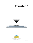
Snapshot Use on Dimmer Outdoor Use Sound Activated DMX Master/Slave 12 V External Power Supply Replaceable Fuse User Serviceable Duty Cycle User Manual 3000 N 29th Ct, Hollywood, FL 33020 U.S.A. (800) 762-1084 – (954) 929-1115 FAX (954) 929-5560 www.chauvetlighting.com TABLE OF CONTENTS 1. Before You Begin ....................................................................................................................................... 3 WHAT IS INCLUDED ................................................................................................................................................................................ 3 UNPACKING INSTRUCTIONS .................................................................................................................................................................... 3 MANUAL CONVENTIONS ......................................................................................................................................................................... 3 ICONS .................................................................................................................................................................................................. 3 SAFETY INSTRUCTIONS .......................................................................................................................................................................... 4 2. Introduction ................................................................................................................................................ 5 FEATURES ............................................................................................................................................................................................ 5 PRODUCT OVERVIEW (FRONT) ................................................................................................................................................................ 6 PRODUCT OVERVIEW (REAR PANEL) ....................................................................................................................................................... 7 3. Setup ........................................................................................................................................................... 8 SETTING UP THE SYSTEM ....................................................................................................................................................................... 8 MOUNTING............................................................................................................................................................................................ 8 Orientation ................................................................................................................................................................ 8 Rigging ..................................................................................................................................................................... 8 FIXTURE LINKING................................................................................................................................................................................... 8 Data Cabling ............................................................................................................................................................. 8 DMX Data Cable ....................................................................................................................................................... 8 Cable Connectors ..................................................................................................................................................... 9 3-Pin to 5-Pin Conversion Chart ................................................................................................................................ 9 Setting up a DMX Serial Data Link ............................................................................................................................ 9 4. Operating Instructions............................................................................................................................. 10 RESETTING THE SYSTEM...................................................................................................................................................................... 10 FIXTURE ADDRESSING ......................................................................................................................................................................... 10 PHYSICAL FADER ASSIGNMENT (OPTIONAL SETUP) ................................................................................................................................. 10 PROGRAMMING ................................................................................................................................................................................... 11 Entering program mode .......................................................................................................................................... 11 Create a scene ....................................................................................................................................................... 11 Delete scene ........................................................................................................................................................... 11 CHASE PROGRAMMING ........................................................................................................................................................................ 12 Create a chase ....................................................................................................................................................... 12 Delete a scene/step in a Chase .............................................................................................................................. 12 Delete a Chase ....................................................................................................................................................... 12 PLAYBACK (CHASES/SCENES) .............................................................................................................................................................. 13 Manual run chase ................................................................................................................................................... 13 Running in Sound-Mode ......................................................................................................................................... 13 Running in Auto-Mode ............................................................................................................................................ 13 Manual run scene ................................................................................................................................................... 14 Blackout .................................................................................................................................................................. 14 Strobe ..................................................................................................................................................................... 14 CONTACT US ...................................................................................................................................................................................... 14 5. Appendix................................................................................................................................................... 15 DMX PRIMER ..................................................................................................................................................................................... 15 GENERAL MAINTENANCE...................................................................................................................................................................... 15 RETURNS PROCEDURE ........................................................................................................................................................................ 16 CLAIMS .............................................................................................................................................................................................. 16 GENERAL TROUBLESHOOTING .............................................................................................................................................................. 16 TECHNICAL SPECIFICATIONS ................................................................................................................................................................ 17 Obey™ 8 User Manual 2 3/4/2010 3:12 PM 1. BEFORE YOU BEGIN What is included 1 x Obey™ 8 Controller 1 x 12 VDC, 500 mA Power Adapter 1 x Manual 1 x Warranty Card Unpacking Instructions Immediately upon receiving a fixture, carefully unpack the carton, check the contents to ensure that all parts are present, and have been received in good condition. Notify the shipper immediately and retain packing material for inspection if any parts appear damaged from shipping or the carton itself shows signs of mishandling. Save the carton and all packing materials. In the event that a fixture must be returned to the factory, it is important that the fixture be returned in the original factory box and packing. Manual Conventions CHAUVET manuals use the following conventions to differentiate certain types of information from the regular text. MEANING CONVENTION [10] A DIP switch to be configured <Menu> A key to be pressed on the fixture’s control panel 1~512 A range of values 50/60 A set of values of which only one can be chosen Settings MENU > Settings ON A menu option not to be modified (for example, showing the operating mode/current status) A sequence of menu options to be followed A value to be entered or selected Icons This manual uses the following icons to indicate information that requires special attention on the part of the user. MEANING ICONS This paragraph contains critical installation, configuration or operation information. Failure to comply with this information may render the fixture partially or completely inoperative, cause damage to the fixture or cause harm to the user or technician. This paragraph contains important installation or configuration information. Failure to comply with this information may prevent the fixture from functioning correctly. This paragraph contains useful, although not critical, information. Obey™ 8 User Manual 3 3/4/2010 3:12 PM Safety Instructions Please read these instructions carefully, which includes important information about the installation, usage and maintenance of your fixture. Keep this User Manual for future consultation. If you sell the unit to another user, be sure that they also receive this instruction booklet. Always make sure that you are connecting to the proper voltage and that the line voltage you are connecting to is not higher than that stated on decal or rear panel of the fixture. This product is intended for indoor use only! To prevent risk of fire or shock, do not expose fixture to rain or moisture. Make sure there are no flammable materials close to the unit while operating. In the event of serious operating problem, stop using the unit immediately. Never try to repair the unit by yourself. Repairs carried out by unskilled people can lead to damage or malfunction. Please contact the nearest authorized technical assistance center. Don’t connect the device to a dimmer pack. Make sure power cord is never crimped or damaged. Never disconnect power cord by pulling or tugging on the cord. Do not operate this device in more than 113° F (45° C) ambient temperature conditions. There are no user serviceable parts inside the unit. Do not open the housing or attempt any repairs yourself. In the unlikely event your unit may require service, please contact CHAUVET at: 954-9291115. Obey™ 8 User Manual 4 3/4/2010 3:12 PM 2. INTRODUCTION The Obey™ 8 is a compact, universal intelligent lighting controller, designed for use with LED wash fixtures (dimming, color mixing). It allows for up to 32 channels of DMX with control of up to four fixtures. Up to eight scenes and eight chases may be programmed. It has a specialized blackout feature, to be utilized with wash fixtures. Features Universal DMX-512 compact LED controller Controls up to four intelligent lights of up to eight channels each 32 DMX channels of control Eight sets of chases containing up to 99 steps each (200 steps max) Playback options include automatic, sound-activated or manual Four fader flash buttons for momentary on Adjustable audio sensitivity Sequential linking of chases Grab any fixture on the fly DMX polarity selector Obey™ 8 User Manual 5 3/4/2010 3:12 PM Product Overview (front) 1 2 15 11 5 6 14 13 12 10 3 7 4 16 9 8 ITEM BUTTON OR FADER FUNCTION 1 Fixtures select buttons Fixture selection 2 Scenes select buttons Universal bump buttons representing scene location for storage and selection 3 Channel faders For adjusting DMX values, Ch 1~4 can be adjusted immediately after pressing the respective fixture select button, Ch 5~8 after pressing the Page select button 4 Page button Press to toggle between pages of control: 1~4, 5~8 5 Program button Used to enter program mode 6 Patch/Down button Used to enter Physical Fader Assignment mode 7 Mode/Up button Used to activate Auto, Sound, or Manual mode and as the Up key to scroll through the different steps in a Chase 8 Step display Status window displays pertinent operational data 9 Step/del button Sets the chase speed by tapping, and toggles between values and percentages. 10 Blackout button Reduces all DMX values to zero; used with the Fade Time fader 11 Chases buttons Chase memory 1~8 12 Run/Strobe Speed fader This will adjust the hold time of a scene or a step within a chase; it also adjusts the strobe speed, when the strobe button is activated 13 Fade Time fader Also considered a cross-fade, sets the fade time between two scenes in a chase, or adjust blackout speed 14 Audio Sensitivity fader Sets the audio sensitivity level 15 Strobe button Used with the Run/Strobe Speed fader to activate/modify the strobe function 16 Channel Flash buttons Used to provide a momentary output of the DMX channel to 100%/255 Obey™ 8 User Manual 6 3/4/2010 3:12 PM Product Overview (rear panel) 10B 17 Item 18 19 20 Button or Fader Function 17 Back panel sticker Shows the rear panel connections/switches and their function 18 DMX polarity switch Used to change signal polarity 19 DMX output connector DMX control signal output 20 DC Input jack Main DC power input 21 Power On/Off switch Used to power on/off the controller Obey™ 8 User Manual 7 21 3/4/2010 3:12 PM 3. SETUP Setting up the System 1) Place the Obey™ 8 on a level surface. 2) Plug the AC to DC power supply into the system back panel and into the mains outlet. 3) Plug in your DMX cable(s) to your fixture, as described in the respective fixture’s manual. For a quick overview of DMX, see the “DMX Primer” section. Mounting Orientation This fixture may be mounted in any safe position, provided there is adequate room for ventilation. Rigging When selecting an installation location, consider access and routine maintenance. Never mount the controller in places where it may be exposed to rain, high humidity, extreme temperature changes or restricted ventilation. Fixture Linking You will need a serial data link to run light shows of one or more fixtures using a DMX controller or to run synchronized shows on two or more fixtures set to a master/slave operating mode. The combined number of channels required by all the fixtures on a serial data link determines the number of fixtures the data link can support. Fixtures on a serial data link must be daisy chained in one single line. To comply with the EIA485 standard, no more than 32 fixtures should be connected on one data link. Connecting more than 32 fixtures on one serial data link without the use of a DMX optically-isolated splitter may result in deterioration of the digital DMX signal. Maximum recommended serial data link distance: 500 m (1640 ft) Maximum recommended number of fixtures on a serial data link: 32 Data Cabling To link fixtures together you must obtain data cables. You can purchase CHAUVET certified DMX cables directly from a dealer/distributor or construct your own cable. If you choose to create your own cable please use data-grade cables that can carry a high quality signal and are less prone to electromagnetic interference. DMX Data Cable Use a Belden© 9841 or equivalent cable which meets the specifications for EIA RS-485 applications. Standard microphone cables cannot transmit DMX data reliably over long distances. The cable must have the following characteristics: Type: shielded, 2-conductor twisted pair Maximum capacitance between conductors: 30 pF/ft Maximum capacitance between conductor and shield: 55 pF/ft Maximum resistance: 20 ohms/1000 ft Nominal impedance: 100 ~ 140 ohms Obey™ 8 User Manual 8 3/4/2010 3:12 PM Cable Connectors Cabling must have a male XLR connector on one end and a female XLR connector on the other end. COMMON INPUT 1 3 2 1 3 2 DMX + DMX Resistance 120 ohm ¼ W between pin 2 (DMX -) and pin 3 (DMX +) on the output of the last fixture. 1 3 2 DMX connector configuration - OUTPUT To avoid signal transmission problems and interference, it is always advisable to connect a DMX signal terminator. Do not allow contact between the common and the fixture’s chassis ground. Grounding the common can cause a ground loop, and your fixture may perform erratically. Test cables with an ohmmeter to verify correct polarity and to make sure the pins are not grounded or shorted to the shield or each other. 3-Pin to 5-Pin Conversion Chart If you use a controller with a 5-pin DMX output connector, you will need to use a 5-pin to 3-pin adapter, such as CHAUVET Model No: DMX5M, or DMX5F. The chart below details a proper cable conversion: 3-PIN TO 5-PIN CONVERSION CHART Conductor 3 Pin Female (Output) 5 Pin Male (Input) Ground/Shield Pin 1 Pin 1 Data ( - ) signal Pin 2 Pin 2 Data ( + ) signal Pin 3 Pin 3 Not used Pin 4 Not used Pin 5 Setting up a DMX Serial Data Link Universal DMX Controller 1. Connect the (male) 3-pin connector side of the DMX cable to the output (female) 3-pin connector of the controller. 2. Connect the end of the cable coming from the controller which will have a (female) 3-pin connector to the input connector of the next fixture consisting of a (male) 3-pin connector. This drawing provides a general illustration of the DMX input/output panel of a lighting fixture. 3. Then, proceed to connect from the output as stated above to the input of the following fixture and so on. CHAUVET Certified DMX Data Cables Order Code Description DMX1.5 DMX Cable 1.5 m/4.9 ft DMX4.5 DMX Cable 4.5 m/14.8 ft DMX10 DMX Cable 10 m/32.8 ft Continue the link Obey™ 8 User Manual 9 3/4/2010 3:12 PM 4. OPERATING INSTRUCTIONS Resetting the System This will reset the controller to its factory defaults. This will erase all programs and settings. 1) Tap <PROGRAM> and <STEP/DEL>. 2) All LEDs will blink to indicate a successful reset. (Note: This process may take up to 15 seconds) Fixture Addressing The Obey™ 8 is programmed to control eight channels of DMX per fixture. Therefore, the fixtures you wish to control with the corresponding <FIXTURES> on the unit must be spaced eight channels apart (check the respective fixture’s manual for how to enter the information into the fixture). FIXTURE # 1 2 3 4 DEFAULT DMX STARTING ADDRESS 1 9 17 25 DIP SWITCH SETTINGS 1 1, 4 1, 5 1, 4, 5 Failure to use these DMX assignments may cause a lack of control of the fixtures. Physical Fader Assignment (optional setup) Use this feature to combine or unify fixture control attributes for different fixtures. For example, if you were controlling four fixtures, each with their own different channel configurations, you could combine the channels to work with the same faders. Therefore, channels 1, 2, and 3 could control red, green, and blue, respectively. Action Notes 1) Press and hold <PATCH> for five seconds to access the fader assignment mode. 2) Press a <FIXTURE> button that represents the fixture whose faders you would like to reassign. All physical faders can be re-assigned to output on a different DMX channel. Faders are given a channel number and are labeled on the surface of the controller as such. 3) Press a <FLASH> button which corresponds to the fader you would like to move the DMX channel to. You may assign multiple DMX channels to a single fader. 4) Press the <SCENE> button which corresponds to the DMX channel (1~8) to move to that channel fader selected in step 3. You may select the <PAGE> button to select a fader from a different page. 5) All LEDs indicators will flash to confirm a successful copy. 6) Repeat steps 2~4 as often as necessary. 7) Press and hold <PATCH> for five seconds to exit the fader assignment mode. If you wish to delete the fader assignment of a DMX channel, you may follow the instructions below. 1) Press and hold <PATCH> for five seconds to access the fader assignment mode. 2) Press <STEP/DEL> and the <SCENE> button at the same time. 3) All LEDs will flash, indicating successfully removal from the DMX channel. 4) Press and hold <PATCH> for five seconds to exit the fader assignment mode. Obey™ 8 User Manual 10 You may NOT assign a fader to a channel from a different <FIXTURE>. When you delete the fader assignment of a DMX channel, this will completely remove the DMX assignment of the fader. It will NOT revert the channel to the defaults. 3/4/2010 3:12 PM Programming A chase is a sequence of scenes/steps. In the Obey™ 8, eight chases may be created, with up to 99 steps per chase. Entering program mode Press <PROGRAM> for five seconds, until the program LED indicator remains on. This indicates that the controller is in programming mode. To exit program mode, repeat the step by holding <PROGRAM> for five seconds, until the program LED indicator remains off. Create a scene A scene is a static lighting state. There are eight scenes available total. Notes Action Deselect <BLACKOUT> if LED is lit. 1) Enter program mode. 2) Select a <FIXTURE> to program. 3) Compose a look by moving the <FADERS>. (Changes in fixture attribute such as colors). Press <PAGE> to access channels 5~8 on the faders. 4) To program another <FIXTURE>, deselect the <FIXTURE> you have just finished programming, and then select another <FIXTURE> to program. A <FIXTURE> button represents one lighting fixture. 5) Repeat steps 2~5 until you have your look. 6) Press <PROGRAM>. 7) Select a <SCENES> button to store. All LEDs will blink. The relevant <SCENE> LED will now be on. 8) Repeat steps 2~7 to record more scenes. ( Read Important notes on the right ->) 9) Exit program mode. You can access channels 5~8 by pressing <PAGE> select. This is necessary for fixtures that use more than 16 channels of control. When switching pages it will be necessary to move previously moved faders up then down to activate. Pressing the same <FIXTURE> again will hold the parameters changed for that fixture in the program scene. Delete scene Action Notes 1) Enter program mode. When a scene is removed, the button may still be activated. However, this will be blank. 2) Press and hold <STEP/DEL>, while pressing the <SCENES> you want to delete. 3) All LEDs will flash, indicating a successful delete. 4) Exit program mode. Obey™ 8 User Manual 11 3/4/2010 3:12 PM Chase Programming A chase is created by using previously created scenes. Scenes become steps in a chase and can be arranged in any order you choose. You may use the same scene multiple times in a chase. Create a chase A chase can contain up to 99 scenes as steps. The term steps and scenes are used interchangeably. You may program up to eight chases with the Obey™ 8. Action Notes 1) Enter program mode. The LED display will indicate which step you are currently recording to. 2) Press the <CHASE> (1~8) button you wish to program. 3) You may select the <SCENE> to insert (or, you may select a <FIXTURE> and build a look, using the faders). 4) Tap <PROGRAM> to store. All LEDs will flash. 5) Repeat steps 3~4 to add additional steps in the chase. Up to 99 steps can be recorded. 6) Exit program mode. You may use <MODE/UP> and <PATCH/DOWN> to scroll through the steps in the chase. What is displayed on the fixtures will be saved when you record the step into the chase. Delete a scene/step in a Chase Action Notes 1) Enter program mode. Remember that scene and steps are used interchangeably. 2) Press the desired <CHASE> (1~8) that contains the scene to be deleted. 3) Use <MODE/UP> and <PATCH/DOWN> to switch to the desired step. 4) Press <STEP/DEL> to delete the step. 5) Exit program mode. Delete a Chase Action Notes 1) Enter program mode. Scenes will remain programmed on the controller. Only the chase is affected. 2) Press the <CHASE> (1~8) to be deleted. 3) Press and hold <STEP/DEL> and then the respective <CHASE>. 4) Then release to delete the chase. All LEDs will blink. 5) Exit program mode. Obey™ 8 User Manual 12 3/4/2010 3:12 PM Playback (Chases/Scenes) Manual run chase When power is first turned ON, the controller will be in Auto mode. Notes Action 1) Press <MODE/UP> to select Manual mode. 2) Select the <CHASE> to run. 3) Press <STEP/DEL> to navigate the different steps in the chase, in increasing numeric order. This mode does not affect the scenes. They will still operate separately, in an HTP (highest takes priority) operation. The LED display will note the current step in the chase. If multiple chases are selected, they will play back in sequential order. You may select a fixture and override any scene or chase playing back at any time. Running in Sound-Mode When power is first turned ON, the controller will be in Auto mode. Action Notes 1) Press <MODE/UP> to select Sound mode. In the Sound mode, programs will be triggered by the sound using its built-in microphone. 2) Select the <CHASE> to run. 3) Adjust the <AUDIO> fader to adjust the microphone sensitivity. This mode does not affect the scenes. They will still operate separately, in an LTP (last takes priority) operation. The LED display will note the current step in the chase. If multiple chases are selected, they will play back in sequential order. You may select a fixture and override any scene or chase playing back at any time. Running in Auto-Mode When power is first turned ON, the controller will be in Auto mode. Notes Action 1) Press <MODE/UP> to select Auto mode. 2) Select the <CHASE> to run. In the Auto mode, programs will be triggered by controllers fade and speed time as set on the faders. 3) Adjust the <RUN/STROBE SPEED> fader to adjust the speed at which the chase will playback. This mode does not affect the scenes. They will still operate separately, in an LTP (last takes priority) operation. 4) Adjust the <FADE TIME> fader to adjust the transition of the chase from one step to another. The LED display will note the current step in the chase. If multiple chases are selected, they will play back in sequential order. The Fade Time fader will add time to the playback of the chase. You may use <STEP/DEL> to manually move forward to the proceeding step in the chase. You may select a fixture and override any scene or chase playing back at any time. Obey™ 8 User Manual 13 3/4/2010 3:12 PM Manual run scene Action Notes 1) Select a <SCENE>. This will not operate in HTP (highest take priority) when stacking scenes. 2) The respective LED will remain lit/on, while the scene is activated. 3) If desired, multiple scenes may be activated. 4) Press the respective <SCENE> a second time to deactivate it. You may select a fixture and override any scene or playing back at any time. Blackout When pressing <BLACKOUT>, the <FADE TIME> fader will affect the function. Notes Action 1) 2) Adjust the <FADE TIME> to select the speed at which the fixture(s) will fade out. Select <BLACKOUT> to activate the function. This function will work in ANY mode. If the fade time is already being used for a chase running in Auto mode, then pressing <BLACKOUT> will activate the function at the fade time that the chase is currently running. Strobe The strobe function can be activated in ANY mode. Notes Action This function will work in ANY mode. 1) Press <STROBE>. 2) Adjust the <RUN/STROBE SPEED> fader to the desired strobing speed. 3) You may press <STROBE> again to use the <RUN/STROBE SPEED>fader for playback speed adjustment. In order to deactivate this function, the <STROBE> must be activated. Then, move the <RUN/STROBE SPEED> fader fully down, or to 10 m. Contact Us World Wide General Information CHAUVET 3000 North 29th Court Hollywood, FL 33020 voice: 954.929.1115 fax: 954.929.5560 toll free: 800.762.1084 Technical Support CHAUVET 3000 North 29th Court Hollywood, FL 33020 voice: 954.929.1115 (Press 4) fax: 954.929.5560 (Attention: Service) World Wide Web www.chauvetlighting.com Obey™ 8 User Manual 14 3/4/2010 3:12 PM 5. APPENDIX DMX Primer There are 512 channels in a DMX connection. Channels may be assigned in any manner. A fixture capable of receiving DMX will require one or a number of sequential channels. The user must assign a starting address on the fixture that indicates the first channel reserved in the controller. There are many different types of DMX controllable fixtures and they all may vary in the total number of channels required. Choosing a start address should be planned in advance. Channels should never overlap. If they do, this will result in erratic operation of the fixtures whose starting address is set incorrectly. You can however, control multiple fixtures of the same type using the same starting address as long as the intended result is that of unison movement or operation. In other words, the fixtures will be slaved together and all respond exactly the same. DMX fixtures are designed to receive data through a serial Daisy Chain. A Daisy Chain connection is where the DATA OUT of one fixture connects to the DATA IN of the next fixture. The order in which the fixtures are connected is not important and has no effect on how a controller communicates to each fixture. Use an order that provides for the easiest and most direct cabling. Connect fixtures using shielded two conductor twisted pair cable with three pin XLR male to female connectors. The shield connection is pin 1, while pin 2 is Data Negative (S-) and pin 3 is Data positive (S+). General Maintenance To maintain optimum performance and minimize wear, fixtures should be cleaned frequently. Usage and environment are contributing factors in determining frequency. As a general rule, fixtures should be cleaned at least twice a month. Dust build up reduces light output performance and can cause overheating. This can lead to reduced lamp life and increased mechanical wear. Be sure to power off fixture before conducting maintenance. Unplug fixture from power. Use a vacuum or air compressor and a soft brush to remove dust collected on external vents. Clean all glass when the fixture is cold with a mild solution of glass cleaner or Isopropyl Alcohol and a soft lint free cotton cloth or lens tissue. Apply solution to the cloth or tissue and drag dirt and grime to the outside of the lens. Gently polish optical surfaces until they are free of haze and lint. The cleaning of external optical lenses and/or mirrors must be carried out periodically to optimize light output. Cleaning frequency depends on the environment in which the fixture operates. Damp, smoky or particularly dirty surroundings can cause greater accumulation of dirt on the unit’s optics. Clean with soft cloth using normal glass cleaning fluid. Clean the external optics at least every 20 days. Clean the fixture at least every 30/60 days. Always dry the parts carefully after cleaning them. Never spin a fan using compressed air. Obey™ 8 User Manual 15 3/4/2010 3:12 PM Returns Procedure Returned merchandise must be sent prepaid and in the original packing; call tags will not be issued. Package must be clearly labeled with a Return Merchandize Authorization Number (RMA #). Products returned without the RMA # will be refused. Call CHAUVET and request an RMA # prior to shipping the fixture. Be prepared to provide the model number, serial number and a brief description of the cause for the return. Be sure to pack fixture properly; any shipping damage resulting from inadequate packaging is the customer’s responsibility. As a suggestion, proper UPS packing or double-boxing is always a safe method to use. CHAUVET reserves the right to use its own discretion to repair or replace product(s). If you are given an RMA #, please include the following information on a piece of paper inside the box: 1) Your name 2) Your address 3) Your phone number 4) The RMA # 5) A brief description of the symptoms Claims Damage incurred in shipping is the responsibility of the shipper; therefore, the damage must be reported to the carrier upon receipt of merchandise. It is the customer's responsibility to notify and submit claims with the shipper in the event that a fixture is damaged due to shipping. Any other claim for items such as missing component/part, damage not related to shipping, and concealed damage, must be made within seven (7) days of receiving merchandise. General Troubleshooting SYMPTOM SOLUTION(S) Scenes not playing back Check to confirm that the blackout function is not activated. Check the strobe speed by pressing <STROBE> and adjusting the speed on the fader Fixtures are strobing Chase is too slow in Sound mode Check the Audio sensitivity fader Chase is too slow in Auto mode Check the Run/Strobe speed and Fade Time sensitivity faders Different fixtures are not aligning with the DMX channels Modify the physical Fader Assignments Blackout is not activating instantly Fixtures are not responding to controller output Obey™ 8 User Manual This controller has a special feature, which allows the blackout feature to work with an adjustable fade time. This is adjusted using the Fade Time fader. Check DMX address settings Check DMX cables Check the DMX polarity switch. 16 3/4/2010 3:12 PM Technical Specifications WEIGHT & DIMENSIONS Length ........................................................................................................................ 14.7 in (373 mm) Width............................................................................................................................ 6.1 in (156 mm) Height ............................................................................................................................ 2.2 in (56 mm) Weight........................................................................................................................... 3.9 lbs (1.8 kg) POWER Operating Range ................................................................................................. 12 VDC, 500 mA max AC to DC power adapter (100~240 VAC, 50/60 Hz) ................................................................ Provided THERMAL Maximum ambient temperature ...................................................................................... 113° F (45° C) CONTROL & PROGRAMMING Data output ........................................................................................ locking 3-pin XLR female socket Data pin configuration ............................................................................ pin 1 shield, pin 2 (-), pin 3 (+) Protocols .................................................................................................................. USITT DMX512-A ORDERING INFORMATION Obey™ 8 Controller .................................................................................................................. OBEY8 WARRANTY INFORMATION Warranty ........................................................................................................... 2-year limited warranty ©CHAUVET, 2009, All Rights Reserved Information and specifications in this user manual are subject to change without notice. CHAUVET assumes no responsibility or liability for any errors or inaccuracies that may appear in this document. Obey™ 8 User Manual 17 3/4/2010 3:12 PM