1
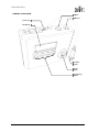
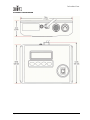
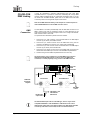
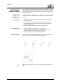
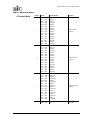
COLORADO™ CONTROLLER User Manual Edition Notes Edition Notes CHAUVET released this edition of the COLORado™ Controller (COLOR-CON) User Manual Rev. 01d in August 2009. Copyright Notice No person, group of persons or entity can reproduce any part of this publication, store it in a retrieval system, or transmit it, in any form or by any means, whether mechanical, electronic, photocopying, recording, or otherwise, without prior written permission of CHAUVET. The COLORado™ Controller User Manual Rev. 01d covers the description, safety precautions, installation, programming, operation and maintenance of the CHAUVET COLORado™ Controller. © Copyright 2009 CHAUVET All rights reserved Printed in the People’s Republic of China Disclaimers CHAUVET believes that the information contained in this manual is accurate in all respects. However, CHAUVET assumes no responsibility for any error or omissions in this document. CHAUVET reserves the right to revise this document and to make changes from time to time in the content hereof without obligation of CHAUVET to notify any person or company of such revision or changes. This does not constitute in any way a commitment by CHAUVET to make such changes. CHAUVET may issue a revision of this manual or a new edition of it to incorporate such changes. Trademarks COLORado™ is a trademark of CHAUVET. All other products names, brand names, or companies mentioned in the document that are not directly or indirectly related with CHAUVET may be trademarks or enabled trademarks of their respective companies. Intended Audience Chauvet provides the COLORado™ Controller User Manual Rev. 01d with each COLORado™ Controller unit. Any person in charge of installing, operating and/or maintaining the COLORado™ Controller should read this manual in its entirety before installing, operating or maintaining the COLORado™ Controller. CHAUVET Publications Hot Line If you have any comments about the accuracy of this document or general suggestions regarding how we can improve it, please call us at (800) 762-1084 (US callers) or +1-954-929-1115 (international callers), ext. 43. Document Revision The latest versions of all CHAUVET manuals are available at CHAUVET’s Web Site (www.chauvetlighting.com). The COLORado™ Controller User Manual Rev. 01d supersedes all previous versions of this manual. Please discard any older versions of this manual you may have, whether in printed or electronic format, and replace them with this version. Unit at a Glance Use on Dimmer Outdoor Use Sound Activated DMX Master/Slave COLORado™ Controller User Manual - Rev. 01d Auto Programs 12 VDC, 500 mA Replaceable Fuse User Serviceable Duty Cycle August 20, 2009 Table of Contents TABLE OF CONTENTS 1. Before you Begin ...................................................................................................................................... 1 WHAT IS INCLUDED ..................................................................................................................................................................................... 1 UNPACKING INSTRUCTIONS ......................................................................................................................................................................... 1 TEXT CONVENTIONS ................................................................................................................................................................................... 1 ICONS ....................................................................................................................................................................................................... 1 SAFETY INSTRUCTIONS ............................................................................................................................................................................... 2 2. Introduction ............................................................................................................................................... 3 SYSTEM DESCRIPTION ................................................................................................................................................................................ 3 FEATURES ................................................................................................................................................................................................. 3 DMX CHANNEL SUMMARY .......................................................................................................................................................................... 3 PRODUCT OVERVIEW.................................................................................................................................................................................. 4 PRODUCT DIMENSIONS ............................................................................................................................................................................... 5 3. Setup .......................................................................................................................................................... 6 AC POWER................................................................................................................................................................................................ 6 FUSE REPLACEMENT .................................................................................................................................................................................. 6 COLOR-CON DMX LINKING ..................................................................................................................................................................... 7 DMX Connection....................................................................................................................................................... 7 COLOR-CON FIXTURE LINKING ................................................................................................................................................................. 8 Single Row Application ............................................................................................................................................. 8 Standard Block Application ....................................................................................................................................... 9 Repeated Row Block Application ............................................................................................................................ 10 MOUNTING............................................................................................................................................................................................... 11 Orientation .............................................................................................................................................................. 11 Rigging ................................................................................................................................................................... 11 COLOR-CON Mounting .......................................................................................................................................... 11 4. Operating Instructions ........................................................................................................................... 12 CONTROL PANEL DESCRIPTION ................................................................................................................................................................. 12 Navigation Functions .............................................................................................................................................. 12 COLOR-CON MENU MAP ....................................................................................................................................................................... 13 PROGRAMMING PROCEDURE ..................................................................................................................................................................... 14 Wash Program Usage............................................................................................................................................. 14 Wash Program Editing ............................................................................................................................................ 14 Exiting Wash Program ............................................................................................................................................ 14 Effect Program Usage............................................................................................................................................. 14 Effect Program Editing ............................................................................................................................................ 15 Exiting Effect Program ............................................................................................................................................ 15 Custom Program Usage.......................................................................................................................................... 15 Custom Program Editing ......................................................................................................................................... 15 Exiting Custom Program ......................................................................................................................................... 17 Play Schedule ......................................................................................................................................................... 17 Clock Usage ........................................................................................................................................................... 18 Time & Date Setting ................................................................................................................................................ 18 Schedule................................................................................................................................................................. 18 Schedule Configuration ........................................................................................................................................... 19 Exiting Schedule Configuration ............................................................................................................................... 19 Settings .................................................................................................................................................................. 19 Password Setting .................................................................................................................................................... 21 Password Enabling ................................................................................................................................................. 21 Password Disabling ................................................................................................................................................ 21 Password Usage..................................................................................................................................................... 21 Factory Default Values ......................................................................................................................................... 22 DMX CHANNEL VALUES ........................................................................................................................................................................... 23 4-Channel Mode ..................................................................................................................................................... 23 5. Technical Information............................................................................................................................. 24 GENERAL MAINTENANCE ........................................................................................................................................................................... 24 COLOR-CON SERVICE MAINTENANCE GUIDE ........................................................................................................................................... 25 RETURNS PROCEDURE ............................................................................................................................................................................. 26 CLAIMS ................................................................................................................................................................................................... 26 August 20, 2009 a COLORado™ Controller User Manual - Rev. 01d Table of Contents CONTACT US ........................................................................................................................................................................................... 26 TECHNICAL SPECIFICATIONS ..................................................................................................................................................................... 27 6. Appendix .................................................................................................................................................. 28 DMX PRIMER .......................................................................................................................................................................................... 28 The Physical Medium ............................................................................................................................................. 28 The Signals............................................................................................................................................................. 28 The functions .......................................................................................................................................................... 28 DMX CONFIGURATION.............................................................................................................................................................................. 28 Starting Address ..................................................................................................................................................... 28 Personalities ........................................................................................................................................................... 28 Assigning Addresses .............................................................................................................................................. 29 DMX Universes ....................................................................................................................................................... 29 DMX CONNECTIVITY ................................................................................................................................................................................ 29 Fixture Location ...................................................................................................................................................... 29 Number of Fixtures ................................................................................................................................................. 29 Making your Own DMX Cable ................................................................................................................................. 30 DMX Cable Characteristics ..................................................................................................................................... 30 DMX Cable Connectors .......................................................................................................................................... 30 3-Pin to 5-Pin Conversion Chart ............................................................................................................................. 30 SIZING THE CIRCUIT BREAKERS ................................................................................................................................................................. 31 Using the Spec Sticker ........................................................................................................................................... 31 Using the Watts/Volts Method................................................................................................................................. 31 Considering the Power Factor................................................................................................................................. 31 Using the Volt Amps Method .................................................................................................................................. 31 Selecting the Circuit Breaker .................................................................................................................................. 31 COLORado™ Controller User Manual - Rev. 01d b August 20, 2009 Before you Begin 1. Before you Begin What is Included Unpacking Instructions • One COLORado™ Controller (COLOR-CON) • • • • One external voltage adapter (12 VDC output) One IP66 to DMX adapter One warranty card One user manual Immediately upon receiving a fixture, carefully unpack the carton, check the contents to ensure that all parts are present, and have been received in good condition. If any parts appear damaged from shipping or the carton itself shows signs of mishandling, notify the shipper immediately. In addition, retain the box and all the packing material for inspection. In any event, save the carton and all packing material because, in case that you have to return the fixture to the factory, you will have to do so in its original factory box and packing. Text Conventions CHAUVET manuals use the following text conventions within the regular text as well as inside tables. MEANING CONVENTION 1~512 A range of values 50/60 A set of mutually exclusive values in the text [10] A DIP switch to be configured A key to be pressed on the fixture’s control panel <SET> A menu option that can be selected but not modified Settings A sequence of menu options to be followed MENU > Settings [1~10] A range of menu values of which one can be selected Yes/No A set of mutually exclusive menu options to choose A value to be entered or selected ON Icons CHAUVET manuals use the following icons to indicate information that requires special attention on the part of the user. MEANING ICONS This paragraph contains critical installation, configuration or operation information. Failure to comply with this information may render the fixture partially or completely inoperative, cause damage to the fixture or cause harm to the user. This paragraph contains important installation or configuration information. Failure to comply with this information may prevent the fixture from functioning correctly. This paragraph reminds you of useful, although not critical, information. August 20, 2009 1 COLORado™ Controller User Manual - Rev. 01d Before you Begin Safety Instructions Please read the following instructions carefully because they include important safety information about the installation, usage and maintenance of this product. There are no user serviceable parts inside the COLORado™ Controller. Any reference to servicing this unit you may find from now on in this User Manual will only apply to properly CHAUVET certified technicians. Do not open the housing or attempt any repairs unless you are one of them. In the unlikely event that your COLORado™ Controller may require service, please contact CHAUVET at (954) 923-3680. • Keep this manual for future consultation. If you sell the COLORado™ Controller to another user, make sure that they also receive this manual. • Always make sure that you are connecting the controller’ external voltage adapter to the proper voltage, as per the specifications in this manual or on the controller. • Always disconnect the controller’ external voltage adapter from the power source before servicing. • This product is for indoor use only! To prevent risk of fire or shock, do not expose the controller or its external voltage adapter to rain or moisture. • Make sure there are no flammable materials close to the controller or the fixture(s) it controls while operating. • Always secure the controlled fixture(s) to a fastening device using a safety chain. • Maximum ambient temperature (Ta) is 104° F (40° C). Do not operate the fixture at a higher temperature. • In the event of a serious operating problem, stop using the controller or the fixture(s) immediately! • Never connect the COLORado™ controller to a dimmer pack. • Make sure the controller’s external voltage adapter housing or cable are not cracked, crimped or damaged. • Never disconnect the external voltage adapter by pulling or tugging on the power cable. • Avoid direct eye exposure to the controlled fixtures’ light sources while they are on. Please refer to all applicable local codes and regulations for proper installation of the COLORado™ Controller or its associated LED fixture(s). COLORado™ Controller User Manual - Rev. 01d 2 August 20, 2009 Introduction 2. Introduction System Description The COLORado™ Controller (COLOR-CON) is the proprietary 4-channel DMX controller for the COLORado™ and COLORdash™ fixtures. It consists of a small stand-alone case and an external 12 VDC voltage adapter. The output for the controlled COLORado™ and COLORdash™ LED fixtures is a 3pin IP66 rated connector at the end of a pigtail cable. The DMX input and output are on the body of the controller and use regular 3-pin XLR connectors. The COLOR-CON controls its associated fixtures using the ID address method, not the regular DMX addressing method. Therefore, the COLOR-CON cannot control the COLORdash™ Accent fixture because this one lacks the ID address feature. The COLOR-CON has a back lit, two-row LCD module and four programming buttons (MODE, SETUP, UP and DOWN) for fixture configuration. The User Manual of those COLORado™ and COLORdash™ fixtures that work with the COLOR-CON may also have a chapter dedicated to its connectivity and operation. Features • 4-channel DMX controllable from a standard DMX controller • 16 editable programs Eight color wash programs Eight effect programs DMX Channel Summary August 20, 2009 • Controls up to 66 units (using ID addressing) • Eight user-programmable shows with 100 steps each • Full RGB color mixing • Control of each pod (COLORado™ 3 only) • Playback schedules via internal clock • LCD display with password protection CHANNEL FUNCTION 1 Wash programs (1~8) 2 Effect programs (1~8) 3 Custom programs (1~8) 4 On/Off 3 COLORado™ Controller User Manual - Rev. 01d Introduction Product Overview DMX In DMX Out Power Input LCD Display Controller Output On/Off Switch Programming Buttons COLORado™ Controller User Manual - Rev. 01d 4 August 20, 2009 Introduction Product Dimensions August 20, 2009 5 COLORado™ Controller User Manual - Rev. 01d Setup 3. Setup AC Power The COLORado™ Controller (COLOR-CON) has an external voltage adapter that provides it with 12 VDC (500 mA minimum). The input voltage for this voltage adapter is set to match the mains voltage in the market where the COLOR-CON will operate. Please refer to the voltage adapter’s manual for more information. Always connect the COLOR-CON and its associated LED fixtures to a protected circuit with an appropriate electrical ground to avoid the risk of electrocution or fire. To determine the power requirements for the COLOR-CON and its associated LED fixtures see the label affixed to the side of the controller or each fixture. Alternatively, you may refer to their respective specifications charts. The listed current rating indicates the maximum current draw during normal operation. Please refer to the Sizing the Circuit Breakers section in the Appendix chapter of this manual. Never connect the COLOR-CON or any of its associated LED fixtures to a rheostat (variable resistor) or dimmer circuit, even if the rheostat or dimmer channel serves only as a 0 to 100% switch. Fuse Replacement The COLOR-CON has no internal fuses. However, the external voltage adapter may have one. Please refer to the external voltage adapter’s manual to see if it has a fuse you may have to change. Refer to the respective COLORado™ LED fixture’s user manual to learn whether they have a fuse you may have to change. When applicable, always disconnect the fixture’s power cord before replacing™ a blown fuse, and always replace it with a fuse of the same type and rating. COLORado™ Controller User Manual - Rev. 01d 6 August 20, 2009 Setup COLOR-CON DMX Linking If using the COLORado™ Controller (COLOR-CON) along with other DMX compatible fixtures, it is possible to control them individually with a single DMX controller. DMX compatible fixtures use a serial data link between them. If you are not familiar with the DMX standard, please refer to the DMX Primer and DMX Connectivity sections in the Appendix chapter of this manual. Refer to the DMX Channel Summary in this chapter for a brief description of what COLOR-CON features can the DMX controller control. DMX Connection The COLORado™ Controller (COLOR-CON) uses the DMX data connection for its DMX 4-channel mode. See the Introduction chapter for a brief description of this mode and the Operation Instructions chapter to learn how to configure the COLORCON controller to work in this mode. The procedure below illustrates a possible connection method. 1. Connect the 3-pin, male connector of the first DMX cable to the DMX Output connector (3-pin, female) of the DMX controller. 2. Connect the 3-pin, female connector of the first DMX cable coming from the controller to the DMX Input connector (3-pin, male) of the COLOR-CON. 3. Connect the 3-pin, male connector of the second DMX cable to the DMX Output connector (3-pin, female) of the COLOR-CON 4. Connect the 3-pin, female connector of the second DMX cable coming from the COLOR-CON to the DMX Input connector of the first DMX compatible fixture. 5. Continue linking the other DMX compatible fixtures in the same way. The figure below is only an example of a possible DMX serial connection. Although the COLOR-CON appears as the first unit in the DMX serial connection, it could be physically in any position of the DMX serial link. Universal DMX Controller First DMX Cable DMX Data Connection Diagram Second DMX Cable COLOR-CON Third DMX Cable First DMX Fixture Next DMX Fixture COLORado™ and COLORdash™ LED fixtures COLOR-CON output cable The COLOR-CON output cable is of the IP66 type, and it is only for those compatible COLORado™ and COLORdash™ LED fixtures it will control. Although this output cable comes with an IP66 to 3-pin XLR adapter, DO NOT connect any other fixture to this cable, but the ones mentioned above. August 20, 2009 7 COLORado™ Controller User Manual - Rev. 01d Setup COLOR-CON Fixture Linking The COLORado™ Controller (COLOR-CON) uses the ID addressing method to control its associated COLORado™ and COLORdash™ LED fixtures. This allows the user to setup the LED fixtures in three basic ways, single row, standard block and repeated row block. Single Row Application In this application, the fixtures appear in a single row. All the fixtures have sequential ascending ID addresses for the COLOR-CON to control each fixture individually. Fixture Setup COLOR-CON Setup Fixture Connection • Set each LED fixture to ID ON or SLAVE, and to STAGE 1 mode (consult the fixture’s user manual) • Do not set the fixture’s DMX address, as the COLOR-CON does not need it. • For Effect and Custom programs, configure the ID address of each fixture in sequential ascending order • For Wash programs, configure all the fixtures as ID address 001. • Refer to the Operating Instructions chapter of this manual. • For Effect programs, limit the Range to the number of actually used ID addresses. For the example below, the Range must be 4. • For Wash programs, use a single ID address, preferably 001. Connect the fixtures in a regular DMX daisy chain as indicated below, ensuring that the first fixture connects to the they COLOR-CON output cable. For a better visual effect, make sure to connect the LED fixtures in the correct order. COLORado™ Controller User Manual - Rev. 01d 8 August 20, 2009 Setup Standard Block Application Fixture Setup COLOR-CON Setup Fixture Connection In this type of application, the fixtures appear in repeated rows of the same length to form a block. For instance, three rows of fixtures with three fixtures per row to form a 3 x 3 block. Each of the fixtures has unique, sequential ascending ID addresses for the COLOR-CON to control each fixture individually. • Set each LED fixture to ID ON or SLAVE, and to STAGE 1 mode (consult the fixture’s user manual) • Do not set the fixture’s DMX address, as the COLOR-CON does not need it. • For Effect and Custom programs, configure the ID address of each fixture in sequential ascending order • For Wash programs, there is not need to set the ID address. • Refer to the Operating Instructions chapter of this manual. • For Effect programs, limit the Range to the number of actually used ID addresses. For the example below, the Range must be 9. • For Wash programs, there is not need to set an ID address. Connect the fixtures in a regular DMX daisy chain as indicated below, ensuring that the first fixture connects to the they COLOR-CON output cable. For a better visual effect, make sure to connect the LED fixtures in the correct order. August 20, 2009 9 COLORado™ Controller User Manual - Rev. 01d Setup Repeated Row Block Application Fixture Setup COLOR-CON Setup Fixture Connection In this type of application, the fixtures appear in repeated rows of the same length to form a block. For instance, three rows of fixtures with three fixtures per row to form a 3 x 3 block. In this application, the fixtures form groups, each with its own sequential ascending ID addresses. This way, the COLOR-CON will control each group of fixtures individually. For other types of effects, you may group the fixtures in columns, diagonal lines, or even place them in random positions within the block. • Set each LED fixture to ID ON or SLAVE, and to STAGE 1 mode (consult the fixture’s user manual) • Do not set the fixture’s DMX address, as the COLOR-CON does not need it. • For Effect and Custom programs, configure the ID address of each fixture in sequential ascending order • For Wash programs, there is not need to set the ID address. • Refer to the Operating Instructions chapter of this manual. • For Effect programs, limit the Range to the number of actually used ID addresses. For the example below, the Range must be 3. • For Wash programs, there is not need to set an ID address. Connect the fixtures in daisy chain as indicated below, ensuring that they are in the correct order for a better visual effect. For a better visual effect, make sure to connect the LED fixtures in the correct order. COLORado™ Controller User Manual - Rev. 01d 10 August 20, 2009 Setup Mounting Orientation Always mount the COLORado™ Controller (COLOR-CON) and its controlled LED fixtures in any safe position while making sure that there is adequate room around them for ventilation. Rigging The COLORado™ Controller (COLOR-CON) consists of a controller unit and an external voltage adaptor that provides 12 VDC, 500 mA minimum. COLOR-CON Mounting • When selecting an installation location for the COLOR-CON or its associated LED fixtures, consider ease of access to each unit for operation, programming adjustments and routine maintenance. • Never mount the COLOR-CON or its associated LED fixtures in places where rain, high humidity, extreme temperature changes or restricted ventilation may affect them. • Make sure that the location where you are mounting the COLOR-CON associated LED fixtures can support their weight. Please see the “Technical Specifications” section of the fixtures’ user manuals for the weight requirement of each fixture. You should mount the COLOR-CON on a flat, dry surface, whether plywood or other suitable material. The COLOR-CON’s detachable baseplate has four holes to accommodate regular screws for this purpose. In any case, remember the recommendations indicated above regarding access to the unit and necessary room for ventilation. The diagram below shows the detachable baseplate and its three nipples. These must slide all the way inside the corresponding slots on the back of the COLORCON to ensure a safe unit rigging. COLOR-CON Output Baseplate Nipples COLOR-CON Mounting Diagram COLOR-CON Mounting screws Make sure there is a suitable power outlet for the COLOR-CON voltage adapter near the location where you will mount the COLOR-CON unit. August 20, 2009 11 COLORado™ Controller User Manual - Rev. 01d Operating Instructions 4. Operating Instructions Control Panel Description The COLORado™ Controller (COLOR-CON) has an LCD display and four buttons to configure its functions. The table below explains the functions of those buttons. Button Function <MODE> Used to access the menu or to return to a previous menu option <SETUP> Selects a menu option <UP> Scrolls through menu options in descending order <DOWN> Used to select and store the current menu or option within a menu Navigation Functions The COLOR-CON navigation functions allow the user to setup all the COLORCON’s parameters, including the access password. Display The COLOR-CON’s LCD Display has two lines. The upper line shows the menu items the user selects from the menu map. While navigating the menu map, only the upper row is active. Menu Level Change To move to the right side of the menu map (next level) press <SETUP>. This will serve to accept the current option and move forward. To move to the left side of the menu map (previous level) press <MODE>. This will return the display to the previous option. In most cases, the COLOR-CON will save the current value on exit, regardless of whether it has changed. Available Options When the user reaches a menu function that has an option to be accepted or changed, the display will show it on its lower row. Select Options To move up or down in the menu map, use <UP> and <DOWN>. This will show the available options for the current menu item. When setting up the password, the <UP> button is also the equivalent of a “1,” whereas the <DOWN> button is the equivalent of a “0.” COLORado™ Controller User Manual - Rev. 01d 12 August 20, 2009 Operating Instructions COLOR-CON Menu Map 1st Level 2nd Level 3rd Level 4th Level 1. Wash Program Wash [1~8] Edit 2. Effect Program Effect [1~8] Edit 3. Custom Program Custom [1~8] 5th Level 6th Level Description Step Time [000~255] N/A Defines the duration of each program step Fade Time [000~255] N/A Defines the fade time for each program step Speed [000~255] N/A Defines the speed of the effect program Scene [001~100] Edit MENU ID address [000~066] Assigns an ID address Step time [000~255] Defines the step duration Fade time [000~255] Defines the fade duration Red [000~255] Defines the level of red Green [000~255] Defines the level of green Blue [000~255] Defines the level of blue Module [000~006] Activate LED module(s) (multi LED module fixtures only) Strobe [000~020] Selects the strobe frequency N/A N/A N/A Activates the pre-configured schedule(s) Time Now dd/mm/yyyy hh:mm:ss N/A N/A Shows current time and date Edit time dd/mm/yyyy N/A Edits time and date 6. Schedule Wash [1~8] Effect [1~8] Custom [1~8] Start End [00:00~23:59] [00:00~23:59] N/A Sets the daily schedule for each Wash, Effect and Custom program 7. Settings DMX address [001~255] N/A N/A Sets the unit’s DMX address Range [002~066] N/A N/A Limits the ID address range Allow edit Yes/No N/A N/A Allows or denies editing Detect device [001~512] N/A N/A Detects a specific device Reset to Factory settings Yes/No N/A N/A Defaults the COLOR-CON to its factory settings Set password Up/Down N/A N/A Sets the unit’s password 4. Play Schedule >>> 5. Clock 8. Password August 20, 2009 hh:mm:ss 13 COLORado™ Controller User Manual - Rev. 01d Operating Instructions Programming Procedure To start programming the COLORado™ Controller (COLOR-CON), the display must show MENU. On power up, MENU shows on the display automatically. However, if someone has already configured the COLOR-CON, its display may be showing the current mode. If MENU does not show on the display, press <MODE> repeatedly until MENU appears. This is the top of the menu map. At this point, <SETUP>, <UP> and <DOWN> will not work. Wash Program Usage • With MENU showing on the display, press <MODE> once. The upper row of the display will show 1. Wash program. • Press <SETUP> to select this option. The upper row of the display will show Wash [1]. • Alternatively, to select any of the other Wash programs (2~8), press <UP> or <DOWN>. The selected Wash program will start playing automatically. Wash Program Editing Fade Time • With the selected Wash program (1~8) showing on the upper row of the display, press <SETUP>. If program editing is set to Yes in the “Settings” section, Edit will show on the display’s lower row. Otherwise, refer to the “Settings” section to enable program editing. Selects the fade time for each step in the program • Press <SETUP> to configure the selected Wash program. Fade time will show on the lower row of the display, along with its current value (001~255). Step Time • Press <UP> or <DOWN> to change the value (1 unit = 1 second). • Once done, press <SETUP> to configure the Step time parameter. Selects the duration of each program step Step time will show on the lower row of the display, along with its current value (001~255). Exiting Wash Program • Press <UP> or <DOWN> to change the value (1 unit = 5 seconds). • Press <MODE> to save the current values. The display will briefly show OK Save on its lower row and it will go back to show the selected Wash program and Edit. • Press <MODE> again to exit Wash Program Editing. The display will show the selected Wash program. • Press <MODE> again to exit to the second menu level. The upper row of the display will show 1. Wash program. Effect Program Usage • With MENU showing on the display, press <MODE> twice. The upper row of the display will show 2. Effect program. • Press <SETUP> to select this option. The upper row of the display will show Effect [1]. • Alternatively, to select any of the other Effect programs (2~8), press <UP> or <DOWN>. The selected Effect program will start playing automatically. COLORado™ Controller User Manual - Rev. 01d 14 August 20, 2009 Operating Instructions Programming Procedure (Cont.) Effect Program Editing Speed • With the selected Effect program (1~8) showing on the upper row of the display, press <SETUP>. If program editing is set to Yes in the “Settings” section, Edit will show on the display’s lower row. Otherwise, refer to the “Settings” section to enable program editing. Selects the speed at which the program executes • Press <SETUP> to configure the selected Effect program. Speed will show on the lower row of the display, along with its current value (001~255). • Press <UP> or <DOWN> to change the value. • Press <MODE> to save the current value. OK Save will show on the lower row of the display. Exiting Effect Program • Press <MODE> to exit Effect Program Editing. The display will briefly show OK Save on its lower row and it will go back to show the selected Effect program and Edit. • Press <MODE> again to exit Effect Program Editing. The display will show the selected Effect program. • Press <MODE> again to exit to the second menu level. The upper row of the display will show 2. Effect program. Custom Program Usage • With MENU showing on the display, press <MODE> three times. The upper row of the display will show 3. Custom program. • Press <SETUP> to select this option. The upper row of the display will show Custom [1]. • Alternatively, to select any of the other Custom programs (2~8), press <UP> or <DOWN>. The selected Custom program will start playing automatically. Custom Program Editing Scene • With the selected Custom program (1~8) showing on the upper row of the display, press <SETUP>. If program editing is set to Yes in the “Settings” section, Edit will show on the display’s lower row. Otherwise, refer to the “Settings” section to enable program editing. Selects a scene in the 000~100 range • Press <SETUP> to configure the selected Custom program. Scene will show on the upper row of the display, along with its current value (001~100). • Press <UP> or <DOWN> to change the scene, if necessary. Any unused scene should have its Step time set to “0.” ID Address Selects the ID address of the fixtures on which this program will operate • Press <SETUP> to configure the ID address. ID address will show on the upper row of the display, along with its current value (001~66). • August 20, 2009 Press <UP> or <DOWN> to change the ID address, if necessary. 15 COLORado™ Controller User Manual - Rev. 01d Operating Instructions Programming Procedure (Cont.) Step Time Selects the duration of each program step • Press <SETUP> to configure the step time. Step time will show on the lower row of the display, along with its current value (000~255). • Press <UP> or <DOWN> to change the value. From “000~010,” the time duration per unit is 0.1 seconds. From “011~255,” the time duration per unit is 1.0 seconds. Fade Time Selects the fade time for each step in the program • Press <SETUP> to configure the fade time. Fade time will show on the lower row of the display, along with its current value (000~255). • Red Press <UP> or <DOWN> to change the value (1 unit = 1 second). Selects the intensity of the red color • Press <SETUP> to configure the red color. Red will show on the upper row of the display, along with its current value (000~255). • Green Press <UP> or <DOWN> to change the value. Selects the intensity of the green color • Press <SETUP> to configure the green color. Green will show on the upper row of the display, along with its current value (000~255). • Blue Press <UP> or <DOWN> to change the value. Selects the intensity of the blue color • Press <SETUP> to configure the blue color. Blue will show on the upper row of the display, along with its current value (000~255). • Press <UP> or <DOWN> to change the value. By adjusting the red, green and blue values, the user can define 16,777,216 possible color combinations. COLORado™ Controller User Manual - Rev. 01d 16 August 20, 2009 Operating Instructions Programming Procedure (Cont.) Module Enables the various LED modules in the COLORado™ 3 and COLORado™ 6 as well as in the COLORdash™ Batten and COLORdash™ Quad • Press <SETUP> to configure the Module parameter. Module will show on the upper row of the display, along with its current value (000~006). • Press <UP> or <DOWN> to change the value as follows: SETTING COLORADO™ 3 COLORDASH™ BATTEN 0 Modules 1, 2, and 3 on Modules 1, 2, 3 and 4 on 1 Module 1 on Module 1 on 2 Module 2 on Module 2 on 3 Module 3 on Modules 1 and 4 on 4 Modules 1 and 2 on Modules 2 and 3 on 5 Modules 2 and 3 on Modules 1 and 2 on 6 Modules 1 and 3 on Modules 1, 2 and 4 on The above values are for reference only. The corresponding fixture’s manual will tell you which LED modules will be on based on the setting of the COLOR-CON’s Module parameter. For the COLORado™ 1 and the other compatible single LED module fixtures, the existing LED module will act as module #1. Strobe Selects the frequency of the strobe • Press <SETUP> to configure the blue color. Strobe will show on the upper row of the display, along with its current value (000~020). • Press <UP> or <DOWN> to change the value (1 unit = 1 Hz). 000 = No strobe (continuously on) Exiting Custom Program • At any stage of the programming process, press <MODE> to save the current values. OK Save will show on the lower row of the display. • Press <MODE> again to exit Effect Program Editing. The display will briefly show OK Save on its lower row and it will go back to show the selected Effect program and Edit. • Press <MODE> again to exit Effect Program Editing. The display will show the selected Effect program. • Press <MODE> again to exit to the second menu level. The upper row of the display will show 3. Custom program. Play Schedule • With MENU showing on the display, press <MODE> four times. The upper row of the display will show 4. Play Schedule. • Press <SETUP> to activate the pre-configured schedule. Three chevrons (>>>) will show on the lower row of the display indicating that the pre-configured schedule is in process of execution. August 20, 2009 17 COLORado™ Controller User Manual - Rev. 01d Operating Instructions Programming Procedure (Cont.) Clock Usage • With MENU showing on the display, press <MODE> five times. The upper row of the display will show 5. Clock. • Press <SETUP> to see or edit the current time and date. Time now will show on the upper row of the display. Otherwise, press <UP>. Time & Date Setting • Press <SETUP> to see the current time and date. • Press <MODE> twice to exit to the second menu level. • With Time now showing on the display, press <UP>. Edit time will show on the upper row of the display. • Press <SETUP> to edit the time and date. 00/00/2000 will show on the upper row of the display. 00:00:00 will show on the lower row of the display Day of the month The cursor will be blinking over the day of the month digit (upper row, second 0 from left), • Press <UP> as needed to set the day of the month (00~31). • Press <SETUP> to move the cursor to the month digits. Month The cursor will be blinking over the month digit (upper row, fourth 0 from left) • Press <UP> as needed to set the month (00~12). • Press <SETUP> to move the cursor to the year digits. Year The cursor will be blinking under the year digit (upper row, right most 0) • Press <UP> as needed to set the month (00~12). • Press <SETUP> to move the cursor to the hour digits. • Press <UP> as needed to set the hour in military (24 hours) time (00~23). • Press <SETUP> to move the cursor to the minutes digits. Hour The cursor will be blinking over the hour digit (lower row, second 0 from left) Minutes The cursor will be blinking over the minutes digit (lower row, fourth 0 from left) • Press <UP> as needed to set the minutes (00~59). • Press <SETUP> to move the cursor to the seconds digits. • Press <UP> as needed to set the seconds (00~59). • Press <MODE> to save the new time and date. • Press <MODE> twice to exit to the second menu level. • With MENU showing on the display, press <MODE> six times. Seconds The cursor will be blinking over the seconds digit (lower row, right most 0) OK Save will show on the upper row of the display. Schedule The upper row of the display will show 6. Schedule. • Press <SETUP> to see the current schedule. Wash [1] will show on the upper row of the display. Otherwise, it may show the last program whose schedule the user has seen or edited. The lower row of the display will show hh:mm >> hh:mm. If the schedule is not set, the lower row of the display will show all zeroes. • Press <UP> or <DOWN> to see the schedule for the other programs (Wash 2~8, Effect 1~8 or Custom 1~8). • Press <MODE> once to exit to the second menu level. COLORado™ Controller User Manual - Rev. 01d 18 August 20, 2009 Operating Instructions Programming Procedure (Cont.) Schedule Configuration • With the selected program on the upper row of the display, press <SETUP>. The display will show Start and the start time (hh:mm) below. It will also show End and the end time below (hh:mm). Start Hour The cursor will be blinking over the hour digit (lower row, second digit from left). Otherwise, press <SETUP> to move the cursor accordingly. • Press <UP> as needed to set the hour in military (24 hours) time (00~23). • Press <SETUP> to move the cursor to the minutes digits. Start Minutes The cursor will be blinking over the minutes digit (lower row, fourth digit from left) • Press <UP> as needed to set the minutes (00~59). • Press <SETUP> to move the cursor to the seconds digits. End Hour The cursor will be blinking over the hour digit (lower row, third digit from right) • Press <UP> as needed to set the hour in military (24 hours) time (00~23). • Press <SETUP> to move the cursor to the minutes digits. • Press <UP> as needed to set the minutes (00~59). • Press <SETUP> to move the cursor to the seconds digits. • Press <MODE> to save the new time and date. End Minutes The cursor will be blinking over the minutes digit (lower row, first digit from left) OK Save will show on the lower row of the display. Exiting Schedule Configuration • Press <UP> or <DOWN> to select another program. • Repeat the steps above. • When done configuring the schedule, press <MODE> twice to exit to the second menu level. If two schedule ranges overlap (the current schedule has not reached its End Time yet when a new schedule has reached its Start Time), the new schedule will override the still running one. Settings • With MENU showing on the display, press <MODE> seven times. The display will show 7. Settings. • Press <SETUP>. • Alternatively, to select one of the other parameters (Range, Allow Edit, Detect Device or Reset to Factory Settings), press <UP> or <DOWN>. The display will show DMX address. DMX Address Sets the DMX Address of the first fixture’s DMX channel (See “DMX Primer”) • With the display showing DMX address, press <SETUP>. The lower row of the display will show the current starting DMX address (1~255). • Press <UP> or <DOWN> to change the starting DMX address. • Press <SETUP> to accept the new stating DMX address. The display will briefly show OK save and it will return to showing DMX address. • August 20, 2009 Press <DOWN> to select another setting parameter or press <MODE> to exit to the second menu level. 19 COLORado™ Controller User Manual - Rev. 01d Operating Instructions Programming Procedure (Cont.) Range Limits the range of ID addresses to the ones actually assigned • With the display showing Range, press <SETUP>. • Press <UP> or <DOWN> to change the starting ID address range. • Press <SETUP> to accept the new stating DMX address. • Press <DOWN> to select another setting parameter or press <MODE> to exit to the second menu level. The lower row of the display will show the current ID address range (1~66). The display will briefly show OK save and it will return to showing Range. The Range setting is for the Effect and Custom program to execute without the interruptions caused by the COLOR-CON sending data to non-existing fixtures. Allow Edit Allows or denied program editing capabilities • With the display showing Allow edit, press <SETUP>. The lower row of the display will show [YES] show between brackets. NO. The selected option will • Alternatively, press <UP> or <DOWN> to change the selected option to [NO]. • To activate the selected option, press <SETUP>. The display will briefly show OK save and it will return to showing Allow edit. • Detect Device Press <DOWN> to select another setting parameter or press <MODE> to exit to the previous level. Detects new LED fixtures connected after the COLOR-CON was on • With the display showing Detect device, press <SETUP>. The lower row of the display will show [000]. • Press <UP> or <DOWN> to change the ID address of the fixture(s) you want the COLOR-CON to detect. • To activate the selected option, press <SETUP>. The display will briefly show the selected address and >>> and it will return to showing Detect device. • Press <DOWN> to select another setting parameter or press <MODE> to exit to the previous level. The COLOR-CON will automatically detect all the fixtures already connected to it if you have energized them before you turned on the COLOR-CON. That is why you must always turn the COLOR-CON on the last. Reset to Factory Settings Defaults the COLOR-CON to its factory settings • With the display showing Reset to Factory settings, press <SETUP>. The lower row of the display will show YES show between brackets. • Press <UP> or <DOWN> to change the setting. • To activate the selected option, press <SETUP>. [NO]. The selected option will If the option was [Yes], the display will turn off whole the COLOR-CON resets. The display will return to showing Reset to Factory settings. • Press <DOWN> to select another setting parameter or press <MODE> to exit to the previous level. The Reset to Factory Settings operation does not affect the Custom programs. COLORado™ Controller User Manual - Rev. 01d 20 August 20, 2009 Operating Instructions Programming Procedure (Cont.) Password Setting • With the display showing Set password, press <SETUP>. The lower row of the display will show [________]. • Press <UP> or <DOWN> to set each eight digits of the password. The display will show an asterisk () each time you press <UP> or <DOWN>. • Alternatively, if you want to clear the entered password, press <UP> or <DOWN> a ninth time. • To save the new password, press <SETUP>. In this case, the display will go back to show [________]. The display will briefly show OK password. • Save and it will return to showing Set Press <DOWN> to select Password ON/OFF to activate the password, or press <MODE> to exit to the second menu level. The <UP> button writes a “1” in the Password line, while the <DOWN> button writes a “0.” Password Enabling • With the display showing Password ON/OFF, press <SETUP>. The upper row of the display will show Password. The lower row of the display will show ON [OFF]. The selected option will show between brackets. • Press <UP> to change the setting. The display will show [ON] OFF. • To activate the password, press <SETUP>. The display will briefly show OK ON/OFF. Password Disabling Save and it will return to showing Password • Press <MODE> to exit to the second menu level. • With the display showing Password ON/OFF, press <SETUP>. The upper row of the display will show Password. The lower row of the display will show [ON] OFF. The selected option will show between brackets. • Press <DOWN> to change the setting. The display will show ON [OFF]. • To deactivate the password, press <SETUP>. The display will briefly show OK ON/OFF. • Password Usage Save and it will return to showing Password Press <MODE> to exit to the second menu level. The password will become active the next time you turn the COLOR-CON on. • With the upper row of the display showing Password and the lower row showing [________], press <UP> or <DOWN> as needed to enter the password. The display will show an asterisk () each time you press <UP> or <DOWN>. • After entering the eight-digit password, press <SETUP>. If the password was correct, the display will show Wash [1]. Otherwise, it will ask again for a password. If you forget the current password, you can use the emergency password instead, which is: <UP>, <DOWN>, <UP>, <DOWN>, <UP>, <UP>, <DOWN>, <DOWN>, or 1, 0, 1, 0, 1, 1, 0, 0. August 20, 2009 21 COLORado™ Controller User Manual - Rev. 01d Operating Instructions Factory Default Values 2ND MENU LEVEL Wash programs Effect programs Custom programs Clock Scheduled times Settings Password 3RD MENU LEVEL VALUE Step time 001 Fade time 001 Speed 001 Scene 001 ID Address 000 Step time 000 Fade time 000 Red 000 Green 000 Blue 000 Module 000 Strobe 000 Date 00//00/2000 Time 00:00:00 Start 00:00 End 00:00 DMX address 001 Range 066 Allow edit No Detect device 000 Password ON/OFF OFF Set password 00000000 (Eight times <DOWN>) COLORado™ Controller User Manual - Rev. 01d 22 August 20, 2009 Operating Instructions DMX Channel Values 4-Channel Mode August 20, 2009 Channel Value Percent/Setting Function 1 001 010 011 030 031 040 041 060 061 070 071 090 091 100 101 120 121 130 131 150 151 160 161 180 181 190 191 210 211 220 221 255 Refresh Wash [1] Refresh Wash [2] Refresh Wash [3] Refresh Wash [4] Refresh Wash [5] Refresh Wash [6] Refresh Wash [7] Refresh Wash [8] Select a Wash program 2 001 010 011 030 031 040 041 060 061 070 071 090 091 100 101 120 121 130 131 150 151 160 161 180 181 190 191 210 211 220 221 255 Refresh Effect [1] Refresh Effect [2] Refresh Effect [3] Refresh Effect [4] Refresh Effect [5] Refresh Effect [6] Refresh Effect [7] Refresh Effect [8] Select an Effect program 3 001 010 011 030 031 040 041 060 061 070 071 090 091 100 101 120 121 130 131 150 151 160 161 180 181 190 191 210 211 220 221 255 Refresh Custom [1] Refresh Custom [2] Refresh Custom [3] Refresh Custom [4] Refresh Custom [5] Refresh Custom [6] Refresh Custom [7] Refresh Custom [8] Select a Custom program 4 000 127 128 255 Off On Set LED fixtures On or Off 23 COLORado™ Controller User Manual - Rev. 01d Technical Information 5. Technical Information General Maintenance To maintain optimum performance and minimize wear, the user should clean the fixtures frequently. Usage and environment are contributing factors in determining the cleaning frequency. As a rule, the user should clean the fixtures at least twice a month. Dust build up reduces light output performance and can cause overheating. This can lead to reduced light source life and increased mechanical wear. For fixtures containing external optical lenses, the user should clean them periodically to optimize light output. The cleaning frequency depends on the environment in which the fixture operates. Damp, smoky or particularly dirty surrounding can cause greater accumulation of dirt on the unit’s optics. Even in the cleanest type of surroundings, the user should clean the external optics at least once every 30 days. CHAUVET recommends cleaning the fixture’s external optics with a soft cloth using normal glass cleaning fluid. To clean a fixture, follow the below recommendations: • Unplug the fixture from power. • Wait until the fixture is cold. • Use a vacuum (or dry compressed air) and a soft brush to remove dust collected on the external vents and reachable internal components. • Clean all external optics and glass surfaces with a mild solution of glass cleaner or isopropyl alcohol, and a soft, lint free cotton cloth or a lens cleaning tissue. • Apply the solution directly to the cloth or tissue and drag any dirt and grime to the outside of the lens. • Gently polish the external glass surfaces until they are free of haze and lint. • When cleaning movable mirrors, to avoid scratching or damaging their surface, minimize the contact with the mirror surface to a minimum. Always dry the external optics and glass surfaces carefully after cleaning them. Never spin a fan using compressed air. COLORado™ Controller User Manual - Rev. 01d 24 August 20, 2009 Technical Information COLOR-CON Service Maintenance Guide Symptom One LED fixture not responding to COLORCON No LED fixture responds to COLOR-CON Breaker/Fuse keeps blowing COLOR-CON does not power up COLOR-CON’s display OK, but buttons do not respond COLOR-CON is not responding to DMX signals COLOR-CON does not retain settings after power off Possible Cause(s) Possible Action(s) • Fixture not set as ID ON or Slave • Set fixture as per its User Manual • Fixture not powered • Verify fixture’s power • Fixture not connected to the COLORCON • Verify COLOR-CON cable and adapter • Fixture set to the wrong ID address • Configure fixture to match the COLOR-CON assigned ID address • Fixtures not set as ID ON or Slave • Set fixtures as per their User Manuals • Fixtures not connected to the COLORCON • Verify COLOR-CON cable and adapter • Fixtures set to the wrong ID address(es) • Configure fixtures to match the COLOR-CON assigned ID address(es) • Faulty COLOR-CON • Replace COLOR-CON • Excessive circuit load • Check total load placed on the electrical circuit • Short circuit along the power wires • Check for a short in the electrical wiring (internal and/or external) • No power on outlet • Check for power on outlet • Faulty voltage adapter • Replace voltage adapter with the same type • Faulty control board • Replace COLOR-CON • Faulty voltage adapter • Replace voltage adapter with the same type • Faulty control board • Replace COLOR-CON • Wrong COLOR-CON’s DMX addressing • Check DMX controller and fixture addressing • Wrong polarity settings on the DMX controller • Check polarity switch settings on the controller • Lose or damaged DMX or signal patch cables • Check DMX cables • DMX signal problems • Make sure that the DMX serial link complies with the DMX standard and fix as necessary • Faulty Main PCB • Replace COLOR-CON • Lose internal battery • Reseat internal battery • COLOR-CON does not keep the internal battery charged • Replace internal battery • Replace COLOR-CON If you still experience technical problems after trying the above solutions, contact CHAUVET Technical Support. August 20, 2009 25 COLORado™ Controller User Manual - Rev. 01d Technical Information Returns Procedure The user must send the merchandise prepaid and in the original box with its original packing and accessories. CHAUVET will not issue call tags. Call CHAUVET and request a Return Merchandise Authorization Number (RMA #) before shipping the fixture. Be prepared to provide the model number, serial number and a brief description of the cause for the return. The user must clearly label the package with a Return Merchandise Authorization Number (RMA #). CHAUVET will refuse any product returned without an RMA #. DO NOT write the RMA # directly on the box. Instead, write it on a properly affixed label. Once you are given an RMA #, please include the following information on a piece of paper inside the box: • Your name • Your address • Your phone number • The RMA # • A brief description of the symptoms Be sure to pack the fixture properly. Any shipping damage resulting from inadequate packaging is the customer’s responsibility. As a suggestion, proper UPS packing or double-boxing is always a safe method to use. CHAUVET reserves the right to use its own discretion to repair or replace returned product(s). Claims The shipper is responsible for any damage incurred during shipping. Therefore, if the merchandize appears damaged due to shipping, the customer's must submit the damage report and any related claims with the carrier, not CHAUVET. The customer must submit the report upon reception of the damaged merchandise. Failure to do so in a timely manner may invalidate the customer’s claim with the carrier. For other issues such as missing components or parts, damage not related to shipping, or concealed damage, the customer must made claims to CHAUVET within seven (7) days of receiving the merchandise. Contact Us World Wide General Information Chauvet Lighting 3000 North 29th Court Hollywood, FL 33020 Voice: (954) 929-1115 Fax: (954).929-5560 Toll free: (800) 762-1084 Technical Support Voice: Fax: World Wide Web www.chauvetlighting.com COLORado™ Controller User Manual - Rev. 01d 26 (954) 929-1115 (Press 4) (954) 929-5560 (Attention: Service) August 20, 2009 Technical Information Technical Specifications Controller Length ..................................................................................7.0 in (177 mm) Width ......................................................................................2.0 in (52 mm) Height ...................................................................................4.9 in (125 mm) Weight ................................................................................... 1.6 lbs (0.7 kg) Power Input voltage ..................................................................................... 12 VDC Current ................................................................................... 500 mA (min.) Voltage adaptor ............................. 120 or 230 VCA, 50 or 60 Hz, to 12 VDC (Based on local power requirements) Controller cooling Cooling system ................................................................ Natural convection Maximum operating temperature ............................................ 104º F (40º C) Control & Programming DMX input ..................................................... Locking 3-pin XLR male socket DMX output................................................ Locking 3-pin XLR female socket COLOR-CON output ......................................... IP66 3-pin female connector DMX pin configuration ................................... Pin 1 shield, pin 2 (-), pin 3 (+) Protocols .......................................................................... USITT DMX512-A DMX Channels ............................................................................ 4 channels Ordering Information COLORado™ Controller ........................................................... COLORCON WARRANTY INFORMATION Warranty ............................................................................. 2-year limited warranty August 20, 2009 27 COLORado™ Controller User Manual - Rev. 01d Appendix 6. Appendix DMX Primer The DMX protocol (USITT DMX512-A) is a networking protocol that enables a universal DMX controller device to control the features of multiple DMX compatible fixtures, whether par cans, wash lights, moving heads, followspots, foggers, proprietary fixture controllers, etc. As any other networking protocol, the USITT DMX512-A describes the physical medium, the signals and the functions they control. The Physical Medium The DMX controller connects to it associated DMX compatible fixtures using a DMX connection. This connection consists of a series of jumps between the DMX controller and the various DMX compatible fixtures, also known as a daisy chain connection. In this type of connection, the DATA OUT of one fixture or the DMX controller connects to the DATA IN of the next fixture, and so on. Each DMX fixture links to the previous and next DMX fixture or controller using a DMX cable. This type of cable consists of a section of shielded, two-conductor twisted pair cable with one 3-pin XLR male connector on one end and a 3-pin XLR female connector on the other end. The XLR connectors pin-out is as follows: pin 1 is the Common (shield), pin 2 is Signal Negative (S-) and pin 3 is Signal Positive (S+). The Signals The signals sent by the DMX controller to the DMX compatible fixture conform to the EIA-485 standard. These signals are unidirectional, from the DMX controller to the DMX compatible fixtures. The stream of DMX signals consists of 512 individual, sequential channels that form a frame. The DMX controller constantly sends frames of DMX signals to the DMX connection, even if there are not that many fixtures connected to it. Because of this, there can be only one DMX controller in a DMX connection. The functions Each DMX channel can have any unitary value in the 000~255 range. Each DMX compatible fixture uses as many consecutive DMX channels as features the user can control. The sequential numbers assigned to each DMX channel (1~512) are also known as DMX addresses. The function each DMX channel has and the results of its values (000~255) depend on each controlled fixture. Some fixtures only use a single DMX channel, while others may require 15 or more DMX channels to control all their functions. DMX Configuration The DMX fixture configuration consists in assigning the corresponding DMX channels to each fixture as well as determining how many channels each fixture will need to size correctly the DMX controller. Starting Address For the DMX controller to control each DMX fixture, the user must configure them to receive only the channel(s) required to must know on which channel(s) they will receive the control signal(s). Therefore, it is necessary to configure on each fixture which DMX channel will be its Channel 1. This is the fixture’s starting address. Once this assignment is complete, and based on the number of channels it uses, the fixture will respond to the DMX signals sent to the range of DMX channels that begins with the starting address. For example, a fixture that uses six DMX channels and whose starting address is 100, will accept DMX data sent by the DMX controller to channels 100, 101, 102, 103, 104, and 105. Personalities Most DMX fixtures use multiple personalities, each of them requiring a different number of channels, depending on the number of features it enables. The number of DMX channels used by a fixture may vary from only one (usually the general dimmer control) to 15 or more. When the job does not require using all the fixture’s capabilities, the user can select a more basic personality (less channels), thus allowing the DMX controller to accommodate more DMX fixtures. COLORado™ Controller User Manual - Rev. 01d 28 August 20, 2009 Appendix DMX Connectivity (Cont.) Assigning Addresses Because of the different number of DMX channels used by each fixture, assigning their respective starting addresses may become a difficult task. The user must carefully assign the starting addresses for each individual fixture to avoid DMX channel overlapping. If the DMX channels do overlap, the affected fixtures could operate erratically. In some cases, however, the user may control multiple fixtures of the same type using the same starting address for all of them, but only if the intended result is that they operate in unison. In other words, the fixtures that share the same starting address and have the same personality will all respond in exactly the same way. DMX Universes A DMX universe is the set of DMX compatible fixtures connected to the same DMX daisy chain, which are receiving DMX data from the same DMX controller using the same set of 512 DMX channels. Usually, a regular size installation will have only one DMX universe. In some cases, however, it might be necessary to define two or more universes due to distance or number of features constrains. Most DMX controllers support only one universe, although some DMX controllers may support two or more universes. Each universe will have its own separated DMX daisy chain. A DMX compatible fixture can only be part of a single DMX universe. DMX Connectivity Connecting the DMX fixtures to a DMX controller is small to medium installations is usually a rather simple operation that requires a minimum of tools and some planning (not including the actual fixture rigging). Fixture Location The order in which the fixtures are connected to the DMX controller is not important and it has no effect on how a controller communicates to each fixture. However, the user should always define a physical location for the fixtures that provides for the easiest and most direct cabling. Number of Fixtures When using a DMX controller, the combined number of channels required by all the fixtures on the serial data link determines the number of fixtures the DMX controller has to support. Conversely, the number of onboard sliders, page buttons and fixture buttons limits the number of discrete DMX channels a DMX controller can support. However, in large installations it may be necessary to plan carefully the position and cabling of each fixture to avoid unexpected problems. To comply with the EIA-485 standard, which is the base for the USITT DMX512-A, do not connect more than 32 fixtures without using a DMX optically-isolated splitter. Doing otherwise may result in deterioration of the digital DMX signal. DMX Data Cabling CHAUVET Certified DMX Data Cables You must use DMX compliant data cables to link two or more DMX compatible fixtures together. You may purchase CHAUVET certified DMX cables directly from a dealer/distributor or construct your own cable. Order Code Description DMX1.5 DMX Cable 1.5 m/4.9 ft DMX4.5 DMX Cable 4.5 m/14.8 ft DMX10 DMX Cable 10 m/32.8 ft USITT recommends limiting the total length of the DMX cable (from the first fixture/controller to the last fixture) to 300 ~ 455 m (985 ~ 1,500 ft). August 20, 2009 29 COLORado™ Controller User Manual - Rev. 01d Appendix DMX Connectivity (Cont.) Making your Own DMX Cable If you choose to create your own DMX cable, make sure to use data-grade cables that can carry a high frequency signal and are less prone to electromagnetic interference. Use a Belden© 9841 or equivalent cable, which meets the specifications for EIA RS-485 applications. Do not use standard microphone cables for DMX applications because they cannot transmit DMX data reliably over long distances. DMX Cable Characteristics DMX Cable Connectors The DMX data cable must have the following characteristics: Type: shielded, 2-conductor twisted pair Maximum capacitance between conductors: 30 pF/ft Maximum capacitance between conductor and shield: 55 pF/ft Maximum resistance: 20 ohms/1000 ft Nominal impedance: 100 ~ 140 ohms Each DMX cable must have a male, 3-pin XLR connector on one end and a female, 3-pin XLR connector on the other end. DMX Connector Configuration To DMX Input (Female) To DMX Output (Male) Common 1 3 1 3 2 DMX + 2 DMX - To avoid signal transmission problems and interference, it is always advisable to connect a DMX signal terminator, as seen below. 1 3 2 120 ohm, ¼ W resistor between pin 2 (DMX -) and pin 3 (DMX +) on the output of the last fixture. Test all DMX cables with an ohmmeter to verify their correct polarity and to make sure that there are no short-circuits between any of the pins, or between any pin and ground. If the Common wire (shield) touched the chassis ground, a ground loop could form, which may cause the fixture to perform erratically. 3-Pin to 5-Pin Conversion Chart If you use a DMX controller or fixture with a 5-pin DMX connector, you will need to use a 5-pin to 3-pin adapter. The chart below details a proper cable conversion. 3-PIN TO 5-PIN CONVERSION CHART Conductor 3-Pin Female (Output) 5-Pin Male (Input) Ground/Shield Pin 1 Pin 1 Data ( - ) signal Pin 2 Pin 2 Data ( + ) signal Pin 3 Pin 3 COLORado™ Controller User Manual - Rev. 01d Not used Pin 4 Not used Pin 5 30 August 20, 2009 Appendix Sizing the Circuit Breakers Calculating the total current drawn by the fixtures connected to a particular circuit is not complicated if the installer has the right information at hand and knows how to interpret it. Using the Spec Sticker CHAUVET fixtures come with a sticker that indicates the current they consume in a circuit at the specified voltage. This greatly simplifies calculating the total current drawn. With the fixture’s current draw information, the installer can calculate and select the right circuit breaker size (rating) to which they can connect a group of fixtures. For instance, if the sticker on the fixture indicates, “0.1 A @ 115 VAC, 60 Hz” and the installer is connecting 12 of them on the same 115 VCA circuit, to determine the total current required by the fixtures it would be enough to do this simple calculation: 0.1 A x 12 = 1.2 A Using the Watts/Volts Method Some installers may prefer to determine the current drawn by the fixture by dividing its power consumption, indicated in watts (W), by the voltage (V) on the circuit. As an example, assuming that a certain fixture consumes 240 W and it is connected to a 120 VAC circuit, the current it draws would be: 240 W / 120 V = 2 A Considering the Power Factor The above method is accurate only with fixtures whose power factor (PF) is equal, or very close, to “1.” Otherwise, the calculated current may be too low with respect to the actual current drawn by the fixture. In fact, as the PF decreases, the difference between the current calculated using the watts/volts method and the actual current increases. Therefore, for fixtures with a PF below “0.9,” the installer must always consider the fixture’s PF when using the watts figure to calculate the current it draws. For the above example, if the published fixture’s PF were “0.7,” the resulting drawn current would be as follows: 2 A / 0.7 = 2.8571 A This is approximately equal (≈) to 2.86 A, 2.9 A, or even 3 A, depending on the installer’s desire for accuracy. In other words, the actual current ended up being close to 50% higher than originally calculated. Using the Volt Amps Method If the fixture’s sticker indicates the power consumption in “volt amps” (VA), the calculation of the drawn current is simply the result of dividing the amount in VA by the voltage on the circuit (V). For a fixture with a consumption of 360 VA, the calculation would be as follows: 360 VA / 120 V = 3 A Note that when the power consumption is in VA, the fixture’s PF is never part of the current draw calculation. Selecting the Circuit Breaker The National Electric Code (NEC) determines that circuit breakers should handle 80% of their rated capacity for continuous loads (those being on for three or more hours) and 100% for intermittent loads. For safety reasons, CHAUVET recommends assuming that all loads are continuous. After calculating the total current the fixtures connected to a particular circuit will draw, the installer must consider the 80% rule indicated above. For a total current of 22 A, the calculation is as follows: 22 A * 1.25 = 27.5 A The installer should use a 30 A CB because the immediately lower CB rating, 25 A, would not be enough for this load. COLORado™ Controller User Manual - Rev. 01d 31 August 20, 2009 CHAUVET 3000 N 29th Ct, Hollywood, FL 33020 U.S.A. (800) 762-1084 – (954) 929-1115 FAX (954) 929-5560 www.chauvetlighting.com COLORado™ Controller User Manual - Rev. 01d August 2009