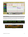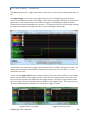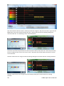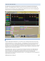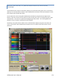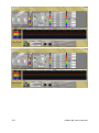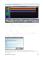
1
USBEE QX USERS MANUAL CWAV, Inc. www.usbee.com 2 USBee QX User’s Manual USBEE QX USERS MANUAL CWAV, Inc. www.usbee.com (951) 694-6808 [email protected] USBee QX User’s Manual 3 USBee QX Suite License Agreement The following License Agreement is a legal agreement between you (either an individual or entity), the end user, and CWAV, Inc. makers of the USBee Test Pods and USBee QX Suite software. You have received or downloaded the USBee QX Suite Package (“Software”), which consists of the USBee QX Suite Software and Documentation. If you do not agree to the terms of the agreement, do not install and run this software. By installing this USBee QX Suite software, you agree to be bound by the terms of this Agreement. Grant of License CWAV provides royalty-free Software, both in the USBee Package and on-line at www.usbee.com, for use with the USBee Test Pods and grants you license to use this Software under the following conditions: a) You may use the USBee Software only in conjunction with a USBee Test Pod, or in demonstration mode with no USBee Pod connected, b) You may not use this Software in conjunction with any pod providing similar functionality made by other than CWAV, Inc, and c) You may not sell, rent, transfer or lease the Software to another party. Copyright No part of the USBee Package (including but not limited to Software, manuals, labels, USBee Pod, or accompanying diskettes) may be reproduced, stored in a retrieval system, or transcribed, in any form or by any means, electronic, mechanical, photocopying, recording or otherwise, without the prior written permission of CWAV, Inc, with the sole exception of making backup copies of the Software for restoration purposes on your own machine. You may not reverse engineer, decompile, disassemble, merge or alter the USBee Software or USBee Pod in any way. Limited Warranty The USBee Software and related contents are provided “as is” without warranty of any kind, either expressed or implied, including but not limited to the implied warranties of merchantability and fitness for a particular purpose, with the sole exception of manufacturing failures in the USBee Pod or diskettes. CWAV warrants the USBee Pod and physical diskettes to be free from defects in materials and workmanship for a period of 12 (twelve) months from the purchase date. If during this period a defect in the above should occur, the defective item may be returned to the place of purchase for a replacement. After this period a nominal fee will be charged for replacement parts. You may, however, return the entire USBee Package within 30 days from the date of purchase for any reason for a full refund as long as the contents are in the same condition as when shipped to you. Damaged or incomplete USBee Packages will not be refunded. Software Updates The information in the Software and Documentation is subject to change without notice and, except for the warranty, does not represent a commitment on the part of CWAV. CWAV cannot be held liable for any mistakes in these items and reserves the right to make changes to the product in order to make improvements at any time. The Software will change from time to time to add new functionality, fix bugs and disable the use of non-CWAV made products that attempt to use this Software. Liability IN NO EVENT WILL CWAV BE LIABLE TO YOU FOR DAMAGES, DIRECT, INDIRECT, INCIDENTAL OR CONSEQUENTIAL, INCLUDING DAMAGES FOR ANY LOST PROFITS, LOST SAVINGS OR OTHER INCIDENTAL OR CONSEQUENTIAL DAMAGES, ARISING OUT OF THE USE OR INABILITY TO USE SUCH USBEE POD, SOFTWARE AND DOCUMENTATION, EVEN IF CWAV HAS BEEN ADVISED OF THE POSSIBILITY OF SUCH DAMAGES OR FOR ANY CLAIM BY ANY OTHER PARTY. SOME STATES DO NOT ALLOW THE EXCLUSION OR LIMITATION OF LIABILITY FOR CONSEQUENTIAL OR INCIDENTAL DAMAGES, SO THE ABOVE LIMITATION MAY NOT APPLY TO YOU. IN NO EVENT WILL CWAV’S LIABILITY FOR DAMAGES TO YOU OR ANY OTHER PERSON EVER EXCEED THE AMOUNT OF THE PURCHASE PRICE PAID BY YOU TO CWAV TO ACQUIRE THE USBEE, REGARDLESS OF THE FORM OF THE CLAIM. Term This license agreement is effective until terminated. You may terminate it at any time by returning the USBee Package (together with the USBee Pod, Software and Documentation) to CWAV. It will also terminate upon conditions set forth elsewhere in this agreement or if you fail to comply with any term or condition of this agreement. You agree that upon such termination you will return the USBee Package, together with the USBee Pod, Software and Documentation, to CWAV. USBee QX User’s Manual, Version 1.5 Copyright 2015 CWAV. All Rights Reserved 4 USBee QX User’s Manual CONTENTS INTRODUCING THE USBEE QX POD .................................................................. 12 THE USBEE QX TEST POD ........................................................................................ 14 PC SYSTEM REQUIREMENTS ...................................................................................... 16 EACH PACKAGE INCLUDES ......................................................................................... 16 INTRODUCING THE USBEE QX SUITE ................................................................ 18 USBEE QX SUITE OVERVIEW .................................................................................... 18 See the information you want FAST! .......................................................... 19 Data Acquisition over USB 3.0 .................................................................... 19 Superior Quality Design - Professional Results ........................................... 19 Fast and Detailed Waveform Viewing ........................................................ 19 Measure It .................................................................................................. 20 Fully configurable Look and Feel ................................................................ 20 Serial Bus Analysis ...................................................................................... 21 Data Storage ............................................................................................... 23 PacketPresenter.......................................................................................... 24 Fast Pan Bus Viewing .................................................................................. 25 Hot Keys ...................................................................................................... 26 Smart Search............................................................................................... 27 Sample and Smart Markers ........................................................................ 27 Annotations and Sticky Notes ..................................................................... 28 Acquisition Control ..................................................................................... 28 Display Modes ............................................................................................ 29 Analog Channels Scaling ............................................................................. 29 USBee Suite Data File Importing ................................................................. 29 Browser-like Navigation.............................................................................. 30 Complex Triggering ..................................................................................... 30 Relative Time Decode ................................................................................. 31 USBEE QX CONTROL PANEL ..................................................................................... 32 QUICK START ................................................................................................... 33 PC SYSTEM REQUIREMENTS ...................................................................................... 33 SOFTWARE INSTALLATION ......................................................................................... 34 Detailed Software Installation ........................................................................ 35 DEMO MODE ......................................................................................................... 39 TESTING YOUR CIRCUIT USING THE USBEE QX ............................................................. 40 USING THE USBEE QX SUITE MIXED SIGNAL OSCILLOSCOPE ............................. 41 ANALYZER SETUP .................................................................................................... 41 USBee QX User’s Manual 5 Quick Setup Configuration .............................................................................. 41 Hot Keys .......................................................................................................... 45 Signal Names .................................................................................................. 45 Buffer Sizes and Sample Rate settings ............................................................ 45 Setting Simple Triggers ................................................................................... 49 Setting Complex Triggers ................................................................................ 50 CAPTURING WAVEFORM DATA .................................................................................. 52 VIEWING CAPTURED DATA........................................................................................ 52 Scrolling, Zooming and Panning Waveforms .................................................. 52 Modifying Wave lines ..................................................................................... 54 Decoding Bus Traffic Inline .............................................................................. 56 Decoded Data List ........................................................................................... 59 Manual Measurements and Cursors ............................................................... 59 Insta-Measurements ....................................................................................... 60 BUS DECODING OPTIONS ......................................................................................... 62 Generic Signal Setup ....................................................................................... 62 CAN Bus Setup ................................................................................................. 64 USB Bus Setup ................................................................................................. 65 I2C Bus Setup .................................................................................................. 66 Async Bus Setup .............................................................................................. 67 Parallel Bus Setup ........................................................................................... 68 1-Wire Bus Setup ............................................................................................. 69 SPI Bus Setup ................................................................................................... 70 SDIO Bus Setup ................................................................................................ 71 SM Bus Bus Setup ............................................................................................ 73 Serial Bus Setup ............................................................................................... 74 I2S Bus Setup ................................................................................................... 75 PS/2 Bus Setup ................................................................................................ 76 SETTING VIEWING PREFERENCES ................................................................................ 77 Cursor Colors ................................................................................................... 77 Background Color ............................................................................................ 77 Glass Appearance ........................................................................................... 77 FILE OPERATIONS .................................................................................................... 78 Creating a New File ......................................................................................... 78 Saving a Capture File....................................................................................... 78 Open and Existing Capture File ....................................................................... 78 Recently Used File List ..................................................................................... 78 Exporting Captured Data to a File ................................................................... 78 Export Signal Data to Binary File ............................................................................... 80 6 USBee QX User’s Manual Export Signal Data to Text/CSV File .......................................................................... 80 Export Bus Data to Text/CSV File .............................................................................. 80 PRINTING .............................................................................................................. 81 CREATING SCREEN SHOTS ......................................................................................... 81 SOFTWARE UPDATES ............................................................................................... 82 DEVELOPING YOUR OWN CUSTOM DECODERS ............................................................. 83 Using the Custom Decoder .............................................................................. 83 Building the Custom Decoder .......................................................................... 85 Example Class Library Code............................................................................. 86 Custom Decoder Parameters .................................................................................... 92 Accessing Sample Data to Perform Decode .............................................................. 93 Outputting Entries that will get displayed on the Screen................................ 93 Sending Data and Events that will get displayed on the PacketPresenter ...... 94 Changing the Background Color of Outputted Entries .................................... 95 SMART SEARCH ...................................................................................................... 97 Adding a Search Line ....................................................................................... 97 Viewing Search Matches ................................................................................. 98 Entering a Smart Search ................................................................................. 99 Digital Signal Edges ................................................................................................. 100 Analog Signal Edges ................................................................................................ 101 Bus Data .................................................................................................................. 102 Digital Signal States and Ranges ............................................................................. 103 Analog Signal States and Ranges ............................................................................ 105 Time Window Qualifier ........................................................................................... 107 FAST PAN BUS VIEWING......................................................................................... 110 SAMPLE AND SMART MARKERS ............................................................................... 111 Sample Markers ............................................................................................ 111 SMart Markers .............................................................................................. 112 ANNOTATIONS AND STICKY NOTES ........................................................................... 113 Annotations................................................................................................... 114 Sticky Notes................................................................................................... 115 ACQUISITION CONTROL .......................................................................................... 116 DISPLAY MODES ................................................................................................... 117 ANALOG CHANNELS SCALING .................................................................................. 119 BROWSER-LIKE NAVIGATION ................................................................................... 120 RELATIVE TIME DECODE ......................................................................................... 121 PACKETPRESENTER™ ............................................................................................. 123 Overview ....................................................................................................... 123 Setting Up the PacketPresenter .................................................................... 126 Viewing the PacketPresenter Output ............................................................ 126 USBee QX User’s Manual 7 Saving PacketPresenter Data to Text or RTF Files ......................................... 127 Copying PacketPresenter Output to Other Programs ................................... 128 Searching For Packets ................................................................................... 129 Filtering Packets ............................................................................................ 130 PacketPresenter to Waveform Association using Cursors ............................ 131 PacketPresenter Definition File Format ........................................................ 132 Comments in the PacketPresenter Definition File .................................................. 132 Constants in the PacketPresenter Definition File ................................................... 132 PacketPresenter Definition File Sections ................................................................ 133 Protocol Section .................................................................................................. 133 Byte-wise busses vs. Bit-wise busses ............................................................... 133 Bus Events ........................................................................................................ 134 Data Channels and Multiple Data Signals ........................................................ 136 Packet Section ................................................................................................. 136 Start and End Sections .............................................................................. 137 type = Next ............................................................................................ 137 type = Signal .......................................................................................... 138 type = Value .......................................................................................... 138 type = Length......................................................................................... 138 type = Event .......................................................................................... 139 type = Timeout ...................................................................................... 139 CHANNELX, CHANNELY or CHANNELXorY ............................................. 140 Decode Section ......................................................................................... 140 Substitutions ......................................................................................... 141 Fields Section ................................................................................................... 141 Field Lines Processing ............................................................................... 141 Unconditional Field Lines ...................................................................... 142 Conditional Field Lines .......................................................................... 142 Field Line Format ...................................................................................... 142 Field Format .............................................................................................. 142 Bus Events in the middle of a packet ........................................................ 143 Lookup Tables ........................................................................................... 144 Examples of Field Lines and Fields ............................................................ 145 Just Plain Data ....................................................................................... 145 Conditional Packet Format .................................................................... 145 String Lookup ........................................................................................ 146 Conditional Route of data to another Protocol ............................................... 146 PacketPresenter Add-In API .......................................................................... 148 Sample PacketPresenter Add-In Decoders ............................................................. 149 Loopback Decoder............................................................................................... 149 Inverting Decoder ................................................................................................ 149 Expanding Decoder ............................................................................................. 149 8 USBee QX User’s Manual Compressing Decoder ......................................................................................... 150 Multiple Decoders ............................................................................................... 151 PacketPresenter Definition File Debugging ................................................... 151 PacketPresenter Specifications ..................................................................... 152 Example Protocol Files and Output Examples ............................................... 153 Async Protocol Example.......................................................................................... 153 I2C Protocol Example .............................................................................................. 154 SPI Protocol Example .............................................................................................. 155 CAN Protocol Example ............................................................................................ 157 SDIO Protocol Example ........................................................................................... 157 1-Wire Protocol Example ........................................................................................ 161 Parallel Protocol Example ....................................................................................... 162 Serial Protocol Example .......................................................................................... 163 USB Protocol Example ............................................................................................ 164 PS2 Protocol Example ............................................................................................. 166 USBEE QX ANALOG SIGNAL GENERATOR ....................................................... 167 USBEE QX LOGIC PROBE AND DIGITAL VOLTAGE METER ................................ 169 USBEE DIGITAL LOGIC THRESHOLD ................................................................. 170 USBEE QX DIGITAL SIGNAL GENERATOR ........................................................ 171 PULSE WIDTH MODULATORS .................................................................................. 171 ARBITRARY DIGITAL PATTERN GENERATOR................................................................. 173 Specifying the Pattern With a CSV File .......................................................... 173 Sample Clocking ............................................................................................ 174 Waveform Generation Control ...................................................................... 174 USBEE QX EDGE/PULSE COUNTERS ................................................................ 176 USBEE QX FREQUENCY COUNTERS ................................................................. 177 USBEE QX WIFI MODE .................................................................................... 178 WiFi Mode Setup ........................................................................................... 178 AUTOMATION ................................................................................................ 180 USBEE QX TOOLBUILDER ................................................................................ 182 OVERVIEW........................................................................................................... 182 System Software Architecture ....................................................................... 182 INSTALLING THE USBEE QX TOOLBUILDER ................................................................. 183 USBee QX Toolbuilder ProjectS ..................................................................... 183 USBEE QX TOOLBUILDER FUNCTIONS ....................................................................... 184 USBee QX User’s Manual 9 Initializing the USBee QX Pod ........................................................................ 184 InitializeQX .............................................................................................................. 184 SetLogicThresholdQX – Setting the Digital Logic Threshold.................................... 184 SetANALOGChannelSettings – Setting the Analog Channels .................................. 184 PowerOnAnalogQX – Turning On Power to the Analog Channels .......................... 185 PowerOffAnalogQX – Turning Off Power to the Analog Channels .......................... 185 AnalogLiveVoltage – Reading the Voltage on the Analog Channels ....................... 186 Reading and Setting Signal States ................................................................ 186 SetSignalsQX - Setting the USBee QX Output Signals ............................................. 186 GetDigitalSignalsQX - Reading the USBee QX Input Signals .................................... 187 GenerateAnalogWaveformQX – Controlling the AOUT signal ................................ 187 Logic Analyzer and Oscilloscope Functions ................................................... 188 StartCaptureQX ....................................................................................................... 188 CaptureStatusQX .................................................................................................... 189 StopCaptureQX ....................................................................................................... 189 TriggerNowQX ........................................................................................................ 189 EndCaptureQX ........................................................................................................ 190 SampleDigitalData .................................................................................................. 190 AnalogSampleVoltage ............................................................................................. 190 FindNextEdge .......................................................................................................... 191 SetTriggersQX ......................................................................................................... 191 DecodeUSB ............................................................................................................. 192 DecodeSPI ............................................................................................................... 194 DecodeI2C............................................................................................................... 195 DecodeCAN ............................................................................................................. 196 Decode1Wire .......................................................................................................... 197 DecodeParallel ........................................................................................................ 198 DecodeSerial ........................................................................................................... 199 DecodeASYNC ......................................................................................................... 200 DecodeSetName ..................................................................................................... 201 Digital Pattern Generator Functions ............................................................. 201 GeneratePWMWaveformQX .................................................................................. 201 LoadDigitalWaveformQX ........................................................................................ 202 GenerateDigitalWaveformQX ................................................................................. 202 Frequency and Pulse Counter Functions ....................................................... 203 ClearCountsQX ........................................................................................................ 203 EnableCountsQX ..................................................................................................... 203 DisableCountsQX .................................................................................................... 204 GetFrequencyAndCountsQX ................................................................................... 204 EXAMPLE C CODE ................................................................................................. 205 USBEE QX SUITE PRO MODULE ...................................................................... 211 10 USBee QX User’s Manual REGISTERING THE MODULE ..................................................................................... 211 SPECTRUM ANALYZER ............................................................................................ 212 PROTOCOL FIELD GRAPHING ................................................................................... 213 USBEE QX STREAMING MODULE .................................................................... 215 STREAMING BANDWIDTH ....................................................................................... 215 REGISTERING THE MODULE ..................................................................................... 216 USING DISK STREAMING......................................................................................... 216 VIEWING THE DISK STREAM .................................................................................... 218 EXTERNALLY PROCESSING THE DISK STREAM .............................................................. 218 7 Signal Capture Mode.................................................................................. 219 15 Signal Capture Mode................................................................................ 220 GETTING HELP ................................................................................................ 221 USBee QX User’s Manual 11 INTRODUCING THE USBEE QX POD The Tools You Need - All In One Place Introducing the Ultimate PC-Based Programmable Multifunction Mixed Signal Oscilloscope - Logic Analyzer with I2C, SPI, Async, SDIO, 1-Wire, CAN protocol decoders, Digital Signal Generators, Frequency Counter and integrated Protocol Analyzers in a compact and easy to use USB Test Pod. Designed to Solve Your Toughest Problems Using patented technology, the USBee QX has 4 analog and 24 digital channels, 100MHz to 600MHz sampling depending on channels used, 896 million sample internal buffers, Quad 10-bit ADC's, independent 100Msps 8 channel Digital Signal Generator, 7Msps Analog Signal Generator, +/- 60V protection on all inputs, Variable Logic Thresholds and USB over current protection. That's just the hardware. Mixed-Signal Multi-level Protocol Decoding Combined with the USBee QX Suite software, the USBee QX becomes a multi-layer protocol decoder for many of today's serial and parallel busses, letting you debug at the waveform, bus data, or packet level. In-Field Upgradable System Supports Addition of New Features Based on a proprietary design that allows the software, firmware and hardware to be dynamically reconfigured using web-based software downloads, the USBee QX and its ever growing list of Applications ensures that you will always have the most current tools available for years to come. With a single USB connection to your laptop or PC, the USBee QX gives you the power to design, prototype, test, and validate your mixed signal electronic designs with seamless ease. Built upon the popular, award-winning and patented USBee mixed signal Oscilloscope, Logic Analyzer, Signal 12 USBee QX User’s Manual Generator, and Protocol Analyzers, the USBee QX takes full advantage of the powerful debug capabilities of the USBee QX Suite software to solve your problems fast! The USBee QX Test Pod does not need an external power supply. The USB bus supplies the power to the pod, so your PC will be supplying the power. The Pod does, however, require a self powered hub (not bus powered) if a hub is used between the PC and Pod. The included power supply is required for WiFi use. USBee QX User’s Manual 13 THE USBEE QX TEST POD The USBee QX Test Pod has four sets of connectors: 14 USB o Connects to the PC via 6 foot USB cable (USB 3.0 or USB 2.0 compatible) CH1, CH2, CH3, CH4 o Analog Input Channels o BNC connectors for standard oscilloscope probes o +/- 60V tolerant o Sampled at up to 100MHz Digital Inputs Connector o 18 pins (9x2) – 2 Ground (G) and 16 Digital inputs (0-15) o 0.1” spaced 0.025” square header pins o +/-60V tolerant inputs o Connects to 1x2 pin Ground test lead set and 2 4x2 pin signal test lead sets o Sampled at up to 600MHz Digital Input/Outputs connector o 8 pins – 8 Digital Inputs or Outputs (16 – 21, plus T and C) o Mode is set from USBee QX Suite Control Panel o 0.1” spaced 0.025” square header pins o Digital Output pins are 0-2.5V logic with 600ohm series current limiting resistor o Outputs clocked at up to 100MHz o +/-6V tolerant inputs o Inputs sampled at up to 600MHz o Connects to 4x2 pin test lead set Analog Outputs connector o 3 pins – 1 Ground (GND), 1 Analog Aout, 1 +5V Supply o 0.1” spaced 0.025” square header pins o +5V output – actually VBus connected directly to the USB VBus signal from the PC through a resettable fuse, or from the included power supply o 1 Aout analog output pin used by the Analog Signal Generator function (0-3V levels) o Connects to single leads (Grey, Red, Green) USBee QX User’s Manual WARNING The USBee is galvanically isolated when connected via WiFi, but is NOT galvanically isolated when connected via USB. This mainly concerns systems where the target circuit AND the PC are plugged into AC power outlets. If your target system OR the PC (Laptop) are battery powered, there is no issue. If your PC and target circuit have different ground reference levels, connecting them together using the USBee GND signal can damage the devices. To ensure both your PC and target system share the same ground reference, do the following: 1. Use polarized power cords for both the PC and target and plug them into the same AC circuit. If you use non-polarized power cords or use separate power circuits, the PC and target system may have different ground references which can damage the USBee, target and/or PC. 2. Ensure that a GND signal on the USBee is connected to the target ground (and not another voltage level). 3. Or, use the USBee in WiFi connected mode. This gives a galvanically isolated setup. Also, As with all electronic equipment where you are working with live voltages, it is possible to hurt yourself or damage equipment if not used properly. Although we have designed the USBee QX pod for normal operating conditions, you can cause serious harm to humans and equipment by using the pod in conditions for which it is not specified. Specifically: ALWAYS connect at least one GND line to your circuits ground NEVER connect the digital signal lines (0 thru 21, T and C) to any voltage other than between -60 to +60 Volts NEVER connect the analog signal lines (CH1, CH2, CH3, CH4) to any voltage other than between -60 and +60 Volts The USBee QX actively drives Pod signals AOUT and 16 through 21 and T and C. Make sure that these pod test leads are either unconnected or connected to signals that are not also driving. There is a current limiting series resistor (680 ohm) in each of these lines in case of short. Plug in the USBee QX Pod into a powered PC BEFORE connecting the leads to your design. USBee QX User’s Manual 15 PC SYSTEM REQUIREMENTS The USBee QX Test Pod requires the following minimum PC features: Windows® XP, Vista, 7 or 8 32-bit or 64-bit operating system MAC OSX running VFusion or Parallels with one of the above Pentium or higher processor One USB 3.0 Super Speed or USB2.0 High Speed enabled port. It will not run on USB 1.1 Full Speed ports. 32MBytes of RAM 125MBytes of Hard disk space Internet Access (for software updates and technical support) 802.11 B/G Wireless network for WiFi operation EACH PACKAGE INCLUDES The USBee QX contains the following in each package: 16 USBee QX Test Pod 4 100MHz oscilloscope probes with x1 and x10 selection One 8 lead 9-inch signal generator cable set Two 8 lead 9-inch logic analyzer cable sets One 2 lead Ground cable set 3 lead 9-inch analog cable set 24 high performance micro grabber test clips 6 foot USB cable Power supply adapter USBee QX Suite Software (downloaded) USBee QX Suite Manuals (downloaded) USBee QX User’s Manual USBee QX User’s Manual 17 INTRODUCING THE USBEE QX SUITE The USBee QX Suite is powerful electronic signal analysis software for your USBee QX Test Pod. It starts out as an easy to use Logic Analyzer, Oscilloscope, Signal Generator, Frequency Counter and PWM Controller and adds serial bus decoding and world class configurability that lets you solve your electronic problems quickly! This chapter details the operation of the USBee QX Test Pod running the USBee QX Suite software. USBEE QX SUITE OVERVIEW The USBee QX Suite is a powerful mixed signal analyzer that on the USBee QX Test Pod. It is available for free from USBee.com and will run without restriction. The USBee QX Suite Standard will run in Demo mode without a USBee, or on any USBee QX Test Pod. It will not work on any other USBee test Pod model. 18 USBee QX User’s Manual USBee QX Control Panel Visible SEE THE INFORMATION YOU WANT FAST! Setup of the USBee QX Suite is fast! Capturing the data you need to solve your problems is just as fast. You can see your design in action with just one click thanks to the easy to use trigger settings, color coded signals and automatic buffer and sample rate settings. DATA ACQUISITION OVER USB 3.0 Capture from 100 to 600 million samples per second for sample buffer depths of up to 32 million samples or 16 million transitions. SUPERIOR QUALITY DESIGN - PROFESSIONAL RESULTS The USBee QX Suite takes full advantage of the power the USBee QX Test Pod. Each USBee QX comes with the best color coded highly flexible test leads, the best test clips and our signature small and sleek design that can fit right in your pocket. We are proud to say the entire USBee product line is designed and manufactured in the USA! FAST AND DETAILED WAVEFORM VIEWING The USBee QX Suite lets you capture a huge amount of data. Go exactly to the section of that data you want using the Quick Zoom with your mouse scroll wheel, or use the Overview bar to rip through your millions of samples or hone in on a specific section. USBee QX User’s Manual 19 MEASURE IT Should that pulse be 10ms? Measure it using our super easy edge snapping timing cursors. Better yet, you can use our Insta-Measure feature to instantly calculate the width, period, frequency and duty cycle of the waveform under the cursor. FULLY CONFIGURABLE LOOK AND FEEL View your signals like you like them. Want to add decoded bus traffic to the waveforms? Done! Want to delete waves from the screen? Done! Want to reorder waveforms for easier readability? Done! Want to resize the screen for easier reading or more data per screen? Done! And you like Magenta? Well you can change cursor colors to suite your desires. Waveform backgrounds can also be customized, and you can even give the entire application that cool Glassy look that Vista has made so popular. Then again, if you like simple, white and black are also available. It's good that white ink cartridges are free! 20 USBee QX User’s Manual USBee QX Suite showing SPI, I2C and Async decoding SERIAL BUS ANALYSIS USBee QX Suite has decoding support for your favorite serial busses such as I2C, SPI and Async. Bus traffic is decoded in-line with the waveforms and can be displayed on top of, underneath, or instead of the voltage versus time waveform. Just place the cursor over the decoded traffic and get a seethrough image that shows you the wiggles that made that byte! I2C Transaction USB Transaction USBee QX User’s Manual 21 Synchronous Serial Transaction PS2 Transaction Parallel Bus Decode I2S Decode CAN Transaction 22 USBee QX User’s Manual Serial Bus Setup is simple and straightforward - simply choose the signals for the bus and set how the bus is configured. Not sure how your design works? Not a problem. You can try different configuration settings and the busses will be decoded using those settings on the fly so you can get it right! (USBee SX options shown above) DATA STORAGE Save your entire data capture to file quickly using the USBee QX Suite data format to be read back in later for viewing. Or you can export your captured data to files that you can work with. Want to import your waveform data into Excel? No problem! Just export it as a comma separated file and it imports directly without modification. Need the data in raw binary format? We've got that too! USBee QX User’s Manual 23 PACKETPRESENTER The USBee QX Suite adds the PacketPresenter™ feature that runs alongside of the existing bus decoders. The PacketPresenter™ takes the output of raw binary data from the bus decoders and parses the stream according to users PacketPresenter Definition File for the intent of displaying the communications in easily understood graphical displays. 24 USBee QX User’s Manual FAST PAN BUS VIEWING The USBee QX Suite Fast Pan Bus Viewing lets you quickly pan through a busses decoded data. For each bus there is a left and right pan button on the left side of the screen. Simply press these buttons to page to the next or previous bus transactions. USBee QX User’s Manual 25 HOT KEYS The USBee QX has a full set of hot keys that lets you drive the acquisition of samples, setup configuration and quickly view your data using the keyboard. Key Function Left Arrow Right Arrow Shift-Left Arrow Shift-Right Arrow Up Arrow Down Arrow Home End Ins Del Space 1 2 A B D I O T Previous Edge/Packet Next Edge/Packet Pan Left Pan Right Previous Waveline Next Waveline Show the Start of capture buffer Show the end of the capture buffer Insert a new waveline below the current line Delete the current waveline Capture Once Go to the X1 cursor Go to the X2 cursor Zoom out to view all of the capture buffer Open the Waveline settings dialog box Toggle the Decoder List window Zoom In Zoom Out Go to the Trigger position 26 USBee QX User’s Manual SMART SEARCH USBee QX Suite Smart Search highlights the sections of your trace matching your areas of interest so that you don’t need to waste time hunting for the data you need. You can specify up to 32 levels of search events that are any combination of bus decoded traffic, states or edges of digital or analog signals, inside or outside of analog voltage ranges and/or digital ranges, and all validated by time specific windows. Once specified you can pan through the occurrences of your searched items with the click of the mouse and see the total number of times the searched events occur. SAMPLE AND SMART MARKERS Placing markers in your traces can help detail what is happening in your design. There are two types of markers that can be used. The first marker type locks itself to a sample on a waveform and lets you specify the text. The second is a Smart Marker that automatically measures the pulse width, frequency, period or duty cycle of the waveform at the marker location. USBee QX User’s Manual 27 ANNOTATIONS AND STICKY NOTES The USBee QX Suite adds Sticky Notes which you can use to further detail your traces for documentation purposes. You can also add Title and Footer text to your display that is saved with the trace file. ACQUISITION CONTROL The USBee QX Suite adds more trace acquisition and triggering controls such as Normal Mode, Automatic Mode, Single Capture and Multiple Capture. Normal mode will wait for the trigger event to occur before capturing. Automatic Mode will wait a set time for the trigger and will automatically trigger if it is not found. Single Capture mode performs a one-shot capture of the signals. Multiple Capture repeatedly captures and displays the signals. 28 USBee QX User’s Manual DISPLAY MODES The USBee QX Suite lets you widen the trace waveforms, display the analog waveforms as vectors or single sample points, and persist the display from one trace to the next. ANALOG CHANNELS SCALING The USBee QX Suite provides a scaling ability to convert the analog voltages into other units of measurement. USBEE SUITE DATA FILE IMPORTING USBee QX User’s Manual 29 The USBee QX, AX or ZX running the USBee Suite software saves files in their own file format. These older files can be imported into the USBee QX Suite. BROWSER-LIKE NAVIGATION The USBee QX Suite adds browser-like Forward and Back buttons that let you quickly navigate through your trace display. COMPLEX TRIGGERING The USBee QX Suite adds a multi-level hardware trigger to capture the events you need to see to solve your problems. 30 USBee QX User’s Manual RELATIVE TIME DECODE The USBee QX Suite also adds a Relative Time or Absolute Time setting for the decoded data lists. USBee QX User’s Manual 31 USBEE QX CONTROL PANEL The USBee QX Suite contains a Control Panel that controls many of the features of the USBee QX system, including the Variable Logic Threshold, Analog channel scaling, Current Logic and Analog levels, Analog Signal Generator, Digital Signal Generator, PWM controllers, Pulse Counters and Frequency Counters. 32 USBee QX User’s Manual QUICK START This section goes through installing the software for your USBee QX and getting you using the USBee QX quickly. PC SYSTEM REQUIREMENTS The USBee QX Suite requires the following minimum PC features: Windows® XP SP3, Vista or Windows 7/8 32-bit or 64-bit operating system .NET Framework 4.0 or greater. This is installed automatically during installation if not already on your PC. Pentium or higher processor One USB 3.0 High Speed enabled port. It will not run on USB 1.1 Full Speed ports. 32MBytes of RAM 125MBytes of Hard disk space Internet Access (for software updates and technical support) 802.11 B/G Wireless network for WiFi USBee QX User’s Manual 33 SOFTWARE INSTALLATION To ensure that you are using the latest version of USBee QX software, you can download the software from our web site at www.usbee.com. You must install the software on the PC before you plug in the USBee QX device. A quick guide to install the software follows: 34 Download the USBee QX Software from http://www.usbee.com/download.htm and open the usbeeQXsuitesw.zip file. Run the SETUP.EXE. Follow the instructions on the screen to install the USBee QX software on your hard drive. This may take several minutes. Now, plug the included USB A to USB Superspeed cable into the USBee QX and the other end into a free USB 3.0 High Speed port on your computer. You will see a dialog box indicating that it found new hardware and is installing the software for it. Follow the on screen directions to finish the driver install. The USBee QX Software is now installed. Run the USBee QX Suite software by going to the Start | Program Files |USBee QX Suite. If your PC does not already have .NET Frameworks version 4.0 or greater, you will be notified to download and install this from the Microsoft web site. USBee QX User’s Manual DETAILED SOFTWARE INSTALLATION The USBee QX Suite software is available for download from www.usbee.com/download.htm. It will run in a demonstration mode if you do not have a USBee QX Pod installed and attached. To install the USBee QX Suite software: Click the USBee QX Suite Software link at http://www.usbee.com/download.htm and click SAVE to save the software to a known directory. Open the ZIP file you just downloaded by clicking OPEN. If you receive messages such as below, press ALLOW or CONTINUE ANYWAY to continue with installation of the software. USBee QX User’s Manual 35 36 Run the SETUP.EXE file that is included in the ZIP file that you downloaded to start the installation. If you get the following warning, click RUN to continue with the installation. USBee QX User’s Manual The first part of the installation installs Microsoft requirements, including Microsoft .NET Frameworks Version 4.0. If you do not have this on your PC it will install it for you as shown below – click Accept to install the .NET Frameworks. This installation takes a LONG time, so please be patient since it is worth the wait! If you already have it installed, you will automatically see the “Welcome to the USBee QX Suite Setup Wizard” screen. You will see the Welcome to the USBee QX Suite Setup Wizard screen as shown below During the installation you will see a driver installation dialog box that will install the USBee QX drivers. Click Finish to complete the installation after the drivers have been successfully installed as below. USBee QX User’s Manual 37 38 Follow the instructions (clicking NEXT each time) on the screen to install the USBee QX Suite software on your hard drive. This may take several minutes. When completed you will see the following screen. Click CLOSE and the USBee QX Suite software is now installed. To run the USBee QX Suite software, choose the USBee QX Suite icon from the Windows Start Menu or click on the USBee QX icon on the desktop. If no USBee QX is plugged in or installed, you will see the following screen running in Demo Mode (see the top title bar). USBee QX User’s Manual If you have a USBee QX plugged in and installed correctly, you will see a screen with all available channels shown. Below is the USBee QX version showing 16 digital channels and 2 analog channels. You can also see that the device is connect (and not in demo mode) in the top title bar. DEMO MODE In the Demo mode, you can see an example trace capture by clicking the Demo button. This loads a trace that includes a number of serial busses and lets you see how the USBee QX Suite can decode the bus traffic, manipulate the waveform data, and use the features of the USBee QX Suite. The USBee QX Suite display shows the USBee connection status in the title bar of the application. If a USBee QX is connected to the computer when the application starts, the title bar indicates the connection status. If you run the software with no pod attached, it will run in demonstration mode and simulate data so that you can still see how the software functions. If you are running in Demo mode and you want to connect to your USBee QX pod, you must exit the USBee QX Suite, connect the USBee QX and then rerun the USBee QX Suite software. USBee QX User’s Manual 39 TESTING YOUR CIRCUIT USING THE USBEE QX In order to quickly get up and running using The USBee QX Suite application, here is a step by step list of the things you need to do to view a waveform trace, after you have installed the software and hardware. 40 Plug in the USBee QX Pod - Plug the USBee into your computer USB port. Connect Ground - Connect the GND wire to the Ground of your circuit you would like to test. You can either use the socket to plug onto a header post, or connect it to one of the mini-grabber clips and then attach it to the Ground. Connect Signals - Connect any of the USBee inputs on the USBee pod to your circuit you would like to test. You can either use the socket to plug onto a header post, or connect it to one of the mini-grabber clips and then attach it to your signal of choice. Run USBee QX Suite - Run the USBee QX Suite Application from the Start Menu. Press the Capture Once button - This will capture and display the current activity on all of the signals. View the Waveforms - You can then scroll the display, either by using the slider bars, or by clicking and dragging on the waveform itself. You can also change the knobs to zoom the waveform. Make Measurements - You can make simple measurements by using the Cursors area (gray bars under the waves). Click the left mouse button to place one cursor and click the right mouse button to place the second. The resulting measurements are then displayed in the Measurements section of the display. USBee QX User’s Manual USING THE USBEE QX SUITE MIXED SIGNAL OSCILLOSCOPE This section details the operation of the Mixed Signal Oscilloscope, Logic Analyzer and Protocol Analyzer features of the USBee QX Suite application that runs on the USBee QX Test Pod. When the USBee QX Suite is first run, you will see a screen containing all of the available input signals for the USBee QX Pod plugged into the PC. The USBee QX Suite maintains its last configuration and will reload that configuration when it is run again. This configuration is located in your \Users\NAME\AppData\Local\USBeeSuite directory where NAME is your username. To reset the software to the initial state you can delete the files in that directory. ANALYZER SETUP QUICK SETUP CONFIGURATION The USBee QX Suite can capture all of the input channels on the USBee QX. With a QX plugged in, it can capture 24 channels of digital (22 data lines, Clock and Trigger signals) and 4 channels of analog at the same time. Although you can individually show each signal, there are a number of Quick Configurations that let you instantly select just the channels you need. To select a configuration, click Setup on the menu and select the Quick Setup configuration of your choice. Below shows the available Quick Setup options for the USBee QX. USBee QX User’s Manual 41 You can also select these modes using the buttons at the bottom of the screen: The FAST button sets the Sample Rate and buffer size to give the fastest screen update rates. Below are examples of the application in various modes. 16 Digital–2 Analog Channels 42 8 Digital–0 Analog Channels USBee QX User’s Manual 8 Digital–1 Analog Channels 0 Digital–2 Analog Channels There are also three other Quick Setup features that let you instantly setup an I2C, SPI or ASYNC decoder line. The Quick Setup – SPI configures the first 4 lines to be an SPI bus with the SS, SCK, MOSI and MISO lines. It also adds a decoder line to the screen with this data decoded as below. The Quick Setup – I2C configures the signals 4 and 5 to be an I2C bus with the SDA and SCL lines. It also adds a decoder line to the screen with this data decoded as below. USBee QX User’s Manual 43 The Quick Setup – ASYNC configures the signals 6 and 7 to be a full duplex ASYNC bus with the TX and QX lines. You will need to change the baud rate, data bits and parity to match your bus. It also adds a decoder line to the screen with this data decoded as below. 44 USBee QX User’s Manual HOT KEYS The USBee QX has a full set of hot keys that lets you drive the acquisition of samples, setup configuration and quickly view your data using the keyboard. Key Function Left Arrow Right Arrow Shift-Left Arrow Shift-Right Arrow Up Arrow Down Arrow Home End Ins Del Space 1 2 A B D I O T Previous Edge/Packet Next Edge/Packet Pan Left Pan Right Previous Waveline Next Waveline Show the Start of capture buffer Show the end of the capture buffer Insert a new waveline below the current line Delete the current waveline Capture Once Go to the X1 cursor Go to the X2 cursor Zoom out to view all of the capture buffer Open the Waveline settings dialog box Toggle the Decoder List window Zoom In Zoom Out Go to the Trigger position SIGNAL NAMES To change the names shown for a signal, click on the signal name and enter a new name. BUFFER SIZES AND SAM PLE RATE SETTINGS The USBEE QX SUITE captures the behavior of the digital and analog signals and displays them as “traces” in the waveform window. The Speed and Samples menu lets you choose how the traces are captured. Below shows the Speed and Samples menu. USBee QX User’s Manual 45 The Buffer Size lets you select the size of the Sample Buffer that is used. For each trace, the buffer is completely filled, and then the waveform is displayed. You can choose buffers that will capture the information that you want to see, but remember that the larger the buffer, the longer it will take to fill, display and decode. 46 USBee QX User’s Manual You can also choose the Sample Rate that you want samples taken. You can choose from 100ksps (samples per second) to up to 600 Msps. At up to 100Msps all channels can be sampled. At higher sample rates, a subset of channels is available. The table below shows how many channels are available for the given sample rates. Available Channels and resulting Sample Rate for each channel Sample Rate Setting in sps < = 100M (1) 200M (2) 300M (3) 600M (6) CH4 CH3 CH2 CH1 0 1 2 3 4 5 6 7 8 9 10 11 12 13 14 15 16 17 18 19 20 21 T C 1 1 1 1 1 1 1 1 1 1 1 1 1 1 1 1 1 1 1 1 1 1 1 1 1 1 1 1 1 1 1 1 2 2 2 2 2 2 2 2 x x x x x x x x 1 1 1 1 1 1 1 1 1 1 1 1 3 3 3 3 3 1 1 1 1 6 6 1 1 1 1 x x x x x x x x x x 1 1 1 1 1 1 1 1 USBee QX User’s Manual 1 x x x x x x x x x x 1 1 1 1 1 1 1 1 47 The USBee QX can use sample compression to lengthen the capture time. In Sample Compression mode, only the transitions are stored, effectively removing the samples between inactivity. To turn on Sample Compression, select Sample Compression On in the Speed and Samples menu. The Sample Compression works on just the channels that are shown on the screen, so for the longest trace buffers, only display the signals that you are interested in. All other channels will be masked out and not captured. You can also use an external clock (using the C input) to gather each sample instead of the internal sample clock. To turn on External Clocking, select External Clocking using the C Input on the Speed and Samples menu. The external clock can run up to 100MHz. When external Clocking is enabled, Sample Compression is not available. 48 USBee QX User’s Manual SETTING SIMPLE TRIGGERS The USBee QX Suite uses a Trigger mechanism to allow you to capture just the data that you want to see. For a Digital trigger, you can specify the digital states for any of the digital signals that must be present on the digital lines before it will trigger. Below shows the trigger settings (to the right of the Signal labels). This example shows that we want to trigger on a falling edge of Signal 0, which is represented by a high level followed by a low level. To change the level of any of the trigger settings, just click the level button to change from don’t care to rising edge to falling edge. The waveforms are shown with a trigger position which represents where the trigger occurred. This sample point is marked on the waveform display with a Vertical red cursor line and a “T” in the horizontal cursors bar. You can use the Trigger Position menu setting to specify how much of the data that is in the sample buffer comes before the actual trigger position. If you place the Trigger Position all the way to the left, most of the samples taken will be after the trigger sample. If you place Trigger Position all the way to the right, most of the samples taken will be before the Trigger sample. This control lets you see what actually happened way before or way after the trigger occurred. Trigger Position to the Right USBee QX User’s Manual Trigger Position to the Left 49 For an Analog trigger you must specify the Channel to use, Rising or Falling Edge, and the Trigger Level. Click on the Trigger Settings Box (to the right of the waveline delete “X”) repeatedly to toggle through Channel 1 Rising, Channel 1 Falling, Channel 2 Rising, Channel 2 Falling, etc, and None. You then specify the trigger voltage level (-6V to +6V) by using the vertical slider on the left hand side of the analog waveform display. The trigger level edge and value will be shown as you scroll this level underneath the Volts/Div and Secs/Div labels within the waveform area. For an analog trigger, the trigger position is where the waveform crossed the Trigger Voltage level that you have set at the specified slope. To move the trigger voltage level, just move the slider on the left of the waveform. The following figures show a trace captured on each of the edges. Analog Trigger Slope = Rising Edge Analog Trigger Slope = Falling Edge The Trigger position is placed where the actual signal crosses the trigger voltage with the proper slope. The USBee pods allow for huge sample buffers, which means that you can capture much more data than can be shown on a single screen. Therefore you can scroll the waveform back and forth on the display to see what happened before or after the trigger. SETTING COMPLEX TRIGGERS The USBee QX Suite also allows you to set more complex triggers using the Triggers Dialog box as shown below. 50 USBee QX User’s Manual There are two levels of triggers available, X and Y. Each trigger event (X or Y) can have any combination of analog or digital edges which can be qualified using digital patterns or analog voltage levels. USBee QX User’s Manual 51 CAPTURING WAVEFORM DATA Press the Capture buttons to start capturing the waveform data from your hardware design. If you are running in Demo mode, the button reads Demo. Capture Once performs a single capture, while Capture Many repeatedly captures and displays consecutive traces. Each capture will look for the trigger condition, fill the buffer with samples of the signals and stop. If you would like to stop the capture before it is completed just press the same button again (which reads STOP during a capture). After a trace is captured, the waveform data is gathered, decoded (if needed) and displayed in the waveform window. VIEWING CAPTURED DATA SCROLLING, ZOOMING AND PANNING WAVEFORMS The Waveform display area is where the measured signal information is shown. It is displayed with time increasing from left to right and voltage increasing from bottom to top. 52 USBee QX User’s Manual The position of the waveform defaults to show the actual trigger position in the center of the screen after a capture. However, you can move the display to see what happened before or after the trigger position. To Scroll the Waveforms in Time left and right, you can click on the overview bar above the knobs, scroll the Pan knob (click and drag or mouse wheel on the knob) or you can simply click and drag the waveform itself with the left mouse button. To Scroll the Analog Waveform in Voltage up and down, you can simply click and drag the waveform itself by selecting and dragging using the mouse or use the analog offset knob to the left of the analog waveforms. To Zoom In or Zoom Out, or otherwise change the number of Seconds per Division, you can use the scroll wheel or single click on the waveform. You can also use the Zoom knob (click and drag or mouse wheel on the knob). To zoom in, scroll up or click the left mouse on the waveform window. To zoom out in time, scroll down or click the right mouse button on the waveform window. To change the number of Volts per Division for an analog channel, use the V/div knob (click and drag or mouse wheel on the knob) highlight the channel you want to change, or you can hold the left mouse button down and use the scroll wheel. You can also highlight the signal and use the slider bar to the left of the waveform. To view the entire capture buffer on the display, press the All button. The screen below shows all of the collected samples on a single screen for that trace. USBee QX User’s Manual 53 To Stretch and Shrink the display, you can click and drag the edges of the application to the size you want. All waves will scale to fit. Below you see two examples of different size displays. MODIFYING WAVE LINES Each line on the display is called a Waveline. Wavelines can be modified to your liking so that you see the data you need to solve your problem. You can delete, add, move, or reconfigure any waveline. To Delete a Waveline from the screen, press the little X near the signal name. This will remove the waveline from the screen. Below shows the USBee QX Suite after deleting the Digital 2 waveline. 54 USBee QX User’s Manual To Move a Waveline, simply click on the gray tab on the left and drag it to the new position. Below shows the Digital 0 signal moved to the bottom. To Add a Waveline, click on the small + sign above where you want to insert the new waveline. Below you see a new waveline inserted after the first waveline. When you insert a new waveline the Channel Selection dialog box appears for you to choose the settings for that waveline. Below shows the Channel Settings Dialog Box. Once you select the properties of the new waveline, it will be displayed with the other signals. Below shows a new line added that shows the Digital 2 single signal. USBee QX User’s Manual 55 We will go through creating Bus wavelines that decode bus traffic in-line in the next section. To Modify an Existing Waveline click on the grey tab on the left of the waveline. This will bring up the Channel Settings dialog box and allow you to change the settings for that line. Below we modified the last line to show Digital 2 signal instead of the Digital 0 signal. DECODING BUS TRAFFIC INLINE The USBee QX Suite software can decode certain types of serial busses automatically and display that information in-line with the waveforms. Below is an example of a screen that shows 3 different serial bus decoders at the same time, one SPI, one I2C, and one full duplex ASYNC channel. 56 USBee QX User’s Manual We will go through an example that shows how to setup various busses. We start with a capture of 8 digital lines that have a number of busses included. In this example, we will name the bus signals first to make it easier to reference. USBee QX User’s Manual 57 Now we will add an SPI bus which is made up of the first 4 signals. We press the small + sign near the MISO label to insert the waveline below that line. We then get the Channel Settings Dialog and choose the SPI tab. The following screen is then displayed. From here we select the parameters for this bus (shown above) and press Save. Once we press Save, the line is added to the screen, the current trace is decoded, and the decoded information is shown on the waveline. We then add the I2C bus using the Channel Settings dialog box as below with the resulting waveline. We then add the Async bus using the Channel Settings dialog box as below with the resulting waveline. 58 USBee QX User’s Manual Each bus type has various parameters that can be tailored to get the data out of your bus the way you need it. DECODED DATA LIST You can see the decoded list data in vertical format using the View/Show Decode Bus Listing menu item. This opens a window on the right side of the screen that displays the decoded data in vertical format. The data shown is the data that is decoded from the left side of the waveform screen. This data is synchronized to the waveforms as you pan and zoom. You can hide or change the width of the Decoded Bus Listing window by clicking and dragging the vertical line to the left of the window. MANUAL MEASUREMENTS AND CURSORS The main reason for using an oscilloscope or logic analyzer is to measure the various parts of a waveform. The USBee QX Suite uses cursors to help in these measurements. USBee QX User’s Manual 59 The X1 and X2 Cursors are placed on any horizontal sample time. This lets you measure the time at a specific location or the time between the two cursors. To place the X cursors, move the mouse to the gray Cursors box just below the waveform. When you move the mouse in this window, you will see a temporary line that indicates where the cursors will be placed. Place the X1 cursor by left clicking the mouse at the current location. Place the X2 cursor by right clicking the mouse at the current location. These cursors will snap to the exact edge of a digital signal when the mouse moves close to the edge. This lets you easily get exact measurements between edges of signals. In the Measurement window, you will see the various measurements made off of these cursors. X1 Position – time at the X1 cursor relative to the trigger position X2 Position – time at the X2 cursor relative to the trigger position QX – time difference between X1 and X2 cursors 1/QX – the frequency computed using the period between X1 and X2 cursors INSTA-MEASUREMENTS The Insta-Measure feature lets you quickly and accurately measure events and levels by simply hovering the mouse over a signal and without placing cursors. Inta-Measurements available are as follows: Analog Insta-Measurements Voltage At Cursor Digital Insta-Measurements Width, Period, Frequency and Duty Cycle 60 USBee QX User’s Manual Screen Shots? USBee QX User’s Manual 61 BUS DECODING OPTIONS The USBee QX Suite software has a powerful embedded bus decoder feature that allows you to quickly analyze the contents of embedded communications captured by the pod. This section details each of the available bus types and the parameters required for proper setup. GENERIC SIGNAL SETUP The default trace shown on a waveline is a voltage versus time waveform representation of an input wire on the USBee QX. Hardware Setup To use the generic signal display you need to connect the USBee Test Pod to your hardware using the test leads. You can either connect the test leads directly to pin headers on your board, or use the test clips for attaching to your components. Software Setup Activate the below Channel Settings Dialog by clicking the grey tab on the left of the signal names on the main application screen. On the above dialog box, select the signals you want to display by checking the associated check box, choose whether to show the value of the selected signals and what format you would like the values. The signal traffic will be shown as in the following screen. The SS line shows a single signal with the values turned on. The MOSI line shows a combination of three different signals and the resulting value of those signals. The associated settings dialog box is shown. 62 USBee QX User’s Manual USBee QX User’s Manual 63 CAN BUS SETUP The CAN Bus Decoder takes the captured data from a CAN bus (11 or 29-bit identifier supported), formats it and allows you to save the data to disk or export it to another application using Cut and Paste. Hardware Setup To use the Decoder you need to connect the USBee Test Pod to your hardware using the test leads. You can either connect the test leads directly to pin headers on your board, or use the test clips for attaching to your components. The CAN Bus Decoder connects to the digital side of your CAN bus transceiver and only needs to listen to the receiving side of the transceiver (such as the QXD pin on the Microchip MCP2551 CAN bus transceiver chip). Use signal 0 as the QXD data line and connect the GND line to the digital ground of your system. Connect these signals to the CAN bus transceiver IC using the test clips provided. Software Setup Activate the below Channel Settings Dialog by clicking the grey tab on the left of the signal names on the main application screen. On the above dialog box, select the CAN data signal, what speed the bus is operating at and what filter value for the ID you want (if any) The bus traffic will be decoded as in the following screen. 64 USBee QX User’s Manual USB BUS SETUP The USB Bus Decoder decodes Low and Full Speed USB. It does NOT decode High Speed USB Hardware Setup To use the Decoder you need to connect the USBee Test Pod to your hardware using the test leads. You can either connect the test leads directly to pin headers on your board, or use the test clips for attaching to your components. Connect two of the digital signals to the D+ and D- of your embedded USB bus, preferably at the IC of the USB device or the connector that the USB cable plugs into. Software Setup Activate the below Channel Settings Dialog by clicking the grey tab on the left of the signal names on the main application screen. On the above dialog box, select the D+ and D- signals and what speed the bus is operating at. You can also specify a specific USB Address or Endpoint you want to see. All other transactions will be filtered out. Leave the fields blank to see all transactions. The bus traffic will be decoded as in the following screen. USBee QX User’s Manual 65 I2C BUS SETUP The I2C Bus Decoder takes the captured data from an I2C bus. Hardware Setup To use the Decoder you need to connect the USBee Test Pod to your hardware using the test leads. You can either connect the test leads directly to pin headers on your board, or use the test clips for attaching to your components. The I2C Bus Decoder connects to the SDA and SCL lines of the I2C bus. Use one signal as the SDA data line and one signal as the SCL clock line. Also connect the GND line to the digital ground of your system. Connect these signals to the I2C bus using the test clips provided. Software Setup Activate the below Channel Settings Dialog by clicking the grey tab on the left of the signal names on the main application screen. On the above dialog box, select the SDA and SCL signals. The bus traffic will be decoded as in the following screen. 66 USBee QX User’s Manual ASYNC BUS SETUP The Async Bus Decoder takes the captured data from an asynchronous bus (UART). Hardware Setup To use the Decoder you need to connect the USBee Test Pod to your hardware using the test leads. You can either connect the test leads directly to pin headers on your board, or use the test clips for attaching to your components. The Async Bus Data decoder uses one or more of the 24 digital signal lines (0 thru 21 + T and C) and the GND (ground) line. Connect any of the 24 signal lines to an Async data bus. Connect the GND line to the digital ground of your system. Software Setup Activate the below Channel Settings Dialog by clicking the grey tab on the left of the signal names on the main application screen. On the above dialog box, select the channels you want to observe. Each channel can be attached to a different async channel. Also enter the baud rate (from 1 to 24000000), the number of data and parity bits, and what output format you want the traffic. USBee QX User’s Manual 67 PARALLEL BUS SETUP The Parallel Bus Decoder takes the captured data from a parallel bus. The Parallel Bus decoder is also a way to capture the data using an external clock. Hardware Setup To use the Decoder you need to connect the USBee Test Pod to your hardware using the test leads. You can either connect the test leads directly to pin headers on your board, or use the test clips for attaching to your components. The Parallel Bus Data decoder uses the 24 digital signal lines (0 thru 21 + T and C), the GND (ground) line. Connect the GND line to the digital ground of your system. Software Setup Activate the below Channel Settings Dialog by clicking the white box on the left of the signal names on the main application screen. On the above dialog box, select the channels you want to include in the parallel data bus. You can also use any one of the 16 digital signals as an external clock. Choose if you want to use the external clock signal and the external clock edge polarity. The bus traffic will be decoded as in the following screen. 68 USBee QX User’s Manual 1-WIRE BUS SETUP The 1-Wire Bus Decoder takes the captured data from a 1-Wire bus. Hardware Setup To use the Decoder you need to connect the USBee Test Pod to your hardware using the test leads. You can either connect the test leads directly to pin headers on your board, or use the test clips for attaching to your components. The 1-Wire Bus Data decoder uses any one of the 24 digital signal lines (0 thru 21 + T and C), the GND (ground) line. Connect the GND line to the digital ground of your system. Software Setup Activate the below Channel Settings Dialog by clicking the grey tab on the left of the signal names on the main application screen. On the above dialog box, select the signal running your 1-Wire protocol. USBee QX User’s Manual 69 SPI BUS SETUP The SPI Bus Decoder takes the captured data from an SPI bus. Hardware Setup To use the Decoder you need to connect the USBee Test Pod to your hardware using the test leads. You can either connect the test leads directly to pin headers on your board, or use the test clips for attaching to your components. The SPI Bus Decoder uses any one of the 24 digital signal lines (0 thru 21 + T and C) for the SS (slave select), SCK (clock), MISO (data in), MOSI (data out), and the GND (ground) line. Connect the SS, SCK, MISO, and MOSI to your digital bus using the test leads and clips. Connect the GND line to the digital ground of your system. Software Setup Activate the below Channel Settings Dialog by clicking the grey tab on the left of the signal names on the main application screen. On the above dialog box, select the signals you plan to use for the SPI protocol. Also set the appropriate sampling edges for both data lines and if you would like to use the SS (slave select) signal. If you turn off the SS, all clocks are considered valid data bits starting at the first clock detected. Also choose what output format you want the traffic. The bus traffic will be decoded as in the following screen. 70 USBee QX User’s Manual SDIO BUS SETUP The SDIO Bus Decoder shows the captured data from an SDIO bus Command and Data lines. Hardware Setup To use the Decoder you need to connect the USBee Test Pod to your hardware using the test leads. You can either connect the test leads directly to pin headers on your board, or use the test clips for attaching to your components. The SDIO Bus Decoder uses any one of the 24 digital signal lines (0 thru 21 + T and C) for the CMD (command), CLK (clock), DAT0, DAT1, DAT2, DAT3 and the GND (ground) line. Connect the CMD, CLK and DAT0-DAT3 lines to your digital bus using the test leads and clips. Connect the GND line to the digital ground of your system. Software Setup You will want to make sure that the sample rate you have chosen is at least 4 times the CLK frequency in order to recover the bus data reliably. So, for a CLK with a frequency of 50MHz, you need at least a sample rate of 200Msps. Also remember that at sample rates above 100Msps the available channels is reduced. Activate the below Channel Settings Dialog by clicking the grey tab on the left of the signal names on the main application screen. On the above dialog box, select the signals you plan to use for the SDIO protocol. Also set the appropriate sampling edge for the CMD and DAT lines, how many DAT lines to use and the size of the data blocks. Also choose the output format for the traffic. USBee QX User’s Manual 71 72 USBee QX User’s Manual SM BUS BUS SETUP The SM Bus Decoder takes the captured data from an SM bus. Hardware Setup To use the Decoder you need to connect the USBee Test Pod to your hardware using the test leads. You can either connect the test leads directly to pin headers on your board, or use the test clips for attaching to your components. The SM Bus Decoder uses any one of the 24 digital signal lines (0 thru 21 + T and C) for the SM Clock and SM Data, and the GND (ground) line. Connect the SM Clock and SM Data to your digital bus using the test leads and clips. Connect the GND line to the digital ground of your system. Software Setup Activate the below Channel Settings Dialog by clicking the white box on the left of the signal names on the main application screen. On the above dialog box, select the signals you plan to use for the SM Bus protocol. The bus traffic will be decoded as in the following screen. USBee QX User’s Manual 73 SERIAL BUS SETUP The Serial Bus Decoder takes the captured data from a Serial bus. The serial data can be from any clocked serial bus and can be aligned using a hardware signal or an embedded sync word. Hardware Setup To use the Decoder you need to connect the USBee Test Pod to your hardware using the test leads. You can either connect the test leads directly to pin headers on your board, or use the test clips for attaching to your components. The Serial Bus Decoder uses any one of the 24 digital signal lines (0 thru 21 + T and C) for the Clock, Data and optional Word Align signal, and the GND (ground) line. Connect the Clock, Data and Word Align to your digital bus using the test leads and clips. Connect the GND line to the digital ground of your system. Software Setup Activate the below Channel Settings Dialog by clicking the white box on the left of the signal names on the main application screen. On the above dialog box, select the signals you plan to use for the Serial Bus protocol. Select whether you have an external word align signal (Align Mode = Signal) or if your serial data has an embedded sync word in the data stream (Align Mode = Value). The Bits/Word is the size of the Sync word as well as the output word size. Choose the bit ordering as well as the output format of the traffic. The bus traffic will be decoded as in the following screen. 74 USBee QX User’s Manual I2S BUS SETUP The I2S Bus Decoder takes the captured data from an I2S bus. Hardware Setup To use the Decoder you need to connect the USBee Test Pod to your hardware using the test leads. You can either connect the test leads directly to pin headers on your board, or use the test clips for attaching to your components. The I2S Bus Decoder uses any one of the 24 digital signal lines (0 thru 21 + T and C) for the Clock, Data and Word Align signal, and the GND (ground) line. Connect the Clock, Data and Word Align to your digital bus using the test leads and clips. Connect the GND line to the digital ground of your system. Software Setup Activate the below Channel Settings Dialog by clicking the grey tab on the left of the signal names on the main application screen. On the above dialog box, select the signals you plan to use for the I2S Bus protocol. Select the start edge for the external word align signal, the Bits/Word and the Clock sampling edge. Choose the bit ordering. The bus traffic will be decoded as in the following screen. USBee QX User’s Manual 75 PS/2 BUS SETUP The PS/2 Bus Decoder takes the captured data from a PS/2 bus. Hardware Setup To use the Decoder you need to connect the USBee Test Pod to your hardware using the test leads. You can either connect the test leads directly to pin headers on your board, or use the test clips for attaching to your components. The PS/2 Bus Decoder uses any one of the 24 digital signal lines (0 thru 21 + T and C) for the Clock and Data signals, and the GND (ground) line. Connect the Clock and Data to your PS/2 bus using the test leads and clips. Connect the GND line to the digital ground of your system. Software Setup Activate the below Channel Settings Dialog by clicking the grey tab on the left of the signal names on the main application screen. On the above dialog box, select the signals you plan to use for the PS/2 Bus protocol. The bus traffic will be decoded as in the following screen. 76 USBee QX User’s Manual SETTING VIEWING PREFERENCES The USBee QX Suite has many ways that you can customize the display of your data, beyond the placement of the waveforms. CURSOR COLORS You can change the color of the Trigger, X1 and X2 cursors using the View Menu. When chosen you will see the Color Selection dialog box below. To change the colors back to their original state, use the View/Reset Colors to Default menu item. BACKGROUND COLOR The background of the waveform screen can be set to white or black using the View | Background White or View | Background Black menu items. GLASS APPEARANCE Windows has added the ability to have a Glassy appearance on applications. If your system is capable of this glassy look you can use the View/Show Glass If Possible menu item to turn it on. If it is not possible, or you turn off Glass, the display shows a grey background. With Glass On USBee QX User’s Manual With Glass Off 77 FILE OPERATIONS Using the File menu you can start a New file, Save trace data, Open previously saved traces and Export trace data to other file formats. CREATING A NEW FILE To start a new file, choose File/New. This will configure the screen to the default state with all available channels enabled. SAVING A CAPTURE FIL E After capturing a trace, you can save it to disk using the File/Save As menu item. This saves all trace data, cursor positions and screen format. The files can be saved in either Uncompressed format (.usbeesuite extension) or in Compressed format (.usbeecomp extension) to reduce drive space requirements. Saving and Opening large buffer sizes can take a while to perform the compression and saving but can greatly reduce disk space. OPEN AND EXISTING CAPTURE FILE To view a previously saved capture file, us the File/Open menu item. This will load the trace data and screen format including decoder setup. Opening files with large buffer sizes can take a while to decompress and display. RECENTLY USED FILE LIST The USBee QX Suite maintains a recently used file list that allows you to quickly load any of the last 5 previously used files. Simply click on the file name in the File, Recently Used file list to open it. EXPORTING CAPTURED DATA TO A FILE Since the compressed trace files are not in easily useable format, you can use the File/Export menu items to save the trace and decoded data into formats that are easy to use. 78 USBee QX User’s Manual The available options for exporting are: Save the Signal Data to a Binary File Save the Signal Data to a Text/CSV File Save the Bus Data to a Text/CSV file You can specify the range of samples to export by using the All, X1 to X2, or Screen versions. Screen will output all samples viewed on the current screen, X1 to X2 will output all samples between the X1 and X2 cursor, and All will output all samples in the sample buffer. Choosing All will create VERY large files, so use with caution. USBee QX User’s Manual 79 EXPORT SIGNAL DATA TO BINARY FILE When exporting signal data to a binary file, each sample is made up of 8 bytes. Each sample was taken at the sample rate that was set at the time of capture. A single sample (8 bytes) is formatted as follows: Byte 1 2 3 4 5 6 7 8 Description Digital channels 0 to 7 (lsb= signal 0, msb = signal 7) Digital channels 8 to 15 (lsb= signal 8, msb = signal 15) Channel 1 Analog voltage (0=-6V, 128 = 0V, 255 = +6V) Channel 2 Analog voltage (0=-6V, 128 = 0V, 255 = +6V) Digital channels 16 to C (lsb= signal 16, msb = signal C) Channel 3 Analog voltage (0=-6V, 128 = 0V, 255 = +6V) Channel 4 Analog voltage (0=-6V, 128 = 0V, 255 = +6V) Reserved EXPORT SIGNAL DATA TO TEXT/CSV FILE When exporting signal data to a text/csv file, each sample is output to a single line with each signal separated by a comma. Each sample was taken at the sample rate that was set at the time of capture. An example output file is formatted as follows showing a header that specifies the column labels and which signal is associated: Time,0,1,2,3,4,5,6,7,8,9,10,11,12,13,14,15,16,17,18,19,20,21,T,C,CH1,CH2,CH3,CH4 0.008739333,1,1,1,0,1,1,1,1,1,1,1,1,1,1,1,1,0,0,0,0,0,0,0,0,1.02,2.56,0.01,0.01 0.008739500,1,1,1,0,1,1,1,1,1,1,1,1,1,1,1,1,0,0,0,0,0,0,0,0,1.02,2.56,0.01,0.01 0.008739667,1,1,1,0,1,1,1,1,1,1,1,1,1,1,1,1,0,0,0,0,0,0,0,0,1.02,2.56,0.01,0.01 0.008739833,1,1,1,0,1,1,1,1,1,1,1,1,1,1,1,1,0,0,0,0,0,0,0,0,1.02,2.56,0.01,0.01 0.008740000,1,1,1,0,1,1,1,1,1,1,1,1,1,1,1,1,0,0,0,0,0,0,0,0,1.02,2.56,0.01,0.01 0.008740167,1,1,1,0,1,1,1,1,1,1,1,1,1,1,1,1,0,0,0,0,0,0,0,0,1.02,2.56,0.01,0.01 0.008740333,1,1,1,0,1,1,1,1,1,1,1,1,1,1,1,1,0,0,0,0,0,0,0,0,1.02,2.56,0.01,0.01 0.008740500,1,1,1,0,1,1,1,1,1,1,1,1,1,1,1,1,0,0,0,0,0,0,0,0,1.02,2.56,0.01,0.01 0.008740667,1,1,1,0,1,1,1,1,1,1,1,1,1,1,1,1,0,0,0,0,0,0,0,0,1.02,2.56,0.01,0.01 0.008740833,1,1,1,0,1,1,1,1,1,1,1,1,1,1,1,1,0,0,0,0,0,0,0,0,1.02,2.56,0.01,0.01 EXPORT BUS DATA TO TEXT/CSV FILE 80 USBee QX User’s Manual When exporting bus data to a text/csv file, each decoded element is output to a single line with each field separated by a comma. An example output file is formatted as follows showing a header that specifies the column labels and which signal is associated: Time(seconds),Bus Name, Signal Name, Data 0.000007167,SPI 3,MOSI,FF 0.000007167,SPI 3,MISO,24 0.000106333,SPI 3,MOSI,FF 0.000106333,SPI 3,MISO,A4 0.000238667,SPI 3,MOSI,48 0.000238667,SPI 3,MISO,FF 0.000338000,SPI 3,MOSI,A8 0.000338000,SPI 3,MISO,FF 0.000437167,SPI 3,MOSI,18 0.000437167,SPI 3,MISO,FF 0.000542667,I2C 5,SDA,S - Start 0.000558500,I2C 5,SDA,A2 Write 0.000640333,I2C 5,SDA,ACK 0.000661167,I2C 5,SDA,00 0.000743000,I2C 5,SDA,ACK 0.000763667,I2C 5,SDA,0D 0.000845500,I2C 5,SDA,ACK 0.001098833,I2C 5,SDA,P - Stop PRINTING To print an image of the current screen, choose File/Print from the menu. CREATING SCREEN SHOTS An easy way to create documentation is to take screen shots, or portions of the screen image, and save them to graphics files. You can save the entire USBee QX Suite application window to a file using the File/Save USBee QX Suite Screenshot menu item. This lets you save the image as a BMP, JPG, PNG, GIF, TIF, or WMF file to be used by your favorite graphics program. You can use the File/Save Screenshot Section menu item to select just a portion of the screen to save. Use the left mouse button to start a rectangle that selects the region to save. When you let up on the button it will prompt you for the filename to save the image as. USBee QX User’s Manual 81 SOFTWARE UPDATES New versions of the USBee QX Suite software are posted on the USBee.com web site. To have the USBee QX Suite software check if a new version exists, use the Help/Check for Updates menu item. It will connect to the USBee.com server and determine if there is a newer version available for download. If you are up to date, the following screen will appear. 82 USBee QX User’s Manual DEVELOPING YOUR OWN CUSTOM DECODERS The USBee QX Suite allows you to create your own custom protocol decoders. Your custom decoder can process the raw signals (both analog and/or digital) and output waveline bubbles with text as seen below and even route the data or events through the PacketPresenter for further processing. See the chapter on the PacketPresenter on how to utilize this powerful feature. To implement a custom decoder you must create a Class Library (DLL) using the code below as an example. You can build this Class Library using the free Microsoft Visual Studio 2008 Express or newer. Our example is in Visual Basic, but can easily be ported to C or other language supported in Visual Studio. We will first show how to use a Custom Decoder and then show how to design one. USING THE CUSTOM DECODER Using the Custom Decoder that you build is simple. To select to use your Custom Decoder you select the Custom tab in the Channel Settings dialog box. You can then enter a set of parameters that are sent to your decoder. These parameters can specify anything you may need to determine how to decode your protocol, including which protocol, which signals to use, baud rates, inversions, etc. and is purely defined by you. Below is the Channel Setting screen showing that we want to use our Custom Decoder on this waveline. We are also passing the text string “helloworld” to the decoder when it runs. When we press Save our Decoder is run, passing the parameters to it and the resulting waveline bubbles, or Entries, are displayed. Below is the output from our VERY simple Hello World decoder which puts a “Hello World!” at the first sample. USBee QX User’s Manual 83 On a different Waveline you can specify a different set of Parameters (in this case “change 3”) that indicate to the Custom Decoder to perform an entirely different decode. As in our example decoder, this “Change” indicates to place an Entry at each change of state of the specified signal (in this case 3). The resulting display is as follows. 84 USBee QX User’s Manual Obviously much more complicated protocols can be decoded using these simple methods of parameter passing and Entry displaying. BUILDING THE CUSTOM DECODER To implement a custom decoder you must create a Class Library (CustomUSBeeSuiteDecoderQX.DLL) using the code below as an example. This example code is also included when you install the USBee QX Suite software in the \Program Files\CWAV Inc\USBee QX Suite\CustomUSBeeSuiteDecoderQX\ directory. You can build this Class Library using the free Microsoft Visual Studio 2010 Express or newer. Our example is in Visual Basic, but can easily be ported to C or other language supported in VS2010. The main function of a Custom Decoder code is below. 1. Receive parameters for the protocol from the User Interface 2. Access the sample data and decode the protocol based on the parameters 3. Output “Entries” that consist of a Start Sample, End Sample and a Text String 4. Optionally Output data and events to the PacketPresenter for further protocol processing Once you create your own CustomUSBeeSuiteDecoderQX.DLL file, you simply copy your new file over the one that was provided with the original install in the \Program Files\CWAV Inc\USBee QX Suite directory. You may need to locate this file on your system and have administrator rights in order to replace it. USBee QX User’s Manual 85 EXAMPLE CLASS LIBRARY CODE Below is our example Class Library source code that performs a few different protocol decodes and displays the results on the waveline. A version that includes an actual NEC IR decoder is installed with the USBee QX Suite. Use this example to start your own. Imports System.IO Public Class CustomUSBeeSuiteDecoderQX Declare Function SampleData Lib "usbeeadvste.dll" Alias "?LoggedData@@YG_J_J@Z" (ByVal Index As Int64) As Integer Declare Function SampleDataCH1 Lib "usbeeadvste.dll" Alias "?LoggedDataCH1@@YGJ_J@Z" (ByVal Index As Int64) As Integer Declare Function SampleDataCH2 Lib "usbeeadvste.dll" Alias "?LoggedDataCH2@@YGJ_J@Z" (ByVal Index As Int64) As Integer Declare Function FindNextEdge Lib "usbeeadvste.dll" Alias "?FindNextEdge@@YG_J_JKK@Z" (ByVal start As Int64, ByVal Mask As Integer, ByVal direction As Integer) As Int64 Declare Function InitializePacketPresenter Lib "usbeeadvste.dll" Alias "?InitializePacketPresenter@@YGHPAD00@Z" (ByVal PPInFilename As String, ByVal PPOutFilename As String, ByVal PPError As Byte()) As Integer Declare Function SendEventToPacketPresenter Lib "usbeeadvste.dll" Alias "?SendEventToPacketPresenter@@YGHPAD_JJJJ@Z" (ByVal Filename As String, ByVal Sample As Int64, ByVal Data As Integer, ByVal Channel As Integer, ByVal Index As Integer) As Integer Declare Function SendDataToPacketPresenter Lib "usbeeadvste.dll" Alias "?SendDataToPacketPresenter@@YGHPAD_JJJJJ@Z" (ByVal Filename As String, ByVal Sample As Int64, ByVal Data As Integer, ByVal Bits As Integer, ByVal Channel As Integer, ByVal Index As Integer) As Integer Declare Function ClosePacketPresenter Lib "usbeeadvste.dll" Alias "?ClosePacketPresenter@@YGHXZ" () As Integer ' ' ' ' ' ' ' ' ' ' ' ' ' ' ' ' ' ' ' ' ' ' ' The SampleData routine returns a 8 byte value that contains a single sample of all the signals The format of the 64 bits returned is as follows: MSB 22221111 00000000wwwwwwwwzzzzzzzz32109876 LSB 111111 XXXXXXXXYYYYYYYY5432109876543210 where wwwwwwww is zzzzzzzz is XXXXXXXX is YYYYYYYY is 23 is logic 22 is logic 21 is logic 20 is logic Channel 4 Analog value (0=-6V, Channel 3 Analog value (0=-6V, Channel 2 Analog value (0=-6V, Channel 1 Analog value (0=-6V, level (0 or 1) for channel C level (0 or 1) for channel T level (0 or 1) for channel 21 level (0 or 1) for channel 20 255 255 255 255 = = = = +6V) +6V) +6V) +6V) ... 0 is logic level (0 or 1) for channel 0 FindNextEdge routine scans quickly through the sample buffer starting at the start sample number to find the next sample that sees an edge on any of the masked channels. Mask bits are aligned as above with a 1 being considered, 0 being ignored . direction 1 = forward, 0 = backward. FindNextEdge should be used instead of SampleData whenever possible since it is much faster. Return value is the sample number at the next edge or -1 if there is no more edges in that direction. Dim GTriggerSample As Int64 Dim GX1Sample As Int64 Dim GX2Sample As Int64 Public Sub SetCaptureParameters(ByVal TriggerSample As Int64, ByVal X1Sample As Int64, ByVal X2Sample As Int64) ' This routine is called right at the end of a capture to pass the positions of the Trigger and X1 and X2 Cursors to the ' custom decoding process. GTriggerSample = TriggerSample GX1Sample = X1Sample GX2Sample = X2Sample End Sub Public Sub DecodeCustom(ByVal OutFilename As String, ByVal NumberOfSamples As Int64, ByVal SamplingRate As Integer, ByVal Parameters As String, ByVal PPInFilename As String, ByVal PPOutFilename As String, ByRef PPError() As Byte) Dim OldSample As UInteger Dim PPOn As Boolean = False ' Determine if there is a PacketPresenter definition file associated with this waveline. output the packet ' information to the output file. If so, initialize the PacketPresenter system to If PPInFilename <> "" Then Dim retval = InitializePacketPresenter(PPInFilename, PPOutFilename, PPError) If (PPError(0) <> 0) Then Exit Sub End If PPOn = True Else PPOn = False End If Try ' ' ' ' ' ' ' ' ' ' This is a custom bus decoder Processing Routine The passed in variables are as follows: OutFilename - the file that all of the decoded Entries get written to. This is the file that the USBee Suite will read to display the data on the waveline. ActualNumberOfSamples - How many samples are in the sample buffer SamplingRate - The rate that the samples were taken in sps. 24000000 = 24Msps... Parameters - User defined string passed from the USBee Suite user interface Channel Setting for the custom decoder. Use this string to pass in any parameters that your decoder needs to know, such as wh at channels to use in decoding, which protocol if you have multiple protocols supported here, and how you want the data formatted. ' Below is an example set of a few Custom Protocol decoders that show how to access the sample buffer and how to generate output that get sent to the ' screen (through WriteEntry) and through the PacketPresenter (through SendDataToPacketPresenter and SendEventToPacketPresenter) ' Setup the File Stream that stores the Output Entry Information Dim FS As New FileStream(OutFilename, FileMode.Append, FileAccess.Write) Dim BW As New BinaryWriter(FS) Dim Sample As Int64 SampleData(0) 86 ' Initializes the sample retrieval USBee QX User’s Manual ' Since this file supports many different custom decoders, we need to see which one to run for this pass based on the Parameters string. This ' Parameters is a string that the use enters in the Suite GUI for this Custom waveline. for the decode ' and therefore needs to be parsed to extract any parameter settings for this decode. The entire string contains all of the paramers If CBool(InStr(Parameters.ToUpper, "CHANGE")) Then ' Sample Decoder that just detects when a signal changes state ' The signal to use for the detection is specified in the Parameters as the second parameter Dim Params() = Parameters.Split(CChar(" ,-")) Dim SignalToUse As Double = Val(Params(1)) Dim SignalMask As Integer = 1 << CInt(SignalToUse) ' Make the mask that will mask off the channel we want in the sample ' Now go from the start of the samples to the end and process the decoder For Sample = 0 To NumberOfSamples - 1 ' This example decoder places a label at every transition of a digital signal Dim NextEdge = FindNextEdge(Sample, SignalMask, 1) If NextEdge >= 0 Then ' Edge was found ' Write out a waveline bubble with text. This text will be displayed inline with all of the waveforms as the user scrolls and zooms WriteEntry(BW, NextEdge, NextEdge + 100, "Changed! S:" & Sample & "N:" & NextEdge) ' Send this data to the PacketPresenter to further process this protocol. In this case we just send a 1 or 0 based on rising or falling edge. ' Not terribly useful by itself, but shows how you can send a bit/byte strem through the PacketPresenter from this custom decoder. Dim DataToSend As Integer If (SampleData(NextEdge) And SignalMask) Then DataToSend = 1 Else DataToSend = 0 End If If PPOn Then SendDataToPacketPresenter(PPInFilename, NextEdge, DataToSend, 8, 1, 0) ' Send the data to the Packet Presenter Else ' There are no more edges so end Exit For End If Sample = NextEdge - 1 Next ElseIf CBool(InStr(Parameters.ToUpper, "RISE")) Then ' Sample Decoder that just detects when a signal changes state ' The signal to use for the detection is specified in the Parameters as the second parameter Dim Params() = Parameters.Split(CChar(" ,-")) Dim SignalToUse As Double = Val(Params(1)) Dim SignalMask As Integer = 1 << CInt(SignalToUse) ' Make the mask that will mask off the channel we want in the sample ' Now go from the start of the samples to the end and process the decoder For Sample = 0 To NumberOfSamples - 1 ' This example decoder places a label at every transition of digital signal 0 Dim DigitalChannel As UInteger = CUInt(SampleData(Sample) And SignalMask) If (DigitalChannel <> OldSample) And (OldSample = 0) Then WriteEntry(BW, Sample, Sample + 100, "Rise!") End If OldSample = DigitalChannel Next ElseIf CBool(InStr(Parameters.ToUpper, "HELLOWORLD")) Then ' Simplest Decoder Possible ' Print Hello World at the start of the buffer WriteEntry(BW, WriteEntry(BW, WriteEntry(BW, WriteEntry(BW, 0, 100, "Hello World!") GTriggerSample, GTriggerSample + 100, "Trigger Is Here!") GX1Sample, GX1Sample + 100, "X1 Is Here!") GX2Sample, GX2Sample + 100, "X2 Is Here!") ElseIf CBool(InStr(Parameters.ToUpper, "NECIR")) Then ' NEC IR Decoder 3.0 WriteEntry(BW, 0, 100, "NEC IR Decoder 3.0") Dim Params() = Parameters.Split(CChar(" ,-")) Dim SignalToUse As Double = Val(Params(1)) Dim SignalMask As Integer = 1 << CInt(SignalToUse) 'Make the mask that will mask off the channel we want in the sample Const LOOKING_FOR_HEADER As Integer = 1 Const LOOKING_FOR_BITS As Integer = 2 Dim DecodeState As Integer = LOOKING_FOR_HEADER ' Holds what state of the decoder we are in Dim ByteAccumlator As Integer = 0 Dim BitCounter As Integer = 0 Dim ByteStartSample As Int64 ' Holds the accumulated bits for each byte ' Holds how many bits we have accumulated in this byte so far ' Holds the sample at the start of the byte Dim Dim Dim Dim ' Holds the state of the signal at the current sample ' Where the first edge is ' Where the second edge is ' The pulsewidth in seconds Data As UInteger tEdge1 As Int64 tEdge2 As Int64 tPulseWidth As Double ' Now go from the start of the samples to the end and process the signal For Sample = 0 To NumberOfSamples - 1 Data = CUInt(SampleData(Sample) And SignalMask) If DecodeState = LOOKING_FOR_HEADER Then If Data <> 0 Then ' We found a High which starts the Header ' Now look for the next edge tEdge1 = FindNextEdge(Sample, SignalMask, 1) If tEdge1 >= 0 Then ' Check to see if this falling edge is in the right timeframe tPulseWidth = (tEdge1 - Sample) / SamplingRate If (tPulseWidth >= 0.008) And (tPulseWidth <= 0.01) Then USBee QX User’s Manual 87 ' Now look for the rising edge tEdge2 = FindNextEdge(tEdge1, SignalMask, 1) If tEdge2 >= 0 Then ' Check to see if this rising edge is in the right timeframe tPulseWidth = (tEdge2 - tEdge1) / SamplingRate If (tPulseWidth >= 0.004) And (tPulseWidth <= 0.005) Then ' Great! Valid Header Format! Look for bits from this point on ' Write out a Header Marker (remove this if you don't need the header) WriteEntry(BW, Sample, tEdge2, "Lead Code") DecodeState = LOOKING_FOR_BITS Sample = tEdge2 ' Initialize the Byte Accumulation variables ByteStartSample = Sample ByteAccumlator = 0 BitCounter = 0 Continue For ElseIf (tPulseWidth >= 0.002) And (tPulseWidth <= 0.003) Then ' Great! Valid Repeat Format! ' Find the next falling edge to complete the Repeat tEdge2 = FindNextEdge(tEdge2, SignalMask, 1) ' Write out a Repeat Marker (remove this if you don't need the Repeat) WriteEntry(BW, Sample, tEdge2, "Repeat") Sample = tEdge2 Continue For Else ' Pulse is not the right size so bail and keep looking Sample = tEdge2 Continue For End If Else ' No edges at all! So we are done Exit For End If Else ' Pulse is not the right size so bail and keep looking Sample = tEdge1 Continue For End If Else ' No edges at all! Exit For End If So we are done End If ElseIf DecodeState = LOOKING_FOR_BITS Then If BitCounter = 8 Then ' We have an entire byte worth of data so output the information WriteEntry(BW, ByteStartSample, tEdge2, Hex(ByteAccumlator)) BitCounter = 0 ByteAccumlator = 0 End If If Data <> 0 Then ' We found a High which starts the bit ' Now look for the next edge tEdge1 = FindNextEdge(Sample, SignalMask, 1) If tEdge1 >= 0 Then ' Check to see if this falling edge is in the right timeframe tPulseWidth = (tEdge1 - Sample) / SamplingRate If (tPulseWidth >= 0.0005) And (tPulseWidth <= 0.0007) Then ' Good start of a bit ' Now look for the rising edge tEdge2 = FindNextEdge(tEdge1, SignalMask, 1) If tEdge2 >= 0 Then ' Check to see if this rising edge is in the right timeframe for a logic "0" tPulseWidth = (tEdge2 - tEdge1) / SamplingRate If (tPulseWidth >= 0.0004) And (tPulseWidth <= 0.0006) Then ' Great! Valid 0 Bit Format! ' Write out a Bit Marker (remove this if you don't need the bit) 'WriteEntry(BW, CUInt(Sample), CUInt(tEdge2), "0") ' Add this bit to the accumulators (LSB first) ByteAccumlator = ByteAccumlator >> 1 ' Shift the Accumulator ByteAccumlator = ByteAccumlator And &H7F ' Clear out the MSBit ' Mark the start of the byte if so If BitCounter = 0 Then ByteStartSample = Sample ' Next Bit next time BitCounter = BitCounter + 1 Sample = tEdge2 Continue For ElseIf (tPulseWidth >= 0.001) And (tPulseWidth <= 0.002) Then ' Great! Valid 1 Bit Format! ' Write out a Bit Marker (remove this if you don't need the bit) 'WriteEntry(BW, CUInt(Sample), CUInt(tEdge2), "1") ' Add this bit to the accumulators (LSB first) ByteAccumlator = ByteAccumlator >> 1 ' Shift the Accumulator ByteAccumlator = ByteAccumlator Or &H80 ' Set the MSBit ' Mark the start of the byte if so If BitCounter = 0 Then ByteStartSample = Sample 88 USBee QX User’s Manual ' Next Bit next time BitCounter = BitCounter + 1 Sample = tEdge2 Continue For Else ' Pulse is not the right size so bail and keep looking DecodeState = LOOKING_FOR_HEADER Sample = tEdge2 Continue For End If Else ' No edges at all! So we are done Exit For End If Else ' Pulse is not the right size so bail and keep looking Sample = tEdge1 DecodeState = LOOKING_FOR_HEADER Continue For End If Else ' No edges at all! Exit For End If So we are done End If End If Next ElseIf CBool(InStr(Parameters.ToUpper, "BIPHASE")) Then ' BiPhase Decoder 'WriteEntry(BW, 0, 100, "BiPhase Decoder") Dim Params() = Parameters.Split(CChar(" ,-")) Dim SignalToUse As Double = Val(Params(1)) Dim SignalMask As Integer = 1 << CInt(SignalToUse) 'Make the mask that will mask off the channel we want in the sample Const LOOKING_FOR_START As Integer = 1 ' Look for a 0 Const LOOKING_FOR_BITS As Integer = 2 ' Then look for a 1 (starts the 7E) Const LOOKING_FOR_START_BIT_2 As Integer = 3 Dim DecodeState As Integer = LOOKING_FOR_START ' Holds what state of the decoder we are in Dim ByteAccumlator As Integer = 0 Dim BitCounter As Integer = 0 Dim ByteStartSample As Int64 ' Holds the accumulated bits for each byte ' Holds how many bits we have accumulated in this byte so far ' Holds the sample at the start of the byte Dim Dim Dim Dim Dim Dim ' Holds the state of the signal at the current sample ' Where the first edge is ' Where the second edge is ' The pulsewidth in seconds Data As UInteger tEdge1 As Int64 tEdge2 As Int64 tPulseWidth As Double tBits As Integer tNumberOfOnes As Integer ' Used to remove Bit stuffing ' Now go from the start of the samples to the end and process the signal ' Find the first edge of the data signal (assumes that it is the start edge of a bit) Sample = 0 Data = CUInt(FindNextEdge(Sample, SignalMask, 1) And SignalMask) tBits = 0 For Sample = Sample To NumberOfSamples - 1 If DecodeState = LOOKING_FOR_START Then ' Now look for the next edge tEdge1 = FindNextEdge(Sample, SignalMask, 1) If tEdge1 >= 0 Then ' We found the next edge ' Check to see if this falling edge is in the right timeframe tPulseWidth = (tEdge1 - Sample) / SamplingRate If (tPulseWidth >= 0.000004) And (tPulseWidth <= 0.000011) Then tBits = tBits + 1 ' The bit is a 0, which starts the byte stream ' Now get us to the start of the next bit tEdge2 = FindNextEdge(tEdge1, SignalMask, 1) ' Write out a bit data marker 'WriteEntry(BW, Sample, tEdge2, "0[090]") If (tBits > 12) Then ' Only start looking for a 0 after a few bit times to remove junk at front of packets DecodeState = LOOKING_FOR_START_BIT_2 End If ' Initialize the Byte Accumulation variables ByteStartSample = Sample ByteAccumlator = 0 BitCounter = 1 tNumberOfOnes = 0 ' Reset the bit stuffing removal Sample = tEdge2 ElseIf (tPulseWidth >= 0.000012) And (tPulseWidth <= 0.000019) Then ' The bit is a 1 ' We are already at the start of the next bit ' Write out a bit data marker 'WriteEntry(BW, Sample, tEdge1, "1") Sample = tEdge1 tBits = tBits + 1 Else USBee QX User’s Manual 89 ' Pulse is not the right size so bail and keep looking 'WriteEntry(BW, Sample, tEdge1, "x[900]") Sample = tEdge1 tBits = 0 Continue For End If Else ' No edges at all! Exit For End If So we are done ElseIf DecodeState = LOOKING_FOR_START_BIT_2 Then ' Now look for the next edge tEdge1 = FindNextEdge(Sample, SignalMask, 1) If tEdge1 >= 0 Then ' We found the next edge ' Check to see if this falling edge is in the right timeframe tPulseWidth = (tEdge1 - Sample) / SamplingRate If (tPulseWidth >= 0.000004) And (tPulseWidth <= 0.000011) Then ' The bit is a 0, which means we are not aligned. But this may be the 0 that starts the 7E, so stay in this level to see if next bit is a 1 ' Now get us to the start of the next bit tEdge2 = FindNextEdge(tEdge1, SignalMask, 1) ByteStartSample = Sample Sample = tEdge2 ElseIf (tPulseWidth >= 0.000012) And (tPulseWidth <= 0.000019) Then ' The bit is a 1 DecodeState = LOOKING_FOR_BITS ByteAccumlator = 128 ' Bits are shifted in from the MSBit BitCounter = 2 tNumberOfOnes = 1 ' Reset the bit stuffing removal ' We are already at the start of the next bit ' Write out a bit data marker 'WriteEntry(BW, Sample, tEdge1, "1") Sample = tEdge1 tBits = tBits + 1 Else ' Pulse is not the right size so bail and keep looking 'WriteEntry(BW, Sample, tEdge1, "x[900]") Sample = tEdge1 tBits = 0 Continue For End If Else ' No edges at all! Exit For End If So we are done ElseIf DecodeState = LOOKING_FOR_BITS Then ' Now look for the next edge If BitCounter = 8 Then ' We have an entire byte worth of data so output the information WriteEntry(BW, ByteStartSample, Sample, Hex(ByteAccumlator)) If PPOn Then SendDataToPacketPresenter(PPInFilename, ByteStartSample, ByteAccumlator, 8, 1, 0) BitCounter = 0 ByteAccumlator = 0 End If tEdge1 = FindNextEdge(Sample, SignalMask, 1) If tEdge1 >= 0 Then ' We found the next edge ' Check to see if this falling edge is in the right timeframe tPulseWidth = (tEdge1 - Sample) / SamplingRate If (tPulseWidth >= 0.000004) And (tPulseWidth <= 0.000011) Then ' The bit is a 0, which starts the byte stream ' Now get us to the start of the next bit tEdge2 = FindNextEdge(tEdge1, SignalMask, 1) ' Validate that the duration from the previous edge to this edge is within limits. tPulseWidth = (tEdge2 - tEdge1) / SamplingRate If (tPulseWidth > 0.000011) Or (tPulseWidth < 0.000004) Then 'WriteEntry(BW, Sample, Sample + 10, "Bogus 2!") Sample = tEdge2 DecodeState = LOOKING_FOR_START tBits = 0 Continue For End If ' Write out a bit data marker 'WriteEntry(BW, Sample, tEdge2, "0[009]") ' Now check to see if we need to ignore this bit due to bit stuffing If (tNumberOfOnes <> 5) Then ' Add this bit to the accumulators (LSB first) ByteAccumlator = ByteAccumlator >> 1 ' Shift the Accumulator ByteAccumlator = ByteAccumlator And &H7F ' Clear out the MSBit ' Mark the start of the byte if so If BitCounter = 0 Then ByteStartSample = Sample ' Next Bit next time BitCounter = BitCounter + 1 90 USBee QX User’s Manual End If tNumberOfOnes = 0 Sample = tEdge2 ElseIf (tPulseWidth >= 0.000012) And (tPulseWidth <= 0.000019) Then ' The bit is a 1 tNumberOfOnes = tNumberOfOnes + 1 ' We are already at the start of the next bit ' Write out a bit data marker 'WriteEntry(BW, Sample, tEdge1, "1[009]") ' Add this bit to the accumulators (LSB first) ByteAccumlator = ByteAccumlator >> 1 ' Shift the Accumulator ByteAccumlator = ByteAccumlator Or &H80 ' Set the MSBit ' Mark the start of the byte if so If BitCounter = 0 Then ByteStartSample = Sample ' Next Bit next time BitCounter = BitCounter + 1 Sample = tEdge1 Else ' Pulse is not the right size so bail and keep looking 'WriteEntry(BW, Sample, tEdge1, "x[900]") 'WriteEntry(BW, Sample, Sample + 10, "Bogus!") Sample = tEdge1 DecodeState = LOOKING_FOR_START tBits = 0 Continue For End If Else ' No edges at all! Exit For End If So we are done End If Next ElseIf CBool(InStr(Parameters.ToUpper, "ARINC429")) Then ' NEC IR Decoder 3.0 WriteEntry(BW, 0, 100, "ARINC 429 Decoder") Dim Params() = Parameters.Split(CChar(" ,-")) Dim SignalToUse As Double = Val(Params(1)) Dim Data As Integer Dim Dim Dim Dim LevelHigh1 As Integer LevelLow1 As Integer LevelHigh2 As Integer LevelLow2 As Integer LevelLow1 = &H200 - 128 LevelLow2 = &H200 - 256 LevelHigh1 = &H200 + 128 LevelHigh2 = &H200 + 256 Const LOOKING_FOR_START As Integer = 1 Const LOOKING_FOR_HIGH_END As Integer = 2 Const LOOKING_FOR_LOW_END As Integer = 3 Dim DecodeState As Integer = LOOKING_FOR_START Dim ByteAccumlator As Integer = 0 Dim BitCounter As Integer = 0 Dim ByteStartSample As Int64 ' Holds what state of the decoder we are in ' Holds the accumulated bits for each byte ' Holds how many bits we have accumulated in this byte so far ' Holds the sample at the start of the byte For Sample = 0 To NumberOfSamples - 1 Data = SampleDataCH1(Sample) If DecodeState = LOOKING_FOR_START Then If Data > LevelHigh2 Then DecodeState = LOOKING_FOR_HIGH_END ByteStartSample = Sample End If If Data < LevelLow2 Then DecodeState = LOOKING_FOR_LOW_END ByteStartSample = Sample End If ElseIf DecodeState = LOOKING_FOR_HIGH_END Then If Data < LevelHigh1 Then DecodeState = LOOKING_FOR_START WriteEntry(BW, ByteStartSample, Sample, "0") If PPOn Then SendDataToPacketPresenter(0, ByteStartSample, 0, 1, 1, 0) End If ElseIf DecodeState = LOOKING_FOR_LOW_END Then If Data > LevelLow1 Then DecodeState = LOOKING_FOR_START WriteEntry(BW, ByteStartSample, Sample, "1") If PPOn Then SendDataToPacketPresenter(0, ByteStartSample, 1, 1, 1, 0) End If End If Next USBee QX User’s Manual 91 End If ' Close the Output File FS.Close() Catch ex As Exception End Try ' Close the PacketPresenter output file If PPOn Then ClosePacketPresenter() End Sub Public Sub WriteEntry(ByRef BW As BinaryWriter, ByVal StartSample As Int64, ByVal EndSample As Int64, ByRef TextString As String) ' DO NOT CHANGE THIS ROUTINE!!! ' This routine writes the Entry in the file format that is used by the Custom Decoder ' This entry specifies the Start Sample, End Sample and the text string to display Try BW.Write(StartSample) BW.Write(EndSample) ' Write the length of the string in bytes (include the 0 at the end in the count) Dim tStrLen As UInt32 tStrLen = CUInt(TextString.Length + 1) BW.Write(tStrLen) ' Now write out the characters one byte at a time and put a 0 at the end For x As Integer = 0 To CInt(tStrLen - 2) BW.Write(CByte(Asc(TextString.Chars(x)))) Next BW.Write(CByte(0)) Catch ex As Exception End Try End Sub End Class CUSTOM DECODER PARAMETERS As you can see in the above code, the Parameter string that is passed from the User Interface to your decoder can be used for a number of purposes. First, it can specify which decoder to run. If you have more than one protocol that you want your decoder to handle, you can select which decoder runs using this text string. For example, in our example Custom Decoder we have a few decoders possible, “CHANGE”, RISE”, “HELLOWORLD” and “NECIR”. Each decoder processes the data differently and outputs different results based on the algorithms. You can also supply additional parameters in the text string as well as we do in the CHANGE and RISE decoders. The additional parameter in these examples indicates which signal to use to decode. Again, the definition and use of the Parameter string is entirely up to you but provides an easy to use and simple to implement way to control the behavior of your decoder. 92 USBee QX User’s Manual ACCESSING SAMPLE DATA TO PERFORM DECODE To access each individual sample stored in the sample buffer you use the SampleData or FindNextEdge calls as shown above. This returns a 64-bit value that includes all of the channels levels at that sample time. The format of the 64 bits is as follows: MSB 22221111 00000000wwwwwwwwzzzzzzzz32109876 LSB 111111 XXXXXXXXYYYYYYYY5432109876543210 where wwwwwwww is zzzzzzzz is XXXXXXXX is YYYYYYYY is 23 is logic 22 is logic 21 is logic 20 is logic Channel 4 Analog value (0=-6V, Channel 3 Analog value (0=-6V, Channel 2 Analog value (0=-6V, Channel 1 Analog value (0=-6V, level (0 or 1) for channel C level (0 or 1) for channel T level (0 or 1) for channel 21 level (0 or 1) for channel 20 255 255 255 255 = = = = +6V) +6V) +6V) +6V) ... 0 is logic level (0 or 1) for channel 0 Decoding any given protocol then entails going through the samples from beginning to end and masking off the channels you need to decode, accumulating decoded bits/bytes along the way and determining what the result is that you want to display. Since the USBee QX uses sample compression, there may be trillions of actual samples. Therefore, it is best, and will result in faster decoder times, to use the FindNextEdge routine instead of individual SampleData calls when processing a protocol. This routine understands the compression algorithm and does not waste time processing compressed samples. OUTPUTTING ENTRIES T HAT WILL GET DISPLAYED ON THE SCREEN Once your decoder has determined the result of the decoded data that you want displayed on the screen, you call the WriteEntry routine above. This gets passed the Start Sample, End Sample and Text String. Entries appear as rounded rectangles on the screen on the associated wave line and are locked to the samples that you specify. For example, the following call places the “Hello World!” string on the screen stretching from the first sample to the 100th sample. WriteEntry(OutFile, 0, 100, "Hello World!") The output is as follows: USBee QX User’s Manual 93 SENDING DATA AND EVENTS THAT WILL GET DI SPLAYED ON THE PACKETPRESENTER Your custom decoder can also send data and events to the PacketPresenter for processing and display in the PacketPresenter system. As seen in the example code, once the system is initialized, you can call the SendDataToPacketPresenter and SendEventToPacketPresenter routines to pass the data. SendDataToPacketPresenter sends data bits to be run through the PacketPresenter. The routine takes a filename which is passed in from the calling function, a sample number (equating to a relative timestamp of this data), the data to send, how many bits are included, which channel to data is for( X or Y) and a reserved parameter called Index (set to 0). SendDataToPacketPresenter (ByVal Filename As String, ByVal Sample As Int64, ByVal Data As Integer, ByVal Bits As Integer, ByVal Channel As Integer, ByVal Index As Integer) SendEventToPacketPresenter send events to be run through the PacketPresenter. The routine takes a filename which is passed in from the calling function, a sample number (equating to a relative timestamp of this data), the event to send, which channel to data is for( X or Y) and a reserved parameter called Index (set to 0). SendEventToPacketPresenter (ByVal Filename As String, ByVal Sample As Int64, ByVal Data As Integer, ByVal Channel As Integer, ByVal Index As Integer) Events typically indicate bus states that are not contained in the data, for example a START bit on the I2C bus. Your custom decoder can define and use the Events any way that is required. It is up to you to define any events your protocol needs to help packetize and process your data in the PacketPresenter. For example, the following screen shot shows the PacketPresenter definition file, Custom waveline settings and the resulting capture from running the above example code on a toggling line. 94 USBee QX User’s Manual CHANGING THE BACKGROUND COLOR OF OUTPUTTED ENTRIES You can control the background color of the entire WriteEntry item by embedding a color code anywhere into the text string. Color codes are in the following format: [RGB] Where: R is the Red value and is a single digit of 0 thru 9. G is the Green value and is a single digit of 0 thru 9. B is the Blue value and is a single digit of 0 thru 9. For example: To output an Entry that has a bright green background, use the following: WriteEntry(OutFile, 0, 100, "Hello World![090]") To output an Entry that has a dark red background, use the following: WriteEntry(OutFile, 0, 100, "Hello World![400]") Some common color codes are as follows: USBee QX User’s Manual 95 If you do not embed a color code, the background color will be a light cyan. 96 USBee QX User’s Manual SMART SEARCH The USBee QX Suite Smart Search highlights the sections of your trace matching your areas of interest so that you don’t need to waste time hunting for the data you need. You can specify up to 32 levels of search events that are any combination of bus decoded traffic, states or edges of digital or analog signals, inside or outside of analog voltage ranges and/or digital ranges, and all validated by time specific windows. Once specified you can pan through the occurrences of your searched items with the click of the mouse and see the total number of times the searched events occur. ADDING A SEARCH LINE To add a Smart Search line on the display, click on the grey tab to the left of the line you want to change (or click the “+” sign to add a new wave line). Once you click on the Search Tab you will see the Channel Settings dialog box as below. USBee QX User’s Manual 97 When you specify a Smart Search and click on Save, the new Search line will be added to the display. If your captured data matches these events anywhere in the trace it will display a bar at that location and mark it with a unique number. The trace below has found 480 matches and the display is showing match 1 through 7 on the first line. VIEWING SEARCH MATCHES Once a search has been entered and processed, you can pan through the found matches by using the left and right arrow buttons on the search line. You can also see the total number of matches by hovering over the line. 98 USBee QX User’s Manual ENTERING A SMART SEARCH The Smart Search uses the specification that you choose in the channel settings Search window to determine what to highlight on the waveform display. The search can be made up of up to 32 consecutive Events. Each Event is a selection of various bus, analog, and/or digital states. To edit an Event, click on the expander to show the Event details as below. To enable a line in the Event search, click on the checkbox to the left of the items you want to include in your search. You can specify any combination of the available lines in a search Event. All search criteria in a single Event must occur simultaneously for an event to be considered a match. For example, if you are looking for an edge on a digital signal, and looking for an analog voltage range, the edge must occur while the voltage is inside the range to be considered a match. The following sections detail the available search items for each event and how they function. USBee QX User’s Manual 99 DIGITAL SIGNAL EDGES The first line lets you find edges on the digital signals. First select the Digital line you want to search using the first dropdown box. This box is filled with only the single signals that are displayed on the screen. Then choose the edge you want to search for: rising, falling or either rising or falling. Finally, choose how many edges you need to find consecutively. If you want to find areas that have NO edges you can specify 0. Below shows a search that finds all rising edges of the signal Digital 1. 100 USBee QX User’s Manual ANALOG SIGNAL EDGES The second line lets you find edges on the analog signals, if your USBee has them. First select the Analog channel you want to search using the first dropdown box. Then choose the edge you want to search for: rising, falling or either rising or falling. Next enter the voltage threshold at which you consider the edge occurring. This value can be anywhere between -10 and 10 and can include decimal places. Finally, choose how many edges you need to find consecutively. If you want to find areas that have NO edges you can specify 0. Below shows a search that finds all rising edges of the analog signal CH1 with a threshold set at 2.0 Volts. Since the waveform display below is zoomed out the match is shown as simply a line. Zooming in on the search will show the details. USBee QX User’s Manual 101 BUS DATA The next line lets you find values of decoded bus data if your waveform display includes them. You can specify specific values to find, values to exclude, or ranges of values. First select the decoded bus channel you want to search using the first dropdown box. Then choose if you want to find values between (equals) or not between (not equals) the value(s) that follow. Next enter the actual value of decoded data you are interested in. If it is a single value, leave the second field blank. If you are interested in a range of values, specify the end of the range in the second field. Below shows a search that finds all decoded data that equals a fixed value of 16. 102 USBee QX User’s Manual Below shows a search that finds all decoded data that is between 15 and 99. DIGITAL SIGNAL STATES AND RANGES The next line lets you find states, or ranges of states, on the digital signals. First select if you are looking for the digital states to include the values (are), or not include the values (are not), that follow. Then specify the states of all of the digital lines by clicking on each individual signal to change from 0, 1, and X (don’t care). If you are looking for a single set of digital states, leave the second set of signals at all X. If you want to find a range of states, enter the ending value as the second set of signals. The matched range will then include all values from the first set to the second set, inclusive. USBee QX User’s Manual 103 Below shows a search that finds all occurrences of when the Digital 2 signal is logic 0. Below shows a search that finds all occurrences of when the Digital 2 and Digital 3 signals are 0-0, 0-1, and 1-0. The range starts at the first setting and increments until the second setting. 104 USBee QX User’s Manual ANALOG SIGNAL STATES AND RANGES The next line lets you find voltage ranges on the analog signals, if your USBee has them. First select if you are looking for the analog voltages to include the values (is), or not include the values (is not), that follow. Then specify the voltage range start and end in volts. The matched range will then include all values from the first set to the second set, inclusive. Below shows a search that finds all times that the analog signal CH1 is between 1.1V and 4.3V. USBee QX User’s Manual 105 Below shows a search that finds all times that the analog signal CH1 is NOT between 1.1V and 4.3V. 106 USBee QX User’s Manual TIME WINDOW QUALIFIER The final line of each Event specifies a time window for the event to occur. There are two selections to specify a time window: immediately or anytime. For the first Event, only anytime is available. This specifies a time period in which the entire event must occur for a match to be found. For example, if you want to find when two falling edges occur within 10usecs of each other, specify: This Event happening between 0s and 10us anytime. For the Events 2-32, both anytime and immediately are available. Anytime specifies a time period minimum and maximum in which the entire event must occur for a match to be found. The match can occur anytime after the previous event, but must occur within the time window. For example, if you want to find when two falling edges occur within 10usecs of each other, specify: This Event happening between 0s and 10us anytime after the previous event. Below shows a diagram for the anytime setting. As long as Event 2 is at least Minimum and at most Maximum time it is considered a match. Event 1 Anyti Event 2 Mini Maximum Time Immediately specifies a time period relative to the end of the previous event in which the entire event must occur for a match to be found. For example, if you want to find when two falling edges occur within 10usecs of each other immediately following the previous event, specify: This Event happening between 0s and 10us immediately after the previous event. Below shows a diagram for the immediately setting. As long as Event 2 occurs between the Minimum time and the Maximum time it is considered a match. I Event 1 Event 2 Mini USBee QX User’s Manual Maximum Time 107 Below shows an example of applying a time window. The first search line shows all occurrences of when the analog CH1 is outside the range 0V to 4V. The second search line is the same criteria with the addition of a time window applied. Only matches that are between 274us and 10seconds are displayed. If you are looking for occurrences that are less than a specific time set the first entry to 0s and the second to the upper limit. For Events other than the first Event (2-32) you can also specify immediately to indicate that the event must happen between the first time and second time starting at the end of the previous event. 108 USBee QX User’s Manual The following example shows two search lines. The first search line shows all occurrences of the CH1 being between 0V and 4V. The second search line shows all occurrences of when the Digital 0 line has a falling edge within 100usecs of the end of the first search. USBee QX User’s Manual 109 FAST PAN BUS VIEWING The USBee QX Suite Fast Pan Bus Viewing lets you quickly pan through a busses decoded data. For each bus there is a left and right pan button on the left side of the screen. Simply press these buttons to page to the next or previous bus transactions. 110 USBee QX User’s Manual SAMPLE AND SMART MARKERS Placing markers in your traces can help detail what is happening in your design. There are two types of markers that can be used. The first marker type locks itself to a sample on a waveform and lets you specify the text. The second is a Smart Marker that automatically measures the pulse width, frequency, period or duty cycle of the waveform at the marker location. SAMPLE MARKERS Markers that are locked to a specific sample are placed using the View | Add Sample Marker menu item. Once you select this menu item your cursor changes to 4-way arrows and a Sample Marker moves wherever you move the cursor. To place the marker, position it where you want it and then press the left mouse button. Another faster way to place Sample Markers is to press the middle mouse button at the location you want it placed. You can edit the text within the marker by clicking on the text and typing in the new text. You can hit Enter to add more lines. As you add text the marker will expand to fit the text. When the waveforms then redraw, then marker is positioned to remain locked to the correct sample. To move the marker, click on the Move at the top of the marker. Once you have it moved to the new location use the left mouse button to place it. The Mode at the top of the marker changes the direction of the marker. Click on Mode to change from Left pointing marker to Right pointing marker and vice versa. To hide all of the markers without deleting them, uncheck the menu item View | Show Marker Labels. To turn on the markers, make sure this menu item is checked. To delete the marker, click on the X at the top of the marker. You can delete all markers using the menu item View | Delete All Markers. This will delete all Sample Markers and Smart Markers. USBee QX User’s Manual 111 SMART MARKERS Smart Markers are locked to a specific sample and measure the waveform underneath. They are placed using the View | Add Smart Marker menu item. Once you select this menu item your cursor changes to 4-way arrows and a Smart Marker moves wherever you move the cursor. To place the marker, position it where you want it and then press the left mouse button. You can edit the text within the marker by clicking on the text and typing in the new text. You can hit Enter to add more lines. As you add text the marker will expand to fit the text. When the waveforms then redraw, then marker is positioned to remain locked to the correct sample. To move the marker, click on the Move at the top of the marker. Once you have it moved to the new location use the left mouse button to place it. The Mode at the top of the marker changes the measure mode of the marker. Click on Mode to cycle through No Measurement, Width, Frequency, Period, and Duty Cycle. An arrow shows the measured area and the measurement shows up as the last line of the marker. To hide all of the markers without deleting them, uncheck the menu item View | Show Marker Labels. To turn on the markers, make sure this menu item is checked. To delete the marker, click on the X at the top of the marker. You can delete all markers using the menu item View | Delete All Markers. This will delete all Sample Markers and Smart Markers. 112 USBee QX User’s Manual ANNOTATIONS AND STICKY NOTES The USBee QX Suite adds Sticky Notes which you can use to further detail your traces for documentation purposes. You can also add Title and Footer text to your display that is saved with the trace file. USBee QX User’s Manual 113 ANNOTATIONS Annotation Text Boxes are editable text blocks that are located at the Top and Bottom of the USBee QX Suite window. Annotation Text Boxes are enabled and disabled using the View | Annotation Text Boxes menu item. To edit the text, simply select the box and edit the text. This text is then saved with your capture files. 114 USBee QX User’s Manual STICKY NOTES Sticky Notes are editable text blocks that look like sticky notes. They can be positioned anywhere in the application window. Sticky Notes are placed using the View | Add Sticky Note menu item. Once you select this menu item your cursor changes to 4-way arrows and a Sticky Note moves wherever you move the cursor. To place the note, position it where you want it and then press the left mouse button. You can edit the text within the Sticky Note by clicking on the text and typing in the new text. You can hit Enter to add more lines. As you add text the marker will expand to fit the text. To move the Sticky Note, click on the Move at the top of the note. Once you have it moved to the new location use the left mouse button to place it. To delete the Sticky Note, click on the X at the top of the note. You can delete all Sticky Notes using the menu item View | Delete All Sticky Notes. USBee QX User’s Manual 115 ACQUISITION CONTROL The USBee QX Suite adds more trace acquisition and triggering controls such as Normal Mode, Automatic Mode, Single Capture and Multiple Capture. When the USBee QX Suite is first started, no acquisition is taking place. You need to press one of the acquisition buttons, Capture Once or Capture Many, at the bottom of the window to capture data. The Capture Many button performs an infinite series of traces, one after the other. This lets you see frequent updates of what the actual signals are doing in real time. If you would like to stop the updating, just press the same button again (now reading Stop) and the updating will stop. This mode is great for signals that repeat over time. The Capture Once button captures a single trace and stops. This mode is good for detailed analysis of a single event, rather than one that occurs repeatedly. The USBee QX Suite adds the ability to have either Normal Mode (default in the Standard version) or Automatic Mode triggering. This determines when the signals start getting sampled once you press the Capture buttons. You specify the trigger event by selecting one of the USBee signals to trigger on (rising or falling edge). Normal mode will wait for the trigger event to occur before capturing. Select this option using the Trigger | Normal Mode menu item. If the trigger event does not occur you can press the Stop button to terminate the capture. Automatic Mode will wait a set time for the trigger and will automatically trigger if it is not found. Select this option using the Trigger | Automatic Mode menu item. If the trigger event does not occur within a specified time, it will automatically start a capture of whatever is on the signals at the time. You can press the Stop button to terminate the capture. 116 USBee QX User’s Manual DISPLAY MODES The USBee QX Suite lets you widen the trace waveforms, display the analog waveforms as vectors or single sample points, and persist the display from one trace to the next. The Wide setting shows the waves using a wider pixel setting. This makes the waves easier to see. You can toggle this setting using the menu item View | Wide Lines. The Vectors setting draws the waveforms as a line between adjacent samples. With this mode turned off, the samples are shown simply as dots on the display at the sample position. You can toggle this setting using the menu item View | Vector-based Waveforms. The Persist mode does not clear the display and writes one trace on top of the other trace. You can toggle this setting using the menu item View | Waveform Persistence. The benefits of these display modes can be seen when you are measuring fast signals and want to get more resolution out of the oscilloscope than the maximum sample rate allows. See the below traces to see the difference. Each trace is taken of the same signal, but the second one shows much more wave detail over a short time of display updates. USBee QX User’s Manual 117 Persist = OFF, Vectors = ON, Wide = ON Persist = ON, Vectors = OFF, Wide = ON 118 USBee QX User’s Manual ANALOG CHANNELS SCALING The USBee QX Suite provides a scaling ability to convert the analog voltages into other units of measurement. By default, each analog channel is set to display the measurements in Volts where 1V is shown as 1V on the display. Sometimes the measurement might actually mean a different thing than voltage. The menu item Setup | Analog Channel Settings lets you specify the units of measurement as well as a scale factor. Below shows the default setting for the analog channels showing a gain value of 1, offset of 0 and units of Volts. USBee QX User’s Manual 119 BROWSER-LIKE NAVIGATION The USBee QX Suite adds browser-like Forward and Back buttons that let you quickly navigate through your trace display. Each time you stop at a certain point when viewing your waveforms, the location is saved to the history buffer. This allows you to quickly jump back to the previous locations within your trace without having to scroll, pan or zoom. Press the Back Button (Cyan oval with <<<) to go backwards in the history buffer. Press the Forward Button (Cyan oval with >>>) to go forward in the history buffer. 120 USBee QX User’s Manual RELATIVE TIME DECODE The USBee QX Suite also adds a Relative Time or Absolute Time setting for the decoded data lists. Absolute Timestamps display the sample time for each decoded bus transaction relative to the trigger location. You can turn on Absolute Timestamps using the menu item View | Decoder Timestamps Absolute. 0.017596417,SPI 2,MISO,4A 0.017596417,SPI 2,MOSI,FF 0.017688458,SPI 2,MISO,AA 0.017688458,SPI 2,MOSI,FF 0.017802750,I2C 5,SCL,S - Start 0.017818458,I2C 5,SCL,A2 Write 0.017900542,I2C 5,SCL,ACK 0.017933167,I2C 5,SCL,00 0.018015250,I2C 5,SCL,ACK 0.018049208,I2C 5,SCL,4A 0.018131292,I2C 5,SCL,ACK 0.018179375,I2C 5,SCL,S - Start 0.018195083,I2C 5,SCL,A3 Read 0.018277167,I2C 5,SCL,ACK 0.018328333,I2C 5,SCL,61 0.018410417,I2C 5,SCL,NACK 0.018470208,I2C 5,SCL,P - Stop 0.018633208,Async 0,TX,4A 0.018728542,Async 0,TX,4B 0.018826583,Async 0,QX,4C 0.018921958,Async 0,QX,4D 0.019017333,Async 0,QX,4E 0.019112708,Async 0,QX,4F 0.019208042,Async 0,QX,50 0.019417042,SPI 2,MISO,FF 0.019417042,SPI 2,MOSI,16 0.019509083,SPI 2,MISO,FF 0.019509083,SPI 2,MOSI,96 0.019733167,SPI 2,MISO,6A Relative Timestamps display the time difference since the last bus transaction and the current transaction. You can turn on Relative Timestamps using the menu item View | Decoder Timestamps Relative. USBee QX User’s Manual 121 +82.042us,I2C 5,SCL,ACK +51.167us,I2C 5,SCL,22 +82.042us,I2C 5,SCL,NACK +59.875us,I2C 5,SCL,P - Stop +160.292us,Async 0,TX,0B +95.375us,Async 0,TX,0C +98.042us,Async 0,QX,0D +95.375us,Async 0,QX,0E +95.333us,Async 0,QX,0F +95.375us,Async 0,QX,10 +95.375us,Async 0,QX,11 +210us,SPI 2,MISO,FF +0ns,SPI 2,MOSI,94 +90us,SPI 2,MISO,FF +0ns,SPI 2,MOSI,54 +225.083us,SPI 2,MISO,E8 +0ns,SPI 2,MOSI,FF +91.042us,SPI 2,MISO,58 +0ns,SPI 2,MOSI,FF +92.042us,SPI 2,MISO,B8 +0ns,SPI 2,MOSI,FF +114.292us,I2C 5,SCL,S - Start +15.708us,I2C 5,SCL,A2 Write +82.083us,I2C 5,SCL,ACK +32.667us,I2C 5,SCL,00 +82.042us,I2C 5,SCL,ACK +33.958us,I2C 5,SCL,12 +82.042us,I2C 5,SCL,ACK +48.083us,I2C 5,SCL,S - Start +15.708us,I2C 5,SCL,A3 Read +82.083us,I2C 5,SCL,ACK +51.167us,I2C 5,SCL,29 122 USBee QX User’s Manual PACKETPRESENTER™ The USBee QX Suite adds the PacketPresenter™ feature that runs alongside of the existing bus decoders. The PacketPresenter™ takes the output of raw binary data from the bus decoders and parses the stream according to users PacketPresenter Definition File for the intent of displaying the communications in easily understood graphical displays. OVERVIEW Using the USBee QX Suite application, it is normal for users to debug communication that is being transmitted between ICs or system components. This debugging can be performed by viewing the waveforms on the screen, or by viewing decoded bus traffic for the various types of busses. For example users can see the voltage versus time waveforms of an ASYNC bus Tx and Rx lines, or decode the waveform into a byte stream using the standard bus definition (ASYNC for example) that is then displayed in text in-line with the waveform. The PacketPresenter™ feature runs alongside of the existing bus decoders of the USBee QX Suite. The PacketPresenter™ takes the output of raw binary data from the bus decoder and parses the stream according to users PacketPresenter Definition File for the intent of displaying the communications in easily understood graphical displays. The resulting packets are then displayed in a window below the waveforms. USBee QX User’s Manual 123 To Show the PacketPresenter window, choose the menu item View | Show PacketPresenter Window. To resize the window, click and drag the thin bar between the PacketPresenter window and the waveforms. Protocols are defined using a text file, called a PacketPresenter Definition File, which specifies the fields within the protocol and how to display that information on the screen. It is intended to be generic enough that customers can create their own protocol decoders for their own custom bus types. Initially, all bus types use a generic PacketPresenter file to display the bus data for that bus. You can then create and customize your own PacketPresenter file for any bus. It is assumed that each PacketPresenter Definition File will correspond to one single bus type, and that the incoming bytes from that bus will be inputs for the decoding process. This steam of data is called an incoming Data Stream and it is handled by a Protocol Processor. Each Protocol Processor takes a single incoming Data Stream that is broken into Packets, parsed into Fields and either displayed as a field on the screen, ignored, and/or sent to a new Protocol for further processing (as in an N layer protocol). Each Protocol Processor defines how to break the stream into Packets, and how to break the Packets into Fields. These Fields can then be displayed or sent to another Data Stream for further processing. 124 USBee QX User’s Manual Below shows a sample PacketPresenter output screen. USBee QX User’s Manual 125 SETTING UP THE PACKE TPRESENTER Each digital waveform on the screen can be defined as a different bus (I2C, SPI, etc.) in the Channel settings dialog box by clicking on the white box to the left of the signal name. Below shows the Channel Settings dialog box. All busses will use a default PacketPresenter internal file to display the bus data until a custom file is defined by the user. To enable a custom PacketPresenter file for this channel, check the “Use PacketPresenter definition file (name is below)” checkbox. Then choose the PacketPresenter definition file by clicking the Browse button to the right. Once you choose the file, you can edit the contents by clicking the “Edit File” button. Once the PacketPresenter is enabled all bus decodes will be processed through the PacketPresenter as well as the original bus decoder. VIEWING THE PACKETPRESENTER OUTPUT The PacketPresenter output is shown in a window below the waveform screen. This window can be shown using the menu item View | Show PacketPresenter Window, or by clicking and dragging the thin bar between the waveform and PacketPresenter window. 126 USBee QX User’s Manual SAVING PACKETPRESENTER DATA TO TEXT OR RTF FILES The PacketPresenter output can be saved to either a Text file or an RTF file (Rich Text Format). The text file output is a textual representation of the packets as seen below. Access these features through the File |Save As Text or File | Save As RTF menu items. Layer: CYPRESSRFIC Time: 615.2797ms DIR Read INC False ADDRESS CHANNEL_ADR READDATA 0 Layer: USBBUS Time: 616.0198ms PID IN ADDR 2 EP 0 PID DATA0 INDATA 22 2A 00 07 05 81 03 08 HS ACK Layer: USBBUS Time: 617.0197ms PID IN ADDR 2 EP 0 PID DATA1 INDATA 00 0A 09 04 01 00 01 03 HS ACK Layer: USBBUS Time: 618.0197ms PID IN ADDR 2 EP 0 PID DATA0 INDATA 01 02 00 09 21 11 01 00 HS ACK Layer: USBBUS Time: 619.0197ms PID IN ADDR 2 EP 0 PID DATA1 INDATA 01 22 D1 00 07 05 82 03 HS ACK Layer: USBBUS Time: 620.0197ms PID IN ADDR 2 EP 0 PID DATA0 INDATA 0A0008 USBee QX User’s Manual HS ACK 127 Saving data to an RTF file format saves the graphical nature of the packets and can be read by many word processing programs, such as Microsoft Word and WordPad. Below is a screenshot of data saved to an RFT file and viewed using WordPad. In order to maintain correct position of the graphical portions of the RTF file, all spaces are converted to the character “~” and set to the background color. Viewed or printed in the RTF format will look correct as above. If you copy only the text of this output, you will want to search and replace every “~” with a space. COPYING PACKETPRESENTER OUTPUT TO OTHER PROGRAMS You can copy the contents of the PacketPresenter output window to other programs in a number of ways. First, you can copy the screenshot of the window by selecting the window and pressing Alt-PrtScr on your keyboard. This copies the image of the window to the Windows clipboard and you can paste that image into any program that accepts images. You can also use the Edit | Copy as Text or Edit | Copy as RTF menu items. All packets are copied to the clipboard in the format specified. Below is a sample of packets copied in RTF format and pasted into Word. 128 USBee QX User’s Manual ~~~~~~Layer:~CYPRESSRFIC~~~~~~ ~~DIR~~ ~~INC~~ ~~~ADDRESS~~~ ~WRITEDATA~ ~Packet:~~1~~Time:~7.339333ms~ ~Write~ ~False~ ~CHANNEL_ADR~ ~~~~~0~~~~~ ~~~~~~Layer:~CYPRESSRFIC~~~~~~ ~~DIR~~ ~~INC~~ ~~~ADDRESS~~~ ~WRITEDATA~ ~Packet:~~2~~Time:~7.347833ms~ ~Write~ ~False~ ~QX_CTRL_ADR~ ~~~~82~~~~~ ~~~~~~Layer:~CYPRESSRFIC~~~~~~ ~DIR~~ ~~INC~~ ~ADDRESS~~ ~READDATA~ ~Packet:~~3~~Time:~7.356833ms~ ~Read~ ~False~ ~RSSI_ADR~ ~~~~20~~~~ ~~~~~~Layer:~CYPRESSRFIC~~~~~~ ~DIR~~ ~~INC~~ ~~~~~~ADDRESS~~~~~~ ~QXOW~ ~SOPDET~ ~QXB16~ ~QXB8~ ~QXB1~ ~QXBERR~ ~QXC~ ~QXE~ ~Packet:~~4~~Time:~9.189167ms~ ~Read~ ~False~ ~QX_IRQ_STATUS_ADR~ ~~0~~~ ~~~1~~~~ ~~~0~~~ ~~1~~~ ~~1~~~ ~~~0~~~~ ~~1~~ ~~1~~ ~~~~~~Layer:~CYPRESSRFIC~~~~~~ ~DIR~~ ~~INC~~ ~~~~ADDRESS~~~~ ~~~~~~~~~~~~~~~~~~~~~QXDATA~~~~~~~~~~~~~~~~~~~~~~ ~Packet:~~5~~Time:~9.198833ms~ ~Read~ ~False~ ~QX_BUFFER_ADR~ ~08~82~1E~99~A7~28~2A~8A~12~88~9E~58~18~CA~C0~C0~ ~~~~~~~~Layer:~QXDATA~~~~~~~~~ ~~~~~~~~~~~~~~~~~~~RECEIVEDATA~~~~~~~~~~~~~~~~~~~ ~Packet:~~6~~Time:~9.204667ms~ ~08~82~1E~99~A7~28~2A~8A~12~88~9E~58~18~CA~C0~C0~ ~~~~~~Layer:~CYPRESSRFIC~~~~~~ ~DIR~~ ~~INC~~ ~~~ADDRESS~~~ ~READDATA~ ~Packet:~~7~~Time:~9.265167ms~ ~Read~ ~False~ ~CHANNEL_ADR~ ~~~~0~~~~~ Below is a sample of packets copied in Text format and pasted into Notepad. Layer: CYPRESSRFIC Packet: 1 Time: 7.339333ms DIR Write INC False ADDRESS CHANNEL_ADR WRITEDATA 0 Layer: CYPRESSRFIC Packet: 2 Time: 7.347833ms DIR Write INC False ADDRESS QX_CTRL_ADR WRITEDATA 82 Layer: CYPRESSRFIC Packet: 3 Time: 7.356833ms DIR Read INC False ADDRESS RSSI_ADR Layer: CYPRESSRFIC Packet: 4 Time: 9.189167ms DIR Read INC False ADDRESS QX_IRQ_STATUS_ADR Layer: CYPRESSRFIC Packet: 5 Time: 9.198833ms DIR Read INC False ADDRESS QX_BUFFER_ADR Packet: Layer: QXDATA 6 Time: 9.204667ms Layer: CYPRESSRFIC Packet: 7 Time: 9.265167ms READDATA 20 QXOW 0 SOPDET 1 QXB16 0 QXB8 1 QXB1 1 QXBERR 0 QXC 1 QXE 1 QXDATA 08 82 1E 99 A7 28 2A 8A 12 88 9E 58 18 CA C0 C0 RECEIVEDATA 08 82 1E 99 A7 28 2A 8A 12 88 9E 58 18 CA C0 C0 DIR Read INC False ADDRESS CHANNEL_ADR READDATA 0 SEARCHING FOR PACKETS Once displayed, you can search for the next packet that contains certain fields that match your criteria. Below is the Search Packet dialog box that is shown by using the View | Packet Search menu item. In the leftmost textboxes, type the Field Label. Then select the comparator operator (equals, not equals, less than, greater than…) and finally the value that the field is to be compared against. Finally, if there is more than one field in the search list, choose whether to AND or OR the search terms. When you click Find, the next packet in the list (starting from the top of the window) will be placed at the top of the window. You can search forward or backward by selecting the appropriate radio button on the right. USBee QX User’s Manual 129 FILTERING PACKETS Once displayed, you can filter the output to only show packets that contains certain fields that match your criteria. Below is the Filter Packet dialog box that is shown by selecting the View | Packet Filter along with the resulting PacketPresenter output. In the leftmost textboxes, type the Field Label. Then select the comparator operator (equals, not equals, less than, greater than…) and finally the value that the field is to be compared against. Finally, if there is more than one field in the search list, choose whether to AND or OR the search terms. When you click Filter On, only the packets matching the criteria are displayed. To turn off the filtering, click on the Filter Off button. 130 USBee QX User’s Manual PACKETPRESENTER TO WAVEFORM ASSOCIATION USING CURSORS The PacketPresenter output and waveform display are synchronized using the Cursors. This feature allows you to correlate what is shown in the PacketPresenter window to the actual waveform on the logic analyzer that created that packet. You can place the cursors using the PacketPresenter window by using the left and right mouse buttons. Place the mouse over the packet you want to place the cursor on and click the left or right mouse button. The cursors are placed at the beginning of the packets. The resulting difference between cursors is shown in the Measurement Window. Conversely, if you place the X1 and X2 cursor in the Waveform display using the Cursors Bar, the cursors are moved in the PacketPresenter window and it is scrolled to show that location in the packet list. USBee QX User’s Manual 131 PACKETPRESENTER DEFINITION FILE FORMAT Each PacketPresenter Definition file defines how the incoming data stream is represented in the PacketPresenter screen of the USBee QX Suite application. These PacketPresenter Definition files are in text format and are easily created using a simple text editor. Each bus defined in the USBee QX Suite application can have a different PacketPresenter Definition File. The intent of the PacketPresenter is to produce a series of 2 dimensional arrays of labels and values to be displayed as below by the user interface. Command 45 Length 2 Address 84DF Command Read RSSI Value 14.34 Command 23 Setting Power Amp On Data 34 It is the PacketPresenter Definition File that defines how the data is to be parsed and displayed. COMMENTS IN THE PACKETPRESENTER DEFINITION FILE Comments are started with a semicolon (;) and go until the end of the line. CONSTANTS IN THE PACKETPRESENTER DEFINITION FILE Constants are fixed numbers anywhere in the file. These constants can be expressed as decimal, hex, or binary using suffixes after the value. Decimal has no suffix. Hex uses the suffix “h”. Binary uses the suffix “b”. So, 16 = 10h = 10000b 244 = F4h = 11110100b Gain and offset values used in the Fields section are always in decimal and can contain decimal places. 132 USBee QX User’s Manual PACKETPRESENTER DEFINITION FILE SECTIONS Each PacketPresenter Definition File has the following syntax that separates the file into sections that correspond to the Channel definition and each of the Protocol Processors. [Protocol] . . . [Protocol] . . . [Protocol] . . . PROTOCOL SECTION Each Protocol Section defines what the incoming data stream looks like, how to break the data stream into packets, and how to parse out the fields in each of the packets. Multiple Protocol Sections can be defined for passing data from one Protocol Section to another. Each Protocol Section has the following syntax that specifies the packetizing and parsing into fields. [Protocol] name = ProtocolName [Packet] packet processing settings [Fields] packet field processing settings packet field processing settings packet field processing settings . . . The ProtocolName is a label that uniquely identifies this protocol processor. This name is used in the Field definitions to define which Protocol to route a field of data (for use by multilayer protocols). The highest level Protocol is the first protocol in the file. This is the Protocol Processor that is sent the incoming data stream from the bus as defined in the Channel Settings Dialog Box for that waveform. BYTE-WISE BUSSES VS. BIT-WISE BUSSES Some busses are by nature byte oriented, while others are bit oriented. The following table shows the type of bus. Bytewise Busses Async I2C Parallel SPI PS2 USBee QX User’s Manual Bitwise Busses Serial I2S OneWire CAN USB SDIO 133 BUS EVENTS Each bus type also can have certain bus events that may be significant in the decoding of a protocol. One such event is an I2C Start Bit. While the Start bit is not an actual bit in the data stream, it does signify to the I2C slave that a certain transaction is taking place. These bus events are inserted into the data stream and can be used (or ignored) by the protocol processors. The list of Bus Events supported is in the following table. Bus Type Event Async 1 – Parity Error I2C 1 - Start Bit 2 - Stop Bit 4 - ACK 8 – NACK SPI 1 - SS Active 2 - SS Inactive Note: You MUST have SS On in the channels settings for these events to occur USB 1 – SETUP/IN/OUT Received 2 –ACK/NACK/Stall Received 4 – No Handshake received CAN 1 – Start of CAN packet 2 – End Of CAN packet 1-Wire 1 - Reset Found 2 - Presence Found Parallel Serial 134 PS/2 1 – Device to Host byte follows 2 – Host to device byte follows I2S 1 - WordSelect Active 2 - WordSelect InActive SMBus 1 - Start Bit 2 - Stop Bit USBee QX User’s Manual SDIO 1 - Start of Packet 2 - End of Packet 3 - APP CMD packet 4 - R1 response packet 5 - R2 response packet 6 - R3 response packet 7 - R6 response packet 8 - Data Packet 9 – R4 response packet 0 – R5 response packet A Bus Event of 127 (7Fh) is a special event that occurs at the end of a packet of data that is sent from one protocol to another. This can be used to end the packet sent to the new layer using the [END] section and the type = event in the new protocol level. USBee QX User’s Manual 135 DATA CHANNELS AND MULTIPLE DATA SIGNALS Some buses can also have more than one data signal used in the protocol. One example of this is the SPI bus, where for each byte sent on the MOSI line there is one byte received on the MISO line. In the protocol definition you can specify which of the signals to expect the next field of data to be sent on. In the SPI example, you may get a Command and Length field on one signal, followed by the read data back on the other signal. The decoder would take that into account and show the command, Length and Data as a single transaction. Multiple signals are differentiated in the PacketPresenter using the X and Y channel specifiers. These channels are specified by selecting the signals to use for that bus in the Channel Settings dialog box. The following table shows which signals are the X and Y signals. Bus Type Channel Setting Dialog Box setup for Channel X Channel Setting Dialog Box setup for Channel Y Notes ASYNC Least Significant Async Channel selected Next Least Significant Async Channel selected If more than 2 Async channels are selected to be decoded, the additional channels are not used by the PacketPresenter. SPI Signal chosen for MISO Signal chosen for MOSI Data Bytes alternate channels since there is one byte X for every one byte Y 1 Wire Data Signal Not used I2C Data on SDA/SCL bus Not Used Parallel All Data Signals sampled together Not Used Serial Serial Data Not Used CAN QX Data Not Used PS/2 Data from Device to Host Data from Host To Device USB Data on D+/D- bus Not Used SDIO CMD traffic DAT data traffic Each sample of all channels is the data word sent to channel X The data stream contains the Sync, PIDs, data fields and CRCs. Table 1. Channel X and Channel Y Definitions Per Bus Type PACKET SECTION 136 USBee QX User’s Manual The Packet section defines how a packet is bounded and what, if any, preprocessing needs to be done on the packet before the fields can be processed. [Packet] [Start] . . . ; How does a packet start? . . . ; How does a packet end? . . . ; What decoding needs to be ; done to get real data? [End] [Decode] START AND END SECTIONS The Start and End sections define how a packet is bounded. The available packet bounding Types are defined below: For [START] - Next: The next byte or bit is assumed the start of a packet Signal: An external signal indicates the start of a packet Value: A specific value in the data indicates the start of a packet Event: A bus specific bus Event or Events indicates the start of a packet For [END] - Next: The next byte or bit is assumed the end of a packet Signal: An external signal indicates the end of a packet Value: A specific value in the data indicates the end of a packet Length: A specific or calculated length determines the end of a packet Event: A bus specific bus Event or Events indicates the end of a packet Timeout: A packet ends after a set timeout without data or events TYPE = NEXT The start or end of a packet is the next byte or bit to arrive. [Packet] [Start] or [End] type = Next ; Start/End of a packet is the ; next byte/bit to arrive You can use the EXCLUDE keyword in the [END] section to leave the end data on the data stream for the next packet. This is useful for when there is no indication of the end of a packet except for the arrival of the next packet. USBee QX User’s Manual 137 TYPE = SIGNAL The start or end of a packet can be indicated by a separate signal (such as a chip select or a frame signal) using the signal setting. [Packet] [Start] or [End] type = signal signal = signalvalue level = 1 ; ; ; ; Start/End of a packet is based on a signal Signal number 0 - 15 level the signal needs to be TYPE = VALUE The start or end of a packet can be indicated by a certain data value contained in the data using the value setting. Multiple values can be used, where any one match starts or ends a packet. All bits in the Value are included in the resulting packet at the start of the packet. You must also specify the number of bits that the value covers (defaults to 8 bits if not specified) using the bits keyword. You can specify a mask value to apply to the start data and values. When the mask value has a bit that is a 1, that bit in the value and data are compared. All values are assumed MSB first. [Packet] [Start] or [End] type = value ; mask = bitmask ; value = value1 ; value = value2 ; value = value3 ; bits = 8 ; Start/End of a packet is based on a data value Bitmask to apply to the data stream value that the data needs to be to start/End value that the data needs to be to start/End value that the data needs to be to start/End how many bits in the start/End word You can use the EXCLUDE keyword in the [END] section to leave the end data on the data stream for the next packet. This is useful for when there is no indication of the end of a packet except for the arrival of the next packet. TYPE = LENGTH Only valid in the [END] section, the end of a packet can be indicated by a certain length of data. You use the BitLength or the ByteLength keywords to specify how long the packet is. The length can either be a fixed length expressed as a constant, or variable length based on the contents of a packet in the data stream. type = length Bytelength = length or Bitlength = length ; End of a packet is based ; on a length ; How many bytes per ; packet ; How many bits per packet To use the contents of one of the fields as the packet length, you use the name of the field defined in the Fields section. You can also do simple arithmetic on the field value to compute the final packet size. 138 USBee QX User’s Manual type = length ; End of a packet is based ; on a length Bytelength = fieldname * 2 + 2 ; field holding packet size ; * (or /) a constant (optional) ; + (or -) a constant (optional) If present, the * or / must come before the + or – offset and is executed first. For example, if fieldname Field has the contents of 16, then the following is true: fieldname * 2 + 2 = (16*2)+2 = 34 fieldname + 2 = 16+2 = 18 fieldname / 2 - 2 = (16/2)-2 = 6 fieldname / 2 = 16/2= 8 fieldname + 2 * 2 = invalid (* must come before offset) fieldname - 2 / 2 = invalid (/ must come before offset) The length of the packet includes ALL of the data from each of the data channels for that bus. If the bus contains only one data channel (such as I2C), the length counts all data on that one bus. If the bus has two data channels, the length refers to all data on both channels combined. TYPE = EVENT The start or end of a packet can be indicated by the reception of any of the bus specific Events. For example in I2C you get a Bus Event for each Start Bit and a Bus Event for each Stop Bit. In USB you get a Bus Event for each Sync word and a Bus Event for each EOP. The event value is a bitmask that includes all events that you want to use. If any of the events occur, a packet will be started or ended. type = Event event = 1 or event = 3 ; Start/End of a packet is ; signaled by event ; Use Event 1. Available events ; depend on bus type ; Use either Event 1 or Event 2 TYPE = TIMEOUT The end of a packet is determined by a timeout since the last valid data or event on the bus. The timeout is defined in units of microseconds. [Packet] [Start] type = timeout timeout = 45 ; End is after timeout ; microseconds since last data/event received USBee QX User’s Manual 139 CHANNELX, CHANNELY OR CHANNELXORY CHANNELX, CHANNELY or CHANNELXorY specifies what channel is used when an event or data is defined for starting or ending a packet. Channel X and Channel Y are different based on what the physical bus is and can be found in Table 1. Channel X and Channel Y Definitions Per Bus Type. If it does not matter which channel the data or event occurs on (it could be either), use the CHANNELXorY keyword. [Packet] [Start] type = value value = 41h bits = 8 channelX or channelY or channelXorY ; Start of a packet is based on ; a data value ; value of data that starts the ; packet ; data/event must be received ; on channel X ; data/event must be received ; on channel Y ; data/event must be received ; on either channel X or Y DECODE SECTION Each packet can have encoding on the data that needs to be removed in order to see the real data. This section defines what decoding should be done to the packet. The entire packet from start to end is sent through the decoders. If only select parts of the packet needs to be decoded, you must create your own Add-In decoder using the ADDIN keyword. Available decoding types are: Keyword Definition NRZI A bit change on the input means a 1 bit on the output, no change a 0 MANCHESTER Remove Manchester encoding from data INVERT Invert all bits ZBI5 Zero-Bit Insertion removal (removes the 0 added after 5 1s) ZBI6 Zero-Bit Insertion removal (removes the 0 added after 6 1s) ADDIN Call your own packet decoder using the PacketPresenter API routine APIDecode() substring Substitute bytes in the stream (no spaces allowed) Multiple decoders can be used and are processed in the order listed. 140 USBee QX User’s Manual SUBSTITUTIONS Substitutions allow a sequence of bytes (up to 3) to be replaced with a different set (same size or less) of bytes. They can only be used on bytestreams, not bitstreams. Substrings define the bytes input and the bytes output. The Substrings must not contain any spaces. Examples of this are below: [1]=[2] [1][2]=[3] [1][2]=[3][4] [1][2][3]=[4] [1]=[2][3][4] ; ; ; ; ; ; ; ; ; ; Replaces all 1s with 2s Replaces all 1 immediately followed by 2 with 3 Replaces all 1 immediately followed by 2 with 3 immediately followed by 4 Replaces all 1, 2, 3 with 4 INVALID, the number of output bytes must be less than or equal to the input As an example, the HDLC protocol uses the byte value 7Eh as the start and end flag of the packets and replaces all 7Eh in the data with the bytes 7Dh followed by 5Eh. It also replaces all 7Dh in the data with the bytes 7Dh followed by 5Dh. To remove this coding you would use the lines: [7Dh][5Eh]=[7Eh] [7Dh][5Dh]=[7Dh] FIELDS SECTION Once the packet is delineated and decoded by the previous sections, it is ready to be displayed by the PacketPresenter. Since each packet is made up of fields, the Fields section defines how the packet is broken up into its fields and what to do with the field data. FIELD LINES PROCESSING During processing, the Fields Section is processed one Field Line at a time in the order that they are listed in the FIELDS section. Each Field Line is parsed against the incoming data packets. Once a single Field Line is successfully processed and output, the PacketPresenter starts over at the top of the Filed Lines list for the next packet. This ensures that there is only one output packet for each input packet for a given protocol. There are 2 types of Field Lines. A Field Line can be conditional or unconditional. Unconditional Field Lines are processed for any packet. Conditional Field Lines are only processed if certain fields match a specific value. Any Unconditional Field Line (no conditionals) generates an output line on the PacketPresenter screen. Any Conditional Field Line that evaluates to True generates an output line on the PacketPresenter screen. Any Conditional Field Line that evaluates to False is skipped and produces no output line on the PacketPresenter screen. The Field Lines should be listed with the conditional field lines first followed by an unconditional field line to catch all packets that are not explicitly defined in the conditional field lines. USBee QX User’s Manual 141 UNCONDITIONAL FIELD LINES Unconditional Field lines are parsed and decoded data is output for every packet that is input. The Fields specify how to interpret the data and how to output the data. CONDITIONAL FIELD LINES Conditional Field Lines provide a means for defining packets whose contents vary based upon the presence of a value in another field. An example of this is a packet that contains a Command Byte that determines the format of the rest of the packet. A Conditional Field Line contains at least one field in the packet that includes the =Value token in the input modifiers section. If the data contained in the conditional fields of a packet matches the =Value specified for the field, the packet is parsed and the data is output. If the condition field =Value does not match the incoming data, then the processor moves on to the next Field Line until it reaches the end of the Fields section. FIELD LINE FORMAT Each Field Line in the Fields Section has the keyword FIELDS followed by a series of individual Fields. Individual fields in a packet are separated by commas. A Field line in the Fields Section defines an entire packet from start to end and has the form: Fields Field1,Field2,. . . ,FieldN You can also insert a string to be printed out at that location in the packet by using the string ($) operator before the string to be printed. Below is an example of a field line with one string added between the fields. Fields Field1,$String,. . . ,FieldN Each field will be output with a Label and a Value. For String fields, the Label is blank and the Value is the String. FIELD FORMAT Each field in the Field Line is defined using the following syntax and contains no spaces: FieldName.InputModifiers (= value).OutputModifiers FieldName is the name of the field. No spaces, commas, semicolons, brackets, dollar signs, periods, or quotes are allowed in the fieldname. Input and output modifiers change the way incoming data and output data are formatted. InputModifiers are a string of characters that represent how many bits are in the field and how the input data is to be handled. First is the number of bits in the field, or N if the field is a variable length. Next is any of the following: 142 USBee QX User’s Manual - M: native bit order from that which came off of the bus (default) L: inverted bit order from that which came off of the bus B: invert the Byte order of this multibyte field X or Y: which channel the data is on (for multiline busses) =Value: Indicates that this field MUST be this value for the entire line to be processed (Conditional) Each modifier is a single character and multiple format modifiers can be combined. There can only be one Variable length field (using the N input modifier) for each channel (x or y) for any given packet. Example input modifiers are as follows: 8 8L 8X 8Y 8=47h N NY ; 8 bits ; 8 bits lsb first ; 8 bits from channel X ‘ 8 bits from the Y channel ; 8 bits that must equal 47 hex. If they do not, then this line is ignored ; all bits of the packet (on channel X) not used by other fields ; all bits on channel Y not used by other fields OutputModifiers are a string of characters that represent how to output the contents of this data. Output Modifiers are as follows: - I Ignore - no output (entire field is ignored for output) D Decimal output H Hexadecimal output B Binary output A Ascii output TF True (nonzero) or False (zero) TFT True (nonzero) or False (zero), but only show if True TFF True (nonzero) or False (zero), but only show if False L Look up the text string to print out in a matching Lookup line *Value or /Value: a value to multiply/Divide the output value by +Value or -Value: a value to offset the output value by $string: string to print after the data (or in place of the data if the i flag is used). String must be the last item in a field. No commas, quotes, semicolons or parenthesis allowed in the string. BUS EVENTS IN THE MIDDLE OF A PACKET Sometimes a specific bus event plays a role in the packet format. To specify that a specific bus event needs to occur at a specific time in the field sequence, place the single Bus Event value inside brackets in the Field Line. Multiple events in a single value are not allowed, however consecutive events are allowed. To indicate the absence of a specific bus event in the protocol, use the ! (Not) operator. USBee QX User’s Manual 143 For example, if the bus is I2C, use the following to require that a Start Bit is present between field1 and field2: Fields Field1,[1],Field2 If there is a start bit between the 2 fields, then that Field Line will be processed. And use the following to require that a Start Bit is NOT present between field1 and field2: Fields Field1,[!1],Field2 If there is a start bit between the 2 fields, then that Field Line will not be processed. The Bus Events are defined in Error! Reference source not found.. LOOKUP TABLES Often fields contain values that mean something unrelated to the actual number of the data. Lookup Tables provide a way to output a string of text instead of a data value for a field. For each field wanting to use a lookup table, use the “L” output modifier in the field format and then define the table in the FIELDS section using the LOOKUP keyword. The format of the Lookup table is as follows: LOOKUP Fieldname [value1]=$string1 [value2]=$string2 . . . Fieldname is the name of the field associated with this lookup table. valuen refers to the actual data value of the field. stringn is the text string that is output instead of the valuen. If a lookup entry is not present for the data value (not found in the Lookup Table or the Lookup Table does not exist), then the data value is output. For example, the following table will assign the text strings for various values of the data for the CommandByte field. When the field CommandByte,8,L is processed, the strings are output instead of the value Lookup CommandByte [0]=$Read [1]=$Write [2]=$Seek [3]=$Loc [4]=$Size The Lookup Tables are only associated to the specific Protocol they are contained in. Therefore you can have a CommandByte lookup table in ProtocolA that is different from a CommandByte lookup table in ProtocolB. Within a single Protocol, you need to make sure that the Fieldnames are unique for all Lookup Tables so that the PacketPresenter can determine which table to use. 144 USBee QX User’s Manual EXAMPLES OF FIELD LINES AND FIELDS JUST PLAIN DATA Fields contain data that may or may not be of interest to the user. Many times the data is information that just needs to be output to the viewer. Being binary data, each field may need to be translated numerically to mean something. To output a field of data, you can specify the radix (if it should be shown in Hex, Decimal, binary) as well as a gain and offset to scale the data. Finally you can add a string to the field to complete the information. All scaling is performed first using floating point and then the output formatting is applied. Below is an example of a field to just output the data. Fields Volts.16m.d*1.5-37.256$mV This Field Line contains one field named “Volts”, which is 16 bits long in msbit first order. The output is to be displayed in decimal format, multiplied by 1.5, offset by - 37.256 and finally appended with “mV” before output to the PacketPresenter screen. For an input packet as follows: 0000001100001100. . . The output would be: Volts 1132.744mV which is the input 16 bits in msbfirst order (0x30C) times the gain of 1.5 plus the offset of -37.256 output in decimal format plus the “mV” string. CONDITIONAL PACKET FORMAT Using the Conditional input modifier, many different field arrangements can be defined for the same packet. Common uses are for parameter fields that exist for different types of commands. If packets contain commands that determine what the remaining fields are, this syntax defines what those remaining fields are. Below is an example of various packet formats based on a single command field. Fields Command.4m=0.h,Address.8m.h Fields Command.4m=2.h,Address.8m.h,Data.8m.h Fields Command.4m=4.h,Param1.8m.h,Param2.8m.h,Param3.8m.h For an input packet as follows: 0010 00011101 00001000. . . USBee QX User’s Manual 145 Followed by a packet: 0100 00011101 00001000 11111110. . . The output would be: Command 2 Address 1D Data 08 Command 4 Param1 1D Param2 08 Param3 FE which are the fields associated with the Command=2 and Command=4 Field Lines. STRING LOOKUP Fields that can be better expressed as text strings can be outputted as such using a Lookup table. Below is an example of a field that uses a lookup table. [Fields] Fields StartByte.8.H, CommandByte.8.L, EndByte.8.H Lookup CommandByte [0]=$Read [1]=$Write [2]=$Seek [3]=$Loc [4]=$Size For an input packet as follows: 00100001 00000001 00001000. . . The output would be: StartByte 21 Command Write EndByte 08 which is the text associated with the Command Field 4 bits in msbfirst order (0010b = 2). CONDITIONAL ROUTE OF DATA TO ANOTHER PROTOCOL Many embedded protocols support multiple layers of protocol, where each protocol layer handles a different set of services or functions. In these multilayer protocols, a field of data from one protocol layer may be the input data to another layer of protocol. Routing this field of data to a new Protocol is as easy as naming the Field the same name as the Protocol. If the Field name matches any protocol, the entire data for that field is passed to that Protocol for processing. 146 USBee QX User’s Manual Below is an example that shows a field being sent to a new layer (Layer2) of protocol when the command field is a 1. [Protocol] name = Layer1 [Packet] [Decode] [Fields] Fields Command.4=0.h,Address.8.h Fields Command.4=1.h,Layer2.48.h [Protocol] name = Layer2 [Packet] [Decode] [Fields] Fields L2Command.4=0.h,RSSI.8.d Fields L2Command.4=1.h,QoS.16.d Fields L2Command.4=2.h,Layer3.44.h USBee QX User’s Manual 147 PACKETPRESENTER ADD-IN API The USBee QX PacketPresenter automatically processes many types of data streams. However, it cannot decode custom coded data streams. Using the PacketPresenter Add-In API, the data stream can be decoded to the basic data values for any custom coding. The USBee QX software package includes a sample DLL project in Microsoft VC6 format (in the installation directory of the USBee QX software) called AddIn that allows you to customize a decoder for your data streams. The DLL library called usbeeai.dll (USBee Add-In) has the following interface routine that is called by the PacketPresenter if the ADDIN keyword is used in the DECODE section of the PacketPresenter Definition File. CWAV_EXPORT unsigned int CWAV_API APIDecode( char *Protocol, char bitIn, char &bitOut, char reset ); This routine is called for each bit of data in the data stream. Protocol is the string name of the Protocol being processed and allows you to create an add-in that handles many different kinds of decoding. The parameter “reset” is set to a 1 for the first bit of a packet and 0 for all bits following. The next bit from the stream is passed in using the parameter “bitIn” (1 or 0). After your code decodes the stream, you can either send back no data (return value of 0), or send new bits back using the “bitOut” pointer (one bit per char) and a return value of the number of bits returned. The default Add-In routine simply is a pass through so that the output data stream equals the input data stream. Start with this library source code to add your custom decoding. 148 USBee QX User’s Manual SAMPLE PACKETPRESENTER ADD-IN DECODERS Custom decoders can perform complicated decryption and byte or bit manipulation. Ignoring the actual algorithm that is executed, these decoders may reduce, enlarge or keep constant the number of bits in the data stream. The following examples are intended to show how these streams can be shortened, lengthened or modified. Useful decoders will need to have the appropriate algorithms to compute the true values of the output bits. LOOPBACK DECODER This Add-In simply loops back the data (out = in). CWAV_EXPORT unsigned int CWAV_API APIDecode(char *Protocol, char bitIn, char *bitsOut, char reset ) { // This will be the Add-In routine that is called by the PacketPresenter // when the ADDIN keyword is used in the DECODE section of the // PacketPresenter Definition File. // // // // // // // // // This routine is called for each bit of data in a data packet. The parameter "reset" is set to a 1 for the first bit of a packet and 0 for all bits following. The next bit from the stream is passed in using the parameter "bitIn" (1 or 0). After your code decodes the stream, you can either send back no data (return value of 0), or send new bits back using the "bitOut" pointer (one bit per char) and a return value of the number of bits returned. The default Add-In routine is simply is a pass through so that the output data stream equals the input data stream. Start with this library source code to add your custom decoding. *bitsOut = bitIn; return( 1 ); // Indicates that there is 1 return data bit } INVERTING DECODER This Add-In inverts the packet data (out = Not(in)). CWAV_EXPORT unsigned int CWAV_API APIDecode(char *Protocol, char bitIn, char *bitsOut, char reset ) { if (bitIn) *bitsOut = 0; else *bitsOut = 1; return( 1 ); // Indicates that there is 1 return data bit } EXPANDING DECODER This Add-In shows how to convert a stream to a larger stream (expanding the bits). In this case each bit becomes two output bits. CWAV_EXPORT unsigned int CWAV_API char reset ) { *bitsOut++ = bitIn; *bitsOut++ = bitIn; return( 2 ); APIDecode(char *Protocol, char bitIn, char *bitsOut, // Indicates that there is 2 return data bits } USBee QX User’s Manual 149 COMPRESSING DECODER This Add-In shows how to remove bits from a stream (compressing the bits). In this case each bit pair becomes a single bit, basically throwing away the first bit. CWAV_EXPORT unsigned int CWAV_API char reset ) { static everyother = 0; APIDecode(char *Protocol, char bitIn, char *bitsOut, if (reset) reset=TRUE // Reset the state of the decoder if everyother = 0; if (everyother) { *bitsOut = bitIn; return( 1 ); // Indicates that there is 1 return data bit everyother = 0; } else everyother = 1; return( 0 ); // Indicates that there are no return data bits } 150 USBee QX User’s Manual MULTIPLE DECODERS This Add-In shows how to use the Protocol string to selectively decode different types of packets. CWAV_EXPORT unsigned int CWAV_API char reset ) { static everyother = 0; APIDecode(char *Protocol, char bitIn, char *bitsOut, if (!strcmp( Protocol, “COMPRESS”) { if (reset) // Reset the everyother = 0; if (everyother) { *bitsOut = bitIn; return( 1 ); // Indicates everyother = 0; } else everyother = 1; return( 0 ); // Indicates that } else if (!strcmp( Protocol, “EXPAND”) { *bitsOut++ = bitIn; *bitsOut++ = bitIn; return( 2 ); // Indicates that } state of the decoder if reset=TRUE that there is 1 return data bit there are no return data bits there is 2 return data bits // No matching decoder label found so just loopback the data *bitsOut = bitIn; return(1); } PACKETPRESENTER DEFINITION FILE DEBUGGING Creating your PacketPresenter Definition File can be made simpler using the Debug mode. To turn on Debug mode, use the DebugOn keyword in ALL [DEBUG] sections of the Definition File. [Protocol] name = I2CEEPROM [DEBUG] DebugOn ; Turns On Debug Mode. ; Comment it out to turn it off. [Packet] When debug mode is on, each packet is output twice in its raw form, showing the data values as well as the events from the bus. The first debug line is the initial bus data. The second line is the bus data after any decoding is completed. Following the debug lines are the PacketPresenter output packets from this same data. Below is a screen shot that shows the PacketPresenter that has Debug turned on. USBee QX User’s Manual 151 PACKETPRESENTER SPECIFICATIONS The PacketPresenter system has the following limits regarding file size, packets, fields, lookup tables etc. 152 100K bytes per PacketPresenter Definition File 64K Data Records per Packet (min 64K bits, max 64K bytes) 7 Protocols 1024 Field Lines per Protocol 128 Fields per Field Line 64 Lookup Tables per Protocol 256 Lookup entries per Lookup Table 256 Decoder Substitutions per Protocol 3 Bytes per Substitution input or output 4 PacketPresenter Windows 2.1B bytes per PacketPresenter Output File USBee QX User’s Manual EXAMPLE PROTOCOL FILES AND OUTPUT EXAMPLES ASYNC PROTOCOL EXAMPLE ; Async Protocol Definition File ; This file defines the transfers to/from a custom device ; over an ASYNC bus ; [Protocol] name = ASYNCBus bytewise [DEBUG] ;DebugOn ; Uncomment this to turn on Debug Packets [Packet] [Start] type = value value = 40h ; Start command mask = F0h ; Mask out the channel number [End] type = timeout timeout = 3000 ; 3ms timeout ends the packet [Decode] [Fields] Fields Start.4.h, Channel.4=1.h, Command.8.h, X.16.d/20.48-25$g, Y.16.d/20.48-25$g, Z.16.d/20.48-25$g, Rest.N.h ; Rest of the packet Fields Rest.N.h USBee QX User’s Manual ; Rest of the packet 153 I2C PROTOCOL EXAMPLE ; I2C EEPROM Protocol Definition File ; This file defines the transfers to/from an I2C EEPROM ; with 8 bit address ; [Protocol] name = I2CEEPROM bytewise [DEBUG] ;DebugOn ; Uncomment this to turn on Debug Packets [Packet] [Start] type = event event = 1 ; Start Bit [End] type = event event = 0Ah ; Stop Bit Or NACK [Decode] [Fields] 154 ; Device Not Present Fields $Device Not Present, SlaveAddress.7m.h,RW.1.i, Address.8m.h, [8] ; ; ; ; Printout this label if match Control Byte 1 byte address followed by a NACK condition ; Set Address Fields $SetAddressCmd, SlaveAddress.7m.h,RW.1=0.i, Address.8m.h, [2] ; ; ; ; Printout this label if match Control Byte 1 byte address followed by a STOP condition ; Write Command Fields $WriteCommand, SlaveAddress.7m.h,RW.1=0.i, Address.8m.h, [!1], WriteData.Nm.h ; ; ; ; ; Printout this label if match Control Byte 1 byte address NO START condition Written Data (Variable N) ; Current Address Read Fields $CurrentRead, SlaveAddress.7m.h,RW.1=1.i, ReadData.Nm.h ; Printout this label if match ; Control Byte ; Read Data (Variable number N) ; Random Read Fields $RandomRead, SlaveAddress.7m.h,RW.1=0.i, Address.8m.h, [1], SlaveAddress.7m.i,RW.1=1.i, ReadData.Nm.h, ; ; ; ; ; ; Printout this label if match Control Byte 1 byte address START Condition Control Byte Read Data (Variable number N) USBee QX User’s Manual SPI PROTOCOL EXAMPLE ; Cypress RF IC Protocol Definition File ; This file defines the transfers to/from a CY6936 RF IC ; using the SPI bus [Protocol] name = CypressRFIC bytewise [DEBUG] ;DebugOn [Packet] [Start] type = event event = 1 ; SS goes active [End] type = event event = 2 ; SS goes inactive [Decode] [Fields] ; QX_IRQ_STATUS_ADR Read and Write Command Fields Dir.1y=0.L, Inc.1y.tf, Address.6y=07h.L, Dummy.8x.i, QXOW.1x.h, SOPDET.1x.h, QXB16.1x.h, QXB8.1x.h, QXB1.1x.h, QXBERR.1x.h, QXC.1x.h, QXE.1x.h Fields Dir.1y=1.L, Inc.1y.tf, Address.6y=07h.L, QXOW.1y.h, SOPDET.1y.h, QXB16.1y.h, QXB8.1y.h, QXB1.1y.h, QXBERR.1y.h, QXC.1y.h, QXE.1y.h ; TX_IRQ_STATUS_ADR Read and Write Command Fields Dir.1y=0.L, Inc.1y.tf, Address.6y=04h.L, Dummy.8x.i, OS.1x.h, LV.1x.h, TXB15.1x.h, TXB8.1x.h, TXB1.1x.h, TXBERR.1x.h, TXC.1x.h, TXE.1x.h Fields Dir.1y=1.L, Inc.1y.tf, Address.6y=04h.L, OS.1y.h, LV.1y.h, TXB15.1y.h, TXB8.1y.h, TXB1.1y.h, TXBERR.1y.h, TXC.1y.h, TXE.1y.h ; QX_BUFFER_ADR Read and Write Command Fields Dir.1y=0.L, Inc.1y.tf, QXData.Nx.h Fields Dir.1y=1.L, Inc.1y.tf, Address.6y=21h.L, Dummy.8x.i, Address.6y=21h.L, QXData.Ny.h Address.6y=20h.L, Dummy.8x.i, Address.6y=20h.L, TxData.Ny.h Inc.1y.tf, Address.6y.L, Dummy.8x.i, Inc.1y.tf, Address.6y.L, WriteData.Nmy.h ; TX_BUFFER_ADR Read and Write Command Fields Dir.1y=0.L, Inc.1y.tf, TxData.Nx.h Fields Dir.1y=1.L, Inc.1y.tf, Fields Fields Dir.1y=0.L, ReadData.Nx.h Dir.1y=1.L, Lookup Dir [0]=$Read [1]=$Write Lookup Address [00h]=$CHANNEL_ADR [01h]=$TX_LENGTH_ADR [02h]=$TX_CTRL_ADR [03h]=$TX_CFG_ADR [04h]=$TX_IRQ_STATUS_ADR [05h]=$QX_CTRL_ADR [06h]=$QX_CFG_ADR [07h]=$QX_IRQ_STATUS_ADR [08h]=$QX_STATUS_ADR [09h]=$QX_COUNT_ADR [0ah]=$QX_LENGTH_ADR [0bh]=$PWR_CTRL_ADR [0ch]=$XTAL_CTRL_ADR [0dh]=$IO_CFG_ADR [0eh]=$GPIO_CTRL_ADR [0fh]=$XACT_CFG_ADR [10h]=$FRAMING_CFG_ADR [11h]=$DATA32_THOLD_ADR [12h]=$DATA64_THOLD_ADR [13h]=$RSSI_ADR [14h]=$EOP_CTRL_ADR [15h]=$CRC_SEED_LSB_ADR [16h]=$CRC_SEED_MSB_ADR [17h]=$TX_CRC_LSB_ADR [18h]=$TX_CRC_MSB_ADR [19h]=$QX_CRC_LSB_ADR USBee QX User’s Manual 155 [1ah]=$QX_CRC_MSB_ADR [1bh]=$TX_OFFSET_LSB_ADR [1ch]=$TX_OFFSET_MSB_ADR [1dh]=$MODE_OVERRIDE_ADR [1eh]=$QX_OVERRIDE_ADR [1fh]=$TX_OVERRIDE_ADR [26h]=$XTAL_CFG_ADR [27h]=$CLK_OVERRIDE_ADR [28h]=$CLK_EN_ADR [29h]=$QX_ABORT_ADR [32h]=$AUTO_CAL_TIME_ADR [35h]=$AUTO_CAL_OFFSET_ADR [39h]=$ANALOG_CTRL_ADR [20h]=$TX_BUFFER_ADR [21h]=$QX_BUFFER_ADR [22h]=$SOP_CODE_ADR [23h]=$DATA_CODE_ADR [24h]=$PREAMBLE_ADR [25h]=$MFG_ID_ADR [Protocol] name = QXData bytewise [DEBUG] ;DebugOn [Packet] [Start] type = next [End] type = event event = 127 ; All Data passed in [Decode] [Fields] ; QX_IRQ_STATUS_ADR Read and Write Command Fields ReceiveData.N.h 156 USBee QX User’s Manual CAN PROTOCOL EXAMPLE ; CAN Protocol Definition File ; This file defines the transfers to/from a custom CAN device ; over a the CAN bus ; [Protocol] name = CANBus bitwise [DEBUG] ;DebugOn ; Uncomment this to turn on Debug Packets [Packet] [Start] type = event event = 1 ; Start of CAN packet [End] type = event event = 2 ; End of CAN packet [Decode] [Fields] ; Extended Frame Format Fields SOF.1.i, IDA.11.h, SRR.1.h, IDE.1=1.h, IDB.18.h, RTR.1.h, Rsrv.2.i, Length.4.h, Data.N.h, CRC.15.h, CRCDel.1.h, ACK.1.h, ACKDel.1.h, EOF.7.h ; Base frame format Fields SOF.1.i, ID.11.h, RTR.1.h, IDE.1=0.h, Rsrv.1.i, Length.4.h, Data.N.h, CRC.15.h, CRCDel.1.h, ACK.1.h, ACKDel.1.h, EOF.7.h SDIO PROTOCOL EXAMPLE ; SDIO Protocol Definition File ; This file defines the transfers to/from a custom device [Protocol] name = SDIO_0 bytewise [Debug] ;DebugOn ; Uncomment this to turn on Debug Packets [Packet] [Start] type = event event = 1 ; Start of Packet channelxory [End] type = event event = 2 ; End of Packet channelxory [Decode] [Fields] ; Data Packets Fields [8], Data.Ny.h ; Do all of the Fields [!3], Fields [!3], Fields [!3], Fields [!3], Fields [!3], Fields [!3], Fields [!3], Fields [!3], Fields [!3], Fields [!3], Fields [!3], Fields [!3], Fields [!3], Fields [!3], Fields [!3], Command Packets Start.1x.h, HOST.1x=1.h, Start.1x.h, HOST.1x=1.h, Start.1x.h, HOST.1x=1.h, Start.1x.h, HOST.1x=1.h, Start.1x.h, HOST.1x=1.h, Start.1x.h, HOST.1x=1.h, Start.1x.h, HOST.1x=1.h, Start.1x.h, HOST.1x=1.h, Start.1x.h, HOST.1x=1.h, Start.1x.h, HOST.1x=1.h, Start.1x.h, HOST.1x=1.h, Start.1x.h, HOST.1x=1.h, Start.1x.h, HOST.1x=1.h, Start.1x.h, HOST.1x=1.h, Start.1x.h, HOST.1x=1.h, USBee QX User’s Manual CMD.6x=4.L, DSR.16x.h CMD.6x=7.L, RCA.16x.h CMD.6x=9.L, RCA.16x.h CMD.6x=10.L, RCA.16x.h CMD.6x=13.L, RCA.16x.h CMD.6x=15.L, RCA.16x.h CMD.6x=16.L, BLOCK_LEN.32x.h CMD.6x=17.L, Address.32x.h CMD.6x=18.L, Address.32x.h CMD.6x=24.L, Address.32x.h CMD.6x=25.L, Address.32x.h CMD.6x=28.L, Address.32x.h CMD.6x=29.L, Address.32x.h CMD.6x=30.L, Address.32x.h CMD.6x=32.L, Address.32x.h 157 Fields [!3], Start.1x.h, HOST.1x=1.h, CMD.6x=33.L, Address.32x.h Fields [!3], Start.1x.h, HOST.1x=1.h, CMD.6x=55.L, RCA.16x.h Fields [!3], Start.1x.h, HOST.1x=1.h, CMD.6x=56.L, nua.31x.i, RD/WR#.1.h ; All of the App Command packets Fields [3], Start.1x.h, HOST.1x=1.h, ACMD.6x=6.L, nua.30x.i, BUS_WIDTH.2.h Fields [3], Start.1x.h, HOST.1x=1.h, ACMD.6x=13.L Fields [3], Start.1x.h, HOST.1x=1.h, ACMD.6x=23.L, nua.9x.i, BLOCKS.23.h Fields [3], Start.1x.h, HOST.1x=1.h, ACMD.6x=41.L, OCR.32.h Fields [3], Start.1x.h, HOST.1x=1.h, ACMD.6x=42.L, nua.30x.i, SET_CD.1.h Fields [3], Start.1x.h, HOST.1x=1.h, ACMD.6x.L Fields [!3], Start.1x.h, HOST.1x=1.h, CMD.6x.L ; The R6 response packet Fields [7], $R6, Start.1x.h, DEVICE.1x=0.h, CMD.6x.L, RCA.16x.h, STATUS.16x.h ; The R3 response packet Fields [6], $R3, Start.1x.h, DEVICE.1x=0.h, CMD.6x.L, OCR.32x.h ; The R2 response packet Fields [5], $R2, Start.1x.h, DEVICE.1x=0.h, CMD.6x.L, DATA.128x.h ; The R1 response packet Fields [4], $R1, Start.1x.h, DEVICE.1x=0.h, CMD.6x.L, OUT_OF_RANGE.1x.tft, ADDRESS_ERROR.1x.tft, BLOCK_LEN_ERROR.1x.tft, ERASE_SEQ_ERROR.1x.tft, ERASE_PARAM.1x.tft, WP_VIOLATION.1x.tft, CARD_IS_LOCKED.1x.tft, LOCK_UNLOCK_FAILED.1x.tft, COM_CRC_ERROR.1x.tft, ILLEGAL_COMMAND.1x.tft, CARD_ECC_FAILED.1x.tft, CC_ERROR.1x.tft, ERROR.1x.tft, UNDERRUN.1x.tft, OVERRUN.1x.tft, CID/CSD_OVERWRITE.1x.tft, WP_ERASE_SKIP.1x.tft, CARD_ECC_DISABLE.1x.tft, ERASE_REST.1x.tft, CURRENT_STATE.4x.L, READY_FOR_DATA.1x.tff, nu1.2x.i, APP_CMD.1x.tft, nu4.1x.i, AKE_SEQ_ERROR.1x.tft, RSV_2.1x.i, RSV_TEST_MODE.2x.i Lookup CURRENT_STATE [0]=$Idle [1]=$Ready [2]=$Ident [3]=$Stby [4]=$Tran [5]=$Data [6]=$Rcv [7]=$Prg [8]=$Dis [9]=$reserved [10]=$reserved [11]=$reserved [12]=$reserved [13]=$reserved [14]=$reserved [15]=$reserved Lookup CMD [0]=$GO_IDLE_STATE [1]=$CMD1 [2]=$ALL_SEND_CID [3]=$SEND_RELATIVE_ADDR [4]=$SET_DSR [5]=$CMD5 158 USBee QX User’s Manual [6]=$SWITCH_FUNC [7]=$SEL/DESEL_CARD [8]=$SEND_IF_COND [9]=$SEND_CSD [10]=$SEND_CID [11]=$VOLTAGE_SWITCH [12]=$STOP_TRANSMISSION [13]=$SEND_STATUS [14]=$CMD14 [15]=$GO_INACTIVE_STATE [16]=$SET_BLOCKLEN [17]=$READ_SINGLE_BLOCK [18]=$READ_MULTIPLE_BLOCK [19]=$SEND_TUNING_BLOCK [20]=$SPEED_CLASS_CONTROL [21]=$CMD21 [22]=$CMD22 [23]=$SET_BLOCK_COUNT [24]=$WRITE_BLOCK [25]=$WRITE_MULTIPLE_BLOCK [26]=$CMD26 [27]=$PROGRAM_CSD [28]=$SET_WRITE_PROT [29]=$CLR_WRITE_PROT [30]=$SEND_WRITE_PROT [31]=$CMD31 [32]=$ERASE_WR_BLK_START [33]=$ERASE_WR_BLK_END [34]=$CMD34 [35]=$CMD35 [36]=$CMD36 [37]=$CMD37 [38]=$ERASE [39]=$CMD39 [40]=$CMD40 [41]=$CMD41 [42]=$LOCK_UNLOCK [43]=$CMD43 [44]=$CMD44 [45]=$CMD45 [46]=$CMD46 [47]=$CMD47 [48]=$CMD48 [49]=$CMD49 [50]=$CMD50 [51]=$CMD51 [52]=$CMD52 [53]=$CMD53 [54]=$CMD54 [55]=$APP_CMD [56]=$GEN_CMD [57]=$CMD57 [58]=$CMD58 [59]=$CMD59 [60]=$CMD60 [61]=$CMD61 [62]=$CMD62 [63]=$CMD63 Lookup ACMD [6]=$SET_BUS_WIDTH [13]=$SD_STATUS [22]=$SEND_NUM_WR_BLOCKS [23]=$SET_WR_BLK_ERASE_COUNT [41]=$SD_APP_OP_COND [42]=$SET_CLR_CARD_DETECT [51]=$SEND_SCR USBee QX User’s Manual 159 160 USBee QX User’s Manual 1-WIRE PROTOCOL EXAMPLE ; One Wire Protocol Definition File ; This file defines the transfers to/from some 1-Wire devices ; using the 1-Wire bus ; [Protocol] name = OneWireBus bytewise [DEBUG] ;DebugOn ; Uncomment this to turn on Debug Packets [Packet] [Start] type = event event = 2 ; Presence Pulse [End] type = event event = 1 ; Reset Pulse [Decode] [Fields] ; These fields are used by Maxim/Dallas Digital Thermometers Fields ROMCommand.8=F0h.$Search Rom, Data.N.h Fields ROMCommand.8=33h.$Read Rom, Family.8.h, SerialNumber.48.h, CRC.8.h Fields ROMCommand.8=55h.$Match Rom, Family.8.h, SerialNumber.48.h, CRC.8.h Fields ROMCommand.8=CCh.$Skip ROM, Function.8=44h.$ConvertTemp Fields ROMCommand.8=CCh.$Skip ROM, Function.8=BEh.$Read Scratchpad, Temp.16.d, TH.8.h, TL.8l.h, Rsvd.16.i, Remain.8.h, CpC.8.h, CRC.8.h ; These fields are used by Dallas Serial Number iButtons Fields ROMCommand.8=33h.$Read Rom, Family.8.h, SerialNumber.48.h, CRC.8.h Fields ROMCommand.8=0Fh.$Read Rom, Family.8.h, SerialNumber.48.h, CRC.8.h ; These packets are used by 1-Wire EEPROMS Fields ROMCommand.8=33h.$Read Rom, Family.8.h, SerialNumber.48.h, CRC.8.h Fields ROMCommand.8.h, MemoryCommand.8=0Fh.$Write Scratchpad, Address.16.h, Data.N.h Fields ROMCommand.8.h, MemoryCommand.8=AAh.$Read Scratchpad, Address.16.h, ES.8.h, Data.N.h Fields ROMCommand.8.h, MemoryCommand.8=55h.$Copy Scratchpad, AuthCode.24.h Fields ROMCommand.8.h, MemoryCommand.8=F0h.$Read Memory, Address.16.h, Data.N.h USBee QX User’s Manual 161 PARALLEL PROTOCOL EXAMPLE ; Sample Parallel Protocol Definition File ; This file defines the transfers to/from an unique device ; [Protocol] name = ADevice bytewise [DEBUG] ;DebugOn [Packet] [Start] type = signal signal = 14 level = 0 [End] type = length Bytelength = 21 [Decode] [Fields] Fields StartByte.8m.d*2+4$mV, CommandByte.8l.L, FLength.8m.h, SlaveAddress.7m.h,RW.1.L, Long.32m.h, 8Bytes.64m.h, NextLayer.Nm.h [Protocol] name = NextLayer bytewise [Packet] [Start] type = next [End] type = Event ;End of a packet is signaled by a event event = 127 ; Means the end of the data (only for higher layers) [Decode] [Fields] Fields Rest.N.h 162 ; Just print out all the bytes USBee QX User’s Manual SERIAL PROTOCOL EXAMPLE ; Serial Protocol Definition File ; This file defines the transfers from a serial device ; [Protocol] name = SerialBus bitwise [DEBUG] ;DebugOn ; Uncomment this to turn on Debug Packets [Packet] [Start] type = value ; Look for a value in the data to start the packet value = 6211h ; NOTE: This value is assumed MSbit first in ; the data stream! bits = 16 mask = FFFFh [End] type = length bitlength = 64 ; End of command after 64 bits [Decode] [Fields] ; Send out the bits of the packet Fields Start.16.h, Nine.9.h, Seven.7.h, Rest.N.b USBee QX User’s Manual 163 USB PROTOCOL EXAMPLE ; USB Bus Protocol Definition File ; This file defines the transfers to/from a custom USB device ; [Protocol] name = USBBus bitwise [DEBUG] ;DebugOn ; Uncomment this to turn on Debug Packets [Packet] [Start] type = event event = 1 ; Setup/In or Out found [End] type = event event = 6 ; ACK, NAK or Stall found or no handshake found [Decode] [Fields] ; Any Packet - No Response Fields Sync.8.i, PID.8.L, Addr.7l.d, EP.4l.d, CRC5.5.i, ; Token [4] ; No Handshake ; Setup – Nakd ; Token Fields Sync.8.i, PID.8=10110100b.L, Addr.7l.d, EP.4l.d, CRC5.5.i, Sync.8.i, HS.8=01011010b.L ; Handshake ; IN - Nakd Fields Sync.8.i, PID.8=10010110b.L, Addr.7L.d, EP.4L.d, CRC5.5.i, Sync.8.i, HS.8=01011010b.L ; Handshake ; OUT - Nakd Fields Sync.8.i, PID.8=10000111b.L, Addr.7L.d, EP.4L.d, CRC5.5.i, Sync.8.i, HS.8=01011010b.L ; Handshake ; Setup Fields Fields Fields Fields Fields Fields Fields Fields Fields 164 Sync.8.i, PID.8=10110100b.L, Addr.7l.d, EP.4l.d, CRC5.5.i, Sync.8.i, PID.8.L, Rtype.8.i, bRequest.8L=1.$Clear Feature, bValue.16L.h, bIndex.16L.H, bLength.16L.H, CRC16.16.i, Sync.8.i, HS.8.L Sync.8.i, PID.8=10110100b.L, Addr.7l.d, EP.4l.d, CRC5.5.i, Sync.8.i, PID.8.L, Rtype.8.i, bRequest.8L=0.$Get Status, bValue.16L.h, bIndex.16L.H, bLength.16L.H, CRC16.16.i, Sync.8.i, HS.8.L Sync.8.i, PID.8=10110100b.L, Addr.7l.d, EP.4l.d, CRC5.5.i, Sync.8.i, PID.8.L, Rtype.8.i, bRequest.8L=8.$Get Configuration, bValue.16L.h, bIndex.16L.H, bLength.16L.H, CRC16.16.i, Sync.8.i, HS.8.L Sync.8.i, PID.8=10110100b.L, Addr.7l.d, EP.4l.d, CRC5.5.i, Sync.8.i, PID.8.L, Rtype.8.i, bRequest.8L=6.$Get Descriptor, bValueL.8L.I, Type.8L.L, bIndex.16L.H, bLength.16L.H, CRC16.16.i, Sync.8.i, HS.8.L Sync.8.i, PID.8=10110100b.L, Addr.7l.d, EP.4l.d, CRC5.5.i, Sync.8.i, PID.8.L, Rtype.8.i, bRequest.8L=16.$Get Interface, bValue.16L.h, bIndex.16L.H, bLength.16L.H, CRC16.16.i, Sync.8.i, HS.8.L Sync.8.i, PID.8=10110100b.L, Addr.7l.d, EP.4l.d, CRC5.5.i, Sync.8.i, PID.8.L, Rtype.8.i, bRequest.8L=5.$Set Address, Address.16L.h, bLength.16L.i, bLength.16L.i, CRC16.16.i, Sync.8.i, HS.8.L Sync.8.i, PID.8=10110100b.L, Addr.7l.d, EP.4l.d, CRC5.5.i, Sync.8.i, PID.8.L, Rtype.8.i, bRequest.8L=9.$Set Configuration, Config.16L.h, bLength.16L.i, bLength.16L.i, CRC16.16.i, Sync.8.i, HS.8.L Sync.8.i, PID.8=10110100b.L, Addr.7l.d, EP.4l.d, CRC5.5.i, Sync.8.i, PID.8.L, Rtype.8.i, bRequest.8L=7.$Set Descriptor, bValue.16L.h, bIndex.16L.H, bLength.16L.H, CRC16.16.i, Sync.8.i, HS.8.L Sync.8.i, PID.8=10110100b.L, Addr.7l.d, EP.4l.d, CRC5.5.i, Sync.8.i, PID.8.L, Rtype.8.i, bRequest.8L=3.$Set Feature, bValue.16L.h, bIndex.16L.H, bLength.16L.H, CRC16.16.i, Sync.8.i, HS.8.L USBee QX User’s Manual Fields Fields Fields ; IN Fields ; OUT Fields Sync.8.i, PID.8=10110100b.L, Addr.7l.d, EP.4l.d, CRC5.5.i, Sync.8.i, PID.8.L, Rtype.8.i, bRequest.8L=10.$Get Interface, bValue.16L.h, bIndex.16L.H, bLength.16L.H, CRC16.16.i, Sync.8.i, HS.8.L Sync.8.i, PID.8=10110100b.L, Addr.7l.d, EP.4l.d, CRC5.5.i, Sync.8.i, PID.8.L, Rtype.8.i, bRequest.8L=11.$Set Interface, AltSetting.16L.h, Interface.16L.H, bLength.16L.H, CRC16.16.i, Sync.8.i, HS.8.L Sync.8.i, PID.8=10110100b.L, Addr.7l.d, EP.4l.d, CRC5.5.i, Sync.8.i, PID.8.L, Rtype.8.i, bRequest.8L=12.$Sync Frame, bValue.16L.h, bIndex.16L.H, bLength.16L.H, CRC16.16.i, Sync.8.i, HS.8.L Sync.8.i, PID.8=10010110b.L, Addr.7L.d, EP.4L.d, CRC5.5.i, Sync.8.i, PID.8.L, InData.NL.h, CRC16.16.i, ; Data Sync.8.i, HS.8.L ; Handshake Sync.8.i, PID.8=10000111b.L, Addr.7L.d, EP.4L.d, CRC5.5.i, Sync.8.i, PID.8.L, OutData.NL.h, CRC16.16.i, ; Data Sync.8.i, HS.8.L ; Handshake ; Catch all Fields Data.NL.h Lookup Type [1]=$Device [2]=$Config [3]=$String Lookup PID [11000011b]=$DATA0 [11010010b]=$DATA1 [01001011b]=$ACK [01011010b]=$NAK [01111000b]=$STALL [10110100b]=$SETUP [10000111b]=$OUT [10010110b]=$IN [10100101b]=$SOF Lookup HS [01001011b]=$ACK [01011010b]=$NAK [01111000b]=$STALL USBee QX User’s Manual 165 PS2 PROTOCOL EXAMPLE ; PS2 Protocol Definition File ; This file defines the transfers from a PS2 device ; [Protocol] name = PS2Bus bytewise [DEBUG] ;DebugOn ; Uncomment this to turn on Debug Packets [Packet] [Start] type = next ; Every byte is the start of the next packet CHANNELXORY ; Either Device to Host or Host To Device [End] type = TIMEOUT TIMEOUT = 5000 ; End of command after 5msec [Decode] [Fields] ; Setting LEDs after command Fields [1], $Device To Host, $Key Down, Scancode.8x.h, [2], $Host To Device, HostCommand.8y=EDh.$Set LEDs, Ack.8x.i, Parameter.5y.i, Caps.1y.tf, Num.1y.tf, Scroll.1y.tf, Ack.8x.i Fields [1], $Device To Host, $Key Down, Scancode.8x.h, [2], $Host To Device, HostCommand.8y.h, Ack.8x.i, Parameter.8y.h, Ack.8x.i ; Device to Host Fields [1], $Device To Host, $Key Up, Release.8x=F0h.h, Scancode.Nx.h ; All other scancodes Fields [1], $Device To Host, $Key Down, Scancode.Nx.H ; Host to Device Fields [2], $Host To Device, Command.Ny.h 166 USBee QX User’s Manual USBEE QX ANALOG SIGNAL GENERATOR The USBee QX has an Analog Signal Generator built in. It outputs a voltage pattern on the Aout signal out the side of the Pod. To specify what waveform pattern is generated, you use the Analog Generator section of the USBee QX Control Panel as seen below. There are 5 types of analog signals that can be generated by selecting the associated radio button: Sine Triangle Ramp Square and DC You can also select the frequency generated by using the slider to the right of the Frequency line. The minimum and maximum voltages are also specified using the sliders from 0V to 3.0V. USBee QX User’s Manual 167 Below are a few of the waveforms available. 168 USBee QX User’s Manual USBEE QX LOGIC PROBE AND DIGITAL VOLTAGE METER The USBee QX constantly monitors the state of all of the digital inputs and the voltage levels of the CH1 and CH2 inputs. This way you can see the state of the channels even at times you are not capturing waveforms using the Mixed Signal Oscilloscope. These levels are updated every 500msecs. USBee QX User’s Manual 169 USBEE DIGITAL LOGIC THRESHOLD The USBee QX features variable Digital Logic Thresholds that can range from -1V to +2V. Set this logic threshold to define the voltage level that indicates the change from a logic “0” to a logic “1”. If this level is set incorrectly, or too close to either the top or bottom of your logic range, you will see inconsistent waveforms and this level will need to be adjusted. 170 USBee QX User’s Manual USBEE QX DIGITAL SIGNAL GENERATOR The USBee QX has a Digital Signal Generator built in. It outputs a digital voltage pattern on the 16 through 21 + T and C signals out the side of the Pod. To specify what waveform pattern is generated on each of the output signals, you use the section of the USBee QX Control Panel as seen below: Each of the 8 digital lines can have one of 6 different modes by selecting the associated radio button above: The signal line is sampled as an input The output of the Arbitrary Digital Signal Generator Pulse Width Modulator Logic High Level Logic Low Level Trigger Out signal The Logic Low level outputs 0V on the signal. The Logic High level outputs 3.3V on the signal. The Trigger Out level outputs 0V before the trigger event and 3.3V after the trigger event. This can be used to trigger other equipment to synchronize the captures of data. PULSE WIDTH MODULATORS Each digital output channel can be configured as a Pulse Width Modulator. You specify the frequency in Hz (0 to 390000) desired as well as the duty cycle in percent (0 to 100) of the waveform. The following shows two examples of a PWM signal with different duty cycles. USBee QX User’s Manual 171 172 USBee QX User’s Manual ARBITRARY DIGITAL PATTERN GENERATOR Each digital output channel can be configured as an arbitrary digital pattern. You specify the pattern by using e Comma Delimited File (CSV) that specifies the Sample Rate (in Hz – 0 to 100000000) and each of the samples. Each pattern can have from 1 to 65535 samples. A CSV file can be created using a simple text editor, or as an output of a program such as Excel. SPECIFYING THE PATTERN WITH A CSV FILE To create a digital pattern, you need to make comma delimited text file. The first item on the first line of the file is the desired sample rate that each of the samples will be clocked out at. To specify the file to use, select the browse button “…” and choose the file. The file will be parsed and the number of samples loaded and sample rate will be sent to the Digital Signal Generator. The file format of the CSV files is as follows 500000, Sample Rate 23, First sample 51, Second sample … 84, Last Sample Only the first field of each line is considered as a sample. This allows you to use a spreadsheet that computes the samples in the first column. A sample Excel spreadsheet and the resulting .CSV file is included in the Program Files/CWAV Inc/USBee QX Suite directory for you to use. For 65535 samples it takes about 30 seconds to download. Each sample is a decimal value that represents an 8 bit value (from value 0 to 255). These 8 bits are tied to each of the 8 digital outputs: Bit 0 of the sample value goes to the 16 output pin. Bit 7 of the value goes to the C output pin and so on. When the pattern is being generated, all 8 digital outputs are changed at the same time to the 8 digital values represented by the sample value. USBee QX User’s Manual 173 For example if the sample value is 85 (55 hex), then at that single sample time the outputs will be (from C to 16) 0, 1, 0, 1, 0, 1, 0, 1. Since each of the actual output pins can be independently configured to be Sig Gen, PWM, High, Low or Trigger out, you must make sure the channel is set to Sig Gen in order to see the output of the Signal Generator. SAMPLE CLOCKING The CSV file specifies the desired sample rate of the clocked out digital samples. You can then modify the sample rate by changing the frequency in the sps text box (from 0 to 100000000). You can also specify to use the external C input as the sample clock by selecting the associated radio button. Make sure you select C as an input in the Signal Generator section. Note that this will reduce your number of digital outputs by 1. Every cycle of the C input will clock out the next sample in the sequence. WAVEFORM GENERATION CONTROL The Wait for T checkbox (and the associated T Rising checkbox to specify the polarity) makes the USBee QX wait for the T input to have an edge before starting the pattern. This allows for synchronizing the pattern generation with an external event. Make sure you select T as an input in the Signal Generator section. Note that this will reduce your number of digital outputs by 1. The Loop checkbox allows you to loop the generated pattern. If the Wait for T checkbox is selected, each cycle waits for the T to be asserted before starting the generation. The following screenshot shows the Digital Signal Generator configured to generate 291 samples each time the T signal has a rising edge. In this case the T signal is tied to the CH1 analog signal. The Loop selection makes it repeat, but only after the T signal sees another rising edge. Since the Digital Logic Threshold is set to 1.8V, the T transitions to logic 1 at 1.8V. 174 USBee QX User’s Manual USBee QX User’s Manual 175 USBEE QX EDGE/PULSE COUNTERS The USBee QX can independently measure the number of edges that occur on four of the digital input signals (0 through 3). The number of edges counted is shown in the USBee QX Suite control panel as below: Counting occurs when the Count checkbox is selected. To clear the counts, press the Clear Counts button. Remember that the counts are affected by the Digital Logic Threshold setting, so you must set this correctly for the signals you are measuring for accurate counts. Since each Pulse is made up of a rising edge and falling edge pair, you can compute the number of pulses by dividing the Number of Edges by 2. 176 USBee QX User’s Manual USBEE QX FREQUENCY COUNTERS The USBee QX can independently measure the frequency of four of the digital input signals (4 through 7). The frequency measured is shown in the USBee QX Suite control panel as below: Remember that the measurements are affected by the Digital Logic Threshold setting, so you must set this correctly for the signals you are measuring for accurate counts. USBee QX User’s Manual 177 USBEE QX WIFI MODE WIFI MODE SETUP To setup the USBee QX for WiFi operation, you must first connect the pod with the USB cable to a PC with the USBee QX Suite Software installed. For more information, see Software Installation. Connect the USBee QX first, and then run the USBee QX Suite software. Open up the control panel by clicking the arrow next to the words Control Panel. Next, type in the SSID of the wireless network that the USBee QX and PC will be networked on. If necessary, type in the passphrase of the network. All network security protocols are supported. Click the Connect WiFi. If you are unsure of the SSID, you can choose the Setup, Scan for WiFi Networks to see a display of the available WiFi networks that are within range of the USBee QX pod. Once you press the Connect WiFi button, the USBee QX Suite software will store the network information in the USBee QX Pod. Next, the USBee QX will attempt to connect to Network. If successful, the USBee QX Suite will display the IP address that was given to the USBee QX. This IP address is stored with the settings of the USBee QX Suite. It is best if you can use the PC that is intended to connect wirelessly to the USBee QX for this setup, and if they are both on the Network that you want to use so that the IP address can be used for future wireless connections. 178 USBee QX User’s Manual A note about IP addresses: your router will assign an address, and that address is valid for at least 24 hours. Every time the USBee QX is powered with the AC adapter, it may receive a new address. The USBee QX Suite software will attempt to connect to the address first, and then search the network for the pod. It is possible that the USBee QX Suite software will be unable to locate the pod on the network and the WiFi setup procedure using the USB cable will have to be repeated. After successful WiFi setup, close the USBee QX Suite software and unplug the USB cable from the PC and USBee QX. Next, use the supplied AC adapter to power the USBee QX. When the USBee QX detects no USB signal, it will connect to the wireless network. The Wireless LED will illuminate on the case. Now you can run the USBee QX Suite software and perform tests as before. WiFi data transmissions are substantially slower than USB 3.0 transmissions. As such, you should try to limit the size of your captures to minimize the data download latency. USBee QX User’s Manual 179 AUTOMATION The USBee QX Suite has automation built in that lets you setup your configuration and use it repeatedly to start capture, trigger, export CSV data, export screenshots and exit without user intervention. To use automation you first need to create a capture file that has all of the configuration and settings you desire. To do this, run the Software, and setup the way you need including triggers, decoding, sample rate/size, search, etc. Finally, Capture, and save this file by using the file menu/Save As and name the file setup.usbeeqx or something similar. It would probably be easiest if you saved this file into the directory where the program is located, ie: "C:\Program Files (x86)\CWAV Inc\USBee QX S Next, to use automation, open a command prompt and navigate to the above directory and use the following command line format: "USBee Suite.exe” <intput filename> <output base filename> <flags> <input filename> is the complete filename including extension that will be loaded and used for capture <output base filename> is the first part of the output file names that will be generated after the capture is complete <flags> Letters S, B and/or R indicating S - Save Screenshot JPG file, B - Bus Data to CSV file, or R - Raw Signal data to CSV file Files that are output are: output.usbeeqx output.csv outputBus.csv output.jpg Captured USBee QX Suite Trace File Raw Sample CSV file if flag R is included on command line Decoded Bus Data CSV file if flag B is included on command line Screenshot image file if flag S is included on command line The GUI will only stay open as long as the capture is not finished. The program will write the files and automatically close. 180 USBee QX User’s Manual Below is a batch file that executes a single Capture to a file. echo off REM USBee QX Suite Automation REM NOTE: Requires USBee QX Suite version 1.3.11 or later REM REM REM REM REM REM REM Description: The USBee QX Suite has automation built in that let's you setup your configuration and use it repeatedly to start capture, trigger, export CSV data, export screenshots and exit without user intervention. To use automation you first need to create a capture file that has all of the configuration and settings you desire. To do this, run the Software, and setup the way you need including triggers, decoding, sample rate/size, search, etc. Finally, Capture, and save this file by using the file menu/Save As and name the file setup.usbeeqx or something similar. It would probably be easiest if you saved this file into the directory where the program is located, ie: "C:\Program Files (x86)\CWAV Inc\USBee QX Suite\". REM REM Next, to use automation, open a command prompt and navigate to the above directory and use the following command line format: REM "USBee Suite.exe <intput filename> <output base filename> <flags>" REM REM REM <input filename> is the complete filename including extension that will be loaded and used for capture <output base filename> is the first part of the output file names that will be generated after the capture is complete <flags> Letters S, B and/or R indicating S - Save Screenshot JPG file, B - Bus Data to CSV file, or R - Raw Signal data to CSV file REM REM REM REM REM Files that are output are: output.usbeeqx - Captured USBee QX Suite Trace File output.csv - Raw Sample CSV file if flag R is included on command line outputBus.csv - Decoded Bus Data CSV file if flag B is included on command line output.jpg - Screenshot image file if flag S is included on command line REM REM GUI will only stay open as long as the capture is not finished. The program will write the files and automatically close. REM Below is the actual command line call to load the setup.usbeeqx file, perform a capture and save the capture file and a screenshot. "USBee Suite.exe" setup.usbeeqx output S pause. USBee QX User’s Manual 181 USBEE QX TOOLBUILDER OVERVIEW The USBee QX Test Pod System consists of the USBee QX Test Pod connected to a Windows® PC SuperSpeed 3.0 or High Speed USB 2.0 port through the USB cable, and to your circuit using the multicolored test leads and clips. Once connected and installed, the USBee can then be controlled using either the USBee QX Suite Windows Software or your own USBee QX Toolbuilder software. The USBee QX Test Pod is ideal for students or designers that need to get up and running with Super Speed USB immediately. With a USB connector on one end and signal pin headers on the other, this simple pod will instantly USB 3.0 Super-Speed enable your design. Then using the source code libraries, drivers and DLL's that are included you can write your own PC application to control and monitor the signal pins on the pod. SYSTEM SOFTWARE ARCHITECTURE The USBee QX Pod is controlled through a set of Windows DLL function calls. These function calls are defined in following sections and provide initialization and data transfer routines. This DLL can be called using a variety of languages, including Visual BASIC, C, C++, etc. We have included a sample application in C and VB that show how you can use the calls to setup and control the pod. You can port this example to any language that can call DLL functions (C#, Delphi, Lab View, …) After installing the USBee QX Suite software on your computer, you can then plug in the USBee QX pod. Immediately after plugging in the pod, the operating system finds the INF file installed during installation. This file specifies which driver to load for that device, which is the Windows provided WINUSB driver. This driver then remains resident in memory until you unplug the device. Once you run your USBee Toolbuilder application, it will call the functions in the USBEEADVSTE.DLL file which is installed in the \Windows\System32 directory for 32-bit Windows, or \Windows\SysWOW directory for 64-bit windows. This DLL will then make the correct calls to the WINUSB driver to perform the USB transfers that are required by the pod. Both example projects are built using Microsoft Visual Studio 2010 which can be downloaded from the Microsoft web site. 182 USBee QX User’s Manual INSTALLING THE USBEE QX TOOLBUILDER The USBee QX Toolbuilder software is included as part of the installation with the USBee QX Suite software and can be downloaded from www.usbee.com. Run the setup.exe install program in the downloaded file to install from the web. The install program will install the following USBee Toolbuilder files and drivers into their correct location on your system. Other files will also be installed, but are not necessary for Toolbuilder operation. USBEE QX TOOLBUILDER PROJECTS The USBee QX example Toolbuilder projects are located in \Program Files\USBee QX Suite\USBee QX Toolbuilder\USBeeQXToolbuilderInC , and \Program Files\USBee QX Suite\USBee QX Toolbuilder\USBeeQXToolbuilderInVB The USBee QX Toolbuilder depends on the files in the directories for proper operation, so if you want to relocate the projects to somewhere else, you must maintain the entire file/directory structure. USBee QX User’s Manual 183 USBEE QX TOOLBUILDER FUNCTIONS This section details the functions that are available in the usbeeadvste.dll and defines the parameters to each call. The calling conventions are shown for the C language, but you can find the definitions for Visual Basic in the example file as well. INITIALIZING THE USBEE QX POD INITIALIZEQX This routine initializes the USBee QX Pod. This routine must be called before calling any other USBee QX functions. Calling Convention CWAV_IMPORT unsigned long CWAV_API InitializeQX( void ); Return Value: 0 = Pod Not Found 1 = Pod Initialized SETLOGICTHRESHOLDQX – SETTING THE DIGITAL LOGIC THRESHOLD This routine sets the digital logic threshold for all of the digital inputs. Calling Convention CWAV_IMPORT unsigned long CWAV_API SetLogicThresholdQX( float Thresh ); where Thresh is the voltage threshold from -1.0 to 2.0. Digital inputs below this threshold will be interpreted as a logic 0 and voltages above this threshold will be interpreted as a logic 1. Return Value: 1 = Successful 0 = Failure SETANALOGCHANNELSETTINGS – SETTING THE ANALOG CHANNELS This routine sets the analog channel input settings. 184 USBee QX User’s Manual Calling Convention CWAV_IMPORT unsigned long CWAV_API SetAnalogChannelSettings( unsigned long channel, float range, unsigned long DCCoupled ); channel is which analog channel 1 = CH1, 2 = CH2, 3 = CH3, 4 = CH4 range is the input measured range. Using the smallest range for your input signal gives the highest resolution measurements. o 0.75 = +/-0.75V (probe switch must be set at 1x) o 1.5 = +/-1.5V (probe switch must be set at 1x) o 3 = +/-3V (probe switch must be set at 1x) o 6 = +/-6V (probe switch must be set at 1x) o 7.5 = +/-7.5V (probe switch must be set at 10x) o 15 = +/-15V (probe switch must be set at 10x) o 30 = +/-30V (probe switch must be set at 10x) o 60 = +/-60V (probe switch must be set at 10x) DCCoupled sets the coupling for that channel. 0 = AC coupled, 1 = DC coupled Return Value: 1 = Successful 0 = Failure POWERONANALOGQX – TURNING ON POWER TO THE ANALOG CHANNELS This routine turns on the power to all of the analog channels. This uses the maximum current of the device, so turn off the Analog Channel power when not in use to reduce power consumption and heat. Calling Convention CWAV_IMPORT unsigned long CWAV_API PowerOnAnalogQX(); Return Value: 1 = Successful 0 = Failure POWEROFFANALOGQX – TURNING OFF POWER TO THE ANALOG CHANNELS This routine turns off the power to all of the analog channels. The Analog channels uses the maximum current of the device, so turn off the Analog Channel power when not in use to reduce power consumption and heat. USBee QX User’s Manual 185 Calling Convention CWAV_IMPORT unsigned long CWAV_API PowerOffAnalogQX(); Return Value: 1 = Successful 0 = Failure ANALOGLIVEVOLTAGE – READING THE VOLTAGE ON THE ANALOG CHANNELS This routine reads the voltage on an analog channel. Calling Convention CWAV_IMPORT float CWAV_API AnalogLiveVoltage( unsigned long channel ); channel is which analog channel 1 = CH1, 2 = CH2, 3 = CH3, 4 = CH4 READING AND SETTING SIGNAL STATES SETSIGNALSQX - SETTING THE USBEE QX OUTPUT SIGNALS This routine sets the digital output state of the 8 digital outputs available on the digital channels 16 thru 21 and T and C. Calling Convention CWAV_IMPORT unsigned long CWAV_API SetSignalsQX( unsigned long mask, unsigned long value ); mask is the mask for setting each of the 8 USBee digital Output signals (16 through 21 and T and C). A signal is not changed if the corresponding bit is a 0. A signal is changed if the corresponding bit is a 1. Channel 16 is bit 0 (lsb) and C is bit 7. value is the digital level driven on the output signals. A signal is driven high (2.5V) if the corresponding bit is a 1. A signal is driven low (0V) if the corresponding bit is a 0. Channel 16 is bit 0 (lsb) and C is bit 7. Return Value: 186 USBee QX User’s Manual 1 = Successful 0 = Failure GETDIGITALSIGNALSQX - READING THE USBEE QX INPUT SIGNALS This routine gets the current value of the digital input signals. Calling Convention CWAV_IMPORT unsigned long CWAV_API GetDigitalSignalsQX( unsigned char *digital0to7, unsigned char *digital8to15, unsigned char *digital16toC ); After this call, the variable pointed to by digital0to7 will hold the digital logic value read on the input signals 0 through 7. After this call, the variable pointed to by digital8to15 will hold the digital logic value read on the input signals 8 through 15. After this call, the variable pointed to by digital16toC will hold the digital logic value read on the input signals 16 through C. Return Value: 1 = Successful 0 = Failure GENERATEANALOGWAVEFORMQX – CONTROLLING THE AOUT SIGNAL This routine sets up the Analog waveform generator that produces a waveform on the AOUT signal. Calling Convention CWAV_IMPORT unsigned long CWAV_API GenerateAnalogWaveformQX( unsigned long SamplesPerSecond, unsigned char SamplesPerCycle, unsigned char *samples ); SamplesPerSecond is the sample rate of the output samples and ranges from 1 to 300,000. SamplesPerCycle is the number of samples that make up a complete cycle in the analog waveform and ranges from 1 to 128 samples. samples points to a buffer of samples. Each sample is a digital value representing the analog output voltage using the formula Vout = samples / 61.429. Vout range is from 0 to 3.0V. Return Value: 1 = Successful USBee QX User’s Manual 187 LOGIC ANALYZER AND OSCILLOSCOPE FUNCTIONS The following API describes the routines that control the Logic Analyzer and Oscilloscope functionality of the USBee QX Test Pod. STARTCAPTUREQX This routine starts the pod capturing data at the specified trigger and sample rates. Calling Convention CWAV_IMPORT unsigned long CWAV_API StartCaptureQX( unsigned long buffersize, unsigned char TriggerPosition, float SampleRate, unsigned long channelmaskA, unsigned long channelmaskB, unsigned char ExternalClockingOn, unsigned char CompressionOn ); Buffersize is how many 64-bit samples are taken and ranges from 65536 to 33554432. TriggerPosition what percent of the buffer should be prestored before the trigger channelmaskA represent which samples to take: o Bit 0: 1 = Sample Digital 0 signal, 0 = ignore this channel o Bit 1: 1 = Sample Digital 1 signal, 0 = ignore this channel o Etc. o Bit 15: 1 = Sample Digital F signal, 0 = ignore this channel o Bit 16-23: 255 = Sample Analog channel 1, 0 = ignore analog channel 1 o Bit 24-31: 255 = Sample Analog channel 2, 0 = ignore analog channel 2 channelmaskB represent which samples to take: o Bit 0: 1 = Sample Digital 16 signal, 0 = ignore this channel o Bit 1: 1 = Sample Digital 17 signal, 0 = ignore this channel o Etc. o Bit 5: 1 = Sample Digital 21 signal, 0 = ignore this channel o Bit 6: 1 = Sample Digital T signal, 0 = ignore this channel o Bit 7: 1 = Sample Digital C signal, 0 = ignore this channel o Bit 8-15: 255 = Sample Analog channel 3, 0 = ignore analog channel 3 o Bit 16-23: 255 = Sample Analog channel 4, 0 = ignore analog channel 4 o Bit 24-31: 0 = reserved SampleRate is how many samples per second to capture. Valid rates are in units of samples per second ranging from 10 to 100,000,000. ExternalClockOn specifies whether to use the external clock input pin “C”to capture samples (1) , or the internal sample clock as specified above (0). CompressionOn specifies whether to use sample compression (1) or not (0). Return Value: 188 0 = Failed 1 = Success USBee QX User’s Manual CAPTURESTATUSQX This routine checks the status of the data capture in progress. Calling Convention CWAV_IMPORT unsigned long CWAV_API CaptureStatusQX( unsigned char *Full, unsigned char *Triggered, unsigned char *Running ); Running: 1 = Acquisition is still running, 0 = Acquisition has completed Triggered: 1 = Trigger has occurred, 0 = still waiting for the trigger Full: The percentage of the buffer that is currently filled. Ranges from 0 to 100. Return Value: 0 = Failed 1 = Success STOPCAPTUREQX This routine terminates a pending capture and discards the sample data. Calling Convention CWAV_IMPORT unsigned long CWAV_API StopCaptureQX( void ); Return Value: 1 = Capture Stopped 0 = Stop Failed TRIGGERNOWQX This routine immediately triggers a pending capture. Calling Convention CWAV_IMPORT unsigned long CWAV_API TriggerNowQX( void ); Return Value: 1 = Trigger Occurred 0 = Trigger Failed USBee QX User’s Manual 189 ENDCAPTUREQX This routine completes the capture and transfers all of the stored data to the PC. This routine should be called once a capture is completed (CaptureStatusQX Running is 0). Calling Convention CWAV_IMPORT unsigned long CWAV_API EndCaptureQX( __int64 *ActualNumberOfSamples, __int64 *TriggerPosition); ActualNumberOfSamples specifies how many samples were captured at the given sample rate TriggerPosisition specifies which sample in the captured buffer contains the trigger event referenced from the beginning of the samples. Return Value: 1 = End successful 0 = Trigger Failed SAMPLEDIGITALDATA This routine returns the digital signals of a particular sample. Calling Convention CWAV_IMPORT unsigned long CWAV_API SampleDigitalData( __int64 index ); Index: sample number to return Return Value: Value of all of the channels of the given sample. The low 3 bytes contain the 24 digital channels (0 thru 21 and T and C). ANALOGSAMPLEVOLTAGE This routine returns the analog voltage of a particular sample. Calling Convention CWAV_IMPORT float CWAV_API AnalogSampleVoltage( unsigned long channel, __int64 index ); 190 Channel: which analog channel to return (1, 2, 3 or 4) Index: sample number to return USBee QX User’s Manual Return Value: The voltage at that sample in Volts. FINDNEXTEDGE This routine scans through the sample buffer and finds the next edge on a given channel. This routine should be used in the cases of compressed data instead of individual SampleDigitalData calls. Calling Convention CWAV_IMPORT __int64 CWAV_API FindNextEdge( __int64 UCSample, unsigned long long channelmask, unsigned long direction ); UCSample is the sample number at which to start looking for an edge. Channelmask is which channels to look for an edge on. A 1 in a bit position specifies to use that channel. Bit 0 = digital channel 0, Bit 15 = digital channel 15. Direction specifies forward (1) in time, or backward (0) in time. Return Value: Sample number where the edge was found. SETTRIGGERSQX This routine sets the trigger condition to use during the next capture. Calling Convention CWAV_IMPORT unsigned long CWAV_API SetTriggersQX( int TrigXEnabled, int TrigYEnabled, int TrigXorYEnabled, int TrigXandYEnabled, int TrigXthenYEnabled, int TrigYthenXEnabled, int TrigX_DigitalEdgeEnabled, int TrigX_AnalogEdgeEnabled, int TrigX_QualifyDigitalEnabled, int TrigX_QualifyAnalogEnabled, int TrigX_QualifyTimeEnabled, int TrigX_InvertDigitalQualifierEnabled, int TrigX_InvertAnalogQualifierEnabled, int TrigX_InvertTimeQualifierEnabled, int TrigX_DigitalEdgeChannel, int TrigX_DigitalEdgeRising, int TrigX_AnalogEdgeChannel, int TrigX_AnalogEdgeRising, int TrigX_AnalogQualifierChannel, int TrigX_AnalogQualifierFrom, int TrigX_AnalogQualifierTo, int TrigX_AnalogTriggerLevel, long TrigX_DigitalQualifierChannelMask, long TrigX_DigitalQualifierFrom, long TrigX_DigitalQualifierTo, USBee QX User’s Manual 191 int TrigY_DigitalEdgeEnabled, int TrigY_AnalogEdgeEnabled, int TrigY_QualifyDigitalEnabled, int TrigY_QualifyAnalogEnabled, int TrigY_QualifyTimeEnabled, int TrigY_InvertDigitalQualifierEnabled, int TrigY_InvertAnalogQualifierEnabled, int TrigY_InvertTimeQualifierEnabled, int TrigY_DigitalEdgeChannel, int TrigY_DigitalEdgeRising, int TrigY_AnalogEdgeChannel, int TrigY_AnalogEdgeRising, int TrigY_AnalogQualifierChannel, int TrigY_AnalogQualifierFrom, int TrigY_AnalogQualifierTo, int TrigY_AnalogTriggerLevel, long TrigY_DigitalQualifierChannelMask, long TrigY_DigitalQualifierFrom, long TrigY_DigitalQualifierTo ); TriggerYEnabled: 1 = Trigger when Trig Y is present TriggerXEnabled: 1 = Trigger when Trig X is present TrigXorYEnabled: 1 = Trigger when Trig X or Y is present TrigXandYEnabled: 1 = Trigger when Trig X and Y is present TrigXthenYEnabled: 1 = Trigger when Trig X followed by Y is present TrigYthenXEnabled: 1 = Trigger when Trig Y followed by X is present Return Value: 1 = Trigger Set successful 0 = Trigger Set Failed DECODEUSB This routine decodes bus traffic and outputs the data to an output file. This routine works on a sample buffer captured using the StartCapture routine. Calling Convention CWAV_IMPORT int CWAV_API DecodeUSB (unsigned __int64*reserved1, unsigned char *OutFilename, unsigned char *InlineFilename, __int64 StartSample, __int64 EndSample, long ShowEndpoint, long ShowAddress, long DPlus, long DMinus, long Speed, long Rate, long SOF, long delimiter, long showall, long hex, char *ProtocolDefinitionFilename, char *ProtocolOutputFilename, char *ErrorString); 192 OutFilename: pointer to the filename string to write the decoded data to. StartSample: the index of the first sample to start decoding EndSample: the index of the last sample to decode ShowEndpoint: 999 = show all traffic, otherwise show only this USB endpoint number traffic ShowAddress: 999 = show all USB devices, otherwise only show the USB device with this USB address DPlus: Which signal (0 – 15) to use for the D Plus signal USBee QX User’s Manual DMinus: Which signal (0 – 15) to use for the D Minus signal Speed: 0 = Low Speed USB, 1 = Full Speed USB Rate is as follows: o 69 = 600 Msps o 39 = 300 Msps o 29 = 200 Msps o 108 = 100 Msps o 58 = 50 Msps o 28 = 20 Msps o 107 = 10 Msps o 57 = 5 Msps o 27 = 2Msps o 106 = 1 Msps o 56 = 500ksps o 26 = 200ksps o 105 = 100ksps SOF: 0 = do not show the SOF (Start of Frames), 1 = show SOFs Delimeter: 0 = no delimiter, 1 = Comma delimeter, 2 = Space delimeter Showall: 0 = Only show the data payload, 1 = show all packet details Hex: 0 = display data in decimal, 1 = display data in hex ProtocolDefinitionFilename – filename for the Protocol Definition File to use to create a PacketPresenter file. If this value is 0 then the PacketPresenter feature is turned off. ProtocolOutputFilename – filename that is created for the output of the PacketPresenter. ErrorString – string that holds an error description of the routine returns an error. Return Value: TRUE – No Error during processing FALSE – Error while processing. The ErrorString contains a description of the error to present to the user. USBee QX User’s Manual 193 DECODESPI This routine decodes bus traffic and outputs the data to an output file. This routine works on a sample buffer captured using the StartCapture routine. Calling Convention CWAV_IMPORT int CWAV_API DecodeSPIVariable (unsigned __int64 *reserved1, unsigned char *OutFilename,unsigned char *InlineMOSIFilename,unsigned char *InlineMISOFilename, __int64 StartSample, __int64 EndSample, long Rate, unsigned long SS,unsigned long SCK,unsigned long tMOSI,unsigned long tMISO, unsigned long MISOEdge,unsigned long MOSIEdge, unsigned long delimiter,unsigned long hex,unsigned long UseSS, unsigned long SSLevel, long BytesPerLine, long BitsPerByte, char *ProtocolDefinitionFilename, char *ProtocolOutputFilename, char *ErrorString); 194 OutFilename: pointer to the filename string to write the decoded data to. StartSample: the index of the first sample to start decoding EndSample: the index of the last sample to decode Rate is as follows: o 69 = 600 Msps o 39 = 300 Msps o 29 = 200 Msps o 108 = 100 Msps o 58 = 50 Msps o 28 = 20 Msps o 107 = 10 Msps o 57 = 5 Msps o 27 = 2Msps o 106 = 1 Msps o 56 = 500ksps o 26 = 200ksps o 105 = 100ksps SS: Which signal (0 – 15) to use for the Slave Select signal SCK: Which signal (0 – 15) to use for the clock signal MISO: Which signal (0 – 15) to use for the MISO signal MOSI: Which signal (0 – 15) to use for the MOSI signal MOSIEdge: 0 = use falling edge of SCK to sample data on MOSI, 1 = use rising edge MISOEdge: 0 = use falling edge of SCK to sample data on MISO, 1 = use rising edge Delimeter: 0 = no delimiter, 1 = Comma delimeter, 2 = Space delimeter Showall: 0 = Only show the data payload, 1 = show all packet details Hex: 0 = display data in decimal, 1 = display data in hex UseSS: 0 = don’t use an SS signal, 1 = use the SS signal BytesPerLine: How many output words are on each output line. ProtocolDefinitionFilename – filename for the Protocol Definition File to use to create a PacketPresenter file. If this value is 0 then the PacketPresenter feature is turned off. ProtocolOutputFilename – filename that is created for the output of the PacketPresenter. ErrorString – string that holds an error description of the routine returns an error. USBee QX User’s Manual Return Value: TRUE – No Error during processing FALSE – Error while processing. The ErrorString contains a description of the error to present to the user. DECODEI2C This routine decodes bus traffic and outputs the data to an output file. This routine works on a sample buffer captured using the StartCapture routine. Calling Convention CWAV_IMPORT int CWAV_API DecodeI2C (unsigned __int64 *reserved1, unsigned char *OutFilename, unsigned char *InlineSDAFilename, __int64 StartSample, __int64 EndSample, long Rate, unsigned long SDA, unsigned long SCL, long showack, long delimiter, long showall, long hex, char *ProtocolDefinitionFilename, char *ProtocolOutputFilename, char *ErrorString); OutFilename: pointer to the filename string to write the decoded data to. StartSample: the index of the first sample to start decoding EndSample: the index of the last sample to decode Rate is as follows: o 69 = 600 Msps o 39 = 300 Msps o 29 = 200 Msps o 108 = 100 Msps o 58 = 50 Msps o 28 = 20 Msps o 107 = 10 Msps o 57 = 5 Msps o 27 = 2Msps o 106 = 1 Msps o 56 = 500ksps o 26 = 200ksps o 105 = 100ksps SDA: Which signal (0 – 15) to use for the SDA signal SCL: Which signal (0 – 15) to use for the SCL signal ShowAck: 0 = Do not show each byte ACK values, 1 = show the ACK value after each byte Delimeter: 0 = no delimiter, 1 = Comma delimeter, 2 = Space delimeter Showall: 0 = Only show the data payload, 1 = show all packet details Hex: 0 = display data in decimal, 1 = display data in hex ProtocolDefinitionFilename – filename for the Protocol Definition File to use to create a PacketPresenter file. If this value is 0 then the PacketPresenter feature is turned off. ProtocolOutputFilename – filename that is created for the output of the PacketPresenter. ErrorString – string that holds an error description of the routine returns an error. USBee QX User’s Manual 195 Return Value: TRUE – No Error during processing FALSE – Error while processing. The ErrorString contains a description of the error to present to the user. DECODECAN This routine decodes bus traffic and outputs the data to an output file. This routine works on a sample buffer captured using the StartCapture routine. Calling Convention CWAV_IMPORT int CWAV_API DecodeCAN (unsigned __int64 *reserved1, unsigned char *OutFilename, unsigned char *OutFilename, __int64 StartSample, __int64 EndSample, unsigned long Rate, unsigned long Channel, unsigned long BitRate, unsigned long maxID, unsigned long minID, long delimiter, long showall, long Phex, char *ProtocolDefinitionFilename, char *ProtocolOutputFilename, char *ErrorString); 196 OutFilename: pointer to the filename string to write the decoded data to. StartSample: the index of the first sample to start decoding EndSample: the index of the last sample to decode Rate is as follows: o 69 = 600 Msps o 39 = 300 Msps o 29 = 200 Msps o 108 = 100 Msps o 58 = 50 Msps o 28 = 20 Msps o 107 = 10 Msps o 57 = 5 Msps o 27 = 2Msps o 106 = 1 Msps o 56 = 500ksps o 26 = 200ksps o 105 = 100ksps Channel: Which signal (0 – 15) to use for the CAN signal BitRate: The value of the bit rate in bits per second (for 250kbps use 250000) MaxID: 0 = show all packets, otherwise this is the maximum ID to display MinID: 0 = show all packets, otherwise this is the minimum ID to display Delimeter: 0 = no delimiter, 1 = Comma delimeter, 2 = Space delimeter Showall: 0 = Only show the data payload, 1 = show all packet details PHex: 0 = display data in decimal, 1 = display data in hex ProtocolDefinitionFilename – filename for the Protocol Definition File to use to create a PacketPresenter file. If this value is 0 then the PacketPresenter feature is turned off. ProtocolOutputFilename – filename that is created for the output of the PacketPresenter. ErrorString – string that holds an error description of the routine returns an error. USBee QX User’s Manual Return Value: TRUE – No Error during processing FALSE – Error while processing. The ErrorString contains a description of the error to present to the user. DECODE1WIRE This routine decodes bus traffic and outputs the data to an output file. This routine works on a sample buffer captured using the StartCapture routine. Calling Convention CWAV_IMPORT int CWAV_API Decode1Wire (unsigned __int64 *reserved1, unsigned char *OutFilename, unsigned char *InlineFilename, _int64 StartSample, __int64 EndSample, long Rate, unsigned long Signal, long delimiter, long showall, long hex, char *ProtocolDefinitionFilename, char *ProtocolOutputFilename, char *ErrorString); OutFilename: pointer to the filename string to write the decoded data to. StartSample: the index of the first sample to start decoding EndSample: the index of the last sample to decode Rate is as follows: o 69 = 600 Msps o 39 = 300 Msps o 29 = 200 Msps o 108 = 100 Msps o 58 = 50 Msps o 28 = 20 Msps o 107 = 10 Msps o 57 = 5 Msps o 27 = 2Msps o 106 = 1 Msps o 56 = 500ksps o 26 = 200ksps o 105 = 100ksps Signal: Which signal (0 – 15) to use for the 1-Wire signal Delimeter: 0 = no delimiter, 1 = Comma delimeter, 2 = Space delimeter Showall: 0 = Only show the data payload, 1 = show all packet details Hex: 0 = display data in decimal, 1 = display data in hex ProtocolDefinitionFilename – filename for the Protocol Definition File to use to create a PacketPresenter file. If this value is 0 then the PacketPresenter feature is turned off. ProtocolOutputFilename – filename that is created for the output of the PacketPresenter. ErrorString – string that holds an error description of the routine returns an error. Return Value: USBee QX User’s Manual 197 TRUE – No Error during processing FALSE – Error while processing. The ErrorString contains a description of the error to present to the user. DECODEPARALLEL This routine decodes bus traffic and outputs the data to an output file. This routine works on a sample buffer captured using the StartCapture routine. Calling Convention CWAV_IMPORT int CWAV_API DecodeParallel (unsigned __int64 *reserved1, unsigned char *OutFilename, unsigned char *InlineFilename, __int64 StartSample, __int64 EndSample, long Rate, unsigned long Channels,unsigned long Clock, unsigned long UseCLK, long CLKEdge, unsigned long delimiter, unsigned long hex, long BytesPerLine, char *ProtocolDefinitionFilename, char *ProtocolOutputFilename, char *ErrorString); 198 OutFilename: pointer to the filename string to write the decoded data to. StartSample: the index of the first sample to start decoding EndSample: the index of the last sample to decode Rate is as follows: o 69 = 600 Msps o 39 = 300 Msps o 29 = 200 Msps o 108 = 100 Msps o 58 = 50 Msps o 28 = 20 Msps o 107 = 10 Msps o 57 = 5 Msps o 27 = 2Msps o 106 = 1 Msps o 56 = 500ksps o 26 = 200ksps o 105 = 100ksps Channels: Bit mask which represents which signals are part of the parallel data bus. Bit 0 is Pod signal 0. Bit 15 is pod signal F. Clock: Which signal (0 – 15) to use for the clock signal UseCLK: 0 – don’t use the Clock signal above, 1 – use the Clock signal above to qualify the samples CLKEdge: 0 = use falling edge of the Clock to sample data, 1 = use rising edge Delimeter: 0 = no delimiter, 1 = Comma delimeter, 2 = Space delimeter Showall: 0 = Only show the data payload, 1 = show all packet details Hex: 0 = display data in decimal, 1 = display data in hex BytesPerLine: How many output words are on each output line. ProtocolDefinitionFilename – filename for the Protocol Definition File to use to create a PacketPresenter file. If this value is 0 then the PacketPresenter feature is turned off. ProtocolOutputFilename – filename that is created for the output of the PacketPresenter. USBee QX User’s Manual ErrorString – string that holds an error description of the routine returns an error. Return Value: TRUE – No Error during processing FALSE – Error while processing. The ErrorString contains a description of the error to present to the user. DECODESERIAL This routine decodes bus traffic and outputs the data to an output file. This routine works on a sample buffer captured using the StartCapture routine. Calling Convention CWAV_IMPORT int CWAV_API DecodeSerial (unsigned __int64 *reserved1, unsigned char *OutFilename, unsigned char *InlineFilename, __int64 StartSample, __int64 EndSample, unsigned long Rate, unsigned long Channel,unsigned long AlignValue, unsigned long AlignEdge, unsigned long AlignChannel,unsigned long UseAlignChannel, unsigned long ClockChannel,unsigned long ClockEdge, unsigned long BitsPerValue, unsigned long MSBFirst, unsigned long delimiter,unsigned long hex, long BytesPerLine, char *ProtocolDefinitionFilename, char *ProtocolOutputFilename, char *ErrorString); OutFilename: pointer to the filename string to write the decoded data to. StartSample: the index of the first sample to start decoding EndSample: the index of the last sample to decode Rate is the rate at which samples were taken during StartCapture: o 69 = 600 Msps o 39 = 300 Msps o 29 = 200 Msps o 108 = 100 Msps o 58 = 50 Msps o 28 = 20 Msps o 107 = 10 Msps o 57 = 5 Msps o 27 = 2Msps o 106 = 1 Msps o 56 = 500ksps o 26 = 200ksps o 105 = 100ksps Channel: Which signal (0 – 15) to use for the serial signal AlignValue: When using word aligning, bus value which is used for aligning the serial stream to byte boundaries. AlignEdge: When using an external signal for aligning, 0 = falling edge, 1 = rising edge. AlignChannel: When using an external signal for aligning, which signal (0 – 15) to use for the align signal USBee QX User’s Manual 199 UseAlignChannel: 0 = use word aligning, 1 = use external align signal ClockChannel: Which signal (0 – 15) to use for the clock signal CLKEdge: 0 = use falling edge of the Clock to sample data, 1 = use rising edge BitsPerValue: how many bits are in each word of the serial stream MSBFirst: 0 = LSBit is sent first, 1 = MSBit is sent first Delimeter: 0 = no delimiter, 1 = Comma delimeter, 2 = Space delimeter Showall: 0 = Only show the data payload, 1 = show all packet details Hex: 0 = display data in decimal, 1 = display data in hex BytesPerLine: How many output words are on each output line. ProtocolDefinitionFilename – filename for the Protocol Definition File to use to create a PacketPresenter file. If this value is 0 then the PacketPresenter feature is turned off. ProtocolOutputFilename – filename that is created for the output of the PacketPresenter. ErrorString – string that holds an error description of the routine returns an error. Return Value: TRUE – No Error during processing FALSE – Error while processing. The ErrorString contains a description of the error to present to the user. DECODEASYNC This routine decodes bus traffic and outputs the data to an output file. This routine works on a sample buffer captured using the StartCapture routine. Calling Convention CWAV_IMPORT int CWAV_API DecodeASYNC (unsigned __int64 *reserved1, unsigned char *OutFilename,unsigned char *OutTxFilename, unsigned char *OutRxFilename, __int64 StartSample, __int64 EndSample, long Rate, unsigned long TxChannel, unsigned long RxChannel, unsigned long BaudRate, unsigned long Parity, unsigned long DataBits, unsigned long Invert, unsigned long delimiter, unsigned long hex, unsigned long ascii, long BytesPerLine, char *ProtocolDefinitionFilename, char *ProtocolOutputFilename, char *ErrorString); 200 OutFilename: pointer to the filename string to write the decoded data to. StartSample: the index of the first sample to start decoding EndSample: the index of the last sample to decode Rate is the rate at which samples were taken during StartCapture: o 69 = 600 Msps o 39 = 300 Msps o 29 = 200 Msps o 108 = 100 Msps o 58 = 50 Msps o 28 = 20 Msps o 107 = 10 Msps o 57 = 5 Msps USBee QX User’s Manual o 27 = 2Msps o 106 = 1 Msps o 56 = 500ksps o 26 = 200ksps o 105 = 100ksps TX and RX Channels: Bit mask which represents which signal to decode. Bit 0 is Pod signal 0. Bit 15 is pod signal F. BaudRate: Baud Rate in bits per second (19.2K = 19200) Parity: 0 = No parity, 1 = Mark, 2 = Space, 3 = Even, 4 = Odd, 5 = Ignore DataBits: Number of data bits (4 to 24) Delimeter: 0 = no delimiter, 1 = Comma delimeter, 2 = Space delimeter Showall: 0 = Only show the data payload, 1 = show all packet details Invert: 1 = invert the logic of the signal before processing Hex: 0 = display data in decimal, 1 = display data in hex ASCII: 0 = show byte values, 1 = show ASCII equivalent BytesPerLine: How many output words are on each output line. ProtocolDefinitionFilename – filename for the Protocol Definition File to use to create a PacketPresenter file. If this value is 0 then the PacketPresenter feature is turned off. ProtocolOutputFilename – filename that is created for the output of the PacketPresenter. ErrorString – string that holds an error description of the routine returns an error. Return Value: TRUE – No Error during processing FALSE – Error while processing. The ErrorString contains a description of the error to present to the user. DECODESETNAME This routine sets the string that is output during any of the above decoders and can represent a unique identifier for that bus. Calling Convention CWAV_IMPORT int CWAV_API DecodeSetName (char *name); DIGITAL PATTERN GENE RATOR FUNCTIONS The following API describes the routines that control the digital pattern generator functionality of the USBee QX Test Pod. GENERATEPWMWAVEFORMQX USBee QX User’s Manual 201 This routine sets the digital output channel specified to a PWM (pulse width modulator) signal. Calling Convention CWAV_IMPORT unsigned long CWAV_API GeneratePWMWaveformQX( unsigned char channel, unsigned long samplespersecond, unsigned char dutycycle ); Channel: which channel (16 to C) to setup as a PWM output. 0 = channel 16, 7 = channel C Samplespersecond: how many samples per second for the PWM signal (1 to 390000) Dutycycle: a value from 0 to 100 for the low to high percentage of the PWM signal. Return Value: 1 = Successful 0 = Failure LOADDIGITALWAVEFORMQX This routine sets the digital output channel specified to a PWM (pulse width modulator) signal. Calling Convention CWAV_IMPORT unsigned long CWAV_API LoadDigitalWaveformQX( unsigned long numberofsamples, unsigned char *samples ); Numberofsamples: a value from 1 to 61000 indicating the number of samples in the pattern Samples: a pointer to the buffer of samples. Each sample is a byte and are clocked out on consecutive sample clocks. Bit 0 of each byte is output channel 16, bit 7 is output channel C. Return Value: 1 = Successful 0 = Failure GENERATEDIGITALWAVEFORMQX This routine sets the digital output channel specified to a PWM (pulse width modulator) signal. Calling Convention CWAV_IMPORT unsigned long CWAV_API GenerateDigitalWaveformQX( unsigned char channelmask, unsigned char GenerateOn, unsigned char loop, unsigned char 202 USBee QX User’s Manual waitT, unsigned char Trising, unsigned char externalclock, Crising, unsigned long samplespersecond); unsigned char Channelmask: which channels to use for the output of the digital pattern generator. Bit 0 is channel 16 and Bit 7 is channel C. 1 = output digital pattern on this channel, 0 = no output. GenerateOn = 1 to turn on the pattern generator, 0 turns it off. Loop: 1 = loop the pattern at the end. 0 = No loop waitT: Waits to start the pattern until the T signal shows an edge Trising: indicates the T signal must be a rising edge (1) or falling edge (0) to trigger the pattern External Clock: 1 indicates to use the digital input C to clock out the pattern instead of the internal sample clock Crising: 1 indicates the external clock C rising edge, 0 = falling edge Samplespersecond is the number of samples per second to clock out the digital pattern (for internal clocking mode). 1 to 100,000,000 Return Value: 1 = Successful 0 = Failure FREQUENCY AND PULSE COUNTER FUNCTIONS The following API describes the routines that control the frequency and pulse counter functionality of the USBee QX Test Pod. CLEARCOUNTSQX This routine clears the frequency and pulse counts. Calling Convention CWAV_IMPORT unsigned long CWAV_API ClearCountsQX( void ); Return Value: 1 = Successful 0 = Failure ENABLECOUNTSQX This routine enables the frequency and pulse counting. Calling Convention USBee QX User’s Manual 203 CWAV_IMPORT unsigned long CWAV_API EnableCountsQX( void ); Return Value: 1 = Successful 0 = Failure DISABLECOUNTSQX This routine disables the frequency and pulse counting. Calling Convention CWAV_IMPORT unsigned long CWAV_API DisableCountsQX( void ); Return Value: 1 = Successful 0 = Failure GETFREQUENCYANDCOUNTSQX This routine returns the frequency and pulse counting values. Calling Convention CWAV_IMPORT unsigned long CWAV_API GetFrequencyAndCountsQX( unsigned long *edgecounts0, unsigned long *edgecounts1, unsigned long *edgecounts2, unsigned long *edgecounts3, unsigned long *freq4, unsigned long *freq5, unsigned long *freq6, unsigned long *freq7 ); Edgecounts0: how many edges were counted on digital channel 0 Edgecounts1: how many edges were counted on digital channel 1 Edgecounts2: how many edges were counted on digital channel 2 Edgecounts3: how many edges were counted on digital channel 3 Freq4: the frequency measured on digital channel 4 Freq5: the frequency measured on digital channel 5 Freq6: the frequency measured on digital channel 6 Freq7: the frequency measured on digital channel 7 Return Value: 204 1 = Successful 0 = Failure USBee QX User’s Manual EXAMPLE C CODE The following code listing is an example in very simple C that calls the DLL functions. It is a Command Prompt program that generates the following output when run. USBee QX User’s Manual 205 File USBeeQXToolbulderInC.cpp // USBeeQXToolbuilderInC.cpp : Defines the entry point for the console application. // #include "stdafx.h" #include "conio.h" #include "windows.h" #define CWAV_API __stdcall #define CWAV_EXPORT __declspec(dllexport) #define CWAV_IMPORT __declspec(dllimport) CWAV_IMPORT unsigned long CWAV_API InitializeQX( void ); CWAV_IMPORT unsigned long CWAV_API SetSignalsQX( unsigned long mask, unsigned long value ); CWAV_IMPORT unsigned long CWAV_API SetAnalogChannelSettings( unsigned long channel, float range, unsigned long DCCoupled ); CWAV_IMPORT unsigned long CWAV_API SetLogicThresholdQX( float Thresh ); CWAV_IMPORT float CWAV_API AnalogLiveVoltage( unsigned long channel ); CWAV_IMPORT unsigned long CWAV_API PowerOnAnalogQX(); // Turn on the Power to the Analog Channels CWAV_IMPORT unsigned long CWAV_API PowerOffAnalogQX();// Turn off the Power to the Analog Channels CWAV_IMPORT unsigned long CWAV_API GenerateAnalogWaveformQX( unsigned long SamplesPerSecond, unsigned char SamplesPerCycle, unsigned char *samples ); CWAV_IMPORT unsigned long CWAV_API GeneratePWMWaveformQX( unsigned char channel, unsigned long samplespersecond, unsigned char dutycycle ); CWAV_IMPORT unsigned long CWAV_API LoadDigitalWaveformQX( unsigned long numberofsamples, unsigned char *samples ); CWAV_IMPORT unsigned long CWAV_API GenerateDigitalWaveformQX( unsigned char channelmask, unsigned char GenerateOn, unsigned char loop, unsigned char waitT, unsigned char Trising, unsigned char externalclock, unsigned char Crising, unsigned long samplespersecond); CWAV_IMPORT unsigned long CWAV_API GetFrequencyAndCountsQX( unsigned long *edgecounts0, unsigned long *edgecounts1, unsigned long *edgecounts2, unsigned long *edgecounts3, unsigned long *freq4, unsigned long *freq5, unsigned long *freq6, unsigned long *freq7 ); CWAV_IMPORT unsigned long CWAV_API ClearCountsQX( void ); CWAV_IMPORT unsigned long CWAV_API EnableCountsQX( void ); CWAV_IMPORT unsigned long CWAV_API DisableCountsQX( void ); CWAV_IMPORT unsigned long CWAV_API SetTriggersQX( int TrigXEnabled, int TrigYEnabled, int TrigXorYEnabled, int TrigXandYEnabled, int TrigXthenYEnabled, int TrigYthenXEnabled,int TrigX_DigitalEdgeEnabled, int TrigX_AnalogEdgeEnabled, int TrigX_QualifyDigitalEnabled, int TrigX_QualifyAnalogEnabled, int TrigX_QualifyTimeEnabled, int TrigX_InvertDigitalQualifierEnabled, int TrigX_InvertAnalogQualifierEnabled, int TrigX_InvertTimeQualifierEnabled, int TrigX_DigitalEdgeChannel, int TrigX_DigitalEdgeRising, int TrigX_AnalogEdgeChannel, int TrigX_AnalogEdgeRising, int TrigX_AnalogQualifierChannel, int TrigX_AnalogQualifierFrom, int TrigX_AnalogQualifierTo, int TrigX_AnalogTriggerLevel, long TrigX_DigitalQualifierChannelMask, long TrigX_DigitalQualifierFrom, long TrigX_DigitalQualifierTo, int TrigY_DigitalEdgeEnabled, int TrigY_AnalogEdgeEnabled, int TrigY_QualifyDigitalEnabled, int TrigY_QualifyAnalogEnabled, int TrigY_QualifyTimeEnabled, int TrigY_InvertDigitalQualifierEnabled, int TrigY_InvertAnalogQualifierEnabled, int TrigY_InvertTimeQualifierEnabled, int TrigY_DigitalEdgeChannel, int TrigY_DigitalEdgeRising, int TrigY_AnalogEdgeChannel, int TrigY_AnalogEdgeRising, int TrigY_AnalogQualifierChannel, int TrigY_AnalogQualifierFrom, int TrigY_AnalogQualifierTo, int TrigY_AnalogTriggerLevel, long TrigY_DigitalQualifierChannelMask, long TrigY_DigitalQualifierFrom, long TrigY_DigitalQualifierTo ); CWAV_IMPORT unsigned long CWAV_API StartCaptureQX( unsigned long buffersize, unsigned char TriggerPosition, float SampleRate, unsigned long channelmaskA, unsigned long channelmaskB, unsigned char ExternalClockingOn, unsigned char CompressionOn ); CWAV_IMPORT unsigned long CWAV_API CaptureStatusQX( unsigned char *Full, unsigned char *Triggered, unsigned char *Running ); CWAV_IMPORT unsigned long CWAV_API StopCaptureQX( void ); CWAV_IMPORT unsigned long CWAV_API TriggerNowQX( void ); CWAV_IMPORT unsigned long CWAV_API EndCaptureQX( __int64 *ActualNumberOfSamples, __int64 *TriggerPosition); CWAV_IMPORT unsigned long CWAV_API GetDigitalSignalsQX( unsigned char *digital0to7, unsigned char *digital8to15, unsigned char *digital16toC ); 206 USBee QX User’s Manual CWAV_IMPORT unsigned long CWAV_API SampleDigitalData( __int64 index ); CWAV_IMPORT float CWAV_API AnalogSampleVoltage( unsigned long channel, __int64 index ); CWAV_IMPORT __int64 CWAV_API FindNextEdge( __int64 UCSample, unsigned long long channelmask, unsigned long direction ); // Protocol Decoders CWAV_IMPORT int CWAV_API DecodeSerial (unsigned __int64 *reserved1, unsigned char *OutFilename, unsigned char *InlineFilename, __int64 StartSample, __int64 EndSample, unsigned long Rate, unsigned long Channel,unsigned long AlignValue, unsigned long AlignEdge, unsigned long AlignChannel,unsigned long UseAlignChannel, unsigned long ClockChannel,unsigned long ClockEdge, unsigned long BitsPerValue, unsigned long MSBFirst, unsigned long delimiter,unsigned long hex, long BytesPerLine, char *ProtocolDefinitionFilename, char *ProtocolOutputFilename, char *ErrorString); CWAV_IMPORT int CWAV_API Decode1Wire (unsigned __int64 *reserved1, unsigned char *OutFilename, unsigned char *InlineFilename, _int64 StartSample, __int64 EndSample, long Rate, unsigned long Signal, long delimiter, long showall, long hex, char *ProtocolDefinitionFilename, char *ProtocolOutputFilename, char *ErrorString); CWAV_IMPORT int CWAV_API DecodeI2S (unsigned __int64 *reserved1, unsigned char *OutFilename, unsigned char *InlineFilename, __int64 StartSample, __int64 EndSample, unsigned long Rate, unsigned long Channel, long BitOffset, unsigned long AlignValue, unsigned long AlignEdge, unsigned long AlignChannel,unsigned long UseAlignChannel, unsigned long ClockChannel,unsigned long ClockEdge, unsigned long BitsPerValue, unsigned long MSBFirst, unsigned long delimiter,unsigned long hex, long BytesPerLine, char *ProtocolDefinitionFilename, char *ProtocolOutputFilename, char *ErrorString); CWAV_IMPORT int CWAV_API DecodeASYNC (unsigned __int64 *reserved1, unsigned char *OutFilename,unsigned char *OutTxFilename, unsigned char *OutRxFilename, __int64 StartSample, __int64 EndSample, long Rate, unsigned long TxChannel, unsigned long RxChannel, unsigned long BaudRate, unsigned long Parity, unsigned long DataBits, unsigned long Invert, unsigned long delimiter,unsigned long hex, unsigned long ascii, long BytesPerLine, char *ProtocolDefinitionFilename, char *ProtocolOutputFilename, char *ErrorString); CWAV_IMPORT int CWAV_API DecodePS2 (unsigned __int64 *reserved1, unsigned char *OutFilename, unsigned char *HostFilename, unsigned char *DeviceFilename, __int64 StartSample, __int64 EndSample, long Rate, unsigned long DataChannel, unsigned long ClockChannel, unsigned long MSBFirst, long hex, char *ProtocolDefinitionFilename, char *ProtocolOutputFilename, char *ErrorString); CWAV_IMPORT int CWAV_API DecodeUSB (unsigned __int64 *reserved1, unsigned char *OutFilename, unsigned char *InlineFilename, __int64 StartSample, __int64 EndSample, long ShowEndpoint, long ShowAddress, long DPlus, long DMinus, long Speed, long Rate, long SOF, long delimiter, long showall, long hex, char *ProtocolDefinitionFilename, char *ProtocolOutputFilename, char *ErrorString); CWAV_IMPORT int CWAV_API DecodeSPIVariable (unsigned __int64 *reserved1, unsigned char *OutFilename,unsigned char *InlineMOSIFilename, unsigned char *InlineMISOFilename, __int64 StartSample, __int64 EndSample, long Rate, unsigned long SS,unsigned long SCK,unsigned long tMOSI, unsigned long tMISO, unsigned long MISOEdge,unsigned long MOSIEdge, unsigned long delimiter,unsigned long hex,unsigned long UseSS, unsigned long SSLevel, long BytesPerLine, long BitsPerByte, char *ProtocolDefinitionFilename, char *ProtocolOutputFilename, char *ErrorString); CWAV_IMPORT int CWAV_API DecodeI2C (unsigned __int64 *reserved1, unsigned char *OutFilename, unsigned char *InlineSDAFilename, __int64 StartSample, __int64 EndSample, long Rate, unsigned long SDA, unsigned long SCL, long showack, long delimiter, long showall, long hex, char *ProtocolDefinitionFilename, char *ProtocolOutputFilename, char *ErrorString); CWAV_IMPORT int CWAV_API DecodeCAN (unsigned __int64 *InputDecodeBuffer, unsigned char *OutFilename, unsigned char *InlineFilename, __int64 StartSample, __int64 EndSample, unsigned long Rate, unsigned long Channel, unsigned long BitRate, unsigned long maxID, unsigned long minID, long delimiter, long showall, long Phex, char *ProtocolDefinitionFilename, char *ProtocolOutputFilename, char *ErrorString); USBee QX User’s Manual 207 CWAV_IMPORT int CWAV_API DecodeParallel (unsigned __int64 *reserved1, unsigned char *OutFilename, unsigned char *InlineFilename, __int64 StartSample, __int64 EndSample, long Rate, unsigned long Channels,unsigned long Clock, unsigned long UseCLK, long CLKEdge, unsigned long delimiter,unsigned long hex, long BytesPerLine, char *ProtocolDefinitionFilename, char *ProtocolOutputFilename, char *ErrorString); CWAV_IMPORT int CWAV_API DecodeSetName (char *name); #define DC_COUPLED #define AC_COUPLED 1 0 int _tmain(int argc, _TCHAR* argv[]) { printf( "USBee QX Toolbuilder Example in C\n"); printf( "Initializing USBee QX.\n"); if (!InitializeQX()) { printf( "No USBee QX Found.\n"); } else { printf( "USBee QX Found and Initialized.\n"); PowerOnAnalogQX(); // Turn on the power to the Analog channels CH1, CH2, CH3 and CH4 printf( "Setting Digital SetSignalsQX( 255, 0 ); SetSignalsQX( 255, 0xFF SetSignalsQX( 255, 0xAA SetSignalsQX( 255, 0x55 Outputs.\n"); ); ); ); printf( "Setting Digital Logic Threshold.\n"); SetLogicThresholdQX( 1.5 ); // Setup the Analog input SetAnalogChannelSettings( SetAnalogChannelSettings( SetAnalogChannelSettings( SetAnalogChannelSettings( channels 1, 6, DC_COUPLED 2, 6, DC_COUPLED 3, 6, DC_COUPLED 4, 6, DC_COUPLED ); ); ); ); printf( "Reading Input Channels.\n"); for (int x = 0; x < 10; x++) { unsigned char D0to7; unsigned char D8to15; unsigned char D16toC; GetDigitalSignalsQX( &D0to7, &D8to15, &D16toC ); printf("D0-7:%02X D8-15:%02X D16-C:%02X \n", D0to7, D8to15, D16toC } float CH1Volts = AnalogLiveVoltage( float CH2Volts = AnalogLiveVoltage( float CH3Volts = AnalogLiveVoltage( float CH4Volts = AnalogLiveVoltage( printf("CH1:%f\n", CH1Volts); printf("CH2:%f\n", CH2Volts); printf("CH3:%f\n", CH3Volts); printf("CH4:%f\n", CH4Volts); 1 2 3 4 ); ); ); ); ); printf( "Generating Analog Waveform.\n"); unsigned char samplebuffer[128]; for (int x = 0; x < 128; x++) samplebuffer[x] = x; GenerateAnalogWaveformQX( 100, 128, samplebuffer ); for (int x = 0; x < 20; x++) printf("CH1:%f\n", AnalogLiveVoltage( 1 )); 208 USBee QX User’s Manual printf( "Generating PWM Waveforms on 16 and 17.\n"); GeneratePWMWaveformQX( 0, 1000, 50 ); GeneratePWMWaveformQX( 1, 20000, 25 ); printf( "Generating Digital Waveform on D2 thru D7.\n"); LoadDigitalWaveformQX( 128, samplebuffer ); GenerateDigitalWaveformQX( 0xFC, 1, 1, 0, 0, 0, 0, 3000000); printf( "Reading Edge Counts and Frequencies.\n"); DisableCountsQX(); ClearCountsQX(); EnableCountsQX(); Sleep(100); unsigned long ec0, ec1, ec2, ec3, f4, f5, f6, f7; GetFrequencyAndCountsQX( &ec0, &ec1, &ec2, &ec3, &f4, &f5, &f6, &f7 printf("Edge Counts 0: %ld\n", ec0); printf("Edge Counts 1: %ld\n", ec1); printf("Edge Counts 2: %ld\n", ec2); printf("Edge Counts 3: %ld\n", ec3); printf("Frequency 4: %ld\n", f4); printf("Frequency 5: %ld\n", f5); printf("Frequency 6: %ld\n", f6); printf("Frequency 7: %ld\n", f7); ); printf( "Setting Logic Threshold.\n"); SetLogicThresholdQX( 1.5 ); printf( "Starting a Capture.\n"); // Setup the Trigger Specification SetTriggersQX( false, false, false, false, false, false, // No trigger, false, false, false, false, false, false, false, false, 0, 1, 1.0, 3.0, 1.5, 0xFFFF, 0x0000, 0xFFFF, // Trigger false, false, false, false, false, false, false, false, 0, 1, 1.0, 3.0, 1.5, 0xFFFF, 0x0000, 0xFFFF); // Trigger trigger always false, 1, false, X Event false, 1, false, Y Event // Start the capture unsigned long SampleBufferSize = 4*1024*1024; // 4 Million unsigned char TriggerPosition = 50; // 50 percent (trigger in the middle) float SampleRate = 100000000; // 100Msps unsigned long ChannelMaskA = 0xFFFFFFFF; // Sample all channels (D0-15, CH1 and CH2) unsigned long ChannelMaskB = 0xFFFFFFFF; // Sample all channels (D16-23, CH3 and CH4) StartCaptureQX(SampleBufferSize, TriggerPosition, SampleRate, ChannelMaskA, ChannelMaskB, 0, 0 ); // Monitor the status of the capture in progress unsigned char Full; unsigned char Triggered; unsigned char Running = 1; while( Running ) { CaptureStatusQX( &Full, &Triggered, &Running ); printf("CaptureStatus Full:%d Triggered:%d Running:%d\n", Full, Triggered,Running ); Sleep(10); } //TriggerNowRX(); // To trigger now and store data to the end of the buffer //StopCaptureRX(); // To stop capture in progress and discard the data // Now that the capture completed, properly end the capture and get the data __int64 ActualNumberOfSamples; __int64 TriggerSamplePosition; // Completes the capture and transfers all of the stored data to the PC EndCaptureQX( &ActualNumberOfSamples, &TriggerSamplePosition); printf("Number Of Samples:%I64d Trigger Sample Position:%I64d ActualNumberOfSamples, TriggerSamplePosition ); \n", // Now access samples captured using SampleDigitalData() and AnalogSampleVoltage() for (int x = 100; x < 12000; x+=100) printf("Sample %2d Digital= %08X CH1=%0.2f CH2=%0.2f CH3=%0.2f CH4=%0.2f\n", x, SampleDigitalData(x), AnalogSampleVoltage( 1, x ), AnalogSampleVoltage( 2, x ), AnalogSampleVoltage( 3, x ), AnalogSampleVoltage( 4, x )); USBee QX User’s Manual 209 __int64 NextSampleWithEdge = FindNextEdge(1234567, 0xFFFF, 1); } PowerOffAnalogQX();// Turn off the power to the Analog channels CH1, CH2, CH3 and CH4 printf( "Press any key to exit.\n"); getch(); return 0; } 210 USBee QX User’s Manual USBEE QX SUITE PRO MODULE The USBee QX Suite Pro Module is an optional module that provides additional features to the USBee QX Suite. The optional USBee QX Suite Pro software module adds the following features to the platform: Spectrum Analyzer Protocol Field Graphing REGISTERING THE MODULE In order to register software modules, you must have: USBee QX Suite software suite installed on the PC USBee QX pod connected and functioning on the PC Internet access on the PC The software module is linked to the USBee QX pod, and not the PC. You can install the USBee QX Suite software and add-on modules on as many PCs as you want. The add-on module will only function with the USBee QX pod that it was initially register with. Finally, you can not register the module without the USBee QX plugged in. First, to enable the USBee QX Suite Pro Module, select the Setup / Register USBee QX Suite Module menu. This brings up the following screen: Next, copy and paste the Product Key you received into the box and press OK. You will have received the Product Key on your on-line invoice when you purchased the module. The software will contact our servers to validate the Product code and return with the following screen on success. The module is now installed and ready to be used. USBee QX User’s Manual 211 SPECTRUM ANALYZER The Spectrum Analyzer feature displays the FFT Spectrum Analysis of the selected Analog Channel. Once the analog channel you want to analyze is captured, you can add a Spectrum Analyzer waveline. To setup a Spectrum Analyzer waveline, click the grey tab at the left of a waveline (or add a new one by pressing the “+” symbol) and select the Spectrum Analyzer tab as below. The spectrum can be displayed in a variety of formats. Normal – Displays the FFT analysis of the analog channel waveform section that is displayed on the screen. Average – Displays the average of the spectrum of 128 consecutive traces. Peak – Displays the Peak value of the last 128 consecutive traces. Volts – Displays the graph in linear Volts units dB – Displays the graph in logarithmic dB units Rectangular, Hanning, Hamming, Flat Top, and Blackmann Harris – The windowing algorithm applied to the spectrum. You can adjust the display using the Scaling and Offset knobs on the left to move the waveform where you need it. You can also press the Auto button to auto scale the wavefrom to fit completely in the window. Hovering the cursor over the waveform will place a marker with the measured level and frequency. The top three peaks are also found and marked automatically. 212 USBee QX User’s Manual PROTOCOL FIELD GRAPHING Protocol Field Graphing gives you a visual display of any of the protocol fields in-line with your traces. This allows you to see the values of acceleration, temperature, audio or any other digital data contained in your bus protocols. The above screenshot shows the graphing of the X, Y and Z acceleration of two accelerometers on the opposite side of an impact. The data that is graphed comes directly from the PacketPresenter output for a decoded bus line. As seen in the above screenshot, the PacketPresenter is showing decoded packets that contain the fields that we want to graph. For setting up the PacketPresenter, refer to the PacketPresenter chapters. Once the PacketPresenter is decoding the fields you want to graph, you can add a graphing waveline. To setup a Protocol Graphing waveline, click the grey tab at the left of a waveline (or add a new one by pressing the “+” symbol) and select the Graph tab as below. Enter the Protocol Name to Graph. This is the label that is displayed at the start of each PacketPresenter packet and comes directly from the PacketPresenter Definition file that was used to decode the traffic. USBee QX User’s Manual 213 Next enter the Field Name to graph. This is the top label of the field that you want to graph. In the above example we used the X, Y or Z fields – one for each graphed line. Finally, select whether the field data is in Hex or Decimal format. The graph line is then computed and displayed. The scaling of the graph is automatic to fit all points within the display area. Hovering the cursor over the graph will place a marker and show the value of the point at that location. 214 USBee QX User’s Manual USBEE QX STREAMING MODULE The USBee QX Streaming Module is an optional module that greatly enhances the capture duration of certain signals by streaming sample data directly to disk. This module has been requested by many customers who want to capture signals for hours and analyze their data that won’t fit in the interal 32M sample buffer. The USBee QX Streaming Module compresses the sample stream and sends it to the PC to store on the hard disk. This lets the sample buffer to be up the the size of the hard disk (100’s of GBytes) instead of the onboard 32 M sample buffer. The only limitation is that the bandwidth needed must be achievable. This is explained below. STREAMING BANDWIDTH The key to successful sample streaming is the overall bandwidth that your setup can achieve versus the signals being captured. As long as the bandwidth needed is less than what can be achieved then your stream can last until your disk limit is reached. During streaming capture you will see the overall average transfer bandwidth as well as if any data was lost due to a bandwidth mismatch. The bandwidth your system can achieve is based on the slowest of following: USB Transfer Speed – USB 3.0 connection gets typically 150-250Mbytes/sec Disk Write Speed – Hard Disks, SSD or RAM disks have their own write limitations. For fastest captures use SSD or RAM disk drives. The bandwidth your captured signals require is based on the following: Number of channels captured – 7 Digital (1 Byte/sample) or 15 Digital (2 Bytes/sample) The number of edges on your signals – Each edge is stored in 2 samples The samples are taken at 100Msps giving a sample resolution of 10ns. The onboard 32MSample buffer is also used as a FIFO buffer that allows for bursts of high throughput transactions. For example, capturing a 100% utilized I2C bus running at 100kHz SCL would have the following bandwidth. Each SDA clock is 2 edges, giving 200k edges/sec. Each edge is stored in 2 samples giving 400k samples/sec. If we capture in the 15 Digital Channels mode, that is 2 bytes per sample, giving a needed bandwidth of 800k Bytes/second bandwidth. This bandwidth is easily achievable on any PC system. The resulting storage duration then is the disk file size limit divided by 800k. For a disk file of size 100G you can store this bus for 125,000 seconds, or 34.7 hours. Obviously if the bus is not operating continuously the capture time will be longer proportional to the amount of utilization. As another example, 50MHz SDIO can also be captured and streamed to disk. Although the instantanious capture bandwidth of the transactions is beyond the write bandwidth of many hard disks (> 200Mbytes/sec), the onboard 32Msps buffer can store the fast samples and be used as an elasticity buffer. As long as the average bus utilization is within the streaming bandwidth it can store the transactions. USBee QX User’s Manual 215 REGISTERING THE MODULE In order to register software modules, you must have: USBee QX Suite software suite installed on the PC USBee QX pod connected and functioning on the PC Internet access on the PC The software module is linked to the USBee QX pod, and not the PC. You can install the USBee QX Suite software and add-on modules on as many PCs as you want. The add-on module will only function with the USBee QX pod that it was initially register with. Finally, you can not register the module without the USBee QX plugged in. First, to enable the USBee QX Suite Pro Module, select the Setup / Register USBee QX Suite Module menu. This brings up the following screen: Next, copy and paste the Product Key you received into the box and press OK. You will have received the Product Key on your on-line invoice when you purchased the module. The software will contact our servers to validate the Product code and return with the following screen on success. The module is now installed and ready to be used. USING DISK STREAMING To setup a streaming capture, select the Streaming to Disk menu. You can specify on this menu one of 2 channel modes to capture. Digital 0-7 mode uses one byte per sample and Digital 0-15 mode uses 2 bytes per sample. Then to start a capture, select Streaming to Disk / Capture Stream to Disk menu item. The following dialog box is then displayed. 216 USBee QX User’s Manual Enter the size limit on the file you want to store to your drive. This will stop the capture when this limit is reached. Then press the Start Streaming Capture button. Streaming will begin and the Capture Size (Mbytes), Total Time and Average Mbytes/second stored will be displayed. If data has been dropped due to insufficient write bandwidth you will see an OVERFLOW message as well. Once the capture completes, or you press Stop it will display a READY for PROCESSING message. Since stored files can be 100’s of GBytes it is not automatically processed as it can take many minutes to process large files. To process a capture for display press the Process and View Stored Trace button. It will read the entire trace and prepare the system for displaying the trace. You can also choose to process the streamed file at a later time. If the stream trace has already been processed previously, the data is loaded and displayed. Only one stream file is maintained at a time. Once a new stream is started, the previous stream is removed. This is specifically to eliminate the creation of multiple 100G files on your drives. Each stream is displayed and sections can be saved to disk as non-streamed captures using the Save As File menu. USBee QX User’s Manual 217 VIEWING THE DISK STREAM Once the capture stream is processed the first block of the stream is loaded and displayed as seen below. The bars at the top of the screen show the complete stream available on the disk, and what portion of that stream is in RAM and shown on the waveform. To load different portions of the stream you can click on the “disk” image bar to load that portion of the stream, or you can click on the left << or right >> buttons to load the previous or next sections. The Disk bar is color coded to show relative capture activity at that time during the stream. You can then use any of the USBee Suite features including Save Capture to save off that portion of the stream capture. EXTERNALLY PROCESSING THE DISK STREAM The capture file can be post processed externally by your external programs. This section defines the format of the sample file. The stream file is located at C:\Users\(Username)\AppData\Local\USBeeSuite\streamout.bin 218 USBee QX User’s Manual 7 SIGNAL CAPTURE MODE The below hex dump is from a 7 signal capture where each byte contains a sample as described below. The stream starts with a 00 00 00 00 which indicates this is a 7 signal capture. Following these 4 bytes are the streamed samples. This is a capture of an approximately 228.5kHz signal on channel 4. The format of the samples in the streaming file is a simple runlength encoded pattern. When sampling in seven signal mode (D0-D6) each byte is a sample with the MSB indicating if it is a RLE count or not. If the eighth bit is set to a one, the low 7 bits is a RLE count. If bit eight is a zero then the low bits are the digital state of those signals for that one clock sample (D0-D6). For example, a 0x00 followed by a 0x85 is six samples with all digital channels D0-D6 at logic level zero. And since each sample is taken at 100.8 MHz you can compute the time by counting the samples. RLE counts can be concatenated as many times as needed. USBee QX User’s Manual 219 15 SIGNAL CAPTURE MODE The below hex dump is from a 15 signal capture where two bytes contain a sample as described below. The stream starts with a 01 00 00 00 which indicates this is a 15 signal capture. Following these 4 bytes are the streamed samples. This is a capture of an approximately 228.5kHz signal on channel 4. The format of the samples in the streaming file is a simple runlength encoded pattern. When sampling in 15 signal mode (D0-D14) each byte is a sample with the MSB indicating if it is a RLE count or not. If the MS bit is set to a one, the low 15 bits is a RLE count. If the MS bit is a zero then the low bits are the digital state of those signals for that one clock sample (D0-D14). For example, a 0x0000 followed by a 0x8005 is six samples with all digital channels D0-D14 at logic level zero. And since each sample is taken at 100.8 MHz you can compute the time by counting the samples. RLE counts can be concatenated as many times as needed. 220 USBee QX User’s Manual GETTING HELP We are always eager to help you to get the most out of all USBee products. If you have any questions, comments, bug reports or suggestions, please contact us. We actively improve our product line and your feedback is the key to making the USBee the best embedded development tool on the market. Email us at [email protected] or Call us at (951) 694-6808 USBee QX User’s Manual 221 Copyright 2015 CWAV. All Rights Reserved Printed in the USA Version 1.5 222 USBee QX User’s Manual