1
EAG2000RS
GB
FR
DE
ES
IT
NL
PT
DK
SE
FI
NO
RU
PL
CZ
HU
RO
LV
LT
EE
HR
SI
SK
GR
TR
GB
2000W 230MM ANGLE GRINDER
MEULEUSE D'ANGLE 230MM 2000W
2000W 230MM WINKELSCHLEIFER
REBARBADORA 230 MM 2000W
SMERIGLIATRICE ANGOLARE DA 2000W 230 MM
_```a
_b`++
)'
%6+)'
AFIADORA ANGULAR 230MM DE 2000W
2000W 230MM VINKELSLIBER
#'%%6
_b`
++c_```
a
2000 W 230 MM KULMAHIOMAKONE
_```
a
_b`
++
#'%%6'
de
fghje
kfjl
_b`
kkl
_```
&%m'
na
_```
al
_b`
++
_```
a
_b`++
/o
&;#/
2000 W-OS 230 MM-ES SAROKCSISZOLÓ
6%&
)%
_b`
++
_```
a
_```
a
_b`
++
%'qr
%s6+;s
_```
a
_b`
++
+6
;%m%
KETASLÕIKUR 230 MM 2000 W
KUTNA BRUSILICA 230 MM OD 2000 W
2000 W 230 MM KOTNI BRUSILNIK
_```a
_b`
++
)%#"
&#/
_```a
_b`++
FtuPvw>W
x[>X>W
_```a
_b`
++
y%
z%+
+'
USER’S MANUAL
MANUEL D’UTILISATION
BEDIENUNGSANLEITUNG
MANUAL DE UTILIZACIÓN
MANUALE D’USO
GEBRUIKSHANDLEIDING
MANUAL DE UTILIZAÇÃO
BRUGERVEJLEDNING
INSTRUKTIONSBOK
KÄYTTÄJÄN KÄSIKIRJA
BRUKSANVISNING
"#$
%&'
)&"%
*+,
MANUAL DE UTILIZARE
%'-
-+
NAUDOJIMO VADOVAS
KASUTAJAJUHEND
/
6/
6;
6/
"#$
6='
>?@FPQW
X[@W@W
KULLANiM KILAVUZU
1
5
10
15
20
25
30
35
39
43
47
51
!
!(
!
70
.
79
83
:.
<(
<
<<
104
| FR TRADUCTION DES INSTRUCTIONS ORIGINALES | DE ÜBERSETZUNG DER ORIGINALANLEITUNG | ES TRADUCCIÓN DE LAS
| IT TRADUZIONE DELLE ISTRUZIONI ORIGINALI | NL VERTALING VAN DE ORIGINELE INSTRUCTIES | PT TRADUÇÃO DAS INSTRUÇÕES
| SE ÖVERSÄTTNING AV DE URSPRUNGLIGA INSTRUKTIONERNA | FI ALKUPERÄISTEN
OHJEIDEN SUOMENNOS | NO OVERSETTELSE AV DE ORIGINALE INSTRUKSJONENE | RU PL !" "!#$%&"
ORYGINALNEJ | CZ '(%)* +$","!-)!./ '+%0!1 HU $*" 23 4+$*.-# RO $*$ "!#$5"!")+$ +$","!) LV TULKOTS
!+ +$"6"!7)7# "!#$%"&# LT +$","!)"8 "!#$%"&8 9$"# EE ORIGINAALJUHENDI TÕLGE | HR PRIJEVOD ORIGINALNIH UPUTA | SI PREVOD
ORIGINALNIH NAVODIL | SK '$%)* '+%0!+9 9 +$","!-)" | GR :;<=>?=@Q <WX [?W<\<][WX \^Q_`WX | TR ORIJINAL TALIMATLARIN TERCÜMESI
ORIGINAL INSTRUCTIONS
INSTRUCCIONES ORIGINALES
ORIGINAIS
| DK
OVERSÆTTELSE AF DE ORIGINALE INSTRUKTIONER
3
5
6
13
14
1
2
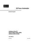
Fig. 1
Fig. 2
8
1
3
7
9
4
14
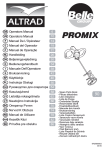
Fig. 3
Fig. 4
10
8
11
14
Fig. 5
Fig. 6
2
2
12
12
Fig. 7
Fig. 8
Important!
It is essential that you read the instructions in this manual before operating this machine.
Attention!
Il est indispensable que vous lisiez les instructions contenues dans ce manuel avant la mise en service
de l’appareil.
Achtung!
Bitte lesen Sie unbedingt vor Inbetriebnahme die Hinweise dieser Bedienungsanleitung.
¡Atención!
Es imprescindible que lea las instrucciones de este manual antes de la puesta en servicio.
Attenzione!
Prima di procedere alla messa in funzione, è indispensabile leggere attentamente le istruzioni contenute
nel manuale.
Let op!
Het is van essentieel belang dat u de instructies in deze gebruiksaanwijzing leest vooraleer u dit toestel
in gebruik neemt.
Atenção!
É indispensável que leia as instruções deste manual antes de utilizar a máquina.
OBS!
Denne brugervejledning skal gennemlæses inden maskinen tage i brug.
Observera!
Det är nödvändigt att läsa instruktionerna i denna bruksanvisning innan användning.
Huomio!
On ehdottoman välttämätöntä lukea tässä käyttöohjeessa annetut ohjeet ennen käyttöönottoa.
Advarsel!
Det er meget viktig at du leser denne brukerveiledningen før du tar maskinen i bruk.
Uwaga! !"#$!%&'($)"*)"+#-/:%';-<=*)='">-/!(#!"*)=?*=@":%;-*)"A!*)"!=$-!*=C&)G!!=@"A"*)=+)
!=<='%+)<*)*)"J&!%+$-#GA!*);/
$
¢£¤£¥
K"$-/LMN"J'"'"*'-$QM&'-J#QMN"?*"L&)$Q"R'"'"$-;%*%/N"#"*TN'-+'-*UN-#/
Figyelem! V"@'T'@"*W@X-*'-&?Y->%=J"@"*Y=&!*U@=')Z'+/'='[\=*X->@=@'"@]MU&-;='=!W!"+\"Y"@%"!T&"@]''
elolvassa!
£§
_&'""&"*`)=@&xA)')`))*&'/A`)/*)@"#)*=A"&'+=*/=@{*=)*'"#"-$"="==A"&'/)=$=='
8]PDQƯEX
|N=}>)?@=)J~&$)+&+=}*=&#=\)*=*=&)!@=&}'/)*&'/;A)J=&=J-;=&>+='
'ơPHVLR
)"$=##=+)";&$@-='/-')$)"'=)&(?&N=\/?;=#$"&;=)'%'/+'")-&")*&'/;A)J-&"$='");'/&
nurodymus.
7lKWLV
Enne trelli kasutama hakkamist tuleb käesolevas juhendis esitatud juhised kindlasti läbi lugeda.
8SR]RUHQMH
K"-$Y-#*-J"#=$-R)'='"-N"/$/'"$)J"/$-=\"-N->/"=J=
Pomembno! "#/$-=\-'">=&'-J=?-\N"!*-$"\")'"*=N-#)@=)!'">=$)-R*);=
'{OHåLWp
"$UA-/&'+'-!=)=#"*M+J"#
@"L)'T?\%&'"&)$"RM'=@)$-;%*%N'-+'-*UN-#"
©ª«¬«®
Dikkat!
)Y=! *¡=@ ¢' @+=& *#=*£*A"\/; @=N/!#=\/@/*=*'=@)+='@= -;/+=* !!-/*@/#/
|/\J"A''-'"AY*)A=@+-#)X)A=')-*&¤|-/&T&"N"#"+-#)X)A=')-*&'"AY*)¥/"&¤¦"AY*)&AY"§*#"/*>"*N-\"Y=@'"*¤
|/J"'-=+-#)X)A=A)-*"&'TA*)A=&¤-*)&"N=#)"N"*'/=@)+-#)X)AY"'"A*)AY"¤¦"AY*)&AY"<)J!)>)*>"*N--\"Y-/#"*¤
-+"&"N=#"+-#)X)A=¡¨"&'TA*)A=&¤©"#X-\"Y-@#X-'";*)&;"ª*#)*>"¤©"#X£\"Y«@@X£'";*)&;=¬*#)*>=¤
¦";*)&"'+//'-;&"'N=='==*¤©"#X-\"Y-@#-+'";*)&;""*#)*>"¤®¯°
¯±
/
³!=&'!":"*)"++-#%X);=AJ)'"AY*)A!*%AY¤³+´*%'"AY*)A;AYZ#=JµN%Y=!"*%¤ ¶+·&!=;)+[#-&M'U&J->U'X"**'='J/;¤
|/\"!"N=+-#)X)A=`))@-'"Y*)A"¤='/=+')"&}\=&+=)*}''"Y*)&;-&=;&'/@)"@/+/&¤=&)@)";=*''")&G#=%')'"AY*)*)/&$=;")')+/&¤
¦"Y*)@)&"#+//#='/&"#N¨)+=@);/#¤Podloæno tehniËkim promjenama ¤¦"Y*)R*"&$"+"+\"#-$/R"*"¤
¦"AY*)A;T!+"*%N%Y=#"*T¤ ¸¹º»¼½¾¤¦";*);#"¿)¢);@);Y=;; &=;@ # GB
FR
DE
ES
IT
NL
PT
DK
SE
FI
NO
RU
PL
CZ
HU
RO
LV
LT
EE
HR
SI
SK
GR
TR
English
DESCRIPTION
1. Grinding wheel
2. Tool-less wheel guard
3. Rotating handle
4. Handle lock button
5. On/off switch
6. Safety lock
7. Disc Äange
8. Clamp nut
9. Spindle shaft
10. Wrench
11. Spindle lock button
12. Wheel guard lock lever
13. Live tool indicator
14. Auxiliary handle
h.
SAFETY WARNINGS SPECIFIC FOR GRINDING
OPERATIONS
i.
a. This power tool is intended to function as
a grinder tool. Read all safety warnings,
instructions, illustrations and specifications
provided with this power tool. Failure to follow
all instructions listed below may result in electric
shock, Ìre and/or serious injury.
b. Operations for which the power tool was not
designed may create a hazard and cause
personal injury.
c. Do not use accessories which are not
specifically designed and recommended by the
tool manufacturer. Just because the accessory
can be attached to your power tool, it does not
assure safe operation.
d. The rated speed of the accessory must be at
least equal to the maximum speed marked on
the power tool. Accessories running faster than
their rated speed can break and Äy apart.
e. The outside diameter and the thickness of your
accessory must be within the capacity rating
of your power tool. Incorrectly sized accessories
cannot be adequately guarded or controlled.
f. The arbour size of wheels, flanges, backing
pads or any other accessory must properly
fit the spindle of the power tool. Accessories
with arbour holes that do not match the mounting
hardware of the power tool will run out of balance,
vibrate excessively and may cause loss of control.
g. Do not use a damaged accessory. Before each
use inspect the accessory such as abrasive
wheels for chips and cracks, backing pad
for cracks, tear or excess wear, wire brush
for loose or cracked wires. If power tool or
accessory is dropped, inspect for damage
j.
k.
l.
m.
n.
o.
p.
q.
1
or install an undamaged accessory. After
inspecting and installing an accessory,
position yourself and bystanders away from
the plane of the rotating accessory and run the
power tool at maximum no-load speed for one
minute. Damaged accessories will normally break
apart during this test time.
Wear
personal
protective
equipment.
Depending
on
application,
use
face
shield, safety goggles or safety glasses.
As appropriate, wear dust mask, hearing
protectors, gloves and workshop apron
capable of stopping small abrasive or
workpiece fragments. The eye protection must
be capable of stopping Äying debris generated by
various operations. The dust mask or respirator
must be capable of Ìltrating particles generated
by your operation. Prolonged exposure to high
intensity noise may cause hearing loss.
Keep bystanders a safe distance away from
work area. Anyone entering the work area
must wear personal protective equipment.
Fragments of workpiece or of a broken accessory
may Äy away and cause injury beyond immediate
area of operation.
Hold power tool by insulated gripping surfaces
only, when performing an operation where the
cutting accessory may contact hidden wiring
or its own cord. Cutting accessory contacting a
“live” wire may make exposed metal parts of the
power tool “live” and shock the operator.
Position the cord clear of the spinning
accessory. If you lose control, the cord may be cut
or snagged and your hand or arm may be pulled
into the spinning accessory.
Never lay the power tool down until the
accessory has come to a complete stop. The
spinning accessory may grab the surface and pull
the power tool out of your control.
Do not run the power tool while carrying it at
your side. Accidental contact with the spinning
accessory could snag your clothing, pulling the
accessory into your body.
Regularly clean the power tool’s air vents. The
motor’s fan will draw the dust inside the housing
and excessive accumulation of powdered metal
may cause electrical hazards.
Do not operate the power tool near flammable
materials. Sparks could ignite these materials.
Do not use accessories that require liquid
coolants. Using water or other liquid coolants may
result in electrocution or shock.
Use only wheel types that are recommended
for your power tool and the specific guard
GB
FR
DE
ES
IT
NL
PT
DK
SE
FI
NO
RU
PL
CZ
HU
RO
LV
LT
EE
HR
SI
SK
GR
TR
English
designed for the selected wheel. Wheels for
which the power tool was not designed cannot be
adequately guarded and are unsafe.
r. The guard must be securely attached to the
power tool and positioned for maximum safety,
so the least amount of wheel is exposed
towards the operator. The guard helps to protect
operator from broken wheel fragments and
accidental contact with wheel.
s. Wheels must be used only for recommended
applications. For example, do not grind with
the side of cut-off wheel. Abrasive cut-off wheels
are intended for peripheral grinding, side forces
applied to these wheels may cause them to shatter.
t. Always use undamaged wheel flanges that are
of correct size and shape for your selected
wheel. Proper wheel Äanges support the wheel
thus reducing the possibility of wheel breakage.
Flanges for cut-off wheels may be different from
grinding wheel Äanges.
u. Do not use worn down wheels from larger
power tools. Wheel intended for larger power tool
is not suitable for the higher speed of a smaller tool
and may burst.
power tool will move if kickback occurs.
Kickback will propel the tool in direction opposite
to the wheel’s movement at the point of snagging.
d. Use special care when working corners, sharp
edges etc.
Avoid bouncing and snagging the accessory.
Corners, sharp edges or bouncing have a tendency
to snag the rotating accessory and cause loss of
control or kickback.
e. Do not attach a saw chain woodcarving blade
or toothed saw blade. Such blades create
frequent kickback and loss of control.
ADDITIONAL SAFETY WARNINGS SPECIFIC FOR
GRINDING OPERATIONS
a. Check that the speed marked on the grinding
wheel is equal to or greater than the rated speed
of the tool.
b. Ensure that the dimensions of the grinding wheel
are compatible with the tool and that the wheel Ìts
the spindle.
c. Grinding wheels must be stored in a dry place.
d. Do not store objects on top of the grinding wheels.
e. Grinding wheels must not be used for any
operation other than grinding.
f. Inspect the grinding wheel before use to ensure
that it is not chipped or cracked. Chips or cracks
can cause the wheels to shatter, resulting in
possible serious injury.
g. Ensure that the grinding wheel is correctly mounted
and tightened before use and run the tool at noload speed for 30 seconds in a safe position. Stop
immediately if there is considerable vibration or if
other defects are detected. If this condition occurs,
check the tool to determine the cause.
h. Do not use separate reducing bushings or adapters
to adapt large hole grinding wheels.
i. Check that the workpiece is properly supported.
j. Ensure that sparks resulting from use do not create
a hazard e.g. do not hit people, or ignite Äammable
substances.
k. Always use protective safety glasses and ear
protectors.
l. Use other personal protective equipment such as
gloves, apron and helmet when necessary.
m. Never place the tool on the Äoor or other surfaces
while it is running. Grinding wheels continue to
rotate after the tool is switched off. Never touch
the wheel or place it on the Äoor or other surfaces
while it is rotating.
n. The Äange and clamp nut must have same outer
diameter.
o. Use the tool only for approved applications. Never
use coolants or water or use the tool as a Ìxed
KICKBACK AND RELATED WARNINGS
Kickback is a sudden reaction to a pinched or snagged
rotating wheel, backing pad, brush or any other accessory.
Pinching or snagging causes rapid stalling of the rotating
accessory which in turn causes the uncontrolled power tool
to be forced in the direction opposite of the accessory’s
rotation at the point of the binding.
For example, if an abrasive wheel is snagged or pinched
by the workpiece, the edge of the wheel that is entering
into the pinch point can dig into the surface of the material
causing the wheel to climb out or kick out. The wheel may
either jump toward or away from the operator, depending
on direction of the wheel’s movement at the point of
pinching. Abrasive wheels may also break under these
conditions.
Kickback is the result of power tool misuse and/or incorrect
operating procedures or conditions and can be avoided by
taking proper precautions as given below.
a. Maintain a firm grip on the power tool and
position your body and arm to allow you to
resist kickback forces. Always use auxiliary
handle, if provided, for maximum control
over kickback or torque reaction during startup. The operator can control torque reactions or
kickback forces, if proper precautions are taken.
b. Never place your hand near the rotating
accessory. Accessory may kickback over your
hand.
c. Do not position your body in the area where
2
GB
FR
DE
ES
IT
NL
PT
DK
SE
FI
NO
RU
PL
CZ
HU
RO
LV
LT
EE
HR
SI
SK
GR
TR
English
tool.
p. Grip the tool securely with both hands while
operating.
Safety Alert
Volts
Hz
Hertz
470 mm
Net weight
6.0 kg
NOTE: Be sure to check the nameplate on the product,
because the voltage is subject to change depending on
the area in which the product is to be used.
SYMBOL
V
Overall length
Maximum circumferential speed of grinding wheel: 4,800
m/min.
Alternating Current
Example of calculation
W
Watts
3.14 x 230 x 6,000/1,000 =
4,333.2
nº
No-load speed
3.14 x 180 x 6,000/1,000 =
3,391.2
n
Rated speed
Revolutions or reciprocations per minute
Circumferential speed of
grinding wheel
4,333.2/3,391.2
CE Conformity
Wheel diameter
230/180
Rated speed of grinder
6,000
minÕ¹
Double insulation
STANDARD ACCESSORIES
Wear ear protection
Auxiliary handle
Wear eye protection
A grinding wheel is included in the standard accessories
for some countries.
Please read the instructions carefully before
starting the machine.
See gure 4.
OPERATION
Waste electrical products should not be
disposed of with household waste. Please
recycle where facilities exist. Check with your
Local Authority or retailer for recycling advice.
WARNING
Keep safety guards in place. Never cover the air vents
since they must always be open for proper motor
cooling.
Recycle raw materials instead of disposing
of as waste. The machine, accessories and
packaging should be sorted for environmentalfriendly recycling.
The key to efÌcient operating is controlling the pressure
and surface contact between the disc and workpiece. Flat
surfaces are ground at an acute angle, usually 10 to 20
degrees with the workpiece. Allow the disc to reach full
speed before starting to grind. Too great an angle causes
concentration of pressure on a small area which may
gouge or burn work surface.
SPECIFICATIONS
Grinding wheel
230 mm (9 in)
Frequency
50 Hz
Voltage
230 V - 240 V
SWITCH
See gure 2.
Input
2000 W
To switch on the unit, press forward the safety lock
and then press the on/off switch.
Spindle thread
M14
To switch off the unit, release the on/off switch.
Rated speed
6000 minÕ¹
3
GB
FR
DE
ES
IT
NL
PT
DK
SE
FI
NO
RU
PL
CZ
HU
RO
LV
LT
EE
HR
SI
SK
GR
TR
English
ADJUSTING THE ROTATING HANDLE POSITION
MAINTENANCE
See gure 3.
1. Turn off the tool.
2. Press and hold the handle lock button, then turn the
rotating handle to the desired position until it snaps
in place.
After use, check the tool to make sure that it is in good
condition.
It is recommended that you take this tool to a Ryobi
authorized service center for a through cleaning and
lubrication at least once a year.
WARNING
WARNING
Do not adjust the rotating handle while the tool is in
operation.
Do not make any adjustments while the motor is in
motion.
Always disconnect the power cord from the socket
before changing removable or expendable parts
(grinding disc, cutting disc etc.), before lubricating or
working on the unit.
THREE-POSITION AUXILIARY HANDLE
See gure 5.
SpeciÌcally designed and angled to three-position for
maximum comfort and control.
WARNING
MOUNTING THE GRINDING WHEEL
To ensure safety and reliability, all repairs should be
performed by an authorized service center or other
qualiÌed service organization.
See gure 4 - 6.
WARNING
Check carefully whether or not there are cracks in the
wheel. Replace a cracked wheel immediately.
Attach the disc flange, the grinding wheel and the
clamp nut to the spindle shaft.
Be sure the disc flange is properly seated on the
spindle shaft.
Depress the lock button located on the right side of
gear case.
Using the wrench provided, tighten the clamp nut in a
clockwise direction.
TOOL-LESS WHEEL GUARD
See gure 7 - 8.
Release the wheel guard lock lever then turn the tool-less
wheel guard to the desired position. The maximum turning
angle is 90° on either side; otherwise the guard cannot
be locked.
LIVE TOOL INDICATOR
This tool features a live tool indicator which illuminates as
soon as the tool is connected to the supply. This warns the
user that the tool is connected and will operate when the
switch is pressed.
4