1
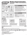
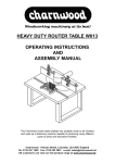
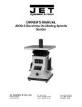
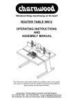
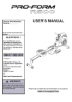
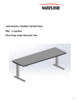
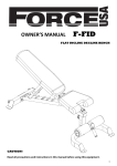
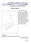
GARAGE DOOR OPERATOR USER’S MANUAL
(FBC180 / FBC200)
FBC180 / FBC200 GARAGE DOOR OPERATOR USER’S MANUAL
OUTLINE
1.
Safety instructions………………………………3
2.
Main features …………………………………3
3.
Technical specifications ………………………4
4.
Check …………………………………………4
5.
Installation and adjustment ……………………4
6.
Programming …………………………………8
7. External terminal connections …………………14
8.
Maintenance …………………………………15
9. Troubleshooting ………………………………15
2
FBC180 / FBC200 GARAGE DOOR OPERATOR USER’S MANUAL
1.Safety instructions
Carefully read and follow all safety precaution, warnings before attempting to install and use
this garage door operator, incorrect installation can lead to severe injury.
l
The installation should be carried out by a qualified technician.
l
To avoid electrical shock, disconnect the power cord from the mains power outlet before
doing any repairs or removing the cover.
l
The door operator must be grounded.
l
Before installation of the door operator, the door should be carefully checked for being
kept well balance. The door must be in good working order. Open and close the door
manually, make sure the door can be moved smoothly.
l
No one or vehicle is allowed to enter or leave the garage while the remoter is being
installed, do not allow children to play near the door.
l
Locate any fixed control: within sight of door but away from all moving parts of the door
and at a height of more than 1.5m above the ground to avoid children reaching it.
l
Keep remote controls away from children, to prevent the door operator from being
activated involuntarily.
l
When opening or closing the door, do not attempt to walk or drive through the door.
l
l
The door should only be operated when it can be observed to avoid accidents.
Install and adjust the manual release so that the handle hangs less than 1.5m above the
floor.
l
Our company reserves the right to change the design and specification without prior
notification.
Failure to comply with the instructions above may result in personal injury or property damage.
Our company does not accept responsibility for damage or injury resulting from installing this
operator.
2. Main features
l
The door operator is designed for garage door.
l
The control unit regulates all the necessary functions such as automatic lighting control,
automatic memory, automatic close, automatic reverse and photocell protection etc.,
extremely quiet and smooth operation.
l
Courtesy light will turns on in using and turns off after 3 minutes.
l
The operator memorizes the limit positions and unique braking system that slows the unit
down at the end of its travel. Soft start and soft stop control guarantees extremely smooth
and quiet operation.
l
Automatic reversion on obstruction during closing procedure.
l
The controller has a security LOCK function which prevents operation of the door from
transmitter.
l
In the event of power failure, the release device makes it possible to open and close the
door manually.
l
Smart controller and encoder system. Hopping code remote control with max. 20 pcs
hand transmitters.
l
Battery, button switch and infrared photocell are optional.
3
FBC180 / FBC200 GARAGE DOOR OPERATOR USER’S MANUAL
3. Technical specifications
Model
FBC180
FBC200
Motor power
80 W
100 W
Lifting capacity
800 N
1000 N
2
16 m2
Max. door size
12 m
Power supply
220X(1±10%)V AC 50-60Hz
Motor
24VDC
Ambient temperature
-20ºC~+50ºC
Working humidity
≦90%
Courtesy light time
3 minutes
Radio frequency
433.92 MHz
Transmitter type
Rolling code
Transmitter battery
27A 12V
Bulb
24V 5W
4. Check
After receiving the product, you should make an unpack-inspection, in which you should check
whether the product was damaged. If you have any problem please contact dealer.
4. Powerhead
bracket (x3)
2. Chain drive rail assembly (x1)
3. Shuttle&Manual release cord(x1)
1.Powerhead (x1)
5. Header bracket (x1)
Screw(M8x16mm)
6. Door bracket (x1)
Screw cap(M8)
Screw cap(M6)
7. L arm (x1)
Screw(M6x22mm)
Screw(M8x55mm)
8. Straight arm (x1)
Pin
R pin
9. Angle iron (x1)
11. Transmitter (x2)
10. Screw / Screw cap / Pin and R pin
Fig.1
5. Installation and adjustment
Step1
l
Check the door is in good working condition, manually open and close the door to make
sure the door operates smoothly and freely.
l
The door must be well balanced.
l
Check to see if there is a solid frame in the wall above the center of the door.
l
Close the door.
l
Measure the door width, mark the centerline of the door using a pencil, and extend the
line down to the door surface, then up the wall above the door.
l
Check the installation height of the operator. Slowly open garage door and observe the
4
FBC180 / FBC200 GARAGE DOOR OPERATOR USER’S MANUAL
highest point of door while moving. Close the door again and mark this highest point on
the wall, mark a horizontal line across the vertical centerline around 40mm above the
highest point. (Note: there should be 80mm space between this horizontal line to the
ceiling. If there is not enough space, please use the max. height possible to allow the
40mm
header bracket to be fitted properly. )
Garage door
Fig.2
Highest point
Highest point
Tilt door
Sectional door
Fig.3
Fit the header bracket to the wall above the door, the centerline of the door should align
with the centerline of the bracket, The bottom edge of the bracket should align with the
horizontal line. Fix the header bracket to the wall with expansion bolts.
Centerline
Header bracket
40mm
l
Fig.4
5
Horizontal line
Hightest point of
garage door
FBC180 / FBC200 GARAGE DOOR OPERATOR USER’S MANUAL
Step 2
l
Insert the shuttle into the groove of the chain drive rail. Be sure it faces the right direction
(the release arm on the shuttle towards the powerhead). Fasten the four screws
(M6x22mm).
Pin and R pin (x1)
M6x22mm Screw (x4)
Straight arm
The release arm towards
the powerhead.
Fig.5
Step 3
l
Place the powerhead on the floor, add cardboard packing to protect the powerhead from
scratching by the floor. Attach the powerhead unit to the chain drive rail, make sure the
spindle is inserted into the chain drive, then fix the brackets.
M o u n tin g b ra c k e t (N o t in c lu d e d in a c c e s s o rie s )
M 8 X 1 6 m m s c r e w (x 2 )
M 8 s c re w c a p (x 2 )
P o w e rh e a d b ra c k e t
M 6 s c re w c a p (x 4 )
A n g le iro n
S te e l ra il
M 8 X 1 6 m m s c re w ( x 2 )
M 8 s c re w c a p (x 2 )
P o w e rh e a d u n it
Fig.6
Step 4
l
Close the door.
l
Place the operator in the center of the floor. Lift the front end of the rail up to the header
bracket that has been mounted above the garage door, insert the bolt and secure it with
nut see Fig.7.
6
FBC180 / FBC200 GARAGE DOOR OPERATOR USER’S MANUAL
M8 Expansion bolt (Not
included in accessories)
Header bracket
Bolt and nut
Fig.7
Step 5
l
Raise and support the powerhead with a ladder and line up the rail with the centerline
marked on the door. The rail must be level.
l
Fix the rail to ceiling with mounting brackets (not included in accessories) and angle iron
see Fig.6, make sure that the rail is level. If necessary, Check the door does not touch any
part of the rail by opening or closing it manually.
Fig.8
Step 6
Fix the door bracket on the top edge of the door with screws (M8X55) and screw caps (M8).
Link the L arm to the door bracket with pin and R pin. Link the straight arm to the shuttle with
pin and R pin, then connect L arm to straight arm with two screws (M8X16) and screw caps
(M8), ensure the door arm can be moved freely. See Fig.8, Fig.9 and Fig.10.
7
FBC180 / FBC200 GARAGE DOOR OPERATOR USER’S MANUAL
Pin and R pin(X1)
Door bracket
M8X16mm Screw(X2)
M8 Screw cap(X2)
M8x55 screw(X2)
M8 screw cap(X2)
L arm
Fig.9
Shuttle
Straight arm
L arm
Door bracket
Fig.10
Manual operation
If the door has to be operated manually due to a power cut or malfunction of the automated
system, pull the release rope, open and close the door manually. To reconnect the door, move
the door by hand until it engages into the chain shuttle.
6. Programming
SET button: Mode set and Confirm function
CODE button: Transmitter code set and clear function
UP button: Up limit
DOWN button: Down limit
8
FBC180 / FBC200 GARAGE DOOR OPERATOR USER’S MANUAL
UP
SET
E
COD
DO
WN
Fig.11
l
With power on, the bulb will turn on about 2 seconds and then turn off. The LED will
display number from ’99’ to ’11’, when ‘▬ ▬’ appears on the LED display, the operator is
now in normal state.
COD
E
COD
E
UP
S ET
UP
S ET
DOW
N
CO D
DOW
N
CO D
E
E
SET
SET
UP
UP
DOW
N
DOW
N
Fig.12
Transmitter
l
Button 1, button 2, button 3: The remote control works in a single channel mode. With
each press of the remote control button which has been programmed, the gate will open,
stop, close or stop cycle.
l
Button 4: LOCK button
Button 1
Button 3
Button 2
Button 4
Fig.13
9
FBC180 / FBC200 GARAGE DOOR OPERATOR USER’S MANUAL
Adding extra transmitter (learn)
1. Press the CODE, ‘Su’ is indicated on the LED display.
2. Press the transmitter button which you want to use (button 1, 2, 3), then press the same
button again.
3. ‘Su’ on the LED display will flash.
4. ‘▬ ▬’ is indicated on the LED display, then the learning process is finished.
Up to 20 transmitters may be used.
C OD
UP
S ET
E
Press the transmitter
button twice.
DO
WN
1
E
UP
SET
2
DOW
N
3
UP
SET
E
COD
COD
DOW
N
4
Fig.14
Deleting stored transmitters
1. Press and hold CODE, ‘Su’ is indicated on the LED display.
2. Do not release the button until ‘dL’ flashes.
3. ‘▬ ▬’ is indicated on the LED display, this indicates that all stored transmitters have been
deleted completely.
UP
S ET
UP
SET
DOW
N
E
COD
DOW
N
E
COD
1
2
UP
SET
DOW
N
E
COD
3
Fig.15
Open and Close limit
1. Press and hold SET four seconds until ‘P1’ is indicated on the LED display. The operator is
now in programming mode.
10
FBC180 / FBC200 GARAGE DOOR OPERATOR USER’S MANUAL
2. Press SET again, ‘OP’ is indicated on the LED display.
3. Press and hold UP to set the open limit, ‘OP’ on the LED display will flash, release the
button until the door has reached desired position.
4. Press SET to confirm the open limit position, the LED will now indicated the ‘CL’.
5. Press and hold DOWN to set the close limit, ‘CL’ on the LED display will flash, release the
button until the door has reached desired position.
6. Press SET to confirm the close limit position.
7. The door will now do a complete open & close cycle.
E
COD
UP
SET
DOW
N
E
COD
1
E
COD
DOW
N
E
COD
DOW
N
4
UP
SET
UP
SE T
3
E
COD
DOW
N
2
UP
SET
UP
SE T
DOW
N
E
C OD
UP
SE T
5
DO
WN
6
The door will do a complete open
&close cycle.
7
E
COD
SET
UP
DOW
N
Fig.16
Adjusting obstruction force sensitivity
If the door meet an obstruction during closing, it will stop and reverse about 15cm~20cm.
1. Press and hold SET four seconds until ‘P1’ is indicated on the LED display.
2. Press UP button, ‘P2’ is indicated on the LED display.
3. Press the SET, the unit is now in force adjustment mode. Note: the factory preset is F5.
4. Press UP to increase force setting, maximum force setting is level 9 (F9). Press DOWN to
decrease force, minimum force setting is level 1(F1).
5. Press SET to confirm.
11
FBC180 / FBC200 GARAGE DOOR OPERATOR USER’S MANUAL
C OD
UP
S ET
E
DOW
C OD
N
E
UP
SE T
1
DOW
N
2
Decrease force
C OD
UP
SE T
E
D OW
C OD
N
E
3
COD
4
DOW
N
Increase force
UP
S ET
E
UP
SE T
DOW
N
5
Fig.17
Infrared photocell
1. Press and hold SET four seconds until ‘P1’ is indicated on the LED display.
2. Press UP button twice until ‘P3’ is indicated on the LED display.
3. Press the SET. The factory preset is ‘H0’.
4. Press UP (‘H1’ will display) to enable the photocell. Press DOWN (‘H0’ will display) to
disable the photocell.
5. Press SET to confirm the setting.
C OD
E
UP
S ET
DO
WN
COD
E
1
COD
E
DO
WN
COD
E
E
4a
UP
SET
DOW
N
4b
UP
S ET
3
COD
DO
WN
2
UP
SET
UP
S ET
COD
E
Fig.18
12
Photocell enable
UP
S ET
DOW
N
5
Photocell disable
DO
WN
FBC180 / FBC200 GARAGE DOOR OPERATOR USER’S MANUAL
Automatic closing (1~9 minutes adjustable)
1.
2.
3.
4.
Press and hold SET four seconds until ‘P1’ is indicated on the LED display.
Press UP button three times until ‘P4’ is indicated on the LED display.
Press the SET. The factory preset is ‘b0’.
Press UP or DOWN to set auto close time (b0-b9). Press UP to increase timer, press
DOWN to decrease timer. Note: To disable auto close set timer to ‘b0’.
5. Press SET to confirm the setting.
NOTE: Automatic closing is available only when the door is in fully opened position.
COD
E
UP
S ET
DOW
C OD
N
E
UP
S ET
1
DOW
N
2
Decrease time
C OD
E
UP
SE T
DO
WN
CO D
3
C OD
E
E
UP
S ET
4
D OW
N
Increase time
UP
S ET
D OW
N
5
Fig.19
Door lock mode
1. Press and hold SET four seconds until ‘P1’ is indicated on the LED display.
2. Press UP button four times until ‘P5’ is indicated on the LED display.
3. Press the SET. The factory preset is ‘UL’.
4. Press UP to enable the door lock (‘LC’ will display). Press DOWN to disable to door lock
(‘UL’ will display).
5. Press SET to confirm the setting.
NOTE: LOCK function is available only when the door is in fully closed position.
After setting Door LOCK function, the transmitter locked, you need press button 4 of
transmitter to unlock, then press the other buttons to operate the door.
13
FBC180 / FBC200 GARAGE DOOR OPERATOR USER’S MANUAL
C OD
E
UP
SET
D OW
C OD
N
E
1
CO D
E
E
UP
S ET
D OW
C OD
N
E
DO
4b
UP
SET
4a
UP
SET
DO W
N
2
3
C OD
UP
SET
WN
C OD
E
Fig.20
7. External terminal connections
Fig.21
14
N
Door lock enable
UP
SET
DO
5
Door lock disable
D OW
WN
FBC180 / FBC200 GARAGE DOOR OPERATOR USER’S MANUAL
8. Maintenance
l
Check the door once a month. The door should be carefully checked for balance. The
door must be in good working order.
l
Check and add lubricant regularly.
l
The auto-reverse function should be regularly inspected, and adjusted if necessary. For
service, call an experienced serviceman.
l
We suggest for safety reasons, photocells be used on all doors.
l
Disconnect from mains supply before replacing bulb.
l
Be sure to read the entire manual before attempting to perform any installation or service
to the door operator.
9. Troubleshooting
Trouble
The door fails to open
and close. LED display
does not light.
Possible causes
1. Power is OFF
1. Make sure that power is ON.
2. Fuse blown
2. Replace fuse.
After program the open
and close limit, the motor
Solutions
Open and close limit
fails to work.
Reprogram the open and close
limit.
1. Infrared beam is obstructed.
1. Remove obstructions.
The door can open, fails
2. Infrared photocell function is
2.
to close.
enable, but the photocell has not
photocell function is disable.
Make
sure
the
infrared
been installed.
Remote control does not
1. Battery level may be low.
work.
2. Transmitter
1. Replace the battery inside the
transmitter.
2. Re-program the transmitter.
Battery level may be low.
Replace battery.
The transmitter operating
distance becomes short
or indicator light on the
transmitter begins to dim.
15