1
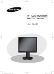
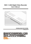
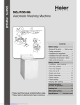
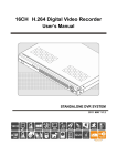
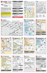
HG600/HG1000 SECTIONAL DOOR OPERATOR
USER’S MANUAL
HG600/HG1000 SECTIONAL DOOR OPERATOR USER’S MANUAL
OUTLINE
1.
Safety instructions………………………………3
2.
Description and features ………………………3
3.
Technical specifications ………………………3
4.
Check …………………………………………4
5.
Installation and adjustment ……………………4
6.
Programming …………………………………8
7.
External terminal connection …………………11
8.
Maintenance …………………………………12
9. Troubleshooting ………………………………12
2
HG600/HG1000 SECTIONAL DOOR OPERATOR USER’S MANUAL
1.Safety instructions
Carefully read and follow all safety precaution, warnings before attempting to install and use
this sectional door operator, incorrect installation can lead to severe injury.
The installation should be carried out by a qualified technician.
To avoid electrical shock, disconnect the power cord from the mains power outlet before
doing any repairs or removing the cover.
Before installing, make sure that the door is in good mechanical condition, the door must
be well balanced. Check that the door operates smoothly and easily.
Before installing the operator, remove all unnecessary ropes and disable equipment, such
as locks etc..
The garage door should only be used when in full view of the door.
No one or vehicle is allowed to enter or leave the garage while the remoter is being
installed, do not allow children to play near the door.
Locate any fixed control: within sight of door but away from all moving parts of the door
and at a height of more than 1.5m above the ground to avoid children reaching it.
Install and adjust the manual release so that the handle hangs less than 1.8m above the
floor.
Failure to comply with the instructions above may result in personal injury or property damage.
Our company does not accept responsibility for damage or injury resulting from installing this
operator.
2. Description and features
The garage door operator is designed for residential overhead sectional and tilt doors. It
operates on 240V AC.
The operator memorizes the limit positions and unique braking system that slows the unit
down at the end of its travel.
Smart controller and encoder system. Rolling code transmitter.
The operator is equipped with a manual release lever which allows manual operation of
The controller has a security LOCK function which prevents operation of the door from
the door in case of power failure.
transmitter.
3. Technical specifications
Model
HG600
HG1000
Motor
24V DC 100W
24V DC 120W
600N
1000N
Open & close force
Max. door size
10m
Power Input
2
14m
220V~240VAC±10% 50Hz
Courtesy light time
3 minutes
Working temperature
-20°C ~ 50°C
Radio frequency
433.92MHz
Transmitter type
Rolling code
Transmitter battery
23A 12V Battery
Bulb
220V~240V 25 watt E14 bulb
3
2
HG600/HG1000 SECTIONAL DOOR OPERATOR USER’S MANUAL
4. Check
After receiving the product, you should make an unpack-inspection, in which you should check
whether the product was damaged. If you have any problem please contact dealer.
Connecting bracket (x2)
For aluminium rail only
Powerhead
bracket (x2)
Wall bracket (x1)
Door bracket (x1)
Aluminium rail assembly (x1) or Steel rail assembly (x1)
Transmitter (x2)
L arm (x1)
Straight arm (x1)
Powerhead (x1)
Note: If the operator is equipped with steel rail, two pieces of connecting brackets are not included.
Fig.1
5. Installation and adjustment
Step1
Check the door is in good working condition, manually open and close the door to make
sure the door operates smoothly and freely.
The door must be well balanced.
Check to see if there is a solid frame in the wall above the center of the door.
Close the door.
Mark the centerline of the door using a pencil, and extend the line down to the door
surface, then up the wall above the door.
Check the installation height of the operator. Slowly open garage door and observe the
highest point of door while moving. Close the door again and mark this highest point on
the wall, mark a horizontal line across the vertical centerline around 40mm above the
highest point. (Note: there should be 80mm space between this horizontal line to the
ceiling. If there is not enough space, please use the max. height possible to allow the
header bracket to be fitted properly. )
Fit the header bracket to the wall above the door, the centerline of the door should align
with the centerline of the bracket, The bottom edge of the bracket should align with the
horizontal line. Then fix the header bracket with screws.
4
40mm
HG600/HG1000 SECTIONAL DOOR OPERATOR USER’S MANUAL
Garage door
Fig.2
Highest point
Highest point
Tilt door
Sectional door
Fig.3
40mm
Centerline
Horizontal line
Hightest point of
garage door
Fig.4
Step 2
Aluminium rail (see Fig.5): insert the shuttle into the groove at the end of the rail. Be sure
the release lever on the shuttle faces towards the powerhead. Slide the shuttle along the
rail until it locks into the chain connector.
Steel rail: the shuttle has been fixed into the rail before delivery.
5
HG600/HG1000 SECTIONAL DOOR OPERATOR USER’S MANUAL
Shuttle
Fig.5 Aluminium rail
Step 3
Place the powerhead on the floor, add cardboard packing to protect the powerhead from
scratching by the floor. Attach the powerhead unit to the rail, make sure the spindle is
inserted into the chain drive, then fix the two brackets (see Fig.6 and Fig.7).
Powerhead bracket
Aluminium rail
Drive gear
Powerhead unit
Fig.6 Aluminium rail
Powerhead bracket
Steel rail
Powerhead unit
Fig.7 Steel rail
Step 4
Close the door.
Place the operator in the center of the floor. Lift the front end of the rail up to the header
Raise and support the powerhead with a ladder and line up the tube with the centerline
bracket, and fix it to the bracket with pivot pin and R pin.
marked on the door. The rail must be level.
6
HG600/HG1000 SECTIONAL DOOR OPERATOR USER’S MANUAL
Pivot pin and R pin
Fig.8
Step 5
Aluminium rail (See Fig.9): Locate two pieces of connecting brackets and make sure that the
rail is level, then fix the aluminium rail to ceiling with supplied connecting brackets. If necessary,
you also can add two pieces of brackets (not included in accessories) to fasten the operator
firmly. Check the door does not touch any part of the rail by opening or closing it manually.
Steel rail (See Fig.10): fix the steel rail to ceiling with two pieces of brackets (not included in
accessories).
Connecting bracket
(Suitable for aluminium rail only.)
If necessary, add two pieces
of brackets.
(Not included in accessories.)
Fig.9 Aluminium rail
Bracket
(Not included in accessories.)
Fig.10 Steel rail
7
HG600/HG1000 SECTIONAL DOOR OPERATOR USER’S MANUAL
Step 6
Fix the door bracket on the top edge of the door with bolts. Link the L arm to the door bracket
with pin and R pin. Link the straight arm to the shuttle with pin and R pin, ensure the door arm
can be moved freely.
Straight arm
L arm
Door bracket
Fig.11
Manual operation
If the door has to be operated manually due to a power cut or malfunction of the automated
system, pull the release rope, open and close the door manually. To reconnect the door, move
the door by hand until it engages into the chain shuttle.
6. Programming
SET button: Mode set and Confirm function
LEARN button: Transmitter set and clear function
UP button: Up limit
DOWN button: Down limit
SET
UP
LEARN
DOWN
Fig.12
Adding extra transmitter (learn)
1. Press and hold LEARN, a dot is indicated on the LED display.
2. Press the transmitter button which you want to use (button 1, 2, 4), then press the same
button again.
3. The dot on the LED display will flash then turn off.
4. ’||
||’
|| is indicated on the LED display, then the learning process is finished.
Up to 20 transmitters may be used.
8
HG600/HG1000 SECTIONAL DOOR OPERATOR USER’S MANUAL
SET
UP
SET
UP
LEARN
DOWN
LEARN
DOWN
1
SET
UP
LEARN
DOWN
3
2
4
Fig.13
Erase transmitter
Press and hold LEARN until ’C’ flashes on the LED display. This indicates that all the
transmitters have been erased completely.
SET
UP
SET
UP
LEARN
DOWN
LEARN
DOWN
1
2
Fig.14
Set open and close positions
1. Press and hold SET until number ’1’ is indicated on the LED display.
2. Press and hold UP to set open position, release the button until the door has reached the
desired position. (You also can press DOWN to move the door downward, UP and DOWN
can be used to fine adjust the door position.)
3. Press the SET to confirm the open position, now number ’2’ is indicated on the LED
display.
4. Press and hold DOWN to set close position, release the button until the door has reached
the desired position. (You also can press UP to move the door upward, UP and DOWN can
be used to fine adjust the door position.)
5. Press the SET to confirm the close position.
6. The door will do a complete open and close cycle.
SET
UP
SET
UP
SET
UP
LEARN
DOWN
LEARN
DOWN
LEARN
DOWN
2
1
SET
UP
SET
UP
LEARN
DOWN
LEARN
DOWN
4
5
Fig.15
9
3
HG600/HG1000 SECTIONAL DOOR OPERATOR USER’S MANUAL
Automatic close (0~9 minutes adjustable)
1. Press and hold UP until ’─’ is indicated on the LED display.
2. Press UP to increase the auto close time, press DOWN to decrease time.
3. Set timer to ’0’, the automatic close function will disable.
4. Press SET to confirm the setting.
NOTE: Automatic close function is available only when the door is in fully opened
position.
Increase auto close time
1=1 minute, 2= 2 minutes ...
SET
UP
SET
UP
SET
UP
LEARN
DOWN
LEARN
DOWN
LEARN
DOWN
Decrease auto close time
1
Auto close function disable
2
3
Fig.16
Setting obstruction force
If the door meet an obstruction during closing, it will stop and reverse about 15cm~20cm.
1. Press and hold SET. The LED will display number from ’1’ to ’4’, when the number ’3’
appears on the LED display, release the SET.
2. Press UP to increase the obstruction force, the maximum force is level 9. Press DOWN to
decrease force, the minimum force is level 1.
3. Press SET to confirm.
Increase obstruction force
SET
UP
SET
UP
SET
UP
LEARN
DOWN
LEARN
DOWN
LEARN
DOWN
Decrease obstruction force
1
2
3
Fig.17
LOCK function
1. Press and hold SET. The LED will display number from ’1’ to ’4’, when the number ’4’
appears on the LED display, release SET.
2. Press UP, number ’1’ will be indicated on LED display, LOCK function enable.
3. Press DOWN, number ’0’ will be indicated on LED display, LOCK function disable.
4. Press SET to confirm.
NOTE: LOCK function is available only when the door is in fully closed position.
After setting LOCK function, the door locked, you need press button 3 of transmitter to
unlock, then press the other buttons to operate the door.
10
HG600/HG1000 SECTIONAL DOOR OPERATOR USER’S MANUAL
LOCK function enable
UP
SET
UP
SET
UP
DOWN
LEARN
DOWN
LEARN
DOWN
SET
LEARN
LOCK function disable
1
2
SET
UP
LEARN
DOWN
3
4
Fig.18
Infrared photocell
1. Press and hold DOWN until ’─’ is indicated on the LED display.
2. Press UP, ’H’ is indicated on the LED display, infrared photocell is enable.
3. Press DOWN, ’||
||’
|| is indicated on the LED display, infrared photocell is disable.
4. Press SET to confirm.
SET
UP
SET
UP
SET
UP
LEARN
DOWN
LEARN
DOWN
LEARN
DOWN
1
SET
UP
LEARN
DOWN
3
2
4
Fig.19
7. External terminal connection
PB: Wall switch (N.O.)
GND: Ground
PE: Photocell (N.C.)
+24V: 24V DC power output
+24V
PE
GND
PB
+24V
PE
GND
Phocell receiver
Wall switch
11
PB
Phocell transmitter
HG600/HG1000 SECTIONAL DOOR OPERATOR USER’S MANUAL
Fig.20
8. Maintenance
Check the door once a month. The door should be carefully checked for balance. The
door must be in good working order.
The auto-reverse function should be regularly inspected, and adjusted if necessary. For
service, call an experienced serviceman.
We suggest for safety reasons, photocells be used on all gates.
Disconnect from mains supply before replacing bulb.
Be sure to read the entire manual before attempting to perform any installation or service
to the door operator.
Our company reserves the right to change the design and specification without prior
notification.
9. Troubleshooting
Trouble
The door fails to open
and close. LED display
does not light.
Possible causes
Solutions
1. Power is OFF
1. Make sure that power is ON.
2. Fuse blown
2. Replace fuse.
1. Infrared beam is obstructed.
1. Remove obstructions.
The door can open, fails
2.Infrared
photocell
function
is
to close.
enable, but the photocell has not
2.Make
sure
the
infrared
photocell function is disable.
been installed.
Remote control does not
1. Battery level may be low,
work.
2. Transmitter
1. Replace the battery inside the
transmitter.
2.Re-program the transmitter.
Battery level may be low.
Replace battery.
The transmitter operating
distance is too short.
12