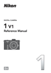
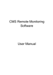
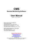
1
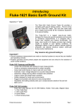
Event recording (or logging)
with a Fluke 287/289
Digital Multimeter
One of the major features of the Fluke
280 Series digital multimeters (DMM) with
TrendCapture is their ability to record
measurement data or “do logging.” This
application note explains what kind of
logging these meters can perform, how
to use the recording feature, and what
information it can provide. This note also
discusses how to use FlukeView® Forms
PC software to increase the power of the
Recording feature.
For the balance of this note, we will
refer to the Fluke 289 DMM, although the
information is equally applicable to the
Fluke 287 DMM.
Application Note
Note: This article references features
included in a firmware upgrade to the 289
DMM released in August, 2008. To obtain
the latest firmware version, visit www.
fluke.com/software-downloads. For
a summary of the changes, reference the
end of this document.
Differences between
the Fluke 289 DMM and
a data logger
The Fluke 289 does not do data
logging in the traditional sense.
Typically, the goal of a data logger is to sample the input signal
at a rate sufficient to track activity that you might find in the
signal. This often means that it
is desirable to sample the input
as fast as possible so you don’t
miss anything. The problem
with this approach is you need
a large storage place for the fast
data sampling that is taking
place. You can also end up wading through a lot of redundant
data that is considered “normal”
to find the exceptional data (or
lack thereof).
The difference between the
Fluke 289 DMM and a traditional logger is that the DMM,
while sampling internally at a
sub-second rate, records only
significant changes in the readings. This technique, called
event recording, requires far
less memory. Still, it does an
effective job of monitoring and
logging data from an input signal, enabling you to detect if
and when the monitored system
is operating abnormally.
The other difference is that
the Fluke 289 DMM can graph
the data onscreen in TrendCapture mode, immediately after
the recording session is completed. TrendCapture is a major
enhancement in the 28X family
over the previous logging capability of the 189, which had to
upload each recording session to
software to graph and view the
results. The Fluke 289 uses similar graphing software (optional)
for detailed analysis, but its ability to graph even rough details
immediately, onscreen, can
be very powerful. In addition,
the 28X can now hold multiple
recording sessions in it’s memory allowing troubleshooters to
get multiple sets of data, possibly at different locations, without
having to download each session as in the past.
Introduction to event
recording
Event recording can be thought
of as an extension of the “Touch
Hold” feature of the original
Fluke 87 DMM. (Touch Hold is
now called “Auto Hold” on the
287/289.) When the Auto Hold
feature is activated, the meter
waits until a period of stability
From the Fluke Digital Library @ www.fluke.com/library
has been reached, then it beeps
and freezes (holds) a stable
reading on the display for the
user to see. If the input changes
to the point that it is no longer
stable, then becomes stable
again, the meter will beep a
second time and hold a new
reading on the display.
Event recording uses a similar
scheme. When the Fluke 289 is
recording, it is looking for periods of stability. For each stable
or unstable period the meter
logs a start time, the initial
reading, stop time, the maximum
reading, minimum reading (and
the times of their occurrence)
and average reading during
that period. The event recording
feature is designed to store only
enough information to describe
any changes; i.e., events, to the
input signal.
Event recording data
The Fluke 289 excels at recording transition events, but while
it has TrendCapture graphing
capability, it does not have the
kind of large graphical display
resolution needed to analyze all
of the event data. This is where
FlukeView Forms software takes
over, allowing you to view the
recorded data in table or graph
form on a PC. An example is
shown in the figure below.
Looking at this data, you can
see that the recording session
started at 1:54:41 PM and ended
at 2:23:47 PM with an elapsed
time of about 29 minutes. You
can also see that the signal
being measured was stable near
119 V for most of the logging
session.
However, there was one
unstable event detected by
the meter during a 1.6-second
period beginning at 2:18 PM.
The graph clearly shows the
switching event that happened
at that time. What is interesting about this example is that
the table of data shows only six
“events” needed to be stored
in the meter memory over the
entire 29 minutes of logging
to capture the essence of what
happened.
What this illustration shows is
that, with event recording, only
a very small amount of memory
is needed to store the information. To capture the same data
using traditional data logging
would require a one-second
sample rate over the entire 29
minutes which would have
produced 1,740 records of data,
yet that level of detail was not
required to detect the problem.
Recording—by the
numbers
Now that we know how the
Fluke 289 records data, let’s
go through the step-by-step
process for recording a desired
signal over time. In this case,
the test will record the signature
of the current drawn by a large
household refrigerator for more
than one day.
The following steps can be
generalized to any recording
situation.
Figure 1.
2 Fluke Corporation Event recording (or logging) with a Fluke 287/289 Digital Multimeter
Step 1
Make sure that the battery
indicator in the upper left hand
corner of the Fluke 289 display
shows at least two of the possible four bars, indicating enough
charge is left for a 24-hour operation. For any longer recording
period, or if in doubt, replace the
batteries with fresh new ones.
Step 2
Connect the meter to the
circuit being measured.
In this example, the ac current
was measured by connecting
a current transformer probe to
the mA jacks of the Fluke 289.
That is because the probe output
is 1 mA/A. We then place the
jaws of the probe around the
circuit conductor in the distribution panel that is connected
to the breaker dedicated to the
refrigerator. If the DMM function
switch is in any position except
A/mA or μA, the meter will beep
to indicate that the switch must
be in one of these two positions to proceed, and the display
information screen will show
the details. In this case, we
want the A/mA function. The
meter will sense the presence
of the lead in the mA jack, and
select the proper circuit for the
recording.
Note: Although not required in this
case, if a signal normally varies a full
point, you might want to estimate a
maximum current or voltage that you
expect to encounter, and set manual
ranging to the higher range. This will
prevent recording multiple events due
to auto-ranging.
Step 3
Press the Save (F2) softkey
and highlight the Record option
using the navigation arrows.
Then, press the Record (F1)
softkey below the display.
At this point, the Recording
information screen appears.
Note that the bottom line of this
display indicates the battery
condition. If the battery is partially discharged, the Battery:
partly empty advisory appears.
See step 1 above.
Step 4
Using the navigation arrows,
highlight Set Duration and
press Edit (F1). Edit the duration
setting to 07 Days 00 Hrs 00
Min. (We can always manually
stop the recording procedure
earlier if we like.)
Note: Recording duration and sample
interval times may interact — setting
one variable may adjust the other to
fit the recording session within the
available memory.
Step 5
When Duration and Sample
Interval settings have been
changed to desired values, press
OK (F1) to accept the changes.
Step 6
Press the Start (F2) softkey to
begin recording. You can now
leave the meter unattended.
The 289 will record the current
(amps) used by the refrigerator.
Note: While recording is active (1) the
power button LED will flash on and
off, (2) five minutes after any button
press, the display will turn off to conserve battery power. Press any button
to turn the display back on, and (3)
the display will show the start time,
the remaining time and number of
recorded interval samples and events.
Step 7
Recording is stopped in three
ways: (1) Automatically when
the recording duration time
has reached, (2) Automatically
when the battery level becomes
critically low or (3) Manually by
pressing the Stop (F4) softkey.
When recording is stopped,
the power button LED will stop
Important
These next steps (7 through 9) should be
performed immediately after the test is
ended, or when you return to retrieve you
meter, before you explore the data on screen.
This is to make sure you save the recorded
data in a known and easy to recall location.
flashing on and off. Note that
once the recording session has
stopped, you cannot resume that
session.
Using TrendCapture
You may now safely press the
Trend (F3) softkey to view
the stored results in graphiNote: Returning to Stopped Screen
cal format. A vertical cursor
after meter auto powers off: When
will appear in the center of the
recording ends automatically due to
TrendCapture display. Using the
duration time being reached, the disnavigation keys, you can move
play is turned on (if it had been off)
and the meter will power off accordthis cursor over areas of interest
ing to the Auto Power Off setting in
in the graph and the value and
Instrument Setup (never or N minutes). time of recording for that value
If the recording ends due to the battery becoming critically low, the meter will appear.
will immediately power down. Turn
the meter back on. If the battery is
showing empty, turn the meter off and
replace the batteries. Turn the meter
back on. The meter will start showing
the display as if you were at the start
of Step 8.
Step 8
Press Save (F2) to bring up the
Save display.
Step 9
Press the +Name (F1) softkey
to select the recording session
name to be associated with this
saved data. In this case, since it
is a recording, you might choose
to highlight Recording and note
that a boxed number appears.
This number is automatically
incremented each time you do a
save using that save name. Note
this saved name (including its
number) so that you can easily
identify the source of the data
in memory after you upload it to
FlukeView Forms. That’s because
you could easily have ten or
more recordings in memory
before you return to a computer.
Step 10
Now, press Save (F1) one more
time to complete the storage of
the test data in the DMM memory. The display screen will now
show the Start time, the Duration of the test, and the number
of Interval samples and Events
that were stored.
Congratulations!
You have successfully completed
a recording session and saved
the results in the meter. You can
now turn the meter off, or use
it for other purposes until you
choose to transfer your data to a
computer.
3 Fluke Corporation Event recording (or logging) with a Fluke 287/289 Digital Multimeter
06/01/08
x1
05/30/08 07:03:09pm
08:35 am
16
m
A
A
C
12
8
4
0
00:00
09:30
19:00
28:30
37:33
1.830 mAAC 01:57:42pm HH:MM
Figure 2. Single refrigeration cycle.
The first thing to note is that
the graph has been scaled to
20 mA. Here’s what’s happening.
The current level was mostly at
about the 2 mA level when the
compressor was running. The 18
mA “spikes” show the momentary motor starting current each
time the compressor ran.
The blank gap near the center
of the screen is interesting, so
now we’ll use the TrendCapture
Zoom feature, using the updown navigation keys, to look at
the detail.
06/01/08
x3
05/30/08 07:03:09pm
08:35 am
16
m 12
A
A
8
C
4
0
14:36
16:36
18:36
20:36
22:36
1.944 mAAC 02:21:01pm HH:MM
Figure 3. Single cycle, zoomed.
While in Trend mode, the
F3 menu selection changes to
Summary. Press the softkey to
see the session summary data,
including the Start Time and
Duration of the recording and
the number of Interval Samples
and Events recorded. The main
display shows the last recorded
value in the session.
Note: Time scale for Figure 2 and 3 is
elapsed time.
Use TrendCapture immediately after recording to do a
brief inspection of the recorded
data for any suspicious events
that might suggest further testing. You can also use it later, in
conjunction with the Summary
screen, to evaluate or identify
multiple saved files in the meter
if you didn’t note the saved
session name at the time of
recording.
Remember:
TrendCapture can only be used to review
recorded data—either the session just completed or
a saved data file—it cannot graph in real-time. If
you attempt to use TrendCapture during a recording session, you will terminate the recording.
right side of the window. This
data will automatically copy to
the displayed Form (Figure 4b.)
You should see a ‘connected’
icon with the port identified
in the lower right part of the
display. If there are port conflicts, you may see the Options
window appear, where you
will have to select an available
unused port. Press OK when you
see the ‘connected’ icon appear.
The next pop-up window to appear should be Get
Meter Data—Fluke 289/287.
It will ask you if you want
to Get meter data now? If
this window doesn’t appear
automatically, you may select
Meter on the menu bar and
then select Get meter data…
from the drop down list.
Step 4
If the recording you want is
not the last one recorded, then
you must open the pull down
window in the upper left corner
of the window and select Data
Sessions. A table will appear
showing the Session Name,
Session Type, Start Time, and
Number of Readings for each
session saved in the meter. See
Figure 5.
Step 5
Select the desired Recording
and press Get Session Data.
When the upload is complete,
the selected recording will be
Uploading recorded data
present and you can Copy into
to FlukeView® Forms.
Form.
Step 3
In our example (Figure 6),
The next steps describe how to
Press OK to begin the upload
Recording
4 spanned nearly 42
transfer the recording results to
process. If the data you’re tryhours of refrigerator operation.
FlukeView Forms, where you can ing to upload is the last session
What we see on the graph is the
complete reports that include
you recorded, then the data you repeated cycle of turn-on (the
graphs, showing what hapwant will be displayed in the
18 amp narrow spike), comprespened to the refrigerator during
FVF Virtual Meter “memory”
sor run (a few minutes at 2 to 3
the time it was being recorded.
screen. You can verify this by
amps), and off time (more than
You can also program certain
viewing the summary informafunctions of the meter from your tion at the bottom of the window 15 minutes at 0.0 amps.)
A quick glance at the graph
computer while it is connected.
that appears. (Figure 4a.) Then
shows an unusual event (highselect Copy into Form on the
Note: This process assumes you
lighted by the dashed circle)
already have FlukeView Forms
installed on your computer.
Step 1
Using the IR-USB cable, connect
the meter to your computer. It’s
best to have the meter in the
active measurement mode (not in
setup or any of the save/record/
view functions) while connected
to your computer. When connecting the IR connector to the
meter, verify that the Fluke logo
on the IR connector is visible
when viewing the display of the
meter. Now, turn the meter on.
Figure 4a. Summary information
Figure 5.
Note: The meter cannot upload data
while memory or TrendCapture information is being displayed.
Step 2
Start FlukeView Forms on the
computer. The ‘New Blank
Form’ window will appear. For
our refrigerator example, select
Sample Logging Form (short)
and then press OK.
Figure 6.
4 Fluke Corporation Event recording (or logging) with a Fluke 287/289 Digital Multimeter
Figure 4b.
Figure 7.
near midnight on Thursday
morning. First, the running
current was near 5 amps, and
then the following cycle lasted
for much longer than normal.
What we have discovered is the
occasional defrost cycle that is
a feature of this refrigerator. The
5 amp portion is the operation
of the defrost heater, and the
longer next cycle is an extended
compressor run to remove the
excess heat.
Zoom choices as well as many
other options affecting the graph
(Figure 7.)
The highlighted Manual Zoom
allows you to precisely locate
the area of interest using the
time scale at the bottom of the
graph. In our example in Figure
8, we show the period from
10:00 PM on Wednesday to 2:15
AM Thursday morning—when
the defrost cycle occurred.
Here you can see a few normal cycles, then the defrost
cycle and recovery, and finally
the return to normal cycles.
There are three more features
in FlukeView Forms that you
should be aware of. The first
allows you to examine the detail
for a selected point on the graph.
This feature is revealed by moving your screen cursor to the
point of interest until the cursor
changes to a pointing finger. For
our example, we’ll choose the
beginning of the 6 amp reading. Then, left-click and hold
to see a pop-up window with
detailed information for the
selected sample. (Figure 9.)
This feature gives you instant
detail regarding a point of inter-
est in your recording. You’ll note
that reading 298 was an Interval
which only lasted 11+ minutes
rather than the normal 15 minutes. The likely reason was that
the interval was interrupted by
a sudden change in the meter
input.
Second, to look at the detailed
information recorded around
the event of interest, look to
the Logged Reading Table just
below the graph on your form.
(Figure 10.)
Scrolling to reading 298, we
see the interval in question in
detail. And, reading 299 was
an unstable event that shows
the time the defroster heater
turned off.
Tip:
To copy FVF information to
other documents, right-click
on the Logged Reading Table
and or other Fluke View
Forms graph and use the
“copy” option.
Figure 8.
A similar event might be the
operation of an ice dispenser as
it crushes ice, or the ice maker
as it refills and freezes new ice
cubes.
FlukeView Forms has a Zoom
feature that allows us to look
closely at an event of interest in
greater detail. You can click and
drag a box around the area of
interest, or you can right click
anywhere on the graph to see
a pop-up window with several
Figure 9.
5 Fluke Corporation Event recording (or logging) with a Fluke 287/289 Digital Multimeter
Third, notice the extensive
file naming and storing options
in the meter hinted at in the
Data Session selection window in Figure 4. Note that the
meter stores multiple sessions
with the user-selected Session Name, Session Type, Start
Time, and Number of Readings.
Figure 10.
Session names are available in several categories and
use self-incrementing numbers
for each session in a selected
type. The meter can record four
session types: Measurement,
Min Max, Peak, and Recording. You can store sessions in
any one of the Name categories
you choose, although it’s generally a good idea to use the
Measurement name category
for individual measurement
saves and the Recording name
for long logging sessions, just
to keep things organized.
Wrapping it up
This is only a brief description
of Event Recording using the
Fluke 289, and the added power
provided by the companion PC
software, FlukeView Forms.
In our example, we used
only 405 readings to capture
the current used by a refrigerator over nearly 42 hours of
recording, yet, the meter was
able to detect 239 instances
of unusual events, down to
the second they occurred,
for our later inspection.
This step-by-step example
following one recording session from the meter recording
process into TrendCapture
and then FlukeView Forms is
intended as an introduction to
the power of Event Recording
in the Fluke 289. We recommend further exploring these
features at your leisure.
Selected recent updates to FlukeView Forms Software (v3.4)
Screen Shots from the meter
With the introduction of version 3.4 of FlukeView Forms, it
is now possible to save screen shots from a connected Fluke
287/289 digital multimeter.
The procedure for saving a screen shot is as follows:
1. On the meter, select the screen to be saved as the current
meter display.
2. In FlukeView Forms (connected) click the Meter icon.
3. In the upper left-hand corner of the 289/287 import window select Meter Display.
4. On the right hand side of the active display window,
select the Get Screen Shot button. The Fluke 289/287
Screen Shot save window will appear. Select the folder
and specify a file name for the file to be saved. The file
saved will be a zip file with an extension .bmp. The
screen shot can then be unzipped as a JPG or other file
format and placed on a FlukeView Forms Bitmap object in
your chosen form. It may also be used in other software
applications, or emailed if desired.
Changing or adding data to the meter from
FlukeView Forms
There have been several additions to the ability to upload
information to the meter from FlukeView Forms.
From the menu, select Meter-Change Meter Setup.
The window that appears shows everything that may be
changed in the meter. (To change a name in the meter’s
#Name list, click on the Edit Name List button at the bottom
of the window.)
Changing FlukeView Form items to accept
information
When you have uploaded Operator Name information from
FlukeView Forms to the meter (to be viewed on the meter
using Setup-Meter Info), the added Operator Name will be
appear in FlukeView Forms when you download data from
the meter. It will appear in the FlukeView Meter Information form item. If you’re using one of the sample forms
delivered with the software, this item may be shown on
your form with the Serial No. label. Make sure you expand
this item on the form (using FlukeView Forms Designer) to
display this second line of information. You might also want
to change the label to something more appropriate, such as
“Meter Info”, since the field now displays more than just a
serial no.
6 Fluke Corporation Event recording (or logging) with a Fluke 287/289 Digital Multimeter
Firmware updates to Fluke 287/289 Digital Multimeters
The internal programs of these meters are stored
in flash memory. As a result, Fluke can now offer
product updates and improvements from time
to time.
This sidebar summarizes new additions to the
Fluke 289/287 firmware with version 1.1. Where
applicable, these feature changes have already
been incorporated into the main body of this
application note. The updated firmware may be
downloaded from the Fluke website at www.
fluke.com/software-downloads and installed
using the USB connecting cable furnished with
FlukeView Forms software. Any future firmware
updates for the Fluke 287/289 Digital Multimeters
will include these same features.
Page numbers () are indicated to help you
locate details of these features in the updated
user manual available online in pdf format at
www.fluke.com/289-manual.
Recording and display (TrendCapture)
1. Basic settings for a recording session have
been simplified and clarified. (53-54)
Recording setup is accessed using the SaveRecord soft-keys. In the Recording Menu, you
now select only Duration of recording and
Sample Interval. Percentage of available memory and battery condition are reported.
2. Event Threshold Value (%) for AutoHOLD and
Recording can now be set in the meter. (54)
Previously, it was necessary to make this setting using FlukeView Forms software from a
connected computer. (Default values are 4 %
for both functions.) Threshold value setup is
accessed using the Setup-Recording soft-keys.
On the Recording Setup screen, you may now
select Event Threshold to adjust the AutoHOLD
threshold value and adjust using the cursor
keys for values between 1 % and 30 %. Event
Threshold for Recording may be turned off, if
only interval recording is desired, or set to one of
seven selected values between 1 % and 25 %.
3. The TrendCapture graphic display of events
recorded by the meter has been improved to
more clearly indicate the activity of a device
being recorded. No change in user operation is
required to make use of this improved display.
4. A new Zoom feature has been added to the
Trend Data display that expands the graph to
show more details of unusual events (51)
To use this new feature, first position the
vertical cursor bar over the point of interest
in the Trend Data display (using the left and
right arrows) and then press the up arrow to
magnify the display by two, centered on the
cursor position. You can do this repeatedly until
the desired resolution is achieved. Zoom back
out by using the down arrow. Date and time
are reported above the graph along with the
zoom level (full display is x1). The recorded
value at the cursor position and the time it was
recorded are reported under the graph.
Other features, additions, and updates
1. When switching to the current measurement
functions (A/mA or uA) the meter will ‘remember’ the last used selection for ac or dc. (39)
Once in this function, the same setting will
hold between A, mA and uA. This feature is
useful when the operator is using ac only or
ac+dc current clamp accessories, to minimize
repeat setup actions.
2. A Smoothing mode may be enabled for ac
measurements. (49)
This feature allows you to select a filter to
smooth noisy ac readings. Smoothing options
are accessed using the Setup-Instrument
soft-keys. Under Edit, you can then turn the
smoothing function on or off using up-down
arrow keys.
3. You can add your name, company name,
worksite, and contact information under
Setup-Meter Info (49)
This information can only be added using
FlukeView Forms software while the meter is
connected to your computer.
4. Changing file names.(49)
When saving a measurement, min/max, peak
min/max, or recording session, the meter
selects one of eight possible Save Names with
an auto incrementing number. The user can
now use Fluke View Forms to change the Save
Names to something more meaningful.
7 Fluke Corporation Event recording (or logging) with a Fluke 287/289 Digital Multimeter
Fluke. Keeping your world
up and running.®
Fluke Corporation
PO Box 9090, Everett, WA 98206 U.S.A.
Fluke Europe B.V.
PO Box 1186, 5602 BD
Eindhoven, The Netherlands
For more information call:
In the U.S.A. (800) 443-5853 or
Fax (425) 446-5116
In Europe/M-East/Africa +31 (0) 40 2675 200 or
Fax +31 (0) 40 2675 222
In Canada (800)-36-FLUKE or
Fax (905) 890-6866
From other countries +1 (425) 446-5500 or
Fax +1 (425) 446-5116
Web access: http://www.fluke.com
©2008 Fluke Corporation.
Specifications subject to change without notice.
Printed in U.S.A. 8/2008 3325448 A-EN-N Rev C
Modification of this document is not permitted
without written permission from Fluke Corporation.