1
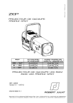
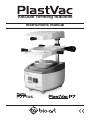
vacuum forming machine
instructions manual
Plus
INDEX
Introduction............................................................................................................................1
Packaging Contents...............................................................................................................1
Installation..............................................................................................................................1
Instructions for Use................................................................................................................2
Troubleshooting.....................................................................................................................4
Maintenance and Cleaning....................................................................................................4
Technical Specifications.........................................................................................................4
Warranty and Technical Assistance.......................................................................................5
European authorized representative......................................................................................5
INTRODUCTION
Plastvac P7 Bio-Art is multi-application equipment that, due to its easiness of use, has become
indispensable in laboratories and odontological offices.
PACKAGING CONTENTS
Plastvac P7 127 or 220VAC..........................................................................................(01 unit)
Power cable.................................................................................................................(01 unit)
Glass Beads................................................................................................................(250g)
Allen Wrench...............................................................................................................(01 unit)
Heating Unit Handle.....................................................................................................(01 unit)
Double-sided Cast rack................................................................................................(01 unit)
User Manual................................................................................................................(01 unit)
Sheets Display.............................................................................................................(01 unit)
Rotary Ring Handle......................................................................................................(01 unit)
Vacuum Activation Handle...........................................................................................(01 unit)
INSTALLATION
Plastvac P7 requires simple preparation and mounting before use.
• Handles: Thread the Vacuum Drive cables (the larger ones with M10 thread) by inserting the
longer cable on the right side, according to the scheme below. The other cables (the smaller
ones with M6 thread) should be threaded on the lower ring and the heating unit.
Note: For fixing function of the vacuum drive unit in the column, the action on the right cable
does not require much strength, tighten clockwise with a little effort, enough to keep the drive
unit in the heating position. To release the drive unit so that it slides into the column, just loosen
the cable by spinning it half turn counterclockwise.
• Installation: The equipment must be installed in a ventilated area, free from moisture and
excessive heat and must be placed on a flat table or bench. Do not place any material between
the supporting base and the bottom of the machine to not interrupt the air outlet and
compromise the equipment cooling.
• Electric Cable: Always check the correct equipment voltage before switching it on. The
protection grounding used must be according to standard NBR5410 (Brazil) or the current
standard in the importing country. Do not use the equipment on the same outlet where other
products are plugged through any connections. The voltage variation allowed for the
equipment power supply is ± 10% of the rated voltage.
1
INSTRUCTIONS FOR USE
Plastvac P7 enables two plasticizing processes: Conventional and Rotary.
Plus
Figure 01
01 – Heating unit handle
02 – Heating unit
03 – Vacuum activation handles
04 – Sheet support (Larger ring)
05 – Column
06 – Double-sided cast rack (tray for bead and flat surface)
07 – Vacuum chamber
08 – Main switch
09 – Shorter ring handle
10 – Rotary lock screw
11 – Lock side pins of shorter ring
12 – Shorter ring
13* – Digital Timer display
14* – Control Panel (digital timer)
(*) Only for PlastVac P7 PLUS model
CONVENTIONAL PLASTICIZING PROCESS
1. To start the process, raise the sheet support up to the upper limit and turn the vacuum activation
handle to the right in the clockwise direction to fasten the unit. Then turn the heating unit 180º in the
clockwise direction, leaving it completely facing the posterior part of the equipment.
2. Put the cast in the double-sided cast rack and then place the set in the vacuum chamber.
3. To position the sheet, turn the shorter ring in the anticlockwise direction and remove it, position the
sheet and invert the process to fasten it.
4. Return the heating unit to the initial position (aligned to the sheet support) and activate the main
switch to start the heating process (the red light of the main switch will go on).
5. Plasticizing Point: Due to the existence of several types of sheets, the plasticizing point is identified
by changes in the sheet, runoff or heating time. Generally the ideal point is observed by changes or
sheet runoff (10 to 12 mm).
6. Upon reaching the plasticizing point, turn the vacuum activation handle (right) in the anticlockwise
direction only enough to release sheet support and then lower the entire set completely through the
two handles until it is inserted in the vacuum chamber and the vacuum will start automatically.
7. Turn the heating unit again in the clockwise direction to the back part of the equipment and leave the
vacuum motor on until the conformation process is complete, which may take 10 to 20 seconds.
Warning: Do not leave the motor on for more than 1 minute to avoid overheating.
8. Turn off the main switch and allow the model to cool down.
9. Turn the shorter ring anticlockwise to release the model and remove it.
2
ROTARY PLASTICIZING PROCESS
1. The equipment leaves the factory with the sheet support locked to avoid accidental rotation in the
conventional process. It is necessary to loosen the screw with the 4 mm Allen wrench (item 10)
provided with the equipment only enough to release the set.
Attention: In this process, just place the double-sided cast rack into the vacuum chamber after the
heating process is complete.
2. After releasing the movement of the rotary system, follow the steps described in the conventional
system up to step 4 to heat one side of the sheet.
3. To heat the other side, turn the heating unit clockwise to the back part of the equipment and then
rotate the larger ring 180º in the anticlockwise direction until you hear a “click”, and with the other side
of the sheet exposed upwards return the heating unit to the initial position and wait for the heating of
this side of the sheet.
Attention: Never lower the sheet support when it is rotating.
4. Return the heating unit to the back part of the equipment and rotate the larger ring clockwise to the
initial process position. Leave the first heated side of the sheet to heat a bit more.
5. After heating is complete, follow the step 6 of the conventional process to conclude.
PlastVac P7-PLUS enables two plasticizing processes, conventional and Rotary, monitored by a
digital timer.
USING THE DIGITAL TIMER
1. Press the on/off button in the control panel to turn on the Digital Timer. Press set button once to
modify timer setting, then press adjust button repeatedly to change first digit of display. Press set
button to advance to next digit. Repeat until time is correct, then press set to confirm. A beep will signal
that the timer is set and ready for operation.
2. Return the heating unit to the initial position (aligned to the sheet support) and activate the main
switch to start the heating process. The red light of the main switch will go on and the timer will start to
countdown.
3. Once the timer reaches zero, it will begin beeping, indicating that the sheet is ready to be
thermoformed. Then, turn the vacuum activation handle (right) in the anticlockwise direction only
enough to release sheet support and lower the entire set completely through the two handles until it is
inserted in the vacuum chamber and the vacuum is started automatically.
4. Turn the heating unit again in the clockwise direction to the back part of the equipment and leave the
vacuum motor on until the conformation process is complete, which may take 10 to 20 seconds.
Warning: Do not leave the motor on for more than 1 minute to avoid overheating.
5. Turn off the main switch and allow the model to cool down.
6. The digital timer is activated (on/off) through the control panel, so when the main switch is turned
off, the digital timer continues on. The time entered is always memorized.
7. Turn the shorter ring anticlockwise to release the model and remove it.
REMARKS:
- Follow the manufacturer's instructions for adequate heating times of the sheets. Attention to the
sheet runoff since overheating can compromise the job and in extreme cases, the material can seep
in the vacuum motor, causing damages.
- For heating both sides of the sheet using the timer, keep in mind to set enough time to heat both sides
of the material according to the manufacturer's instructions.
- The sheet can be thermoformed at any time, before or after the timer reaches zero. Also, it can be
operated without the timer, thereby, the plasticizing point and sheet runoff should be done visually.
Consult our website for more information on the plasticizing processes and details of the equipment:
www.bioart.com.br
3
TROUBLESHOOTING
MAINTENANCE AND CLEANING
Always keep the equipment clean and free from moisture, especially the heating element located in
the heating unit. The heating element must not be touched by metallic tools or objects.
In case the heating element has to be replaced, it must be performed preferably by an authorized
technical service.
In case the power cable is damaged, it must be replaced by another with the same characteristics and
certifications.
The equipment column does not require lubrication; only keep it clean and free from dust and
residues.
To order spare parts, consult the exploded drawing and inform the code and nomenclature of the
desired part.
Fuse Replacement: Disconnect the power cable from the outlet before replacing the fuse.
It is highly recommended to purchase a similar fuse for replacement: Delayed actuation 5x20mm
(12A/250V for 127V machines and 7A/250V for 220V machines).
TECHNICAL SPECIFICATIONS
Voltages: Unique voltage 127V~ or 220V~ 50 / 60 Hz
Consumption Power: ~925W
Heating Power: 450 W
Motor Power: 1400 W
Sheet Dimensions: Up to 6 mm thick
Round sheet: from Ø120 to Ø134mm / Square sheet: From 120x120mm to 130x130mm
Dimensions: (WxDxH): 180 x 230 x 290 mm (without packaging) / 200 x 250 x 300 mm (with
packaging)
Weight: 4.500 kg (without packaging) / 5.235 kg (with packaging)
Pollution Degree: 2
Protection Degree: IPX1 (Protected against splatter)
Noise Level: Motor ~90 dB to 0.50M
4
WARRANTY AND TECHNICAL ASSISTANCE
Bio-Art Equipamentos Odontológicos Ltda., gives one (1) year warranty as from the date of purchase
of the product (purchase invoice). The warranty is granted exclusively by the authorized distributor
and includes any manufacturing defect, provided through repairing of the unit and limited to the
following requirements:
• The product was used correctly, according to the instructions provided in the present manual;
• The complaint is provided with the purchase invoice and registered within the warranty period,
followed by a report with description of the defect and serial number of the product;
The equipment is carefully handled, transported and stored;
• The cost of transportation (to and from) is paid by the customer.
The warranty excludes defects caused by:
• Natural wear of the parts;
• Misuse, hits and accidental falls;
• Inappropriate Transport;
• Repair by unauthorized personnel;
• Use not in compliance with the characteristics and purposes of the product;
• Wear by exposure to adverse conditions (moisture, intense cold or heat);
• Damages due to lack of cleaning or maintenance with unsuitable products.
In case of doubts, please consult the manufacturer:
EUROPEAN AUTHORIZED REPRESENTATIVE
Obelis s.a
Boulevard Général Wahis 53
1030 Brussels, BELGIUM
Tel: +(32) 2. 732.59.54
Fax: +(32) 2.732.60.03
E-Mail : [email protected]
5
Rev: CMAN1662 b - Jul/2015
Bio-Art Equipamentos Odontológicos Ltda
Rua Teotônio Vilela, 120 - Jd. Tangará - CEP 13568-000 - São Carlos - SP - Brazil
Tel. +55 (16) 3371-6502 -Fax +55 (16) 3372-5953
Home Page: www.bioart.com.br E-mail: [email protected]