1
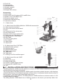
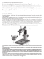
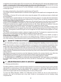
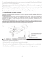
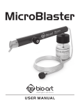
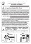
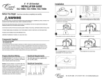
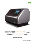
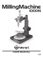
MillingMachine
1000N
intelligent solutions
USER MANUAL
CONTENTS
1. INTRODUCTION.............................................................................. 1
2. TECHNICAL SPECIFICATIONS...................................................... 1
3. PACKAGE CONTENTS................................................................... 1
4. INSTALLATION INSTRUCTIONS.................................................... 2
5. USE INSTRUCTIONS...................................................................... 3
6. SAFETY PRECAUTIONS................................................................ 5
7. MAINTENANCE AND CLEANING................................................... 5
8. SPECIAL STORAGE CONDITIONS................................................ 6
9. PROBLEMS AND SOLUTIONS....................................................... 7
10. SIMBOLOGY.................................................................................. 7
11. WARRANTY AND TECHNICAL ASSISTANCE.............................. 7
12. AUTHORIZED REPRESENTATIVE IN EUROPE.......................... 8
13. AUTHORIZED TECHNICAL ASSISTANCE................................... 8
1 - INTRODUCTION
The Bio-Art Milling Machine 1000N has the best market cost-benefit. The unique and consolidated
design makes the machine compact, robust and of high precision.
The Milling Machine 1000N head is equipped with a travel micrometric control and linear ball bearing,
the swing arm is mounted on precision radial bearings; the whole head structure, swing arm, column
and base are manufactured on CNC milling machines and constructed with latest generation materials,
allowing a handling with great sensitivity and high accuracy.
The unique head fastening adjustable system allows the use of various models of pens or micromotors
with body diameters from 20 to 30mm.
The surface treatment by anodizing process ensures the product a high level, durable and accurate
finishing.
Essential in the laboratory, the Bio-Art Milling Machine 1000N ensures high precision and versatility,
with the guarantee of a consolidated product on the market.
In addition to the product excellence, the Milling Machine 1000N has the following included
accessories: a 1040E rod, a set of Standart tips and a 1080 table, essential accessories for the most
various types of work. The 1080 table quickly and accurately allows the most various angles and
models fixing forms.
Before installing and using your Milling Machine 1000N, read all chapters of the user manual and if
there is still any doubt, please contact the company via our website www.bioart.com.br.
Read the instructions of this manual before operating the equipment.
2 - TECHNICAL SPECIFICATIONS
Span of the Milling Machine 1000N:......................................................................from 120 to 155mm
Adjustable fixation head:......................................................................................from Ø20 to Ø30mm
Maximum vertical stroke of the column:.....................................................................................85mm
Maximum vertical stroke of the head:.........................................................................................18mm
Control the vertical movement of the arm head:................................................................micrometric
Maximum radial movement of the arm:.........................................................................................200º
Maximum radial movement of the arm head:................................................................................180º
Base column lock:..........................................................................................................…mechanical
Arm lock:.............................................................................................................................mechanical
Capacity of 1080 table fixation:..................................................................................from 45 to 70mm
Radial movement of the 1080 table:.............................................................................................360º
Radial movement of the 1080 table model support:......................................................................360º
Max horizontal tilting of the 1080 table model support....................................................................30º
Lock of the 1080 table model.........................................................................mechanical clamps type
1040E Rod Body......................................................................................................................Ø23mm
Fixation capacity of the 1040E Rod grippers...........................................................Ø2,5 and Ø3,0mm
Shaft lock of the 1040E Rod...............................................................................................mechanical
Finishing the Milling Machine base:.........................................................................polycarbonate film
Milling Machine Dimensions (WxDxH):.........................173 x 223 x 400mm (maximum stroke height)
Packaging dimensions (WxDxH):..........................................................................260 x 300 x 440mm
Milling Machine 1000N weight with accessories without packaging:.......................................5,20 Kg.
Milling Machine 1000N weight with accessories and packaging..............................................5,84 Kg.
3 - PACKAGE CONTENTS
Set of the Milling Machine:
01 Base Model 1010;
01 Articulated Arm.
Set of standart tips:
01 Tip Nº 01;
01 Tip Nº 02;
1
01 Tip Nº 03;
01 Vertical knife;
01 Horizontal knife;
01 Graphite support;
01 Exploring tip;
02 Graphite Ø2 x 45mm
Accessories:
01 Table 1080;
01 Rod 1040E with 02 grippers Ø2.5 andØ3.0mm;
01 Metallic cover of the Base hole;
01 Protective plastic cover;
01 Micrometer adjustment key;
01 Instructions manual.
Fig.1
3.1 – Mains Items
3.1.1- Main items of the Milling Machine 1000N with accessories:
01- Head control micrometer;
02- Lever of the head vertical travel;
03- Arm;
04- Fixing knob of the column arm;
05- Arm locking lever;
06- Knob of the column vertical drive;
07- Protective cap of the base hole;
08- Milling Machine 1000N base;
09-1080 Table;
10- Column locking knob;
11- Rod 1040E;
12- Head clamp;
13- Head knob.
3.1.2- Main items of the 1080 Table.
01- Models fixation gramps;
02- Models support;
03- Models fixation knob;
04- Table locking knob;
05- Table body;
06- Table base;
07- Locking rod of the models support.
Fig.2
3.1.3- Main items of the rod 1040E.
01- Rod body;
02- Rod locking knob;
03- Shaft driving roller;
04- Fixation nut and gripper release;
05- Grippers Ø2.5 and Ø3.0mm;
06- Tips.
Fig.3
4 - INSTALLATION INSTRUCTIONS
The Milling Machine 1000N must be installed on a bench or a flat, leveled, vibration proof table, in a
ventilated location and free from humidity.
The moving parts of the Milling Machine 1000N consist of precision grinded columns, roller bearings
and ball linear bearing. For the perfect operation of these items, it is important that the location is free of
dust, moisture, or any other type of waste and heat sources.
For handling comfort and precision, the Milling Machine 1000N must have a minimum radius of 0,50
meters exclusive free space.
The Milling Machine 1000N base has no fastening system on the bench, just anti-slip rubber feet.
2
Therefore, make sure that the contact of the feet with the bench is not sliding. Under no circumstances
fix the Milling Machine 1000N base with cleats or similar, because this action can change the milling
machine accuracy.
Important:
Make sure the pens or micromotors body to be used on the Milling Machine 1000N, is within the
characteristics supported by the head, i.e., with diameters from 20 to 30mm. Otherwise the pen,
micromotor or any other accessory fixation will be deficient and may cause damage to the fixation
system of the articulated arm head. THE PEN OR MICROMOTOR FACES WILL HAVE TO BE
PARALLEL.
5 - USE INTRUCTIONS
5.1- Adjustment and fixation of the accessories on the Milling Machine 1000N head.
For better understanding of this topic, be guided through the items of Figures 01.
With the arm locked with the lever (05), loosen the knob (13) by rotating two turns counter-clockwise
and move it to the left to release the clamp.
Open the head (12) clamp as shown in Figure 04B and turn in both directions to adjust the distance
between the clamp and the head, according to the need of the accessory to be used (Rod, Pen or
Micromotor).
To make sure that the distance between the clamp and the head is correct, place the accessory in the
appropriate place and close the clamp to touch the accessory checking their parallelism.
For fixing the accessory, rotate manually the knob (05) without forcing clockwise, as shown in Figure
04C, until the accessory is fixed and without any clearance.
13
14
DYNAMICS A:
RELEASE THE HEAD KNOB
Fig.4
FIXATION KNOB
DYNAMICS C:
TIGHT THE KNOB ON
THE CLAMP AT THE
HEAD
ROD 1040E
MICROMOTOR
PEN
05
DYNAMICS B:
ADJUST THE DISTANCE
BETWEEN THE CLAMP
AND THE HEAD
ONLY TIGHT MANUALLY.
NEVER USE ANY TYPE OF TOOL.
ADJUST THIS DISTANCE ACCORDING TO THE MICROMOTOR BODY DIMENSIONS
5.2- Precision vertical movement of the head.
For better understanding of this topic, be guided through the items of Figures 01.
With the arm locked with the lever (05) arm, adjust the head desired vertical stroke using the micrometer
(01), turning left or right using the graduation on the micrometer body.
The head allows the adjustment of zero stroke (locked) up to 18mm. Over this dimension, does not
exceed the rotating drum of the micrometer.
The vertical movement of the head is done through the lever (02), pressed down with the finger with
automatic spring return, limited to the weight of the accessory.
Because the head is built with low friction linear ball bearing, if desired, the vertical movements can also
be done by holding the accessory and respecting the fragility of each situation.
5.3- Radial movements of the arm and head.
For better understanding of this topic, be guided through the items of Figures 01.
To lock or release the radial movements of the arm and head, rotate the arm (05) lock lever, respectively
clockwise or counterclockwise.
The Figure 05 below illustrates the dynamics of the possibilities of radial movements of the arm and
head.
3
5.4- Vertical movement of the Milling Machine column.
For better understanding of this topic, be guided through the items of Figures 01.
The column of the Milling Machine 1000N can be moved vertically up to 85mm using the knob (06).
For this to be done, unlock the column using the knob (10) by turning it a half turn counter-clockwise. To
lock the column, rotate the same knob (10) clockwise until you feel resistance.
At the ends of stroke (upper or lower) a resistance will occur on the knob (06). When this resistance
appears, do not apply force on the knob.
The use of the knobs (06 and 10) of the column, must only be done manually, under no circumstances
use any type of tool.
5.5- Using the 1080 Table.
The Milling Machine 1000N base (08) has a threaded fitting as shown in Figure 06, where the 1080
Table is adapted.
Before the Table installation or removal on the sealer base, make sure that the table locking knob (04) is
tight, thereby locking the radial movement of the Table.
To install the 1080 Table, fit the existing ledge at the base of the Table (06) on the proper fit of the Milling
Machine 1000N base and turn the whole table clockwise until resistance occurs at the end of the thread.
To remove the Table from the Milling Machine 1000N base, proceed in reverse, turning manually the
whole table in the counterclockwise direction, always being aware that the Table knot (04) is tight.
If the 1080 Table is not fixed during use, we recommend protecting the Milling machine base fit with the
protective cap (07), supplied with the product.
To fix and remove the 1080 table, do it manually, under no circumstances use any type of tool.
Fig.5
The fixation of a model on the 1080 table is done using the models support (02) and the clamps action
(01).
The thigh is similar to a bench, done through the knob (03). Turning to the right it tights and to the left it
releases the model.
The 1080 Table is versatile and allows a multitude of movements according to the work to be performed.
The model support (02) in addition to the 360º radial movement, also enables horizontal tilting up to 30º
throughout the radial extent of movements. For this to be possible just release the models support using
the lever (07).
The lever (07) has the function to lock and to release the models support anywhere along its movement.
Push the lever (07) to the right to lock and to left to release the models support. Follow the instruction
(release and lock), printed on the label on the 1080 table body.
4
In addition to the models support (02) movements, the 1080 table body (05) can also be radially moved
on 360° on its base (06). For this to be possible, just release the Table body using the knob (04), turning
a half turn to the left and to lock rotate the same knob (04) to the right until it stops.
To use the knob (04) and the lever (07) of the 1080 table, only do it manually, under no circumstances
use any type of tool.
For better understanding, be guided through the items of Figure 03.
The 1040E rod has a manual rotation movement of the high precision shaft and it is designed with roller
bearings.
The fixation of the tips (06) on the rod is done using the gripper (05), providing a simple, reliable and
accurate fixation.
The 1040E Rod is supplied with two 2,5 and 3,0mm diameter grippers, only tips with these diameters
can be used. Never use tips with diameters different from 2,5 and 3,0mm, as this will damage the clamp
and hence the fixation will be defective.
To fix or release the gripper tips, grasp the shaft roller (03) with the fingers of your left hand, and with the
fingers of your right hand turn the gripper nut (04) to the left to release the tip and to the right to lock it.
To release the tips from the gripper, just half turn the nut (04). Even with the nut released, it may be
necessary a slight action toward the inside of the gripper to completely release the tip.
To change the grippers from 2,5 to 3,0mm, or reverse, completely remove the nut (04) by turning it to the
left, then carefully remove the gripper from the inside of the shaft and perform the change. Put the nut
(04) back, turning three turns to the right, but do not tight the nut (04) with the empty gripper as it may
damage it.
The 1040E rod shaft can be locked or released using the knob (02). To release turn a quarter turn to the
left and to fix turn right until you feel a resistance and the locking of the shaft.
When acting on the gripper nut (04), fixing or releasing tips, make sure that the 1040E rod shaft is
released using the knob (02).
The fixation of the 1040E Rod on the head arm of the Milling Machine 1000N must be done in the region
(01) of the rod body, 23mm diameter location, just above the knob (02), as seen in Figure 03.
6 - SAFETY PRECAUTIONS
1- All 1000N Milling Machine commands and knobs are designed for handling, never use any kind of
tool.
2- In case of moisture, mainly on the Milling Machine moving parts or its accessories, immediately clean
and dry with a dry cloth as best as possible, under no circumstances use compressed air for cleaning.
3- Take care when handling the horizontal and vertical knives, their sharp edges can cause accidents.
4- When using high speed micromotors, follow the manufacturer's safety recommendations, including
those related to commands and electrical cords that may come into contact with the metal parts of the
milling machine.
High speed pens and micromotors must be balanced, therefore the excess vibration can affect the
Milling Machine 1000N accuracy and compromise the fixation of some important components.
5- It is indispensable to use goggles for any kind of work on the Milling Machine 1000N.
6- The Milling Machine 1000N base is coated with a polycarbonate film, although tough, it is essential to
be careful when handling metal parts and tools, as well as chemicals on it, avoiding any surface
damage.
7 - MAINTENANCE AND CLEANING
7.1- Cleaning and lubrication.
The Milling Machine 1000N is a high precision machine. Its main moving parts do not require periodic
adjustments or maintenance, thus any maladjustment, looseness or operating difficulties should be
referred to the Authorized Technical Assistance. Do not attempt to make repairs or adjustments not
cited in this chapter under the risk of endanger the accuracy of the product.
To clean the Milling Machine 1000N, the 1080 table and the 1040E rod, do not use chemicals or
solvents, only use a soft brush and a dry cloth. Under no circumstances do the cleaning using
compressed air.
5
For protection against dust and moisture, we recommend covering the Milling Machine 1000N with
protective cover included in the packaging.
Only two items require periodic lubrication: the Milling Machine 1000N column and the linear guide rail
of the 1060 Arm head.
For the column lubrication, compress the bellows and put a small amount of common grease spreading
on the entire column, then readjust the bellows.
To lubricate the linear guide rail, put a few drops of light oil spreading on its visible part, under the arm
head.
The checking of the need for lubrication is visual and according to the utilization frequency.
7.2- Adjustment of the micrometer graduation:
Due to the characteristic of the micrometer (01) or due to improper use of the head, an offset of your
graduation may occur.
To make sure of this occurrence, turn the micrometer until the vertical stroke end of the head (no
movement) and make sure the drum "zero" graduation coincides with the central risk of the shaft
graduation, see figure 07. If this coincidence does not occur, the micrometer graduation must be
adjusted as follows:
- With the micrometer (01) at the end of the head stroke (head with no vertical movement), put the
micrometer key on the shaft checking the key locking pin fit in the corresponding hole of the micrometer
body and carefully rotate the key left or right, as needed, to exactly coincide the rotating drum zero
graduation with the center line of the micrometer shaft graduation. See Figure 07.
Fig.6
ROTATING DRUM GRADUATION
GRADUATION 0 TO 18 OF THE
FIXED SHAFT
CORRECT ADJUSTMENT
INCORRECT ADJUSTMENT
8 - SPECIAL STORAGE CONDITIONS
- Store in a cool, dry and dust free location;
- Far from chemicals, sources of moisture, heat and direct sunlight;
- When not in use, keep the Milling Machine 1000N protected with a plastic protective cover (included);
- If the Milling Machine 1000N remains unused for a long period, store it in its original package.
6
9 - PROBLEMS AND SOLUTIONS
10 - SIMBOLOGY
Serial Number
Catalog Number
Consult Instructions for
Use
Authorized Representative
In the European Community
Date of Manufacture
Manufacturer
11 - WARRANTY AND TECHNICAL ASSISTANCE
BIO-ART Equipamentos Odontológicos Ltda., gives a 01 (one) year warranty for this product from its
date of purchase. This warranty covers any manufacturing defect, except for the polycarbonate film
coating of the Milling Machine 1000N base. The warranty will be solely provided by the authorized
dealer on repair of the equipment that is conditional upon the following requirements:
a) That the product has been properly used in accordance with the provided instructions. We remember
that the Milling Machine 1000N must be handled, transported and stored with care. The fall or knocks on
the equipment will characterize misuse, resulting in the loss of this Warranty.
b) That the claim is sent together with the product purchase invoice and registered within the warranty
period, and with a report including the description of the defect and the product serial number.
7
Limits of Warranty:
• Natural wear of the parts;
• Defects due to the improper use or storage of the product;
• Inadequate transportation;
• Non-compliance use with the characteristics and purposes of the product, it is the reason why this
manual must be read with great attention;
• Damage due to exposure to adverse conditions (humidity, intense heat, chemical interaction, etc.);
• Cleaning and/or disinfecting with unsuitable products.
To take advantage of this warranty in the domestic market (Brazil), the consumer will be in charge to
send the product to the address below or to the nearest Bio-Art Authorized Technical Assistance. Look
for the Authorized Technical Assistance offices on our website: www.bioart.com.br.
BIO-ART EQUIPAMENTOS ODONTOLÓGICOS LTDA.
Rua Teotônio Vilela, 120 – Jardim Tangará – CEP 13568-000 – São Carlos – SP – Brasil
Tel. +55 (16) 3371-6502 – Fax +55 (16) 3372-5953 – www.bioart.com.br
CNPJ 58.538.372/0001-56 – Insc. Estadual 637.034.447.113
For other countries, the warranty is solely provided by the authorized dealer (legal importer).
12 - AUTHORIZED REPRESENTATIVE IN EUROPE
Obelis s.a.
Boulevard Général Wahis 53 - 1030 Brussels, BELGIUM
Tel: +(32) 2.732.59.54 - Fax: +(32) 2.732.60.03
E-mail: [email protected]
The information provided in this manual is subject to changes that may be made without notice.
13 - AUTHORIZED TECHNICAL ASSISTANCE
For your safety, the technical assistance of this product must be performed by authorized
persons/companies. Look for the Authorized Technical Assistance offices on our website
www.bioart.com.br.
8
Rev: CMAN1507 - Fev/2014
soluções inteligentes
Rua Teotônio Vilela, 120 - Jd. Tangará - CEP 13568-000 - São Carlos - SP - Brasil
Tel. +55 (16) 3371-6502 - Fax +55 (16) 3372-5953
www.bioart.com.br