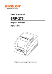
1
Tapped Density Tester
Operator’s Manual
Agilent Technologies
Notices
© Agilent Technologies, Inc. 2011
Warranty
No part of this manual may be reproduced
in any form or by any means (including
electronic storage and retrieval or translation into a foreign language) without prior
agreement and written consent from Agilent Technologies, Inc. as governed by
United States and international copyright
laws.
The material contained in this document is provided “as is,” and is
subject to being changed, without
notice, in future editions. Further,
to the maximum extent permitted
by applicable law, Agilent disclaims
all warranties, either express or
implied, with regard to this manual
and any information contained
herein, including but not limited to
the implied warranties of merchantability and fitness for a particular purpose. Agilent shall not be
liable for errors or for incidental or
consequential damages in connection with the furnishing, use, or
performance of this document or of
any information contained herein.
Should Agilent and the user have a
separate written agreement with
warranty terms covering the material in this document that conflict
with these terms, the warranty
terms in the separate agreement
shall control.
Manual Part Number
70-9069
Edition
Rev A, April 2011
Printed in USA
Agilent Technologies, Inc.
3501 Stevens Creek Blvd.
Santa Clara, CA 95052 USA
(Technical Data) and 12.212 (Computer
Software) and, for the Department of
Defense, DFARS 252.227-7015 (Technical Data - Commercial Items) and DFARS
227.7202-3 (Rights in Commercial Computer Software or Computer Software
Documentation).
Safety Notices
CAUTION
A CAUTION notice denotes a
hazard. It calls attention to an
operating procedure, practice, or
the like that, if not correctly performed or adhered to, could result
in damage to the product or loss
of important data. Do not proceed
beyond a CAUTION notice until
the indicated conditions are fully
understood and met.
WA RNING
Technology Licenses
The hardware and/or software described in
this document are furnished under a
license and may be used or copied only in
accordance with the terms of such license.
Restricted Rights Legend
U.S. Government Restricted Rights. Software and technical data rights granted to
the federal government include only those
rights customarily provided to end user
customers. Agilent provides this customary commercial license in Software and
technical data pursuant to FAR 12.211
A WARNING notice denotes a
hazard. It calls attention to an
operating procedure, practice,
or the like that, if not correctly
performed or adhered to, could
result in personal injury or
death. Do not proceed beyond a
WARNING notice until the
indicated conditions are fully
understood and met.
Tapped Density Tester Operator’s Manual
Contents
Figures
1
Safety
7
9
Electrical Hazards 10
Warning
11
Caution
11
Note
11
Information Symbols
General 13
WEEE Directive
2
Introduction
12
14
15
Available Configurations
16
Conventions Used in this Manual
USP Suitability Test
17
USP Physical Parameters
3
16
17
Setting Up the Tapped Density Tester
Initial Setup 20
Unpacking Procedure
Clearance
21
20
Power Cord Connection
21
Connecting the Printer
22
Mounting Platforms and Cylinders
Setting the Date and Time
Tapped Density Tester Operator’s Manual
19
23
23
3
Contents
Hidden Key Functions
4
24
Operating the Tapped Density Tester
25
Operating the Tapped Density Tester Without a Printer
Running a Test Without the Optional Printer 26
Stopping a Test
27
Operating the Tapped Density Tester with a Printer
Configuring for the Number of Cylinders Used
Running a Test
29
Stopping a Test
30
5
Troubleshooting and Maintenance
Maintenance
32
Periodic Maintenance
26
28
28
31
32
Report Center Impact Printer
33
Installing the Cartridge Ribbon 33
Replacing the Paper Roll
34
Toggling Your Printer Online 35
Printer Self Test
35
Printer Configuration 36
Fuse Replacement
38
Troubleshooting
39
Cam Adjustment
40
6
Service and Warranty
43
Service and Warranty Information
44
Exclusions and Limitations 44
Obtaining Warranty Service 44
Warranty Limitations 45
Exclusive Remedies
45
4
Tapped Density Tester Operator’s Manual
Contents
Index
Tapped Density Tester Operator’s Manual
47
5
Contents
This page was intentionally left blank, except for this message.
6
Tapped Density Tester Operator’s Manual
Figures
Figure 1. Cam Diagram
Tapped Density Tester Operator’s Manual
41
7
Figures
This page was intentionally left blank, except for this message.
8
Tapped Density Tester Operator’s Manual
Tapped Density Tester
Operator’s Manual
1
Safety
Electrical Hazards 10
WEEE Directive 14
The Tapped Density Tester has been carefully designed so that when
used properly you have an accurate, fast, flexible, and safe instrument.
If the equipment is used in a manner not specified by the manufacturer,
the protection provided by the equipment may be impaired.
The Tapped Density Tester is operated in conjunction with equipment
that uses aqueous liquids. Unskilled, improper, or careless use of this
instrument can create shock hazards, fire hazards, or other hazards
which can cause death, serious injury to personnel, or severe damage to
equipment and property.
Information on safety practices is provided with your instrument and
operation manuals. Before using your instrument or accessories, you
must thoroughly read these safety practices.
Observe all relevant safety practices at all times.
Agilent Technologies
9
1
Safety
Electrical Hazards
The Tapped Density Tester contains electrical circuits, devices, and
components operating at dangerous voltages. Contact with these
circuits, devices, and components can cause death, serious injury, or
painful electric shock.
Panels or covers that are retained by fasteners which require the use of a
tool for removal may be opened only by Agilent-trained,
Agilent-qualified, or Agilent-authorized service engineers. Consult the
manuals or product labels supplied with the Tapped Density Tester to
determine which parts are operator-accessible.
Application of the wrong supply voltage, connection of the instrument
to an incorrectly wired supply outlet, or lack of proper electrical
grounding can create a fire hazard or a potentially serious shock hazard
and could seriously damage the instrument and any attached ancillary
equipment.
Always use a three-wire outlet with ground connection which is
adequately rated for the load. The installation must comply with local,
state, and federal safety regulations.
Do not connect the instrument to the main power supply until you have
made sure that the operating voltage is correctly set for the main power
supply in the specific outlet in your laboratory to which the equipment
will be connected.
10
Tapped Density Tester Operator’s Manual
Safety
1
Warning
WA RNING
A ‘Warning’ message appears in the manual when failure to observe
instructions or precautions could result in death or injury.
Read all warnings and cautions carefully and observe them at all times.
Caution
CAUTION
A ‘Caution’ message appears in the manual when failure to observe
instructions could result in damage to equipment (Agilent supplied and /
or other associated equipment).
Note
NOT E
A ‘Note’ appears in the manual to give advice or information.
Tapped Density Tester Operator’s Manual
11
1
Safety
Information Symbols
I
Switches main power on
0
Switches main power off
Indicates single-phase alternating current
Indicates the product complies with the
requirements of one or more European Union
(EU) directives
Indicates specific equipment meets
consensus-based standards of safety to provide
assurance, required by OSHA, that these
products are safe for use in the workplace for
North America
Indicates that this product must not be disposed
of as unsorted municipal waste
12
Tapped Density Tester Operator’s Manual
Safety
1
General
CE Compliant Products
The Tapped Density Tester has been designed to comply with the
requirements of the Electro-magnetic Compatibility (EMC) Directive
and the Low Voltage Directive (LVD) of the EU.
Agilent, Inc. has confirmed that each product complies with the relevant
directives by testing a prototype against the prescribed European Norm
(EN) standards.
Proof that a product complies with the directives is indicated by:
• the CE marking appearing on the rear of the product.
• the documentation package that accompanies the product containing
a copy of the declaration of conformity. This declaration is the legal
declaration by Agilent, Inc. that the product complies with the
directives and also shows the EN standards to which the product was
tested to demonstrate compliance. The declaration of conformity is
signed by the representative of the manufacturing plant.
cTUVus - U.S. and Canadian Product Approvals
The Tapped Density Tester has been designed to comply with North
American safety requirements.
This product has been tested and certified for the North American
market by TUV Rheinland of North America, Inc. The TUVus mark
signifies that this product has been tested to U.S. standards and certified
for the U.S. market. The cTUV mark signifies that this product has been
tested to Canadian standards and certified for the Canadian market.
When the two marks are coupled, the cTUVus mark signifies that this
product has been tested to standards and certified for both markets.
Tapped Density Tester Operator’s Manual
13
1
Safety
WEEE Directive
All Agilent products that are subject to the WEEE directive shipped
after August 13, 2005 are compliant with the WEEE marking
requirements. Such products are marked with the “crossed out wheelie
bin” WEEE symbol shown on page 12 in accordance with European
Standard EN 50419.
This symbol on the product or on its packaging indicates that this
product must not be disposed of as unsorted municipal waste. The
separate collection and recycling of your waste equipment at the time of
disposal will help to conserve natural resources and ensure that it is
recycled in a manner that protects human health and the environment.
For more information on collection, reuse, and recycling systems,
please contact your local/regional waste administration, your local
distributor, or Agilent, Inc.
14
Tapped Density Tester Operator’s Manual
Tapped Density Tester
Operator’s Manual
2
Introduction
Available Configurations 16
Conventions Used in this Manual
USP Suitability Test 17
USP Physical Parameters 17
16
The Tapped Density Tester provides a standardized, reproducible
method for measuring the tapped or bulk density of powdered,
granulated, or flaked materials. This is important since changes in the
tapped density of raw materials can affect their performance during the
manufacturing process. For example, powders which do not meet the
normal incoming QC tapped density specification might tend to clog
tablet presses and disrupt the manufacturing process.
WA RNING
The Tapped Density Tester contains electrical circuits, devices,
and components operating at dangerous voltages. Contact with
these circuits, devices and components can cause death, serious
injury, or painful electric shock.
CAUTION
Panels or covers that are retained by fasteners which require the use
of a tool for removal may be opened only by Agilent-trained,
Agilent-qualified, or Agilent-authorized service engineers.
Agilent Technologies
15
2
Introduction
Available Configurations
The Tapped Density Tester is available in single-platform and
dual-platform models. Standard configurations include one or two 100
mL funnel-top cylinders and platforms as appropriate. Optionally, 10,
25, 50, 250, and 500 mL cylinders and platforms are available. All can
be interchanged with no mechanical modification to the instrument.
In addition to the standard USP design with a drop of 14 ± 2 mm, an
ASTM version is also available with a 3 mm ± 10% drop, no cylinder
rotation, and a 250 taps per minute nominal speed. This version is used
for industrial applications such as chemicals and powdered metals.
Conventions Used in this Manual
• Items you are asked to press are in bold. For example, “press H on
the keypad”.
NOT E
16
Remember to return the warranty card supplied with this manual.
Completing and returning the card ensures your right to protection
under the terms and conditions of your warranty. It also enables us to
better assist you in the event of any problems. Additionally, it
guarantees you will be informed of any issues that arise concerning your
equipment, such as upgrades, retrofits, or regulatory changes.
Tapped Density Tester Operator’s Manual
Introduction
2
USP Suitability Test
Before initial use of any dissolution instrument, and periodically
thereafter, the USP requires that you run an Performance Verification
Test with USP Dissolution Calibrators. These calibrator tablets are
available from the USP at the following address:
USP-NF Reference Standards
12601 Twinbrook Parkway
Rockville, MD 20852
301.881.0666
Complete instructions come with the calibrator tablets. Calibration tests
can be very sensitive to factors such as paddle or vessel misalignment,
vessel shape, vibration of the system, age of the calibrator tablets and
reference standards, and many other factors.
USP Physical Parameters
In addition to the Apparatus Suitability Test, several physical
parameters must be monitored, such as shaft wobble, centering, speed,
and shaft verticality. A Certificate of Inspection is included with all
dissolution apparatus. Contact the Dissolution Systems Service
Department for more information on USP Physical Parameters.
Tapped Density Tester Operator’s Manual
17
2
Introduction
This page was intentionally left blank, except for this message.
18
Tapped Density Tester Operator’s Manual
Tapped Density Tester
Operator’s Manual
3
Setting Up the Tapped Density Tester
Initial Setup 20
Power Cord Connection 21
Setting the Date and Time 23
Hidden Key Functions 24
Agilent Technologies
19
3
Setting Up the Tapped Density Tester
Initial Setup
Complete the following sections to initially set up the Tapped Density
Tester and all other system components.
Unpacking Procedure
Complete these steps to safely unpack and set up your equipment:
1 Open each carton and check the contents for damage which may
have occurred during shipping. Shipping damage rarely occurs, but if
it does contact both the carrier who delivered the instruments and the
Dissolution Systems Service Department. Though claims for damage
should be filed with the carrier, we can help you file a claim.
2 Carefully remove the Tapped Density Tester base unit from the
shipping carton. Place it on a clean, dry, level area of your benchtop
within four feet (122 cm) of a grounded electrical outlet.
WA RNING
The electrical connection at the back of the Tapped Density
Tester is the primary disconnect for the instrument. The tester
should be positioned to allow accessibility to the power cord for
easy disconnection.
3 Ensure the power is off.
WA RNING
Before plugging the Tapped Density Tester into any power
outlet, ensure the instrument is properly configured for the
voltage provided. Check the serial number tag on the rear panel
of the instrument to confirm the voltage requirement.
4 Connect the power cord (found in the instrument accessory kit)
between the receptacle on the rear panel and an electrical outlet of
the appropriate voltage.
20
Tapped Density Tester Operator’s Manual
Setting Up the Tapped Density Tester
3
5 Turn on the Tapped Density Tester. The LED on the front panel
illuminates. If not, ensure the unit is securely plugged in and there is
power at the outlet. If the unit still fails to respond, see
“Troubleshooting” on page 39 or call the Dissolution Systems
Service Department.
Clearance
1 Prepare the area where the equipment is to be located.
2 Ensure a minimum clearance of 35 cm above the unit and 10 cm at
the rear and on both sides of the Tapped Density Tester.
Approximately 50 x 60 cm total bench space is required. For the
optional Acoustic Cabinet, 84 x 44 x 46 cm of bench space is
required.
3 Orient the Tapped Density Tester and all other system components
appropriately.
Power Cord Connection
1 Before connecting the power cord(s), verify the correct voltage has
been selected.
2 Ensure the main power switch in the rear panel AC power connector
is in the off position.
3 Connect or verify connection of the female end of the AC power cord
into the power connector on the Tapped Density Tester rear panel.
4 Plug the cord into an AC electrical supply of the same voltage as
stamped on the instrument’s identification tag.
Tapped Density Tester Operator’s Manual
21
3
Setting Up the Tapped Density Tester
Connecting the Printer
If your unit is equipped with the optional Report Center Printer,
complete the following steps to connect it to your Tapped Density
Tester:
NOT E
If your Tapped Density Tester came equipped with a Star SP500-series
printer, please refer to the SP500 Series User’s Manual for setup
instructions.
1 Remove the printer from the shipping carton.
2 Place it on a clean, dry, level area of your benchtop to the left of your
Tapped Density Tester.
3 Connect the printer cable between the rear of the printer and the port
on the right-side panel of the Tapped Density Tester.
4 Connect the AC power adapter between the jack on the rear of the
printer and an electrical outlet of the appropriate voltage.
Toggle the printer online by pressing the printer toggle switch to the
OnLine / Off Line position. The Ready LED illuminates. If not, ensure
the printer is securely plugged in and there is power at the outlet. If the
device still fails to respond, see “Troubleshooting” on page 39 or call
the Dissolution Systems Service Department.
22
Tapped Density Tester Operator’s Manual
Setting Up the Tapped Density Tester
3
Mounting Platforms and Cylinders
Complete the following steps to mount platforms and cylinders:
1 Insert the shafts on the cylinder platforms into the sleeves on top of
the unit. The cylinder platforms simply drop into the sleeves and
should be free to move up and down.
NOT E
Each side of the dual Tapped Density Tester is calibrated to the
corresponding platform. Ensure the correct platform is placed into the
proper sleeve (left and right).
2 Slide the bases of the graduated cylinders onto the cushioned
platforms. The base of each cylinder is held under the platform and
secured by the pair of spring clips.
Setting the Date and Time
The Tapped Density Tester comes equipped with a battery-backed up
clock which stores the date and time. If your unit is equipped with the
Report Center Printer, the date and starting time print on the report. If
applicable, complete the following steps to set the date and time:
1 Press SET CLOCK. The current date (in mm/dd/yy format) and
time (in 24-hour format) display alternately.
2 To accept the current date and time, press CLEAR. The test duration
displays and no further action is required.
To change the date and time, press SET CLOCK again. The date
displays in mm/dd/yy format.
3 To accept the date as it displays, press ENTER. The time displays in
24-hour format.
To change the date, enter the new value and press ENTER. The time
displays in 24-hour format.
4 To accept the time as it displays, press ENTER. The test duration
displays.
To change the time, enter the new value and press ENTER. The test
duration displays.
Tapped Density Tester Operator’s Manual
23
3
Setting Up the Tapped Density Tester
Hidden Key Functions
Hidden keys can be accessed only when the Printer On LED is not
illuminated, indicating that the printer is disabled, and the motor is
running. Toggle PRINT to enable or disable the printer. In order to
enable the PRINT key, press CLEAR > 9. In the following table,
CLEAR > (function) indicates you should press CLEAR and then the
function key.
Table 1
24
Hidden Key Functions
Key Sequence
Function
CLEAR > 1
Use this key sequence to indicate a single cylinder.
CLEAR > 2
Use this key sequence to indicate dual cylinders.
CLEAR > 6
Use this key sequence to enable the PCB display.
CLEAR > 7
Use this key sequence to indicate the Tapped Density Tester.
CLEAR > 9
Use this key sequence to enable the PRINT key.
CLEAR > 0
Use this key sequence to disable the PRINT key.
Tapped Density Tester Operator’s Manual
Tapped Density Tester
Operator’s Manual
4
Operating the Tapped Density Tester
Operating the Tapped Density Tester Without a Printer 26
Operating the Tapped Density Tester with a Printer 28
Agilent Technologies
25
4
Operating the Tapped Density Tester
Operating the Tapped Density Tester Without a Printer
WA RNING
The Tapped Density Tester produces excessive noise levels.
During operation consider wearing approved hearing protection
devices or operating the unit in the optional acoustic cabinet.
If your unit is equipped with a printer, see “Operating the Tapped
Density Tester with a Printer” on page 28.
Running a Test Without the Optional Printer
Complete the following steps to run a test using a Tapped Density Tester
not equipped with a Report Center Printer:
1 Ensure the PRINT key is disabled. See “Hidden Key Functions” on
page 24 for instructions on how to disable the PRINT key.
2 Select the mode of operation, either timer or counter, by pressing
TIME COUNT. This key toggles the unit between the two operating
modes. The Timer LED illuminates to indicate the timer option is
selected. The Counter LED illuminates to indicate the counter option
is selected.
3 Enter either the number of taps (up to 999,999) or the time duration
(in hh:mm:ss format) as applicable and press ENTER. Once entered,
the test duration is saved by the unit and does not need to be reset
unless you want to change it. To change the duration, enter the new
value and press ENTER.
4 Pass the product through a number 18 sieve (1.00 mm sieve
opening), if appropriate, and weigh the product for each cylinder
separately.
5 Load the product into the cylinders and level it without compacting,
if necessary.
6 Press START STOP to begin. The time duration or number of taps
count down on the display screen and the test stops automatically
when 0 is reached. The display automatically resets to the original set
value preparing the instrument for the next test.
26
Tapped Density Tester Operator’s Manual
Operating the Tapped Density Tester
4
7 To calculate the tapped density, use the following equation:
initial weight
tapped density = ------------------------------final volume
Stopping a Test
When running a test on a Tapped Density Tester without a printer, you
can stop the test by pressing START STOP. The cylinders stop
immediately and the display returns to the original test length setting.
Tapped Density Tester Operator’s Manual
27
4
Operating the Tapped Density Tester
Operating the Tapped Density Tester with a Printer
WA RNING
The Tapped Density Tester produces excessive noise levels.
During operation consider wearing approved hearing protection
devices or operating the unit in the optional acoustic cabinet.
If your unit is not equipped with a printer, see “Operating the Tapped
Density Tester Without a Printer” on page 26.
Configuring for the Number of Cylinders Used
Complete the following steps to configure your printer-equipped
Tapped Density Tester for the number of cylinders in use:
1 Ensure the PRINT key is enabled. See “Hidden Key Functions” on
page 24 for instructions on how to enable the PRINT key.
2 Ensure the Printer On LED is not illuminated. If the LED is
illuminated, press PRINT to disable the printer.
3 Press START STOP. The instrument begins tapping.
4 Use the following keystroke combination depending on the number
of cylinders you wish to specify.
• CLEAR > 1 for one cylinder
• CLEAR > 2 for two cylinders
If you select two cylinders, you are prompted for two weights when you
begin the test and two volumes at the end of the test.
5 Press START STOP. The instrument stops tapping.
6 Press PRINT to enable the printer. The Printer On LED illuminates.
The next time you press START STOP, with the printer enabled, the
appropriate number of initial weights and final volumes are
requested based on the number of cylinders specified.
28
Tapped Density Tester Operator’s Manual
Operating the Tapped Density Tester
4
Running a Test
If your Tapped Density Tester is equipped with the optional Report
Center Printer, you can print a report at the end of each test to document
the date, starting time, mode selected and set values, initial weights,
final volumes and tapped densities. If the Printer On LED is illuminated,
the printer is enabled. Press PRINT to enable or disable the printer.
Complete the following steps to operate your Tapped Density Tester
with Report Center Printer:
1 Ensure the printer is enabled. When the printer is enabled, the Printer
On LED illuminates.
2 Toggle the printer online by pressing the printer toggle switch to the
OnLine / Off Line position. The Ready LED illuminates.
3 Select the mode of operation, either timer or counter, by pressing
TIME COUNT. This key toggles the unit between the two operating
modes. The Timer LED illuminates to indicate the timer option is
selected. The Counter LED illuminates to indicate the counter option
is selected.
4 Enter either the number of taps (up to 999,999) or the time duration
(in hh:mm:ss format) as applicable and press ENTER. Once entered,
the test duration is saved by the unit and does not need to be reset
unless you want to change it. To change the duration, enter the new
value and press ENTER.
5 Pass the product through a number 18 sieve (1.00 mm sieve
opening), if appropriate, and weigh the product for each cylinder
separately.
6 Load the product into the cylinders and level it without compacting,
if necessary.
7 Press START STOP. You are prompted to enter the initial weight (in
grams) of the product in the cylinder. Up to two weights can be
entered depending on the number of cylinders used (see
“Configuring for the Number of Cylinders Used” on page 28). The
following is a summary of what displays after you press START
STOP but before the cylinders begin to tap:
Tapped Density Tester Operator’s Manual
29
4
Operating the Tapped Density Tester
• The numeral 1 displays on the display screen alternating with the
last initial weight entered for the product in cylinder 1. Press
ENTER to accept the displayed value or enter the new initial
weight and press ENTER. If you have indicated one cylinder, the
cylinder begins to tap.
• If you have indicated two cylinders, the numeral 2 flashes on the
display screen alternating with the last initial weight entered for
the product in cylinder 2. Press ENTER to accept the displayed
value or enter the new initial weight and press ENTER. The
cylinders begin to tap.
8 At the end of the test, when the cylinders have stopped tapping, the
Tapped Density Tester requests ending volumes for the products in
each cylinder as it did for starting weights.
9 After the ending volume for the last cylinder has been entered, the
Report Center prints a test report and the calculated tapped density
for the products.
Stopping a Test
1 When running a test on a Tapped Density Tester equipped with a
printer, you can stop the test by pressing START STOP. The
cylinders stop immediately and the display requests the ending
volumes for the products as described above.
2 Enter the ending volumes and press ENTER for each cylinder as
applicable. The printer prints a test report and calculates tapped
density for the products even though the test was stopped
prematurely.
30
Tapped Density Tester Operator’s Manual
Tapped Density Tester
Operator’s Manual
5
Troubleshooting and Maintenance
Maintenance 32
Report Center Impact Printer
Fuse Replacement 38
Troubleshooting 39
33
Agilent Technologies
31
5
Troubleshooting and Maintenance
Maintenance
Periodic Maintenance
Periodic maintenance needs may vary depending on frequency of
instrument usage.
• Immediately wipe all spills or errant materials from the exterior of
the instrument or any exposed part using a clean cloth and plain
water.
• Store all tapped density cylinders properly to reduce the chance of
breakage.
Monthly Maintenance
• Inspect the platform bushings for excessive wear.
• Inspect the platform cap drive bar for excessive loosening.
• Inspect the platform clips for excessive loosening.
• Check the integrity of the neoprene insert.
• Clean the outside of the tester with a damp cloth.
Annual Maintenance
WA RNING
Panels or covers that are retained by fasteners which require the
use of a tool for removal may be opened only by Agilent-trained,
Agilent-qualified, or Agilent-authorized service engineers.
• Inspect all electrical connections for corrosion and damage.
• Clean the inside and outside of the tester with a damp cloth.
• Check belt tension—total deflection should not exceed 1/2 inch
(1.3 cm).
32
Tapped Density Tester Operator’s Manual
Troubleshooting and Maintenance
5
Report Center Impact Printer
NOT E
If your Tapped Density Tester came equipped with a Star SP500-series
printer, please refer to the SP500 Series User’s Manual for maintenance
instructions.
The following is helpful information for using your impact printer.
Installing the Cartridge Ribbon
If the printer is used infrequently, the print impression sometimes
becomes weak because the ribbon dries out. If the printed material is
difficult to read and you suspect this is the cause of the problem,
advance to a new section of the ribbon by pressing the printer toggle
switch to the Paper feed position. If the printing is still faint, replace the
cartridge.
To install the cartridge:
1 Toggle the printer off line by pressing the printer toggle switch to the
OnLine / Off Line position. When the printer is off line, the Ready
LED does not illuminate.
2 Eight small grooves are embossed on the printer cover. Gently push
on these grooves to tilt the cover. When the printer cover is tilted up,
you can lift it completely off.
3 Push down on the right side of the ribbon cartridge (marked PUSH)
and remove the old cartridge.
4 Install the new cartridge. If there is already paper in the printer, hold
the cartridge between your thumb and index finger, slide it over the
paper and into the printer compartment. Ensure the paper is between
the ribbon cartridge and the ink ribbon. Ensure the ribbon cartridge is
inserted firmly to prevent weak or irregular printing. The cartridge
must be properly seated and aligned for the best printing.
5 Turn the cartridge knob (marked by an arrow) clockwise to stretch
the ribbon taut.
6 Replace the cover.
Tapped Density Tester Operator’s Manual
33
5
Troubleshooting and Maintenance
7 Toggle the printer online by pressing the printer toggle switch to the
OnLine / Off Line position. The Ready LED illuminates.
8 Replace the paper if necessary.
If you get ribbon ink on the printer’s plastic cover, remove it
immediately. Once it dries, it becomes difficult to remove.
Replacing the Paper Roll
1 Toggle the printer off line by pressing the printer toggle switch to the
OnLine / Off Line position. When the printer is off line, the Ready
LED does not illuminate.
2 Grasp the paper roll cover firmly by the grooves on the side and the
front edge. Pull outward to remove the cover.
3 Press the printer toggle switch to Paper feed to advance the paper
approximately one inch beyond the paper cutter.
4 Using scissors, cut the paper feeding to the printer and remove the
paper roll.
5 Pull the remaining paper through the printer mechanism. Pull the
paper from the front (paper cutter side). Pulling the paper out of the
back of the printer will damage the print mechanism.
6 Unroll several inches of paper on the new roll.
7 Cut a straight edge on the paper roll, if it is jagged, to facilitate the
entry of the paper into the printer.
8 Slide the paper through the slot connecting the paper compartment
and the printer compartment. You can slide it in approximately 1/4
inch before it stops.
9 While holding the paper in place, press the printer toggle switch to
the Paper feed position and hold until approximately one inch of
paper has emerged from the top of the printer.
WA RNING
Ensure the roll of paper feeds squarely. If it does not, the paper
can jam and possibly damage the printer mechanism.
10 Release the printer toggle switch.
34
Tapped Density Tester Operator’s Manual
Troubleshooting and Maintenance
5
11 Turn the paper roll to take up any slack in the paper feeding to the
printer.
12 Place the paper roll into the paper compartment.
13 Replace the paper roll cover. If the cover is difficult to remove or
replace, the left and right edges can be trimmed or shaved with a
utility knife allowing the cover to slide easier.
14 Toggle the printer online by pressing the printer toggle switch to the
OnLine / Off Line position. The Ready LED illuminates.
Toggling Your Printer Online
Complete these steps to toggle your printer online:
1 Toggle the printer online by pushing the printer toggle switch to the
OnLine / Off Line position.
2 Release the switch and it returns to the center position. The Ready
LED illuminates and a READY message prints if the PRINT READY
command has not been turned off. See “Printer Configuration” on
page 36 for instructions on turning on and off the PRINT READY
command. When you first turn on the printer, it prints a READY
message to assure you that the built-in microprocessor is operating
properly.
When you turn off the printer, wait at least three seconds before turning
it back on.
Printer Self Test
You can test the print head and ribbon only after inserting paper. Do not
attempt to print without paper. Follow these steps to perform a printer
self test:
1 Unplug the AC power adapter from the electrical outlet.
2 Press and hold the printer toggle switch in the Paper feed position.
3 Plug the AC power adapter into the electrical outlet.
Tapped Density Tester Operator’s Manual
35
5
Troubleshooting and Maintenance
4 Hold the printer toggle switch until printing begins. The printer
prints a list of the current configuration settings and performs a
continuous print test.
5 Press the printer toggle switch to the OnLine / Off Line position to
stop the printing operation.
6 The printer is ready to resume normal operation.
Printer Configuration
NOT E
The printer configuration is set by the factory. This procedure should be
performed only if the printer displays erroneous characters. Contact the
Dissolution Systems Service Department for assistance, if necessary.
1 Unplug the AC power adapter from the electrical outlet.
2 Press and hold the printer toggle switch in the OnLine / Off Line
position while plugging in the AC power adapter to the electrical
outlet. Hold the printer toggle switch in the OnLine / Off Line
position for six seconds after the AC power adapter is replaced, then
release the switch.
3 The printer should print: *** SETUP MENU *** and CONFIGURE...
[NEXT/OK]. If this message does not print, repeat steps 1 and 2.
4 The printer toggle switch is used to complete the configuration.
Pressing the left side of the printer toggle switch selects NEXT to
advance to the next menu item. Pressing the right side of the printer
toggle switch selects OK to accept what is stated on this line of the
menu item. Each time the switch is pressed, another part of the menu
prints. Allow the printer to finish printing before pressing the switch
again. See the table of commands on the following page.
NOT E
36
The printout is easier to read if the printer cover is removed.
Tapped Density Tester Operator’s Manual
Troubleshooting and Maintenance
Table 2
5
Printer Commands
*** SETUP MENU***
CONFIGURE
[NEXT/OK]
Press NEXT to avoid configuration
CUSTOM
[NEXT/OK]
Press OK to enter custom mode
***CUSTOM MENU***
PRINT CUSTOM SETUP [NEXT/OK]
Press NEXT
AUTO SEQ = NO
[NEXT/OK]
Press OK
ZERO = Ø
[NEXT/OK]
Press OK
POUND SIGN = #
[NEXT/OK]
Press OK
_(UNDERSCORE)
[NEXT/OK]
Press OK
ONLINE/OFFLINE = YES [NEXT/OK]
Press OK
EXT CH SET = NO
Press OK
[NEXT/OK]
PRINT READY = YES
[NEXT/OK]
Press NEXT
PRINT READY = NO
[NEXT/OK]
Press OK
READY...
Your printer is now configured correctly.
Tapped Density Tester Operator’s Manual
37
5
Troubleshooting and Maintenance
Fuse Replacement
WA RNING
The Tapped Density Tester contains electrical circuits, devices,
and components operating at dangerous voltages. Contact with
these circuits, devices, and components can cause death, serious
injury, or painful electric shock.
Panels or covers that are retained by fasteners which require the
use of a tool for removal may be opened only by Agilent-trained,
Agilent-qualified, or Agilent-authorized service engineers.
Follow these steps to replace the fuse:
1 Before checking or attempting to replace a fuse, unplug the Tapped
Density Tester and remove the power cord from the unit.
2 Press the release tab on the fuse holder located in the power entry
module with the blade of a small screwdriver or equivalent.
3 Upon release, slide the holder out of the power entry module.
4 Remove the old fuse and insert the new fuse.
5 Slide the holder back into the power entry module and push until it
locks into place.
6 Replace the power cord.
WA RNING
38
Never replace a fuse with one of a higher amperage rating.
Doing so may compromise the safety margin and could result in
damage to the instrument or personal injury.
Tapped Density Tester Operator’s Manual
Troubleshooting and Maintenance
5
Troubleshooting
We can assist you if you experience problems or have questions
concerning your Tapped Density Tester. Many problems can be traced to
simple sources and are easily solved.
Following is a troubleshooting guide which may help you. The
Dissolution Systems Service Department can be reached at
800.229.1108 (within the USA) or 919.677.1108 (outside the USA).
You can send a fax to 919.677.1138. You may also e-mail the
Dissolution Systems Service Department at
[email protected].
Table 3
Troubleshooting
Problem
Possible Cause
Suggested Solution
The LED does not illuminate.
There is no power at the outlet.
Ensure the outlet has power going to it.
The unit is not plugged in.
Ensure the unit is securely connected to an
electrical outlet.
The fuse is blown (open).
Replace the fuse. See “Fuse
Replacement” on page 38.
The motor or gear box is faulty.
Contact the Dissolution Systems Service
Department.
The drive belt is broken or loose.
Check the belt tension. If the total deflection
exceeds 1/2 inch (1.3 cm), tighten the belt.
The unit does not tap or taps
sporadically.
If the belt is broken, contact the Dissolution
Systems Service Department.
The test length is incorrect.
In count mode, the display does
not count down when tapping
occurs.
The wrong operating mode may be
selected.
Set the proper mode (counter or timer). See
“Running a Test” on page 26 and page 29.
The micro switch is not making
contact.
Contact the Dissolution Systems Service
Department.
The micro roller switch needs to be
adjusted.
Adjust the height of the switch so that it is
depressed fully when the drive bar rotates.
The micro roller switch is faulty.
Contact the Dissolution Systems Service
Department.
Tapped Density Tester Operator’s Manual
39
5
Troubleshooting and Maintenance
Table 3
Troubleshooting
Problem
Possible Cause
Suggested Solution
The platforms do not spin, spin
less than 5 revolutions per minute
or spin greater than 15 revolutions
per minute.
The drop cams are out of
calibration.
Adjust the drop cam. See “Cam Adjustment”
below.
The graduated cylinder has
excessive wobble at the top of the
cylinder.
The bushing platform is worn.
Contact the Dissolution Systems Service
Department.
The optional Report Center Printer
does not function.
The printer is disabled.
Enable the printer. See “Hidden Key
Functions” on page 24.
There is no power at the outlet.
Ensure the outlet has power going to it.
The printer is not plugged in.
Ensure the printer is securely connected to
an electrical outlet.
The printer is off line.
Toggle the printer toggle switch online. See
“Toggling Your Printer Online” on page 35.
Cam Adjustment
WA RNING
NOT E
Panels or covers that are retained by fasteners which require the
use of a tool for removal may be opened only by Agilent-trained,
Agilent-qualified, or Agilent-authorized service engineers.
Adjusting the cam is a delicate procedure. It takes only a slight
movement to make a difference in the speed of the rotations.
1 Remove any platforms and cylinders.
2 Remove the side covers and the top cover of the tester.
3 Locate the set screw on the cam which requires adjustment and
loosen it slightly.
4 Adjust the cam by moving it gently to the left or right depending on
the rotation problem. If the rotations per minute are too low, move
40
Tapped Density Tester Operator’s Manual
Troubleshooting and Maintenance
5
the cam to the left. If the rotations per minute are too high, move the
cam to the right.
5 Retighten the set screw and replace the top cover.
6 Replace the side covers.
Figure 1
Tapped Density Tester Operator’s Manual
Cam Diagram
41
5
Troubleshooting and Maintenance
This page was intentionally left blank, except for this message.
42
Tapped Density Tester Operator’s Manual
Tapped Density Tester
Operator’s Manual
6
Service and Warranty
Service and Warranty Information
44
The warranty is provided by Agilent Technologies, Inc. or one of its
authorized representatives.
Agilent Technologies
43
6
Service and Warranty
Service and Warranty Information
Agilent dissolution products carry a one-year warranty on parts and
labor. The Dissolution Systems Service Department (or one of its
representatives) will, at its option, either repair or replace any
mechanical and electrical components in your instrument which prove
to be defective. During the first year of warranty coverage, there is no
charge for the labor to repair your unit. The Dissolution Systems Service
Department (or one of its representatives) will determine the best site to
repair the unit, either onsite or returned to Agilent Technologies, Inc.
Any onsite warranty services are provided only at the initial installation
point. Installation and onsite warranty services are available only in
Dissolution Systems service travel areas.
Exclusions and Limitations
Excluded from this warranty are expendable or consumable items such
as, but not limited to, paddles, baskets, vessels, and acrylic water baths.
Also excluded are defects from improper or inadequate maintenance by
the customer, user-induced chemical action or contamination,
unauthorized modification or misuse, and improper site preparation and
maintenance.
Operation of software is not warranted to be uninterrupted or error-free.
Obtaining Warranty Service
To obtain warranty service in the United States, contact the Dissolution
Systems Service Department at 800.229.1108 to obtain authorization to
return units for repair. At the option of the customer, onsite warranty
service is available, but travel charges may be incurred. The customer
should prepay all shipping charges for products returned to the
Dissolution Systems Service Department (unless otherwise authorized),
and Agilent Technologies, Inc. will pay all charges for return to the
customer.
44
Tapped Density Tester Operator’s Manual
Service and Warranty
6
Warranty Limitations
Agilent Technologies, Inc. makes no other warranty, either express or
implied, with respect to this product. Specifically disclaimed are any
implied warranties of merchantability and fitness for a particular use. In
no event will Agilent Technologies, Inc. be liable for any indirect,
incidental, or consequential damages arising from the use of this
product. This warranty gives you specific legal rights which may vary
from state to state or province to province, so you may have other rights
and some of these exclusions may not apply to you.
Exclusive Remedies
The remedies provided herein are the customer’s sole and exclusive
remedies. In no event shall Agilent Technologies, Inc. or its
representatives be liable for any direct, indirect, special, incidental, or
consequential damages, whether based on contract, tort, or any other
legal theory. Some states or provinces do not allow the exclusion or
limitation of incidental or consequential damages, so the above
limitation or exclusion may not apply to you.
Tapped Density Tester Operator’s Manual
45
6
Service and Warranty
This page was intentionally left blank, except for this message.
46
Tapped Density Tester Operator’s Manual
Index
C
O
Cartridge Ribbon, 33
Clearance, 21
Conventions, 16
cylinders, 23
Obtaining Warranty Service, 44
Operating with a printer, 28
Operating without a printer, 26
D
date/time clock, setting, 23
E
Exclusions, 44
Exclusive Remedies, 45
F
Fuse Replacement, 38
H
hidden key functions, 24
I
P
Periodic Maintenance, 32
platforms, 23
Power Cord Connections, 21
Printer Configuration, 36
printer self test, 35
printer, toggling online, 35
R
Report Center printer, 33
S
self test, printer, 35
Service, 44
stopping a test, 27, 30
Initial Setup, 20
installing the printer cartridge
ribbon, 33
T
L
U
Limitations, 44
Unpacking Procedure, 20
unpacking your equipment, 20
USP Physical Parameters, 17
USP Suitability Test, 17
M
Maintenance, 32
Periodic, 32
Monthly Maintenance, 32
mounting cylinders, 23
mounting platforms, 23
troubleshooting, 39
W
Warranty, 44
Warranty Limitations, 45
Tapped Density Tester Operator’s Manual
47
Index
This page was intentionally left blank, except for this message.
48
Tapped Density Tester Operator’s Manual