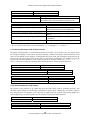
1
OPTO32 Optically Isolated I/O, 24 Input, 8 Output PMC-OPTO32A Software Development Kit SDK 5.0.0 Reference Manual Manual Revision: August 18, 2005 General Standards Corporation 8302A Whitesburg Drive Huntsville, AL 35802 Phone: (256) 880-8787 Fax: (256) 880-8788 URL: http://www.generalstandards.com E-mail: [email protected] E-mail: [email protected] OPTO32, Software Development Kit, Reference Manual 2 General Standards Corporation, Phone: (256) 880-8787 OPTO32, Software Development Kit, Reference Manual Preface Copyright ©2005, General Standards Corporation Additional copies of this manual or other literature may be obtained from: General Standards Corporation 8302A Whitesburg Dr. Huntsville, Alabama 35802 Phone: (256) 880-8787 FAX: (256) 880-8788 URL: http://www.generalstandards.com E-mail: [email protected] General Standards Corporation makes no warranty of any kind with regard to this material, including, but not limited to, the implied warranties of merchantability and fitness for a particular purpose. Although extensive editing and reviews are performed before release to ECO control, General Standards Corporation assumes no responsibility for any errors that may exist in this document. No commitment is made to update or keep current the information contained in this document. General Standards Corporation does not assume any liability arising out of the application or use of any product or circuit described herein, nor is any license conveyed under any patent rights or any rights of others. General Standards Corporation assumes no responsibility for any consequences resulting from omissions or errors in this manual or from the use of information contained herein. General Standards Corporation reserves the right to make any changes, without notice, to this product to improve reliability, performance, function, or design. ALL RIGHTS RESERVED. The Purchaser of this software may use or modify in source form the subject software, but not to re-market or distribute it to outside agencies or separate internal company divisions. The software, however, may be embedded in the Purchaser’s distributed software. In the event the Purchaser’s customers require the software source code, then they would have to purchase their own copy of the software. General Standards Corporation makes no warranty of any kind with regard to this software, including, but not limited to, the implied warranties of merchantability and fitness for a particular purpose and makes this software available solely on an “as-is” basis. General Standards Corporation reserves the right to make changes in this software without reservation and without notification to its users. The information in this document is subject to change without notice. This document may be copied or reproduced provided it is in support of products from General Standards Corporation. For any other use, no part of this document may be copied or reproduced in any form or by any means without prior written consent of General Standards Corporation. GSC is a trademark of General Standards Corporation. PLX and PLX Technology are trademarks of PLX Technology, Inc. 3 General Standards Corporation, Phone: (256) 880-8787 OPTO32, Software Development Kit, Reference Manual Table of Contents 1. Introduction............................................................................................................................... 7 1.1. Purpose ..............................................................................................................................................................7 1.2. Acronyms...........................................................................................................................................................7 1.3. Definitions..........................................................................................................................................................7 1.4. Installation.........................................................................................................................................................7 1.5. Application Programming Interface ...............................................................................................................7 1.6. Software Overview............................................................................................................................................8 1.6.1. Software Architecture...................................................................................................................................8 1.7. Hardware Overview..........................................................................................................................................8 1.8. Code Samples ....................................................................................................................................................9 1.9. Reference Material............................................................................................................................................9 2. Macros...................................................................................................................................... 10 2.1. API Version Number ......................................................................................................................................10 2.2. Common Parameter Assignment Values ......................................................................................................10 2.3. Discrete Data Type Options ...........................................................................................................................11 2.4. Maximum Number of Open Handles ............................................................................................................12 2.5. Parameter Access “Which” Bits ....................................................................................................................12 2.6. Registers...........................................................................................................................................................13 2.6.1. GSC Registers ............................................................................................................................................13 2.6.2. PLX PCI9080 PCI Configuration Registers ...............................................................................................13 2.6.3. PLX PCI9080 Feature Set Registers...........................................................................................................14 2.7. Version Data Selectors....................................................................................................................................16 3. Data Types ............................................................................................................................... 17 3.1. Discrete Data Types ........................................................................................................................................17 3.2. opto32_callback_func_t ..................................................................................................................................17 3.3. Status Values ...................................................................................................................................................17 4. Functions.................................................................................................................................. 19 4.1. opto32_api_status() .........................................................................................................................................19 4.2. opto32_board_count().....................................................................................................................................20 4.3. opto32_close() ..................................................................................................................................................21 4.4. opto32_config()................................................................................................................................................21 4.5. opto32_cos_read() ...........................................................................................................................................23 4.6. opto32_cos_write() ..........................................................................................................................................24 4.7. opto32_init() ....................................................................................................................................................24 4.8. opto32_irq_wait()............................................................................................................................................25 4 General Standards Corporation, Phone: (256) 880-8787 OPTO32, Software Development Kit, Reference Manual 4.9. opto32_open() ..................................................................................................................................................27 4.10. opto32_reg_mod() .........................................................................................................................................28 4.11. opto32_reg_read() .........................................................................................................................................29 4.12. opto32_reg_write()........................................................................................................................................29 4.13. opto32_reset() ................................................................................................................................................30 4.14. opto32_status_text()......................................................................................................................................31 4.15. opto32_version_get().....................................................................................................................................32 5. Configuration Parameters...................................................................................................... 34 5.1. Parameter Macros ..........................................................................................................................................34 5.1.1. Parameter Definitions .................................................................................................................................34 5.1.2. Value Definitions........................................................................................................................................34 5.1.3. Service Definitions .....................................................................................................................................34 5.1.3.1. Device Handle: h..................................................................................................................................34 5.1.3.2. Which Bits: w ......................................................................................................................................34 5.1.3.3. Set Value: s ..........................................................................................................................................34 5.1.3.4. Get Value: g .........................................................................................................................................35 5.2. Change Of State Parameters..........................................................................................................................35 5.2.1. COS Parameter: Debounce Divisor ............................................................................................................35 5.2.2. COS Parameter: Debounce Period In Milliseconds....................................................................................35 5.2.3. COS Parameter: Debounce Period In Microseconds ..................................................................................36 5.3. Interrupt Parameters......................................................................................................................................36 5.3.1. Interrupt Parameter: Callback Argument....................................................................................................37 5.3.2. Interrupt Parameter: Callback Function......................................................................................................37 5.3.3. Interrupt Parameter: COS 23 Event Counter ..............................................................................................38 5.3.4. Interrupt Parameter: COS Polarity..............................................................................................................38 5.3.5. Interrupt Parameter: Enable........................................................................................................................39 5.3.6. Interrupt Parameter: State...........................................................................................................................40 5.4. Miscellaneous Parameters..............................................................................................................................40 5.4.1. Miscellaneous Parameter: LED ..................................................................................................................40 5.4.2. Miscellaneous Parameter: GSC Register Mapping.....................................................................................41 5.4.3. Miscellaneous Parameter: GSC Register Mapping Pointer ........................................................................41 5.4.4. Miscellaneous Parameter: PLX Register Mapping.....................................................................................42 5.4.5. Miscellaneous Parameter: Strict Arguments...............................................................................................42 5.4.6. Miscellaneous Parameter: Strict Configuration..........................................................................................43 6. Operation ................................................................................................................................. 44 6.1. Overview ..........................................................................................................................................................44 6.2. Direct Register Access ....................................................................................................................................44 6.3. Data Input........................................................................................................................................................44 6.4. Data Output.....................................................................................................................................................45 6.5. Event Notification ...........................................................................................................................................45 6.5.1. Event Callback............................................................................................................................................45 6.5.1.1. Interrupt Notification Callback ............................................................................................................45 6.5.2. Event Waiting.............................................................................................................................................46 Document History ....................................................................................................................... 47 5 General Standards Corporation, Phone: (256) 880-8787 OPTO32, Software Development Kit, Reference Manual 6 General Standards Corporation, Phone: (256) 880-8787 OPTO32, Software Development Kit, Reference Manual 1. Introduction This reference manual applies to SDK release version 5.0.0. 1.1. Purpose The purpose of this document is to describe the Application Programming Interface to the OPTO32 Software Development Kit. This software provides the interface between “Application Software” and the OPTO32 board. The interface provided by the SDK is based on the board’s functionality. 1.2. Acronyms The following is a list of commonly occurring acronyms used throughout this document. Acronyms API GSC PCI PMC SDK Description Application Programming Interface General Standards Corporation Peripheral Component Interconnect PCI Mezzanine Card Software Development Kit (This is sometimes used synonymously with API or API Library.) 1.3. Definitions The following is a list of commonly occurring terms used throughout this document. Term API Library Application Driver Library Definition This refers to the library implementing the application level OPTO32 interface. (This is sometimes used synonymously with SDK or API.) This refers to user mode processes. This refers to the device driver, which runs under control of the operating system. This refers to the library module specific to the OS in use. 1.4. Installation Installation instructions for the SDK are provided in separate, operating system specific setup guides. 1.5. Application Programming Interface The SDK API is defined in the three header files listed below. These C language headers are C++ compatible. The only header that need be included by OPTO32 applications is opto32_api.h. The API consists of macros, data types, function calls and parameter definitions. These are described in other sections of this document. The headers define numerous items in addition to those described in this document. These additional items are provided without documentation. All software components of the API begin with a prefix of OPTO32 or GSC (both appear with upper and lower case letters). The table below indicates where to look for any particular item’s definition. File Name gsc_common.h gsc_pci9080.h opto32_api.h Description This header contains status definitions, a few data type definitions and a variety of macros. All items defined here have a prefix of “GSC” or “gsc”. This header contains register definitions for the PCI9080, which is the PCI interface chip used on OPTO32s. All items defined here have a prefix of “GSC” or “gsc” and include “9080”. This header contains the bulk of the API, including function calls, data types and numerous macros. All items defined here include the prefix “OPTO32” or “opto32”. 7 General Standards Corporation, Phone: (256) 880-8787 OPTO32, Software Development Kit, Reference Manual 1.6. Software Overview The software interface to the OPTO32 consists of a Device Driver and an API Library; the primary components of the SDK. The Device Driver operates under control of the operating system and must be loaded and running in order to access any installed OPTO32 devices. The interface provided by the API Library is based on the board’s functionality and is organized around the OPTO32’s set of main hardware features. The general categories are as follows and permit access to and manipulation of virtually every feature available on the board. • General Access Services (API Status, Version Numbers, Board Count, Open, Close, …) • Change of State Configuration • Other Miscellaneous Configuration • Interrupt Notification and Configuration All OPTO32 features are individually accessible via a generalized configuration service. For each parameter, as appropriate, the API includes a set of support macros. These include setting options (i.e. defaults and acceptable values), quick access retrieval macros, and quick access manipulation macros. All are described later in this document. 1.6.1. Software Architecture An application communicates with an OPTO32 using the driver and library described briefly above. Any number of applications may make simultaneous use of the library and each use is totally independent, unless specifically designed to do otherwise. Each instance provides access to at most 32 different OPTO32 devices. The diagram below describes the components and how they fit together. Application This is any application written to communicate with one or more OPTO32 devices using the driver and library provided in the SDK. API Library This library presents an OPTO32 feature based interface to applications wishing to communicate with OPTO32 devices. Device Driver OPTO32 The driver provides access to OPTO32 devices. This refers to any number of installed OPTO32 devices. NOTE: While multiple applications can gain access to the same device, this is discouraged since the driver maintains resources and settings per device rather than per application or device handle. 1.7. Hardware Overview The OPTO32 is a high performance optically isolated I/O board with Change Of State (COS) detection on all inputs. The board includes 24 optically isolated inputs and eight optically isolated outs. All inputs are controlled by a global debounce timer. The debounce period consists of three sampling intervals, where the interval is configurable in 100ns increments from 200ns to just under 215 seconds. The debounced input can be read at any time. Also, each COS input can be independently configured to generate an interrupt on either a rising or falling state transition. The D23 input has the added capability of generating an interrupt after receipt of from 1 to 64K low-to-high state changes. The eight outputs include four with normal output capability and four with high output capability. 8 General Standards Corporation, Phone: (256) 880-8787 OPTO32, Software Development Kit, Reference Manual 1.8. Code Samples All of the code samples in this manual are included in the opto32_dsl library along with their C source files. The examples given are notably simplistic, but are provided to illustrate use rather than accomplishment of broader tasks. 1.9. Reference Material The following reference material may be of particular benefit in using the OPTO32 and this SDK. The specifications provide the information necessary for an in-depth understanding of the specialized features implemented on this board. • The applicable OPTO32 User Manual from General Standards Corporation. • The PCI9080 PCI Bus Master Interface Chip data handbook from PLX Technology, Inc. * • The PLX PCI SDK, version 4.0.0 from PLX Technology, Inc. * * PLX material is available from PLX at the following location. PLX Technology Inc. 870 Maude Avenue Sunnyvale, California 94085 USA Phone: 1-800-759-3735 WEB: http://www.plxtech.com 9 General Standards Corporation, Phone: (256) 880-8787 OPTO32, Software Development Kit, Reference Manual 2. Macros The OPTO32 API includes the following macros. The headers also contain various other utility type macros, which are provided without documentation. Parameter support macros are not presented in this subsection. These macros are described in section 5 beginning on page 34. 2.1. API Version Number This macro defines the version number of the API’s executable interface. It does not refer to the SDK version number, the API Library version number or the Device Driver version number. Applications pass this value to the function opto32_api_status() (page 19), which is used to verify that the application and the library are compatible. Macros OPTO32_API_VERSION Description This is the API’s executable interface version number. 2.2. Common Parameter Assignment Values The below macros define universal values understood by all parameters to have special meanings, as given below. Any time a parameter assignment request is being carried out, use of these macros as the assignment value will produce the results given here. Macros GSC_DEFAULT GSC_NO_CHANGE Description Set the parameter to its default state/value. This is equivalent to using the explicitly defined default macro for the respective parameter. Do not change the parameter’s state/value. Since parameter access follows a set-then-get model, this value can be used to achieve a get only operation. Example #include <stdio.h> #include "opto32_api.h" #include "opto32_dsl.h" U32 opto32_dsl_led_reset(void* handle, int verbose) { U32 get; U32 status; // Reset the LED on/off state to its default. status = opto32_config( handle, OPTO32_MISC_LED, 0, GSC_DEFAULT, &get); if (!verbose) { } else if (status == GSC_SUCCESS) { printf("opto32_config() failure: %ld\n", (long) status); } else 10 General Standards Corporation, Phone: (256) 880-8787 OPTO32, Software Development Kit, Reference Manual { } } printf("LED State: "); if (get == OPTO32_MISC_LED_OFF) printf("Off\n"); else printf("On\n"); return(status); Example #include <stdio.h> #include "opto32_api.h" #include "opto32_dsl.h" U32 opto32_dsl_led_get(void* handle, int verbose, U32* get) { U32 status; // Reset the LED on/off state to its default. status = opto32_config( handle, OPTO32_MISC_LED, 0, GSC_NO_CHANGE, get); if (!verbose) { } else if (status == GSC_SUCCESS) { printf("opto32_config() failure: %ld\n", (long) status); } else { printf("LED State: "); } } if (get[0] == OPTO32_MISC_LED_OFF) printf("Off\n"); else printf("On\n"); return(status); 2.3. Discrete Data Type Options The below macros are defined by application code as needed to enable or disable declarations for and size validation for the data types S8, U8, S16, U16, S32 and U32 (see page 17). 11 General Standards Corporation, Phone: (256) 880-8787 OPTO32, Software Development Kit, Reference Manual Macros GSC_DATA_TYPES_CHECK GSC_DATA_TYPES_NOT_NEEDED Description If the API declares the data types and the application defines this macro, then the data type sizes will be validated during the application’s build process. This macro should only be defined if the compiler in use supports the sizeof() macro during preprocessing. Applications should define this macro before including opto32_api.h to disable the declarations for these data types. 2.4. Maximum Number of Open Handles This macro defines the maximum number of device handles that can be opened at any one time. All open handles are unique even if they refer to the same device, though handles are reused once closed. Macros GSC_PROCESS_OPEN_MAX Description This defines the maximum number of open handles. 2.5. Parameter Access “Which” Bits The table below lists the set of selection bits that may be set when a configuration parameter is modified or accessed. They are referred to as “which” bits in that they specify the objects which the parameter is to access. For example, to enable or disable the COS 0 interrupt the which value passed with the OPTO32_IRQ_ENABLE parameter must be OPTO32_WHICH_COS_00. When appropriate, bits within the same category may be bitwise or’d in order to apply the action to multiple objects. For retrieval purposes, the retrieved setting may reflect the setting of the first item accessed, the last item accessed, or all items collectively. The bits’ use is explained along with the parameters that each is associated with, and appears in subsequent portions of this document. Macros OPTO32_WHICH_COS_00 OPTO32_WHICH_COS_01 OPTO32_WHICH_COS_02 OPTO32_WHICH_COS_03 OPTO32_WHICH_COS_04 OPTO32_WHICH_COS_05 OPTO32_WHICH_COS_06 OPTO32_WHICH_COS_07 OPTO32_WHICH_COS_08 OPTO32_WHICH_COS_09 OPTO32_WHICH_COS_10 OPTO32_WHICH_COS_11 OPTO32_WHICH_COS_12 OPTO32_WHICH_COS_13 OPTO32_WHICH_COS_14 OPTO32_WHICH_COS_15 OPTO32_WHICH_COS_16 OPTO32_WHICH_COS_17 OPTO32_WHICH_COS_18 OPTO32_WHICH_COS_19 OPTO32_WHICH_COS_20 OPTO32_WHICH_COS_21 OPTO32_WHICH_COS_22 OPTO32_WHICH_COS_23 OPTO32_WHICH_COS_ALL OPTO32_WHICH_IRQ_ALL Description This identifies Change Of State input number 0. This identifies Change Of State input number 1. This identifies Change Of State input number 2. This identifies Change Of State input number 3. This identifies Change Of State input number 4. This identifies Change Of State input number 5. This identifies Change Of State input number 6. This identifies Change Of State input number 7. This identifies Change Of State input number 8. This identifies Change Of State input number 9. This identifies Change Of State input number 10. This identifies Change Of State input number 11. This identifies Change Of State input number 12. This identifies Change Of State input number 13. This identifies Change Of State input number 14. This identifies Change Of State input number 15. This identifies Change Of State input number 16. This identifies Change Of State input number 17. This identifies Change Of State input number 18. This identifies Change Of State input number 19. This identifies Change Of State input number 20. This identifies Change Of State input number 21. This identifies Change Of State input number 22. This identifies Change Of State input number 23. This identifies all of the Change Of State inputs. This identifies off interrupts sources. 12 General Standards Corporation, Phone: (256) 880-8787 OPTO32, Software Development Kit, Reference Manual OPTO32_WHICH_RECO This identifies the Receive Event Counter interrupt source. 2.6. Registers The following tables give the complete set of OPTO32 registers. The tables are divided by register categories. There are PCI registers, PLX feature set registers, and there are GSC firmware based registers. The PCI registers and the PLX registers are provided by the PCI interface chips used on the OPTO32. Applications have read access to all registers, but write access only to the GSC firmware registers. 2.6.1. GSC Registers The following table gives the complete set of GSC specific OPTO32 registers. For detailed definitions of these registers refer to the applicable OPTO32 User Manual. Macros OPTO32_BCR OPTO32_BSR OPTO32_CDR OPTO32_COSIER OPTO32_COSPR OPTO32_COSR OPTO32_ODR OPTO32_RDR OPTO32_RECR Description Board Control Register (BCR) Board Status Register (BSR) Clock Divider Register (CDR) Change Of State Interrupt Enable Register (COSIER) Change Of State Polarity Register (COSPR) Change Of State Register (COSR) Output Data Register (ODR) Receive Data Register (RDR) Receive Event Counter Register (RECR) 2.6.2. PLX PCI9080 PCI Configuration Registers The following table gives the set of PCI Configuration Registers. For detailed definitions of these registers refer to the PCI9080 Data Book. Macros GSC_PCI_9080_BAR0 GSC_PCI_9080_BAR1 GSC_PCI_9080_BAR2 GSC_PCI_9080_BAR3 GSC_PCI_9080_BAR4 GSC_PCI_9080_BAR5 GSC_PCI_9080_BISTR GSC_PCI_9080_CCR GSC_PCI_9080_CIS GSC_PCI_9080_CLSR GSC_PCI_9080_CR GSC_PCI_9080_DIDR GSC_PCI_9080_ERBAR GSC_PCI_9080_HTR GSC_PCI_9080_ILR GSC_PCI_9080_IPR GSC_PCI_9080_LTR GSC_PCI_9080_MGR GSC_PCI_9080_MLR Description PCI Base Address Register for Memory Accesses to Local, Runtime, and DMA Registers (PCIBAR0) PCI Base Address Register for I/O Accesses to Local, Runtime, and DMA Registers (PCIBAR1) PCI Base Address Register for Memory Accesses to Local Address Space 0 (PCIBAR2) PCI Base Address Register for Memory Accesses to Local Address Space 1 (PCIBAR3) Unused Base Address Register (PCIBAR4) Unused Base Address Register (PCIBAR5) PCI Built-In Self Test Register (PCIBISTR) PCI Class Code Register (PCICCR) PCI Cardbus CIS Pointer Register (PCICIS) PCI Cache Line Size Register (PCICLSR) PCI Command Register (PCICR) PCI Device ID Register (PCIDIDR) PCI Expansion ROM Base Address (PCIERBAR) PCI Header Type Register (PCIHTR) PCI Interrupt Line Register (PCIILR) PCI Interrupt Pin Register (PCIIPR) PCI Latency Timer Register (PCILTR) PCI Min_Gnt Register (PCIMGR) PCI Max_Lat Register (PCIMLR) 13 General Standards Corporation, Phone: (256) 880-8787 OPTO32, Software Development Kit, Reference Manual GSC_PCI_9080_REV GSC_PCI_9080_SID GSC_PCI_9080_SR GSC_PCI_9080_SVID GSC_PCI_9080_VIDR PCI Revision ID Register (PCIREV) PCI Subsystem ID Register (PCISID) PCI Status Register (PCISR) PCI Subsystem Vendor ID Register (PCISVID) PCI Vendor ID Register (PCIVIDR) NOTE: The following table gives those registers and values that uniquely identify OPTO32 boards. Register GSC_PCI_9080_VIDR GSC_PCI_9080_DIDR Value 0x10B5 0x906E GSC_PCI_9080_SVID GSC_PCI_9080_SID 0x10B5 0x9080 Description The PCI interface chip as a PLX device. The PCI interface chip is reported as a PLX PCI9060E, though it is actually a PLX PCI9080. The PCI interface chip as a PLX device. The PCI interface chip is a PLX PCI9080. 2.6.3. PLX PCI9080 Feature Set Registers The following tables give the set of PLX feature set registers. Local Configuration Registers The following table gives the set of PLX Local Configuration Registers. For detailed definitions of these registers refer to the PCI9080 Data Book. Macros GSC_PLX_9080_BIGEND GSC_PLX_9080_DMCFGA GSC_PLX_9080_DMLBAM GSC_PLX_9080_DMLBAI GSC_PLX_9080_DMPBAM GSC_PLX_9080_DMRR GSC_PLX_9080_EROMBA GSC_PLX_9080_EROMRR GSC_PLX_9080_LAS0BA GSC_PLX_9080_LAS0RR GSC_PLX_9080_LAS1BA GSC_PLX_9080_LAS1RR GSC_PLX_9080_LBRD0 GSC_PLX_9080_LBRD1 GSC_PLX_9080_MARBR Description Big/Little Endian Descriptor Register (BIGEND) PCI Configuration Address Register for Direct Master to PCI IO/CFG (DMCFGA) Local Bus Base Address Register for Direct Master to PCI Memory (DMLBAM) Local Bus Base Address Register for Direct Master to PCI IO/CFG (DMLBAI) PCI Base Address Register for Direct Master to PCI Memory (DMPBAM) Local Range Register for Direct Master to PCI (DMRR) Expansion ROM Local Base Address Register (EROMBA) Expansion ROM Range Register (EROMRR) Local Address Space 0 Local Base Address Register (LASOBA) Local Address Space 0 Range Register for PCI-to-Local Bus (LASORR) Local Address Space 1 Local Base Address Register (LAS1BA) Local Address Space 1 Range Register for PCI-to-Local Bus (LAS1RR) Local Address Space 0/Expansion ROM Bus Region Descriptor Register (LBRD0) Local Address Space 1 Bus Region Descriptor Register (LBRD1) Mode Arbitration Register (MARBR) Runtime Registers The following table gives the set of PLX Runtime Registers. For detailed definitions of these registers refer to the PCI9080 Data Book. Macros GSC_PLX_9080_CNTRL GSC_PLX_9080_INTCSR GSC_PLX_9080_L2PDBELL GSC_PLX_9080_MBOX0 GSC_PLX_9080_MBOX1 Description Serial EEPROM Control, CPI Command Codes, User I/O, Init Control Register (CNTRL) Interrupt Control/Status Register (INTCSR) Local-to-PCI Doorbell Register (L2PDBELL) Mailbox Register 0 (MBOX0) Mailbox Register 1 (MBOX1) 14 General Standards Corporation, Phone: (256) 880-8787 OPTO32, Software Development Kit, Reference Manual GSC_PLX_9080_MBOX2 GSC_PLX_9080_MBOX3 GSC_PLX_9080_MBOX4 GSC_PLX_9080_MBOX5 GSC_PLX_9080_MBOX6 GSC_PLX_9080_MBOX7 GSC_PLX_9080_P2LDBELL GSC_PLX_9080_PCIHIDR GSC_PLX_9080_PCIHREV Mailbox Register 2 (MBOX2) Mailbox Register 3 (MBOX3) Mailbox Register 4 (MBOX4) Mailbox Register 5 (MBOX5) Mailbox Register 6 (MBOX6) Mailbox Register 7 (MBOX7) PCI-to-Local Doorbell Register (P2LDBELL) PCI Permanent Configuration ID Register (PCIHIDR) PCI Permanent Revision ID Register (PCIHREV) DMA Registers The following table gives the set of PLX DMA Registers. For detailed definitions of these registers refer to the PCI9080 Data Book. These register definitions are provided for informational purposes only as the OPTO32 implements no features that might use DMA. Macros GSC_PLX_9080_DMAARB GSC_PLX_9080_DMACSR0 GSC_PLX_9080_DMACSR1 GSC_PLX_9080_DMADPR0 GSC_PLX_9080_DMADPR1 GSC_PLX_9080_DMALADR0 GSC_PLX_9080_DMALADR1 GSC_PLX_9080_DMAMODE0 GSC_PLX_9080_DMAMODE1 GSC_PLX_9080_DMAPADR0 GSC_PLX_9080_DMAPADR1 GSC_PLX_9080_DMASIZ0 GSC_PLX_9080_DMASIZ1 GSC_PLX_9080_DMATHR Description DMA Arbitration Register (DMAARB) DMA Channel 0 Command/Status Register (DMACSR0) DMA Channel 1 Command/Status Register (DMACSR1) DMA Channel 0 Descriptor Pointer Register (DMADPR0) DMA Channel 1 Descriptor Pointer Register (DMADPR1) DMA Channel 0 Local Address Register (DMALADR0) DMA Channel 1 Local Address Register (DMALADR1) DMA Channel 0 Mode Register (DMAMODE0) DMA Channel 1 Mode Register (DMAMODE1) DMA Channel 0 PCI Address Register (DMAPADR0) DMA Channel 1 PCI Address Register (DMAPADR1) DMA Channel 0 Transfer Size Register (DMASIZ0) DMA Channel 1 Transfer Size Register (DMASIZ1) DMA Threshold Register (DMATHR) Message Queue Registers The following table gives the set of PLX Messaging Queue Registers. For detailed definitions of these registers refer to the PCI9080 Data Book. Macros GSC_PLX_9080_IFHPR GSC_PLX_9080_IFTPR GSC_PLX_9080_IPHPR GSC_PLX_9080_IPTPR GSC_PLX_9080_IQP GSC_PLX_9080_MQCR GSC_PLX_9080_OFHPR GSC_PLX_9080_OFTPR GSC_PLX_9080_OPHPR GSC_PLX_9080_OPLFIM GSC_PLX_9080_OPLFIS GSC_PLX_9080_OPTPR GSC_PLX_9080_OQP GSC_PLX_9080_QBAR GSC_PLX_9080_QSR Description Inbound Free Head Pointer Register (IFHPR) Inbound Free Tail Pointer Register (IFTPR) Inbound Post Head Pointer Register (IPHPR) Inbound Post Tail Pointer Register (IPTPR) Inbound Queue Port Register (IQP) Messaging Queue Configuration Register (MQCR) Outbound Free Head Pointer Register (OFHPR) Outbound Free Tail Pointer Register (OFTPR) Outbound Post Head Pointer Register (OPHPR) Outbound Post List FIFO Interrupt Mask Register (OPLFIM) Outbound Post List FIFO Interrupt Status Register (OPLFIS) Outbound Post Tail Pointer Register (OPTPR) Outbound Queue Port Register (OQP) Queue Base Address Register (QBAR) Queue Status/Control Register (QSR) 15 General Standards Corporation, Phone: (256) 880-8787 OPTO32, Software Development Kit, Reference Manual 2.7. Version Data Selectors This set of macros is used when requesting a version number and indicates which version number is desired. The macros are passed as the id argument to the opto32_version_get() function (see page 32). The second table below lists utility macros used to retrieve each of the respective version numbers. In the second table, the argument h refers to the handle used to access the device, the b refers to an application buffer where the version string is recorded, and the s is the size of that buffer. Macros (Values) GSC_VERSION_LIBRARY GSC_VERSION_DRIVER Description This requests the library’s version number. This requests the driver’s version number. Macro (Services) OPTO32_VERSION_GET_LIBRARY(h,b,s) OPTO32_VERSION_GET_DRIVER(h,b,s) Description This requests the version number for the API Library. This requests the version number for the Device Driver. 16 General Standards Corporation, Phone: (256) 880-8787 OPTO32, Software Development Kit, Reference Manual 3. Data Types The interface includes the following data types. 3.1. Discrete Data Types The following discrete data types are defined and used by the API. If an OPTO32 application includes other headers which also define these types, then the API can be directed to omit these definitions. This is done by defining the macro GSC_DATA_TYPES_NOT_NEEDED before including the API header. The alternate definitions must however define these types as listed in the below table. Data Type S8 U8 S16 U16 S32 U32 Description This is an 8-bit signed integer. This is an 8-bit unsigned integer. This is a 16-bit signed integer. This is a 16-bit unsigned integer. This is a 32-bit signed integer. This is a 32-bit unsigned integer. 3.2. opto32_callback_func_t This is the data type required for all event notification callback functions. This applies to Interrupt Notification callbacks. Definition typedef void (*opto32_callback_func_t)(U32 arg1, U32 arg2, U32 arg3); Arguments arg1 arg2 arg3 Description This is the device handle cast to a U32 data type. For Interrupt Notification this is the OPTO32_WHICH_XXX bit for the respective interrupt. This is any arbitrary application supplied data value. 3.3. Status Values This unnamed enumerated data type lists all possible status values returnable from API service calls. The enumerated values represent common definitions used by this and other GSC SDKs. Many values will never be encountered when using the OPTO32 SDK. The table below gives brief descriptions for many values and omits those that should never be seen. The most common value encountered is GSC_SUCCESS and indicates that the request was completed successfully. Definition typedef enum { … }; Values GSC_ABORTED GSC_ACCESS_DENIED Description An I/O operation was aborted due to a user’s explicit or implicit request. The operation failed because access to a device, service 17 General Standards Corporation, Phone: (256) 880-8787 OPTO32, Software Development Kit, Reference Manual GSC_FAILED GSC_INIT_FAILURE GSC_INSUFFICIENT_RESOURCES GSC_INVALID_API_HANDLE GSC_INVALID_DATA GSC_INVALID_VERSION_API GSC_INVALID_VERSION_DIL GSC_INVALID_VERSION_DRIVER GSC_LIB_FUNCTION_ACCESS_FAILURE GSC_NULL_PARAM GSC_SUCCESS GSC_THREAD_FAILURE GSC_TOO_MANY_OPEN_HANDLES GSC_WAIT_TIMEOUT GSC_WAIT_CANCELED or system resource or service was denied. An operation failed in a non-specific manner. API Library initialization failed. An operation failed because insufficient OS resources were available. An operation failed because the application supplied an invalid device handle. API device handles are API specific resources and are of no meaning to the OS. An operation failed because invalid data was provided. API Library initialization failed because the API Library version was incompatible. This refers either to the API’s version number or the GSC revision level. The version data can still be retrieved when this status is seen. API Library initialization failed because the Driver Interface Library version was incompatible. This refers either to the library’s version number or the GSC revision level. The version data can still be retrieved when this status is seen. API Library initialization failed because the Device Driver version was incompatible. This refers either to the driver’s version number or the GSC revision level. The version data can still be retrieved when this status is seen. API Library initialization failed because the API could not access a Driver Interface Library function. An operation failed because an argument was NULL. An operation completed successfully. An operation (opto32_open()) failed because a support thread could not be started. An operation (opto32_open()) failed because the application attempted too many simultaneous device accesses. An operation completed because a timeout period lapsed. An operation waiting for an event ended prematurely. This usually means the application was terminated while waiting for the event. 18 General Standards Corporation, Phone: (256) 880-8787 OPTO32, Software Development Kit, Reference Manual 4. Functions The OPTO32 API includes the following functions. The SDK interface also includes a number of function style macro definitions. These macros are described in section 5 beginning on page 34. 4.1. opto32_api_status() This function is the entry point to determine the status of the API Library. This must be the very first call into the API and determines the usability of the API Library and the Device Driver. If the initial status obtained is other than GSC_SUCCESS, then only a limited portion of the API is functional. If not fully usable, then both values returned may be useful in resolving the situation. Thereafter, the status obtained might vary if the API encounters irregular circumstances. The table below lists the utility macros available for this service. Macro (Services) OPTO32_API_STATUS(s,a) Description Retrieve the status information without having to explicitly enter the macro for the current API version. Prototype U32 opto32_api_status(U32* stat, U32* arg, U32 api_ver); Argument stat arg api_ver Description The API records the current API status here, which can change during use. The pointer must not be NULL. The API records auxiliary status information here, which can change during use. This value should be related to the above reported status. The pointer must not be NULL. This must be the version number of the API the application was written for. If this number does not match, then the API is unusable by the application. Return Value GSC_SUCCESS Otherwise … Description The operation succeeded (the status was retrieved). A GSC_XXX error status reflecting the problem encountered. Example #include <stdio.h> #include "opto32_api.h" #include "opto32_dsl.h" U32 opto32_dsl_api_status(int verbose) { U32 arg; U32 stat; U32 status; status = opto32_api_status(&stat, &arg, OPTO32_API_VERSION); if (!verbose) { } else if (status != GSC_SUCCESS) { printf("opto32_api_status() failure: 0x%lX\n", (long) status); } 19 General Standards Corporation, Phone: (256) 880-8787 OPTO32, Software Development Kit, Reference Manual else { status = stat; printf("API Status:\n"); printf(" Status: 0x%lX\n", (long) stat); printf(" Argument: 0x%lX\n", (long) arg); } } return(status); 4.2. opto32_board_count() This function is the entry point to determine the number of OPTO32 boards installed in the system and accessible to the API. This service can be called without requiring access to any particular device. Prototype U32 opto32_board_count(U8* count); Argument count Description The API records the number of boards at this location. This pointer must not be NULL. Return Value GSC_SUCCESS Otherwise … Description The operation succeeded. A GSC_XXX error status reflecting the problem encountered. Example #include <stdio.h> #include "opto32_api.h" #include "opto32_dsl.h" U32 opto32_dsl_board_count(U8* count, int verbose) { U32 status; status = opto32_board_count(count); if (!verbose) { } else if (status != GSC_SUCCESS) { printf("opto32_board_count() failure: 0x%lX\n", (long) status); } else { printf("OPTO32 Board Count: %d\n", (int) count[0]); } } return(status); 20 General Standards Corporation, Phone: (256) 880-8787 OPTO32, Software Development Kit, Reference Manual 4.3. opto32_close() This function is the entry point to close a connection to an open OPTO32 board. The function should only be called after a successful open of the respective device via opto32_open() and must not be used after being closed. Before returning, the API returns the device to the same state produced when originally opened. Prototype U32 opto32_close(void* handle); Argument handle Description This is an API device handle obtained via opto32_open(). Return Value GSC_SUCCESS Otherwise … Description The operation succeeded. A GSC_XXX error status reflecting the problem encountered. Example #include <stdio.h> #include "opto32_api.h" #include "opto32_dsl.h" U32 opto32_dsl_close(void* handle, int verbose) { U32 status; status = opto32_close(handle); if (!verbose) { } else if (status != GSC_SUCCESS) { printf("opto32_close() failure: 0x%lX\n", (long) status); } else { printf("Device Closed: 0x%lX\n", (long) handle); } } return(status); 4.4. opto32_config() This function is the entry point to accessing an individual parameter where all pertinent data is given as separate arguments. The function should only be called after a successful open of the respective device via opto32_open(). Prototype U32 opto32_config( void* handle, 21 General Standards Corporation, Phone: (256) 880-8787 OPTO32, Software Development Kit, Reference Manual U32 U32 U32 U32* Argument handle parm which set get parm, which, set, get); Description This is an API device handle obtained via opto32_open(). This is the Parameter Identifier for the parameter to be accessed. This is any number or combination of parameter specific OPTO32_WHICH_XXX bits that specify the object(s) the parameter is applied to. Many parameters ignore this argument. When it is used, a value of zero is acceptable, and merely specifies to access none of the corresponding objects. This is the value to apply to the parameter being accessed. The universal value GSC_NO_CHANGE specifies that the parameter not be altered and must be used when the purpose of the access is to get the current setting. Some parameters are read-only, in which case this argument is ignored. After applying any changes to the parameter, its current setting is recorded here. When the “which” argument specifies multiple objects, the value recorded here may be from the first object accessed, the last or a collective result. This argument may be NULL, in which case the current setting is not retrieved. Return Value GSC_SUCCESS Otherwise … Description The operation succeeded. A GSC_XXX error status reflecting the problem encountered. Example #include <stdio.h> #include "opto32_api.h" #include "opto32_dsl.h" U32 opto32_dsl_led_set(void* handle, U32 set, int verbose) { U32 get; U32 status; // Reset the LED on/off state to its default. status = opto32_config( handle, OPTO32_MISC_LED, 0, set, &get); if (!verbose) { } else if (status == GSC_SUCCESS) { printf("opto32_config() failure: %ld\n", (long) status); } else { printf("LED State: "); 22 General Standards Corporation, Phone: (256) 880-8787 OPTO32, Software Development Kit, Reference Manual } } if (get == OPTO32_MISC_LED_OFF) printf("Off\n"); else printf("On\n"); return(status); 4.5. opto32_cos_read() This function is the entry point to reading the current debounced input from the cable. The function should only be called after a successful open of the respective device via opto32_open(). Prototype U32 opto32_cos_read(void* handle, U32* value); Argument handle value Description This is an API device handle obtained via opto32_open(). The value read is recorded here. The upper eight bits will always be zero. Return Value GSC_SUCCESS Otherwise … Description The operation succeeded. A GSC_XXX error status reflecting the problem encountered. Example #include <stdio.h> #include "opto32_api.h" #include "opto32_dsl.h" U32 opto32_dsl_cos_read(void* handle, U32* value, int verbose) { U32 status; status = opto32_cos_read(handle, value); if (!verbose) { } else if (status != GSC_SUCCESS) { printf("opto32_cos_read() failure: %ld\n", (long) status); } else { printf("COS Read: 0x%06lX\n", (long) value[0]); } } return(status); 23 General Standards Corporation, Phone: (256) 880-8787 OPTO32, Software Development Kit, Reference Manual 4.6. opto32_cos_write() This function is the entry point to writing to the cable’s output signals. The function should only be called after a successful open of the respective device via opto32_open(). Prototype U32 opto32_cos_write(void* handle, U8 value); Argument handle value Description This is an API device handle obtained via opto32_open(). This is the value to write. Return Value GSC_SUCCESS Otherwise … Description The operation succeeded. A GSC_XXX error status reflecting the problem encountered. Example #include <stdio.h> #include "opto32_api.h" #include "opto32_dsl.h" U32 opto32_dsl_cos_write(void* handle, U8 value, int verbose) { U32 status; status = opto32_cos_write(handle, value); if (!verbose) { } else if (status != GSC_SUCCESS) { printf("opto32_cos_write() failure: %ld\n", (long) status); } else { printf("COS Write: 0x%02lX\n", (long) value); } } return(status); 4.7. opto32_init() This function is the entry point to return a device and all parameters to the state produced when the device was first opened. This function should only be called after a successful open of the respective device via opto32_open(). Prototype U32 opto32_init(void* handle); 24 General Standards Corporation, Phone: (256) 880-8787 OPTO32, Software Development Kit, Reference Manual Argument handle Description This is an API device handle obtained via opto32_open(). Return Value GSC_SUCCESS Otherwise … Description The operation succeeded. A GSC_XXX error status reflecting the problem encountered. Example #include <stdio.h> #include "opto32_api.h" #include "opto32_dsl.h" U32 opto32_dsl_init(void* handle, int verbose) { U32 status; status = opto32_init(handle); if (!verbose) { } else if (status != GSC_SUCCESS) { printf("opto32_init() failure: 0x%lX\n", (long) status); } else { printf("Device Initialized: 0x%lX\n", (long) handle); } } return(status); 4.8. opto32_irq_wait() This function is the entry point to pause thread execution until an interrupt occurs. The function should only be called after a successful open of the respective device via opto32_open(). When called, the current thread will block until any one of a specified set of interrupts occurs. The call will return as soon as the time period expires, or when the first referenced interrupt occurs, whichever occurs first. There is no limit to the number of threads that may simultaneously utilize this service or on the combination of interrupts that may be referenced. Applications can use the utility macros OPTO32_IRQ_WAIT__XXX(h) to perform waits on individual interrupts without having to explicitly enter the macro for the respective interrupt. In these macros, the XXX may be COS_00 through COS_23 for COS inputs zero through 23, respectively, or RECO for the COS 23 Rx Event Counter Overflow. See the table below. Macro (Services) OPTO32_IRQ_WAIT__COS_XX(h,to) OPTO32_IRQ_WAIT__RECO(h,to) Description Wait for COS interrupt XX. * Wait for the Receive Event Count interrupt. * The XX portion of these macros refers individually to COS interrupts 00 through 23. 25 General Standards Corporation, Phone: (256) 880-8787 OPTO32, Software Development Kit, Reference Manual Prototype U32 opto32_irq_wait(void* handle, U32 which, U32 timeout_ms); Argument handle which timeout_ms Description This is an API device handle obtained via opto32_open(). This is any bitwise or’d combination of OPTO32_WHICH_XXX bits applicable to interrupts. Set the bits according to the interrupts of interest. Unreferenced interrupts will have no impact. If none are set the function returns immediately with GSC_SUCCESS. This is the timeout limit is milliseconds. If an interrupt does not occur within this time period, then the call returns at the end of the period. The timeout period will be at least the amount of time specified, but may be longer depending on the OS. Return Value GSC_SUCCESS GSC_WAIT_TIMEOUT Otherwise … Description Either no interrupts were referenced or one of the referenced interrupts occurred. No indication is given to indicate which interrupt, if any, caused the call to return. The timeout period expired before a referenced interrupt occurred. A GSC_XXX error status reflecting the problem encountered. Example #include <stdio.h> #include "opto32_api.h" #include "opto32_dsl.h" U32 opto32_dsl_event_count_wait( void* handle, long timeout_ms, int verbose) { U32 status; status = opto32_irq_wait(handle, OPTO32_WHICH_RECO, timeout_ms); if (!verbose) { } else if (status == GSC_SUCCESS) { printf("IRQ COS 23 Event Count: interrupt occurred.\n"); } else if (status == GSC_WAIT_TIMEOUT) { printf( "IRQ COS 23 Event Count:" " timeout after %ld milliseconds\n", (long) timeout_ms); } else { printf("opto32_irq_wait() failure: %ld\n", (long) status); } 26 General Standards Corporation, Phone: (256) 880-8787 OPTO32, Software Development Kit, Reference Manual } return(status); 4.9. opto32_open() This function is the entry point to open a connection to an OPTO32 board. This function must be called before any other device access functions may be called. If successful, the device and all parameters are initialized to default settings. Multiple requests can be made to access the same device, and each can succeed. However, care must be taken when doing this as device access via one handle is likely to interfere with the device state maintained by the other. Additionally, one handle may configure the device in a way that conflicts with the configuration established by the other. Prototype U32 opto32_open(U8 index, void** handle); Argument index handle Description This is the zero based index of the board to access. If the request succeeds, the API records at this address the handle to be used for subsequent access to the respective device. This pointer must not be NULL. The pointer returned will be NULL if the request fails and non-NULL otherwise. Return Value GSC_SUCCESS Otherwise … Description The operation succeeded. A GSC_XXX error status reflecting the problem encountered. Example #include <stdio.h> #include "opto32_api.h" #include "opto32_dsl.h" U32 opto32_dsl_open(U8 index, void** handle, int verbose) { U32 status; status = opto32_open(index, handle); if (!verbose) { } else if (status != GSC_SUCCESS) { printf("opto32_open() failure: %ld\n", (long) status); } else { printf("Device Opened:\n"); printf(" Index: 0x%lX\n", (long) index); printf(" Handle: 0x%lX\n", (long) handle); } } return(status); 27 General Standards Corporation, Phone: (256) 880-8787 OPTO32, Software Development Kit, Reference Manual 4.10. opto32_reg_mod() This function is the entry point to performing a read-modify-write operation on an OPTO32 register. The function should only be called after a successful open of the respective device via opto32_open(). Only GSC firmware register may be modified. The PCI and PLX feature set registers are read-only. Prototype U32 opto32_reg_mod(void* handle, U32 reg, U32 value, U32 mask); Argument handle reg value mask Description This is an API device handle obtained via opto32_open(). This is the register to access. This is the value for the bits to be modified. This is the set of register bit to be modified. All others are unchanged. Return Value GSC_SUCCESS Otherwise … Description The operation succeeded. A GSC_XXX error status reflecting the problem encountered. Example #include <stdio.h> #include "opto32_api.h" #include "opto32_dsl.h" U32 opto32_dsl_cosier_mod( void* handle, U32 value, U32 mask, int verbose) { U32 status; status = opto32_reg_mod(handle, OPTO32_COSIER, value, mask); if (!verbose) { } else if (status != GSC_SUCCESS) { printf("opto32_reg_mod() failure: 0x%lX\n", (long) status); } else { printf("COSIER Modify:\n"); printf(" Value: 0x%lX\n", (long) value); printf(" Mask: 0x%lX\n", (long) mask); } } return(status); 28 General Standards Corporation, Phone: (256) 880-8787 OPTO32, Software Development Kit, Reference Manual 4.11. opto32_reg_read() This function is the entry point to reading the value from an OPTO32 register. The function should only be called after a successful open of the respective device via opto32_open(). All OPTO32 registers may be read. Prototype U32 opto32_reg_read(void* handle, U32 reg, U32* value); Argument handle reg value Description This is an API device handle obtained via opto32_open(). This is the register to access. The value read is recorded here. If this is NULL then no action is taken. Return Value GSC_SUCCESS Otherwise … Description The operation succeeded. A GSC_XXX error status reflecting the problem encountered. Example #include <stdio.h> #include "opto32_api.h" #include "opto32_dsl.h" U32 opto32_dsl_cosier_read(void* handle, U32* value, int verbose) { U32 status; status = opto32_reg_read(handle, OPTO32_COSIER, value); if (!verbose) { } else if (status != GSC_SUCCESS) { printf("opto32_reg_read() failure: 0x%lX\n", (long) status); } else { printf("COSIER Read: 0x%lX\n", (long) value[0]); } } return(status); 4.12. opto32_reg_write() This function is the entry point to writing to an OPTO32 register. The function should only be called after a successful open of the respective device via opto32_open(). Only the OPTO32 firmware registers (those defined inside opto32_api.h) may be modified. All PCI and PLX registers are read-only. Prototype U32 opto32_reg_write(void* handle, U32 reg, U32 value); 29 General Standards Corporation, Phone: (256) 880-8787 OPTO32, Software Development Kit, Reference Manual Argument handle reg value Description This is an API device handle obtained via opto32_open(). This is the register to access. This is the value to write to the specified register. Return Value GSC_SUCCESS Otherwise … Description The operation succeeded. A GSC_XXX error status reflecting the problem encountered. Example #include <stdio.h> #include "opto32_api.h" #include "opto32_dsl.h" U32 opto32_dsl_cosier_write(void* handle, U32 value, int verbose) { U32 status; status = opto32_reg_write(handle, OPTO32_COSIER, value); if (!verbose) { } else if (status != GSC_SUCCESS) { printf("opto32_reg_write() failure: 0x%lX\n", (long) status); } else { printf("COSIER Write: 0x%lX\n", (long) value); } } return(status); 4.13. opto32_reset() This function is the entry point to perform a device hardware reset. The function should only be called after a successful open of the respective device via opto32_open(). WARNING: The API performs a variety of actions during this call that are in addition to resetting the hardware. This is necessary for proper API operation. If an application initiates a hardware reset by writing to the various registers the results may not be identical. Prototype U32 opto32_reset(void* handle); Argument handle Description This is an API device handle obtained via opto32_open(). Return Value GSC_SUCCESS Description The operation succeeded. 30 General Standards Corporation, Phone: (256) 880-8787 OPTO32, Software Development Kit, Reference Manual Otherwise … A GSC_XXX error status reflecting the problem encountered. Example #include <stdio.h> #include "opto32_api.h" #include "opto32_dsl.h" U32 opto32_dsl_reset(void* handle, int verbose) { U32 status; status = opto32_reset(handle); if (!verbose) { } else if (status != GSC_SUCCESS) { printf("opto32_reset() failure: 0x%lX\n", (long) status); } else { printf("Device Reset: 0x%lX\n", (long) handle); } } return(status); 4.14. opto32_status_text() This function is the entry point to retrieving a text based description of the status values supported by the SDK. Prototype U32 opto32_status_text(U32 status, char* text, size_t size); Argument status text size Description This is the status value whose description is desired. The descriptive text is recorded here. This gives the size of the above buffer. Return Value GSC_SUCCESS Otherwise … Description The operation succeeded. A GSC_XXX error status reflecting the problem encountered. Example #include <stdio.h> #include "opto32_api.h" #include "opto32_dsl.h" U32 opto32_dsl_status_text(U32 stat, int verbose) 31 General Standards Corporation, Phone: (256) 880-8787 OPTO32, Software Development Kit, Reference Manual { char U32 buf[128]; status; status = opto32_status_text(stat, buf, sizeof(buf)); if (!verbose) { } else if (status != GSC_SUCCESS) { printf("opto32_status_text() failure: 0x%lX\n", (long) status); } else { printf("Status: 0x%lX: %s\n", (long) stat, buf); } } return(status); 4.15. opto32_version_get() This function is the entry point to retrieving version number strings. Without a valid device handle, only the API Library version number is accessible. Access to the Device Driver’s version number requires a valid device handle. Prototype U32 opto32_version_get( void* handle, U8 index, char* version, size_t size); Argument handle index version size Description This is an API device handle obtained via opto32_open(). This identifies the version number desired. It must be one of the GSC_VERSION_XXX macros. The requested version string is recorded here. This is the size of the above buffer. Return Value GSC_SUCCESS Otherwise … Description The operation succeeded. A GSC_XXX error status reflecting the problem encountered. Example #include <stdio.h> #include "opto32_api.h" #include "opto32_dsl.h" U32 opto32_dsl_version_get(void* handle, U8 id, int verbose) { U32 status; 32 General Standards Corporation, Phone: (256) 880-8787 OPTO32, Software Development Kit, Reference Manual char status version[32]; = opto32_version_get( handle, id, version, sizeof(version)); if (!verbose) { } else if (status != GSC_SUCCESS) { printf("opto32_version_get() failure: 0x%lX\n", (long) status); } else if (id == GSC_VERSION_LIBRARY) { printf("Library Version: %s\n", version); } else { printf("Driver Version: %s\n", version); } } return(status); 33 General Standards Corporation, Phone: (256) 880-8787 OPTO32, Software Development Kit, Reference Manual 5. Configuration Parameters 5.1. Parameter Macros The Configuration Parameters are grouped according to their functional categories. Within each category each parameter is described (in this section) along with the set of utility macros designed to facilitate configuration of and access to the respective parameters. Parameter macros fall into three groups, which are described the following paragraphs. All macros are described in the following pages in association with their respective parameters. The parameter categories are as given in the below table. Parameter Categories OPTO32_COS_XXX OPTO32_IRQ_XXX OPTO32_MISC_XXX Description These refer to the Change Of State Parameters. These refer to the Interrupt Parameters. These refer to the Miscellaneous Parameters. 5.1.1. Parameter Definitions The first group of macros includes the parameter definitions. These are used to identify the specific parameter to be accessed. These macros begin with “OPTO32_” and are followed immediately by upper case letters identifying the parameter category. For example “OPTO32_MISC_” prefaces all Miscellaneous Parameter identifiers. These macros end with upper case letters indicating the name of the specific parameter. For example “OPTO32_MISC_STRICT_ARGUMENTS” identifies the Miscellaneous Strict Arguments parameter. 5.1.2. Value Definitions The second group of macros identifies predefined values associated with the respective parameters. These macros begin with the Parameter Definition and are followed by a single underscore (“_”) then upper case letters that reflect the meaning of the respective values. For example the macro “OPTO32_MISC_STRICT_ARGUMENTS_DISABLE” is the value that represents the parameter’s disabled setting. 5.1.3. Service Definitions The third group of macros performs operations on parameters. These are utility macros that retrieve parameter settings and states or assign parameter values. These macros include the Parameter Definition followed by a double underscore (“__”) then upper case letters that reflect the action to perform. For example “OPTO32_MISC_STRICT_ARGUMENTS__GET()” retrieves the current setting of the Miscellaneous Strict Arguments parameter. These macros include arguments, which are described as follows. 5.1.3.1. Device Handle: h In the service macros, the argument h refers to the device handle used to access the respective device. This handle is obtained by calling opto32_open(). This argument must not be NULL. 5.1.3.2. Which Bits: w In the service macros, the argument w refers to any combination of the OPTO32_WHICH_XXX bits. Refer to paragraph 2.5 on page 12. With some parameters this argument is unused or is specified inside the macro’s replacement text. In those cases the w is not included as a macro argument. 5.1.3.3. Set Value: s In the service macros, the argument s refers to the value to be applied to the referenced parameter. With some parameters the value can be arbitrarily assigned by the application. With most parameters this argument should be 34 General Standards Corporation, Phone: (256) 880-8787 OPTO32, Software Development Kit, Reference Manual one of the predefined value definitions. The s is not included as a macro argument for those cases where either a value is not being applied or the value applied is specified inside the macro replacement text. 5.1.3.4. Get Value: g In the service macros, the argument g refers to the address of the variable to receive the parameter’s current setting. In cases where the current setting is not being read, this argument has been omitted from the service macro. In all cases, this argument can be NULL, in which case the current value is not retrieved. 5.2. Change Of State Parameters The purpose of the Change Of State (COS) Parameters is to permit access to and control of the board’s COS feature. All COS Parameters are put in a default state when the device is opened and are returned to that state via the opto32_init() and opto32_reset() services. Applications are free to manipulate the configuration either via the API’s register access services or via the COS Parameter services. The following table summaries the COS Parameters. Parameter Identifier OPTO32_COS_DEBOUNCE_DIVISOR OPTO32_COS_DEBOUNCE_PERIOD_MS OPTO32_COS_DEBOUNCE_PERIOD_US Description This gives direct access to the Clock Divider Register. This refers to the overall debounce period in milliseconds. This refers to the overall debounce period in microseconds. 5.2.1. COS Parameter: Debounce Divisor The purpose of this parameter is to control and report the board’s debounce Clock Divider. Accessing this service is equivalent to accessing the Clock Divider Register (CDR) directly. Setting this parameter updates the Clock Divider. Reading this parameter returns the current Clock Divider value. The following tables describe the macros associated with this parameter. NOTE: All OPTO32 interrupts are temporarily disabled while the Debounce Divisor is being set. Macro (Parameter) OPTO32_COS_DEBOUNCE_DIVISOR Description This is the identifier for this parameter. Macro (Values) OPTO32_COS_DEBOUNCE_DIVISOR_DEFAULT Description This is the divider’s default value, which is zero. Macro (Services) OPTO32_COS_DEBOUNCE_DIVISOR__GET(h,g) OPTO32_COS_DEBOUNCE_DIVISOR__RESET(h) OPTO32_COS_DEBOUNCE_DIVISOR__SET(h,s) Description This retrieves the current divider. This sets the counter to its default value. This applies a specified counter value. 5.2.2. COS Parameter: Debounce Period In Milliseconds The purpose of this parameter is to control and report the board’s debounce period in milliseconds. This refers to the overall debounce period, which consists of three individual sampling intervals. When a value is applied it is converted from milliseconds to the closest corresponding Clock Divider value. When the period is retrieved the Clock Divider is rounded to the nearest millisecond. The following tables describe the macros associated with this parameter. NOTE: All OPTO32 interrupts are temporarily disabled while the Debounce Divisor is being set. Macro (Parameter) OPTO32_COS_DEBOUNCE_PERIOD_MS Description This is the identifier for this parameter. 35 General Standards Corporation, Phone: (256) 880-8787 OPTO32, Software Development Kit, Reference Manual Macro (Values) OPTO32_COS_DEBOUNCE_PERIOD_MS_DEFAULT OPTO32_COS_DEBOUNCE_PERIOD_MS_MAX OPTO32_COS_DEBOUNCE_PERIOD_MS_MIN Description This is the default period. The minimum is the default. This is the maximum period that may be requested, which is two minutes. This is the minimum period that may be requested, which is zero. (Zero corresponds to a period of 600 nanoseconds.) Macro (Services) OPTO32_COS_DEBOUNCE_PERIOD_MS__GET(h,g) OPTO32_COS_DEBOUNCE_PERIOD_MS__RESET(h) OPTO32_COS_DEBOUNCE_PERIOD_MS__SET(h,s) Description This retrieves the current period. This requests the default period. This requests a specified period. 5.2.3. COS Parameter: Debounce Period In Microseconds The purpose of this parameter is to control and report the board’s debounce period in microseconds. This refers to the overall debounce period, which consists of three individual sampling intervals. When a value is applied it is converted from microseconds to the closest corresponding Clock Divider value. When the period is retrieved the Clock Divider is rounded to the nearest microsecond. The following tables describe the macros associated with this parameter. NOTE: All OPTO32 interrupts are temporarily disabled while the Debounce Divisor is being set. Macro (Parameter) OPTO32_COS_DEBOUNCE_PERIOD_US Description This is the identifier for this parameter. Macro (Values) OPTO32_COS_DEBOUNCE_PERIOD_US_DEFAULT OPTO32_COS_DEBOUNCE_PERIOD_US_MAX OPTO32_COS_DEBOUNCE_PERIOD_US_MIN Description This is the default period. The minimum is the default. This is the maximum period that may be requested, which is two minutes. This is the minimum period that may be requested, which is zero. (Zero corresponds to a period of 600 nanoseconds.) Macro (Services) OPTO32_COS_DEBOUNCE_PERIOD_US__GET(h,g) OPTO32_COS_DEBOUNCE_PERIOD_US__RESET(h) OPTO32_COS_DEBOUNCE_PERIOD_US__SET(h,s) Description This retrieves the current period. This requests the default period. This requests a specified period. 5.3. Interrupt Parameters The purpose of the Interrupt Parameters is to permit access to and control of the OPTO32 hardware based interrupts. All Interrupt Parameters are put in a default state when the device is opened and are returned to that state via the opto32_init() service. The hardware based interrupt configuration is returned to its default state via the opto32_reset() service. The configuration of the Interrupt Parameters is retained mostly within the OPTO32 firmware registers. Applications have access to the OPTO32 interrupt registers but it is advised that they be accessed only through the parameter access service. When using the service opto32_config() any number or combination of OPTO32_WHICH_XXX bits may be used, even none. An interrupt is accessed only if it’s respective “which” bit is set. If none is set, then no action will be taken. The following table summaries the Interrupt Parameters. Parameter Identifier OPTO32_IRQ_CALLBACK_ARG Description This gives direct access to the application specific argument for 36 General Standards Corporation, Phone: (256) 880-8787 OPTO32, Software Development Kit, Reference Manual OPTO32_IRQ_CALLBACK_FUNC OPTO32_IRQ_COS_23_EVENT_COUNTER OPTO32_IRQ_COS_POLARITY OPTO32_IRQ_ENABLE OPTO32_IRQ_STATE the callback form of interrupt notification. This gives direct access to the application specific callback function for the callback form of interrupt notification. This deals with the COS 23 input Event Counter. This gives direct access to the COS state change polarity used to generate interrupts. This gives direct access to the interrupt enable/disable option. This reports the interrupt triggered state of the board’s interrupt sources. 5.3.1. Interrupt Parameter: Callback Argument The purpose of this parameter is to modify and report the application provided argument that the application receives as “arg2” during an interrupt callback event. In the opto32_config() service interrupt selections are made using individual OPTO32_WHICH__XXX bits. (Here “XXX” is any of the predefined interrupt selection options.) The following tables describe the macros associated with this parameter. NOTE: Applications must remember that the macros GSC_NO_CHANGE and GSC_DEFAULT have special meaning when applying parameter modifications. If the application specific value being supplied for this parameter happens to equal either of these values, then the results will be according to the API’s use of these special values rather than the applications intent. NOTE: This parameter can be accessed and altered during the callback, but the callback must return before subsequent callbacks can be made on the same interrupt. Macro (Parameter) OPTO32_IRQ_CALLBACK_ARG Description This is the identifier for this parameter. Macro (Values) OPTO32_IRQ_CALLBACK_ARG_DEFAULT Description This is the default, which is zero. Macro (Services) OPTO32_IRQ_CALLBACK_ARG__GET(h,w,g) OPTO32_IRQ_CALLBACK_ARG__RESET(h,w) OPTO32_IRQ_CALLBACK_ARG__SET(h,w,s) OPTO32_IRQ_CALLBACK_ARG__XXX_GET(h,g) OPTO32_IRQ_CALLBACK_ARG__XXX_RESET(h) OPTO32_IRQ_CALLBACK_ARG__XXX_SET(h,s) Description This retrieves a current setting. This requests that the setting for the referenced interrupts be set to the default value. This requests a setting change to the referenced interrupts. This retrieves the current interrupt XXX setting. * This requests an interrupt XXX setting change to its default. * This requests an interrupt XXX setting change. * * The XXX portion of these macros refers individually to COS_00 through COS_23, and RECO. 5.3.2. Interrupt Parameter: Callback Function The purpose of this parameter is to modify and report the application provided callback function pointer for an interrupt callback event. This parameter tells the API which application supplied function to call when an interrupt occurs. In the opto32_config() service he interrupt selections are made using individual OPTO32_WHICH_XXX bits. (Here “XXX” is any of the predefined interrupt selection options.) The following tables describe the macros associated with this parameter. NOTE: This parameter can be accessed and altered during the callback, but the callback must return before subsequent callbacks can be made on the same interrupt. 37 General Standards Corporation, Phone: (256) 880-8787 OPTO32, Software Development Kit, Reference Manual Macro (Parameter) OPTO32_IRQ_CALLBACK_FUNC Description This is the identifier for this parameter. Macro (Values) OPTO32_IRQ_CALLBACK_FUNC_DEFAULT Description This is the default, which is NULL. This effectively disables the callback feature since the API has no function to call. Macro (Services) OPTO32_IRQ_CALLBACK_FUNC__GET(h,w,g) OPTO32_IRQ_CALLBACK_FUNC__RESET(h,w) OPTO32_IRQ_CALLBACK_FUNC__SET(h,w,s) OPTO32_IRQ_CALLBACK_FUNC__XXX_GET(h,g) OPTO32_IRQ_CALLBACK_FUNC__XXX_RESET(h) OPTO32_IRQ_CALLBACK_FUNC__XXX_SET(h,s) Description This retrieves a current function pointer. This requests that the function pointer for the referenced interrupts be set to the default value. This requests a function pointer change. This retrieves the current interrupt XXX function pointer. * This requests an interrupt XXX function pointer change to its default. * This requests an interrupt XXX function pointer change. * * The XXX portion of these macros refers individually to COS_00 through COS_23, and RECO. 5.3.3. Interrupt Parameter: COS 23 Event Counter The purpose of this parameter is to control and report the COS 23 Receive Event Counter value. This feature counts low-to-high state changes on the COS 23 input. If the interrupt is enabled, an interrupt is generated when the count rolls over from 0xFFFF to 0x0. Applying a setting updates the current count, and reporting the setting retrieves the current count. The setting refers to the current count, not the number of additional events needed to generate an interrupt. The number of additional events needed to generate an interrupt is defined as (0xFFFF – X + 1), where X is the current reading. The following tables describe the macros associated with this parameter. Macro (Parameter) OPTO32_IRQ_COS_23_EVENT_COUNTER Description This is the identifier for this parameter. Macro (Values) OPTO32_IRQ_COS_23_EVENT_COUNTER_DEFAULT Description This refers to the default, which is zero. Macro (Services) OPTO32_IRQ_COS_23_EVENT_COUNTER__GET(h,g) OPTO32_IRQ_COS_23_EVENT_COUNTER__RESET(h) OPTO32_IRQ_COS_23_EVENT_COUNTER__SET(h,s) Description This requests the current setting. This sets the counter to its default value. This requests a setting change. 5.3.4. Interrupt Parameter: COS Polarity The purpose of this parameter is to control and report the COS polarity used for generating interrupts. This parameter controls whether a COS interrupt is generated on a rising edge or a falling edge. If a setting is High-toLow, then generation of an interrupt is tied to detection of a high-to-low state transition. This similarly applies for a Low-to-High setting. The following tables describe the macros associated with this parameter. Macro (Parameter) OPTO32_IRQ_COS_POLARITY Description This is the identifier for this parameter. Macro (Values) OPTO32_IRQ_COS_POLARITY_HI_LOW OPTO32_IRQ_COS_POLARITY_LOW_HI Description This refers to a High-to-Low state change. This refers to a Low-to-High state change. 38 General Standards Corporation, Phone: (256) 880-8787 OPTO32, Software Development Kit, Reference Manual OPTO32_IRQ_COS_POLARITY_DEFAULT This refers to the default, which is High-to-Low. Macro (Services) OPTO32_IRQ_COS_POLARITY__GET(h,w,g) OPTO32_IRQ_COS_POLARITY__RESET(h,w) OPTO32_IRQ_COS_POLARITY__SET(h,w,s) OPTO32_IRQ_COS_POLARITY__XX_GET(h,g) OPTO32_IRQ_COS_POLARITY__XX_H2L(h) OPTO32_IRQ_COS_POLARITY__XX_L2H(h) OPTO32_IRQ_COS_POLARITY__XX_RESET(h) OPTO32_IRQ_COS_POLARITY__XX_SET(h,s) Description This requests the current setting for the specified input(s). This requests a setting change for the specified input(s) to the default value. This requests a setting change for the specified input(s). This requests the current setting for the input number “XX”. * This requests a setting change for the input number “XX”. * This requests a setting change for the input number “XX”. * This requests a setting change for the input number “XX” to its default. * This requests a setting change for the input number “XX”. * * The XX portion of these macros refers individually to 00 through 23. 5.3.5. Interrupt Parameter: Enable The purpose of this parameter is to modify and report the enabled state of the respective interrupt. This parameter enables and disables individual interrupts. In the opto32_config() service interrupt selections are made using individual OPTO32_WHICH_XXX bits. (Here “XXX” is any of the predefined interrupt selection options.) The following tables describe the macros associated with this parameter. Macro (Parameter) OPTO32_IRQ_ENABLE Description This is the identifier for this parameter. Macro (Values) OPTO32_IRQ_ENABLE_DEFAULT OPTO32_IRQ_ENABLE_NO OPTO32_IRQ_ENABLE_YES Description This is the default which is disabled. This option disables the interrupt. This option enables the interrupt. Macro (Services) OPTO32_IRQ_ENABLE__GET(h,w,g) OPTO32_IRQ_ENABLE__NO(h,w) OPTO32_IRQ_ENABLE__RESET(h,w) OPTO32_IRQ_ENABLE__SET(h,w,s) OPTO32_IRQ_ENABLE__XXX_GET(h,g) OPTO32_IRQ_ENABLE__XXX_NO(h) OPTO32_IRQ_ENABLE__XXX_RESET(h) OPTO32_IRQ_ENABLE__XXX_SET(h,s) OPTO32_IRQ_ENABLE__XXX_YES(h) Description This retrieves a current setting. This requests that the referenced interrupts be disabled. This requests a setting change for the referenced interrupts to the default. This requests a setting change. This retrieves the current interrupt XXX setting. * This requests that interrupt XXX be disabled. * This requests an interrupt XXX setting change to its default. * This requests an interrupt XXX setting change. * This requests that interrupt XXX be enabled. * * The XXX portion of these macros refers individually to COS_00 through COS_23, and RECO. 39 General Standards Corporation, Phone: (256) 880-8787 OPTO32, Software Development Kit, Reference Manual 5.3.6. Interrupt Parameter: State The purpose of this read-only parameter is to report the state of the respective interrupt source. This parameter tells whether an interrupt source is active or inactive. In the opto32_config() service interrupt selections are made using individual OPTO32_WHICH_XXX bits. (Here “XXX” is any of the predefined interrupt selection options.) The following tables describe the macros associated with this parameter. Macro (Parameter) OPTO32_IRQ_STATE Description This is the identifier for this parameter. Macro (Values) OPTO32_IRQ_STATE_ACTIVE OPTO32_IRQ_STATE_INACTIVE Description This reflects that the source was active. This reflects that the source was inactive. Macro (Services) OPTO32_IRQ_STATE__GET(h,w,g) OPTO32_IRQ_STATE__XXX_GET(h,g) Description This retrieves a current state. This retrieves the current interrupt XXX state. * * The XXX portion of these macros refers individually to COS_00 through COS_23, and RECO. 5.4. Miscellaneous Parameters The purpose of the Miscellaneous Parameters is to permit access to and control of OPTO32 parameters which do not readily fit into the other parameter categories. All Miscellaneous Parameters are put in a default state when the device is opened and are returned to that state via the opto32_init() service. The hardware based Miscellaneous Parameters are returned to their default states via the opto32_reset() service. Applications have access to these OPTO32 registers but it is advised that these parameters be accessed only through the Miscellaneous Parameter services. When using the service opto32_config() the “which” bits argument is ignored. The following table summaries the Miscellaneous Parameters. Parameter Identifier OPTO32_MISC_LED OPTO32_MISC_MAP_GSC_REGS OPTO32_MISC_MAP_GSC_REGS_PTR OPTO32_MISC_MAP_PLX_REGS OPTO32_MISC_STRICT_ARGUMENTS OPTO32_MISC_STRICT_CONFIG Description This gives direct access to the LED on the OPTO32 panel. This refers to direct access to the firmware registers. This refers to an application’s direct access to the firmware registers. This gives direct access to how the API accesses the PLX registers. This gives direct access to how the API responds to unrecognized parameter values. This refers to how the library responds to invalid configuration requests. 5.4.1. Miscellaneous Parameter: LED The purpose of this parameter is to control and report the state of the LED located near the cable interface. This parameter turns the LED on and off. The following tables describe the macros associated with this parameter. Macro (Parameter) OPTO32_MISC_LED Description This is the identifier for this parameter. Macro (Values) OPTO32_MISC_LED_DEFAULT OPTO32_MISC_LED_OFF OPTO32_MISC_LED_ON Description This is the default, which is on. This refers to the off state. This refers to the on state. 40 General Standards Corporation, Phone: (256) 880-8787 OPTO32, Software Development Kit, Reference Manual Macro (Services) OPTO32_MISC_LED__GET(h,g) OPTO32_MISC_LED__OFF(h) OPTO32_MISC_LED__ON(h) OPTO32_MISC_LED__RESET(h) OPTO32_MISC_LED__SET(h,s) Description This requests the current setting. This requests that the LED be turned off. This requests that the LED be turned on. This requests that the LED be set to its default state. This requests a change to the current setting. 5.4.2. Miscellaneous Parameter: GSC Register Mapping The purpose of this parameter is to control and report the mapping of GSC registers into application and API memory space. This parameter should always be enabled, even if unused by applications. If it is disabled, the API’s access to OPTO32 firmware registers operates with reduced efficiency. The following tables describe the macros associated with this parameter. NOTE: There are circumstances where this feature cannot be enabled and utilized. This is usually limited to embedded hosts here the BIOS doesn’t place all PCI memory access regions on CPU Page Size boundaries. If the BIOS cannot be configured to utilize such boundaries, then API performance is degraded. NOTE: This parameter should only be disabled for testing purposes. Macro (Parameter) OPTO32_MISC_MAP_GSC_REGS Description This is the identifier for this parameter. Macro (Values) OPTO32_MISC_MAP_GSC_REGS_DEFAULT OPTO32_MISC_MAP_GSC_REGS_DISABLE OPTO32_MISC_MAP_GSC_REGS_ENABLE Description This is the default, which is enabled. This refers to the disabled state. When disabled access to firmware registers must go through the Device Driver, which reduces efficiency. This refers to the enabled state. When enabled access to firmware registers is done entirely within the API, which increases efficiency. Macro (Services, See section 5.1.3, page 34.) OPTO32_MISC_MAP_GSC_REGS__DISABLE(h) OPTO32_MISC_MAP_GSC_REGS__ENABLE(h) OPTO32_MISC_MAP_GSC_REGS__GET(h,g) OPTO32_MISC_MAP_GSC_REGS__RESET(h) OPTO32_MISC_MAP_GSC_REGS__SET(h,s) Description This requests that the option be disabled. This requests that the option be enabled. This requests the current setting. This requests that the default be selected. This requests a change to the current setting. 5.4.3. Miscellaneous Parameter: GSC Register Mapping Pointer The purpose of this read-only parameter is to retrieve the pointer the API uses for direct access to OPTO32 firmware registers. If the GSC Register Mapping feature is enabled the application can use the pointer to directly access OPTO32 firmware registers. If disabled, the pointer returned is NULL. The following tables describe the macros associated with this parameter. NOTE: There are circumstances where this feature cannot be utilized. This is usually limited to embedded hosts here the BIOS doesn’t place all PCI memory access regions on CPU Page Size boundaries. If the BIOS cannot be configured to utilize such boundaries, then API performance is degraded. Macro (Parameter) OPTO32_MISC_MAP_GSC_REGS_PTR Description This is the identifier for this parameter. 41 General Standards Corporation, Phone: (256) 880-8787 OPTO32, Software Development Kit, Reference Manual Macro (Services, See section 5.1.3, page 34.) OPTO32_MISC_MAP_GSC_REGS_PTR__GET(h,g) Description This requests the current pointer. 5.4.4. Miscellaneous Parameter: PLX Register Mapping The purpose of this parameter is to control and report the mapping of PLX registers into API memory space. This parameter is used to give the API direct access to PLX feature set registers. When mapping is enabled the API reads these registers itself, contributing to improved performance. When mapping is disabled the API passes read requests for these registers to the driver, which takes more work to complete. This parameter should always be enabled, even though it is not directly usable by applications. The following tables describe the macros associated with this parameter. NOTE: There are circumstances where this feature cannot be enabled and utilized. This is usually limited to embedded hosts here the BIOS doesn’t place all PCI memory access regions on CPU Page Size boundaries. If the BIOS cannot be configured to utilize such boundaries, then API performance is degraded. Macro (Parameter) OPTO32_MISC_MAP_PLX_REGS Description This is the identifier for this parameter. Macro (Values) OPTO32_MISC_MAP_PLX_REGS_DEFAULT OPTO32_MISC_MAP_PLX_REGS_DISABLE OPTO32_MISC_MAP_PLX_REGS_ENABLE Description This is the default, which is enabled. This refers to the disabled state. When disabled access to PLX registers must go through the Device Driver, which reduces efficiency. This refers to the enabled state. When enabled access to PLX registers is done entirely within the API, which increases efficiency. Macro (Services) OPTO32_MISC_MAP_PLX_REGS__ENABLE(h) OPTO32_MISC_MAP_PLX_REGS__GET(h,g) OPTO32_MISC_MAP_PLX_REGS__SET(h,s) Description This request that the option be enabled. This requests the current setting. This request a change to the current setting. 5.4.5. Miscellaneous Parameter: Strict Arguments The purpose of this parameter is to control and retrieve the setting that governs the API’s handling of certain unrecognized values. For example, if the setting supplied when adjusting this parameter is not listed in the appropriate table below, then the API can either respond with an error condition or infer the application’s intent per the value that was received. If Strict Argument processing is enabled, then processing is terminated with an error status. Otherwise the API is lenient and will try to proceed gracefully. This policy is applicable to parameter processing only, and applies to most parameters. The following tables describe the macros associated with this parameter. Macro (Parameter) OPTO32_MISC_STRICT_ARGUMENTS Description This is the identifier for this parameter. Macro (Values) OPTO32_MISC_STRICT_ARGUMENTS_DEFAULT OPTO32_MISC_STRICT_ARGUMENTS_DISABLE OPTO32_MISC_STRICT_ARGUMENTS_ENABLE Description This is the default, which is lenient processing. This refers to lenient processing. This refers to strict processing. 42 General Standards Corporation, Phone: (256) 880-8787 OPTO32, Software Development Kit, Reference Manual Macro (Services) OPTO32_MISC_STRICT_ARGUMENTS__GET(h,g) OPTO32_MISC_STRICT_ARGUMENTS__NO(h) OPTO32_MISC_STRICT_ARGUMENTS__RESET(h) OPTO32_MISC_STRICT_ARGUMENTS__SET(h,s) OPTO32_MISC_STRICT_ARGUMENTS__YES(h) Description This requests the current setting. This requests lenient processing. This requests that the setting be changed to its default value. This requests a setting change. This requests strict processing. 5.4.6. Miscellaneous Parameter: Strict Configuration The purpose of this parameter is to control and retrieve the setting that governs the API’s handling of certain invalid configurations. For example, if the setting supplied when adjusting a parameter is inconsistent with the board’s current configuration, then the API can either respond with an error condition or try to proceed gracefully. If Strict Configuration processing is enabled, then processing is terminated with an error status. Otherwise the API is lenient and will try to proceed gracefully. This policy is applicable to parameter processing only, but is NOT applicable to the OPTO32 at this time. The following tables describe the macros associated with this parameter. Macro (Parameter) OPTO32_MISC_STRICT_CONFIG Description This is the identifier for this parameter. Macro (Values) OPTO32_MISC_STRICT_CONFIG_DEFAULT OPTO32_MISC_STRICT_CONFIG_DISABLE OPTO32_MISC_STRICT_CONFIG_ENABLE Description This is the default, which is lenient processing. This refers to lenient processing. This refers to strict processing. Macro (Services) OPTO32_MISC_STRICT_CONFIG__GET(h,g) OPTO32_MISC_STRICT_CONFIG__NO(h) OPTO32_MISC_STRICT_CONFIG__RESET(h) OPTO32_MISC_STRICT_CONFIG__SET(h,s) OPTO32_MISC_STRICT_CONFIG__YES(h) Description This requests the current setting. This requests lenient processing. This requests that the default be selected. This requests a setting change. This requests strict processing. 43 General Standards Corporation, Phone: (256) 880-8787 OPTO32, Software Development Kit, Reference Manual 6. Operation This section explains some operational procedures using the OPTO32 with the SDK. This is in no way intended to be a comprehensive guide on using the OPTO32. This is simply to address a very few issues relating to the board’s use. 6.1. Overview Before accessing any OPTO32, applications first verify the state of the API (by calling opto32_api_status()). Once done, access is permissible to any and all installed boards (by calling opto32_open()). An open request returns a handle to the device which is specific to and usable only by the API. (The API prevents access to the device other than by this handle.) Using this handle, applications have full access to and control over the OPTO32 and its features. Applications can configure all available device and API settings, perform discrete I/O operations and when done release access to the device (by calling opto32_close()). 6.2. Direct Register Access Application can gain direct access to the OPTO32 firmware registers via the Miscellaneous Parameters OPTO32_MISC_MAP_GSC_REGS and OPTO32_MISC_MAP_GSC_REGS_PTR. This feature permits applications to read and write the registers using 32-bit pointers, such as U32*. While direct access to the OPTO32 firmware registers can contribute to a performance gain, there may be virtually no gain to an application using this feature. The reason is because the API uses direct register access at all times, when possible. This is done automatically for performance reasons and occurs unless the Miscellaneous GSC Register Mapping parameter is disabled. If this is done, then direct access is available to neither the API nor the application. 6.3. Data Input Very little is required in terms of configuring and using the OPTO32’s data input feature. The steps needed are as follows. 1. Configure the Debounce Clock Divisor for the desired debounce period. For this refer to the utility macros for the following parameters. Refer to OPTO32_COS_DEBOUNCE_DIVISOR to set the divisor explicitly. Refer to OPTO32_COS_DEBOUNCE_PERIOD_MS to set the debounce period in millisecond increments. Refer to OPTO32_COS_DEBOUNCE_PERIOD_US to set the debounce period in microsecond increments. 2. If the input is to be read in response to an interrupt then perform the following additional steps. a. If the input is to be read in response to a COS state change interrupt then configure the polarity of the state change desired. For this refer to the utility macros for parameter OPTO32_IRQ_COS_POLARITY. b. If the input is to be read in response to a specific number of low-to-high state changes on the COS 23 input, then configure the COS 23 Event Counter for the desired number of events. For this refer to the utility macros for parameter OPTO32_IRQ_COS_23_EVENT_COUNTER. c. If the input is to be read using the interrupt notification feature’s callback option, then configure the callback argument and the callback function parameters for the interrupts of interest. For these refer respectively to the utility macros for parameters OPTO32_IRQ_CALLBACK_ARG and OPTO32_IRQ_CALLBACK_FUNC. When the callback occurs proceed to the steps below. d. If the input is to be read using the interrupt notification feature’s wait option, then perform the wait for the interrupts of interest. For this refer to the API function opto32_irq_wait() or the utility macros OPTO32_IRQ_WAIT__XXX(h). In these macros XXX refers collectively to 44 General Standards Corporation, Phone: (256) 880-8787 OPTO32, Software Development Kit, Reference Manual the set of macros available (COS_00 through COS_23, and RECO). When the function returns and the status reflects than an interrupt did occur, then proceed to the steps below. 3. Read debounced input from the OPTO32. For this refer to API function opto32_cos_read(). That’s all there is to it. Reading the input can be done at any time. The value returned will always reflect the current debounced input. Applications can read the input in a polling fashion or make use of the API’s interrupt notification feature as described in subsequent paragraphs. 6.4. Data Output The OPTO32 requires no configuration or setup in order to post output to the cable. All output is asynchronous to the write request. When writing data to the OPTO32 the data immediately appears at the output (or at least as soon as the hardware is able to respond). A minimum hold time feature is not supported by either the hardware or the API. Applications needing a minimum hold time on the output must implement support in application code. 6.5. Event Notification The API Library supports event notification in the form of Interrupt Notification. Notification includes both a callback mechanism and a wait mechanism. Both are described below. Interrupt Notification is driven by interrupts generated by the OPTO32 from any of its interrupt sources. NOTE: When interrupt notification is used it is the application’s responsibility to enable all applicable interrupts. This applies to both the wait mechanism and the callback mechanism. To receive continuous interrupt notification applications must re-enable each interrupt source after each notification. To terminate notification applications should disable the respective interrupts. NOTE: Once an interrupt is enabled it will remain so until it is disabled by the application or until it is disabled by the API in the normal course of servicing the interrupt. 6.5.1. Event Callback The callback feature permits an application supplied function to be called in response to OPTO32 interrupts. Each interrupt source can independently be assigned its own callback function along with a different application defined callback argument. Callbacks can be assigned to any source and in any combination desired. If a given callback is associated with multiple sources, then multiple callbacks will be made as the different events occur. So, for example, if a single callback is assigned to two different interrupts, then the callback function will be called separately for each interrupt, as often as each occurs. Since each source is associated with its own callback context, a thread context, such callbacks must support multithreaded operation. Applications are free to reconfigure callbacks during a callback context, but the callback for a given event must return before subsequent callback notification can occur for that same source. The prototype required for all callbacks is the data type opto32_callback_func_t. The three arguments to the callback are each U32 data types. Applications must cast the values given to their respective types, which are described below. 6.5.1.1. Interrupt Notification Callback The callback function arguments are described in the following table. The values received during the callback must be cast according to the data types specified. Argument arg1 arg2 Cast void* U32 arg3 U32 Description This is the device handle received from opto32_open(). This is the specific “which” bit for the interrupt that produced the callback. Refer to the OPTO32_WHICH_XXX macros. This is an application specific argument. This is the Interrupt Callback Argument 45 General Standards Corporation, Phone: (256) 880-8787 OPTO32, Software Development Kit, Reference Manual parameter. 6.5.2. Event Waiting The waiting mechanism operates by blocking the calling thread until any one of a number of referenced events occurs. The calling thread is resumed when the first of the referenced events occurs, or when a timeout limit expires, whichever occurs first. The time limit is passed as an argument to the wait service. Threads can wait on any number or combinations of interrupts. Also, any number of threads can wait on identical or different events. All are resumed when a referenced event occurs. 46 General Standards Corporation, Phone: (256) 880-8787 OPTO32, Software Development Kit, Reference Manual Document History Revision August 18, 2005 Description Initial release. 47 General Standards Corporation, Phone: (256) 880-8787