1
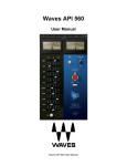
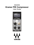
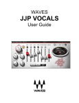
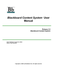
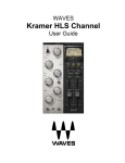
WAVES
CLA-3A
User Manual
TABLE OF CONTENTS
CHAPTER 1 – INTRODUCTION................................................................................................................................3
1.1 WELCOME...........................................................................................................................................................3
1.2 PRODUCT OVERVIEW ..........................................................................................................................................3
1.3 ABOUT THE MODELING ........................................................................................................................................4
1.4 COMPONENTS .....................................................................................................................................................5
CHAPTER 2 – QUICKSTART GUIDE .......................................................................................................................6
CHAPTER 3 – INTERFACE AND CONTROLS.........................................................................................................7
3.1 CLA-3A INTERFACE ............................................................................................................................................7
3.2 CLA-3A CONTROLS ............................................................................................................................................8
CHAPTER 4 – THE WAVESYSTEM .......................................................................................................................11
4.1 THE WAVESYSTEM TOOLBAR ............................................................................................................................11
Toolbar Functions.............................................................................................................................................................. 11
4.2 PRESET HANDLING ............................................................................................................................................11
Preset Types ..................................................................................................................................................................... 11
Loading Presets and Setups.............................................................................................................................................. 12
Saving Presets and Setups ............................................................................................................................................... 12
Deleting Presets ................................................................................................................................................................ 13
A/B Comparison and Copying ........................................................................................................................................... 13
4.3 INTERFACE CONTROLS ......................................................................................................................................13
Toggle Buttons .................................................................................................................................................................. 14
Value Window Buttons ...................................................................................................................................................... 14
Sliders ............................................................................................................................................................................... 14
Hover Box.......................................................................................................................................................................... 14
TAB Functions ................................................................................................................................................................... 15
APPENDIX A – CLA-3A CONTROLS .....................................................................................................................16
Waves CLA-3A User Guide
2
Chapter 1 – Introduction
1.1 Welcome
Thank you for choosing Waves! In order to get the most out of your Waves processor, please take the
time to read through this manual.
In conjunction, we also suggest that you become familiar with www.wavesupport.net. There you will find
an extensive Answer Base, the latest Tech Specs, detailed Installation guides, new Software
Updates, and current information on Authorization and Registration.
By signing up at www.wavesupport.net, you will receive personalized information on your registered
products, reminders when updates are available, and information on your authorization status.
1.2 Product Overview
The CLA-3A is modeled on an acclaimed solid-state compressor originally introduced in 1969. Like its
tube-based predecessor, the inspiration for the CLA-3A featured a simple control set, the T4 optical
attenuator for gain reduction, and powerful program-dependent compression characteristics. Embraced
by engineers and producers the world over due to their unmistakable compression behaviors and
unique sonic signatures, the original hardware units are widely used to this day.
Chris Lord-Alge considers these among his favorites of all vintage compressors.
About Chris Lord-Alge
Grammy®-winner Chris Lord-Alge is the mixing engineer of choice for pop and rock royalty.
Green Day | U2 | Dave Matthews Band | Daughtry | Pink | Leona Lewis | Avril Lavigne |
My Chemical Romance | All American Rejects | Nickelback | Rob Thomas | Snow Patrol |
Ray LaMontagne | Miley Cyrus | Jonas Bros. | Tim McGraw | Faith Hill | Tina Turner | Rod Stewart |
Celine Dion | Santana | Steve Winwood | James Brown
For almost thirty years, Chris has energized the sound of popular music. His hard-hitting mixes have
transformed the radio soundscape, and introduced a new sonic vocabulary along the way. CLA’s
massive hardware arsenal includes racks and racks of the most coveted compression units in music
history.
Waves CLA-3A User Guide
3
Widely known among audio pros and listeners alike for his punchy sound and extreme compression
techniques, Chris gave us exclusive access to model his most prized processors, and worked closely
with Waves through every phase of development. Together with many of his personal presets, these
precision models deliver the distinctive sound of CLA’s favorite classic compressors.
1.3 About the Modeling
Many different elements contribute to the unique sonic behavior of analog gear. Waves painstakingly
modeled and incorporated the characteristics of the hardware into the CLA-3A, in order to fully capture
and replicate the sound and performance of the original equipment. The hardware was modeled at
reference levels of -18 dBFS = +4 dBu, meaning that a signal of -18 dBFS from the DAW to the
hardware unit will display a meter reading of 0 VU (+4 dBu).
These are some of the most important elements of the CLA-3A’s analog behavior:
• Total Harmonic Distortion
Perhaps the most important analog behavior is Total Harmonic Distortion or THD, which is defined
as the ratio of the sum of the powers of all harmonic components to the power of the fundamental
frequency. THD is usually caused by amplification, and changes signal shape and content by
adding odd and even harmonics of the fundamental frequencies, which can change the overall tonal
balance. THD can also change peak output gain, usually by no more than +/- 0.2-0.3 dB.
• Variable Release Times
In the original modeled hardware, a T4 optical device determines compression behavior. When
strong signals are introduced to the compressor input, release time constants lasting several
seconds may result. In certain cases, this may cause the same passage to sound different during
successive playbacks, as the Release does not return to the unity position. This behavior is
identical to that of the original hardware, and should not be a cause for concern.
• Hum
Waves modeled both 50Hz power current and 60Hz power current. If you listen closely, you will
hear that there is a difference in hum level between 50Hz and 60Hz. Since hum is unique to each
region and dependent upon the local electrical conditions, you may find that the modeled hum is
different than the hum already present in your studio, and may not be suitable for your particular
use.
Waves CLA-3A User Guide
4
• T4
In the original hardware units, the T4 optical device is responsible for the amount of overall
compression and compression characteristics. These components are quite vulnerable to wear and
tear, and need to be replaced, ideally, every 2 to 3 years. Depleted T4 devices result in up to 80%
less compression as compared to newer components. In the course of our research, we discovered
that up to 90% of T4 components in use today have never been replaced. This means that the
majority of users are working with devices that compress far below the original manufacturer
specifications.
If you are used to the performance and behavior of an original unit, and find that the modeled plugin provides more aggressive compression than you are used to, it may be that you have grown
accustomed to a worn-out T4 component.
1.4 Components
WaveShell technology enables us to split Waves processors into smaller plug-ins, which we call
components. Having a choice of components for a particular processor gives you the flexibility to
choose the configuration best suited to your material.
The CLA-3A has two component processors:
CLA-3A Stereo – Two channel compressor, with one detector for both channel paths
CLA-3A Mono – One channel compressor
Waves CLA-3A User Guide
5
Chapter 2 – Quickstart Guide
The CLA-3A offers 2 main controls for compression, as well as additional controls for fine-tuning.
•
Using the Compress/Limiter toggle, select Compressor (approximately 3:1 ratio) or Limiter
(approximately 100:1 ratio).
•
Use the Peak Reduction control to set the amount of compression desired.
•
Use the Gain control to adjust make up level after the compression.
•
Use the VU Meter to monitor Input, Output, and Gain Reduction levels.
Waves CLA-3A User Guide
6
Chapter 3 – Interface and Controls
3.1 CLA-3A Interface
Waves CLA-3A User Guide
7
3.2 CLA-3A Controls
Gain controls the output level of the audio path.
Range: 0 to 10 (in 0.01 steps)
Initial Value: 5.50
Reset Value: 4.08 (unity gain)
Peak Reduction controls the amount of signal compression.
Range: 0 to10 (in 0.01 steps)
Initial Value: 4.00
Reset Value: 0
Please note: The scale is not linear and has been adjusted to conform to the exact scaling of
the modeled unit. Thus, there may be more compression than expected at certain steps, as with
analog gear.
Waves CLA-3A User Guide
8
Compressor Mode selects compression or limiting.
Range: Comp, Limiter
Default: Comp
HiFreq increases voltage amplifier gain in the peak reduction circuit, for frequencies above
1 kHz, leaving lower frequencies unaffected. When set to Flat, the CLA-3A will provide equal
reduction to all frequencies. The more you move away from the Flat position, the more sensitive
the compressor is to higher frequencies, resulting in heavier compression. This control may also be
used as sort of a de-esser.
Range: 0 to 100 (in 0.1 steps)
Initial Value: 50.00
Reset Value: 100 (flat)
Analog controls analog characteristics caused by noise floor and hum, based on the power
supplies of the original units.
Range: Off, 50Hz, 60Hz
Initial Value: 60Hz
Reset Value: Off
Waves CLA-3A User Guide
9
VU Display toggles between Input, Gain Reduction, and Output monitoring.
Range
In, GR, Out
Default
GR
Waves CLA-3A User Guide
10
Chapter 4 – The WaveSystem
4.1 The WaveSystem Toolbar
All Waves processors feature the WaveSystem toolbar which takes care of most administrative
functions you will encounter while working with your Waves software. The features of the WaveSystem
toolbar are the same on practically all Waves processors, so familiarity with its features will be helpful
whichever processor you are using.
Toolbar Functions
Undo
Redo
Setup A/B
Copy A->B
Load
Save
?
Undoes the last 32 actions.
Redoes the last 32 undone actions.
Toggles between two presets. This is useful for close comparison of different parameter
settings
Copies the current settings to the second preset register
Recalls presets from file
Saves presets in the Waves file formats
Opens the manual for the processor you are using.
4.2 Preset Handling
Preset Types
Factory Presets are permanent presets in the Load menu. Factory presets cannot be over-written or
deleted. When applicable, different component plug-ins may have different factory presets.
User Presets are your favorite settings of the plug-in saved as a preset in the Load menu, under ‘User
Presets’. User Presets can be over-written and deleted.
Setup Files may contain more than one preset. For example, a single file can contain all the presets for
a session. When you open a Setup File, all its setups become part of your Load pop-up menu for fast
access. This can be particularly useful with multiple instances of a plug-in in a single session. By saving
all the settings you create into a single Setup File, they can all be quickly available for every instance of
that plug-in.
Waves CLA-3A User Guide
11
Loading Presets and Setups
Click-and-hold on the Load button to see the Load pop-up menu. The menu is divided into four
sections. If a section is not currently available it will not appear in the Load pop-up menu.
Open Preset File… Select to open any setup or preset file, whether from the Library or your own
creations.
‘Filename.xps’:
Displays any currently loaded Setup File and its presets.
Factory Presets:
Displays the default Factory Presets.
User Presets:
Displays any loaded User Presets.
Saving Presets and Setups
Click-and-hold on the Save button to see the Save pop-up menu. Four options are available. If an
option is not currently available it will be grayed out and inaccessible.
Save to New File…
Select this to start a new Setup file. There are two prompts - first
for the setup filename, then for the preset name. You must provide
a name for both the setup file and the preset. Click OK (ENTER)
to complete the save. It is a good idea to create a folder in which
to save several setup files for a project.
Save ‘File Name’ – “Preset Name” Overwrites the settings of the loaded preset (whether a User
Preset or a preset from a Setup File) with the current settings. If a
Setup File is currently loaded, the name of the Setup File is
displayed followed by the name of the preset itself. If a User
Preset is loaded, its name is displayed.
Save to ‘File Name’ As…
Saves the current settings as a new preset into the Setup file that
is open (if one is not open, the option is grayed out). You will be
prompted to give the preset a name.
Put into Preset Menu As…
Save the current settings into a User Preset that will always be in
your Load menu (until deleted). You will be prompted to give this
preset a name. User Presets are stored in the plug-in’s preference
file.
Waves CLA-3A User Guide
12
Deleting Presets
You may delete User Presets and presets within a Setup File. Factory Presets and Setup Library files
cannot be deleted or overwritten.
1. Hold the Command (Mac)/Control (PC) key down.
2. Click-and-hold the Load button to see the pop-up menu.
3. While still holding the Command/Control key, select the preset or setup to delete.
4. A confirmation box will appear, allowing you to cancel or ‘OK’ the deletion.
A/B Comparison and Copying
The Setup A/Setup B button may be clicked to compare two settings. If you load a preset in the Setup B
position, this will not affect the preset loaded into the Setup A position, and vice-versa.
If you want to slightly modify the settings in Setup A, you can copy them to Setup B by clicking on the
Copy to B button, then alter Setup A and compare with the original Setup B.
The name of the current setup will be shown in the title bar (on platforms which support it), and will
switch as you change from Setup A to Setup B.
Note: an asterisk will be added to the preset name when a change is made to the preset.
4.3 Interface Controls
Controls can be in one of three states:
•
•
•
Not Selected where the control is not the target of any user entry
Selected where the control is the target of mouse control entry only
Selected and Active where the control is the target for both mouse and keyboard entry
Waves CLA-3A User Guide
13
Toggle Buttons
Toggle buttons display the state of a control, and allow switching between two or more states. Singleclick to change the control’s state. Some toggle buttons have a text display which updates with the
current setting, and others (bypass, solo, or monitoring toggles) illuminate when the control is active.
Some processors have link buttons between a pair of toggle buttons, allowing click-and-drag
adjustment while retaining the offset between the controls.
Value Window Buttons
Value windows display the value of a control and allow click-and-drag adjustment, or direct control
via the keyboard.
•
•
•
Using the mouse, click-and-drag on the value window to adjust. Some value windows support
left/right, some up/down (as you hover over a button, arrows will appear to let you know which
direction of movement that button supports).
Using the arrow keys, click once with mouse to select the button, and then use up/down –
left/right (depending on the direction supported by that button) to move in the smallest
incremental steps across the button’s range (holding down the arrow keys will move faster
through the range).
Using key entry, double click on the button to open the value window, and directly enter the
value from your keyboard. If you enter an out of range number, the button stays selected but
remains at the current setting (system beeps? If system sounds are on?)
Some processors have link buttons between a pair of value windows, allowing click-and-drag
adjustment while retaining the offset between the controls.
Sliders
Click on the slider itself or anywhere within the sliders track. The numerical value of the slider settings
is displayed in a hover window above the slider path.
Hover Box
Hovering boxes will appear and display the control value when hovering with the mouse over the
control.
Waves CLA-3A User Guide
14
TAB Functions
TAB moves the ‘selected’ status to the next control, with shift-TAB moving in the reverse direction.
Additionally, the Mac has an option-TAB function for ‘down’ movement and shift-option-TAB for ‘up’
movement where applicable.
If you have several Value Window Buttons selected, TAB functions will take you through the selected
controls only.
Waves CLA-3A User Guide
15
Appendix A – CLA-3A Controls
Control
Gain
Range
0-10 (0.01 steps)
Peak Reduction
0 to 10 (0.01 steps)
HiFreq
0-100 (0.1 steps)
Compressor Mode
Analog
Comp, Limiter
Off, 50Hz, 60Hz
VU Display
In, GR, Out
Waves CLA-3A User Guide
16
Default
Initial Value: 5.50
Reset Value: 4.08 (unity gain)
Initial Value: 4.00
Reset Value: 0
Initial Value: 50
Reset Value: 100
Comp
Initial Value: 60Hz
Reset Value: Off
GR