1
HEAD OFFICE
INMOTION AB
Solkraftsvägen 13
SE-135 70 Stockholm
SWEDEN
Telephone: +46 (0)8 682 64 00
Telefax: +46 (0)8 682 65 80
http://www.inmotech.com
SimPL
A Tool for programming the DMC
APPLICATIONS CENTERS
FRANCE
ACC Motion
BP 49
FR-95132 Franconville Cedex
Telephone: +33 (0)4 72 47 09 17
Telefax:
+33 (0)4 72 47 06 73
GREAT BRITAIN
ACC Motion
Bridge Mills, Holmfirth
Huddersfield
W. Yorkshire, HD7 2TW
Telephone: +44 (0)1484 68 83 25
Telefax:
+44 (0)1484 68 83 26
GERMANY
ACC Motion GmbH
Zähringerstrasse 23
DE-77654 Offenburg
Telephone: +49 (0)781 919 08-0
Telefax:
+49 (0)781 919 08-29
ITALY
ACC Motion Srl
c/o Fluke Slr
Viale delle Industrie 11
IT-20090 Vimodrone (MI)
Telephone: +39 02 25 00 161
Telefax:
+39 02 25 00 450
SWEDEN
Inmotion Technologies AB
Solkraftsvägen 13
SE-135 70 Stockholm
Telephone: +46 (0)8 682 64 00
Telefax:
+46 (0)8 682 65 80
User's Manual 1.1
Inmotion Technologies AB
Box 195
SE-234 23 Lomma
Telephone: +46 (0)40 41 48 50
Telefax: +46 (0)40 41 48 55
SWITZERLAND
ACC Motion SA
Wehntalerstrasse 6
CH-8154 Oberglatt
Telephone: +41 (0)1 851 5010
Telefax: +41 (0)1 851 5020
ACC Motion SA
Zone industrielle la Rippe
CH-1303 Penthaz
Telephone: +41 (0)21 863 6464
Telefax:
+41 (0)21 863 6479
U.S.A.
Inmotion Technologies
211 Overlock Drive
Sewickley, PA 15143-2305
Telephone: +1 (412) 749 0710
Telefax:
+1 (412) 749 0705
Art.No. 9032 0026 06 (c)
08 June 2000
Inmotion Technologies AB
Stockholm, Sweden
© Inmotion Technologies AB, 2000.
All rights reserved.
TABLE OF CONTENTS
2
User's Manual 1.1
Doc. No.9032 0026 06 (c) Rev. 08 June 2000
Inmotion Technologies AB
Table of Contents
Table of Contents...............................................................................3
Installation ..........................................................................................7
System requirements .............................................................................................7
Installation procedure.............................................................................................7
Getting started....................................................................................9
An example application..........................................................................................9
Starting a new application......................................................................................9
Selecting the Motor and DMC..............................................................................10
Setting Servo Gains .............................................................................................11
Assigning Digital Inputs........................................................................................11
Assigning Digital Outputs.....................................................................................12
Defining Application Units ....................................................................................13
Setting EStop / Fault Parameters ........................................................................13
Building the Program ...........................................................................................14
Configuring Program Execution...........................................................................17
Generating and Downloading the Application......................................................17
Testing the Application.........................................................................................18
File menu .........................................................................................19
The file menu .......................................................................................................19
New Application ...................................................................................................19
Open Application..................................................................................................19
Save Application ..................................................................................................19
Save Application As .............................................................................................20
Edit Application Description .................................................................................20
Print Application Summary...................................................................................20
Printer Setup ........................................................................................................20
Exit .......................................................................................................................20
Hardware menu................................................................................21
General ................................................................................................................21
Drive/Motor Selection...........................................................................................21
DMC Model Selection.......................................................................................22
Motor Model Selection......................................................................................22
DMC Option Cards ...........................................................................................22
Adding a New Motor.........................................................................................22
Resolver Settings.................................................................................................23
Primary Resolver Excitation .............................................................................23
Enabling a Secondary Resolver .......................................................................23
Secondary Resolver Poles ...............................................................................23
Master / Slave Settings ....................................................................................24
Servo Parameters ................................................................................................24
Basic and Advanced Parameters.....................................................................24
Regulator Modes ..............................................................................................24
PID Parameters................................................................................................25
Feed Forward Parameters ...............................................................................25
Torque Limit Parameters..................................................................................26
Loading Default Servo Parameters ..................................................................26
Application Units ..................................................................................................26
Position Units ...................................................................................................27
Velocity Units....................................................................................................27
Resolver Count Conversions............................................................................27
Input Assignment .................................................................................................28
User's Manual 1.1
Doc. No.9032 0026 06 (c), Rev. 08 June 2000
Inmotion Technologies AB
3
TABLE OF CONTENTS
Home Registration Input (HSI Input) ................................................................29
Option A function..............................................................................................29
Feedrate Override Input ...................................................................................29
Zero Position Input ...........................................................................................30
Emergency Stop Input......................................................................................30
Negative Limit Input..........................................................................................30
Positive Limit Input ...........................................................................................30
Program Select Line Inputs ..............................................................................30
Program Initiate Input .......................................................................................30
Index Select Line Input.....................................................................................30
Index Initiate Input ............................................................................................30
Jog Slow Input..................................................................................................30
Jog Negative Input ...........................................................................................31
Jog Positive Input .............................................................................................31
Home Initiate Input ...........................................................................................31
User Input .........................................................................................................31
Output Assignments.............................................................................................31
Home Complete Output....................................................................................32
Fault Output......................................................................................................32
In Motion Output...............................................................................................32
Position Error Output........................................................................................32
Program Running Output .................................................................................32
Ready Output ...................................................................................................32
Travel Limit Output ...........................................................................................32
Resolver Error Output ......................................................................................32
Enable Output ..................................................................................................33
User Output ......................................................................................................33
Functions menu................................................................................35
General ................................................................................................................35
Emergency Stop / Fault Parameters....................................................................35
Fault Deceleration ............................................................................................36
Position Error Limit ...........................................................................................36
Error Reset Input/Register................................................................................36
Position Activated Outputs...................................................................................36
Homing (HSI Input 1) ...........................................................................................37
Jogging.................................................................................................................38
Analog Override ...................................................................................................38
Index Moves.........................................................................................................39
Index Select Line Mode....................................................................................39
Using The Index Table Editor...........................................................................40
Cam menu........................................................................................41
General ................................................................................................................41
How Cams Work in the DMC ...............................................................................41
New Cam .............................................................................................................41
Using the Cam Editor...........................................................................................41
Cam Number ....................................................................................................42
Cam Name .......................................................................................................42
Cam Modes ......................................................................................................42
Cam Points .......................................................................................................43
Cam Input Range .............................................................................................43
Cam Output Range ..........................................................................................43
Editing Cam Point Values.................................................................................43
Importing Cam Files .........................................................................................44
Exporting Cam Files .........................................................................................44
4
User's Manual 1.1
Doc. No.9032 0026 06 (c) Rev. 08 June 2000
Inmotion Technologies AB
Deleting a Cam.................................................................................................44
Program menu .................................................................................45
General ................................................................................................................45
Redefine Registers ..............................................................................................45
Program Execution Control..................................................................................46
Program Select Line Mode...............................................................................46
Main loop, Auto Run Program ..........................................................................46
New Program .......................................................................................................46
New PL2 Program................................................................................................47
Using the SimPL Program Editor.........................................................................47
Program Number..............................................................................................47
Program Name .................................................................................................48
Selecting Program Commands ........................................................................48
Setting Program Command Parameters ..........................................................48
Deleting a Program ..........................................................................................49
Using the PL2 Program Editor .............................................................................49
Generate menu ................................................................................51
General ................................................................................................................51
Verify Setup .........................................................................................................51
Generate and Compile.........................................................................................51
Download to DMC................................................................................................51
Save, Generate, Download, Run5 .......................................................................52
Tools menu ......................................................................................53
General ................................................................................................................53
Communication Settings ......................................................................................53
Node Search ........................................................................................................54
Get Version Information from DMC .....................................................................54
Register Monitor...................................................................................................55
Application Trace .................................................................................................55
Register Utilities ............................................................................................ ...56
Run Time Utilities.................................................................................................57
Run 1 (Normal Operation) ................................................................................57
Run 2 (Store EEPROM Registers)...................................................................58
Run 3 (Copy Regulator to EEPROM and Store) ..............................................58
Run 4 (Perform Motor-Resolver Alignment).....................................................58
Run 5 (Restore Application Default Values).....................................................58
Terminal ...............................................................................................................59
Reset DMC ..........................................................................................................59
Program commands.........................................................................61
General ................................................................................................................61
DMC front panel LED definitions ......................................................67
Led definitions......................................................................................................67
Application Program structure ..........................................................69
General ................................................................................................................69
Program Execution ..............................................................................................70
STATES diagram .................................................................................................71
Application Program Timing.................................................................................72
EEprom definition.............................................................................73
User's Manual 1.1
Doc. No.9032 0026 06 (c), Rev. 08 June 2000
Inmotion Technologies AB
5
TABLE OF CONTENTS
General ................................................................................................................73
6
User's Manual 1.1
Doc. No.9032 0026 06 (c) Rev. 08 June 2000
Inmotion Technologies AB
Installation
SYSTEM REQUIREMENTS
The following hardware and software is required for proper installation and
operation of SimPL:
•
•
•
•
PC running Windows 95 or 98.
5 MB Free Disk Space.
1 Free Serial Port.
DMC Digital Motion Controller with Programming Cable.
INSTALLATION PROCEDURE
To install SimPL:
1. Insert the SimPL installation disk, labeled “Disk 1/3” into the floppy drive.
2. From Windows, run A: SETUP.EXE (B: SETUP.EXE).
3. Follow the directions given in the setup program.
If you use the CD ROM User's Manual:
1. Click on INSTALLATION at the SimPL page.
2. Follow the directions given in the setup program.
When the installation is completed, a program group named “Inmotion” and
program icon labeled “SimPL” will be created. To start SimPL, double-click on the
SimPL icon.
User's Manual 1.1
Doc. No.9032 0026 06 (c), Rev. 08 June 2000
Inmotion Technologies AB
7
8
User's Manual 1.1
Doc. No.9032 0026 06 (c), Rev. 08 June 2000
Atlas Copco Controls AB
Getting started
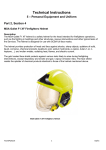
AN EXAMPLE APPLICATION
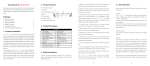
To help get started using SimPL, an example application will be examined,
illustrating step by step, how SimPL can be used to realize a system. The example
application is a linear actuator that is controlled via digital I/O. Digital inputs will be
used to command the actuator to move between its home position and a fixed
destination position. Digital outputs will indicate when the actuator is at home or its
destination position. Also included is a ready output that will indicate when the
DMC is enabled and ready to accept commands. A diagram showing the details of
the system is shown in Figure 1 below.
Figure 1. Example application diagram.
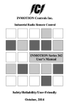
STARTING A NEW APPLICATION
To start a new SimPL application, select the New Application option from the File
menu. A dialog will appear asking for a file name to use for the new application. An
example of this file dialog is shown in Figure 2. For this example, the name
EXAMPLE.DMC has been selected. After the file name is chosen, it will be
displayed in the caption of the SimPL main form.
User's Manual 1.1
Doc. No.9032 0026 06 (c), Rev. 08 June 2000
Inmotion Technologies AB
9
GETTING STARTED
Selecting the Motor and DMC
Figure 2. New application file dialog.
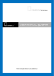
SELECTING THE MOTOR AND DMC
After starting the new application, the next step is to define what hardware is being
used in the application. At this point, the motor model and DMC model should be
selected from the database provided with SimPL. To do this click on the Drive /
Motor Selection option from the Hardware menu. The form shown in Figure 3 is
displayed.
Figure 3. Drive/motor selection form.
Select the DMC and motor model from the drop down lists on the form. Also
included on this form is a section for selecting any option cards that are installed in
the DMC. For this example no option card is used.
10
User's Manual 1.1
Doc. No.9032 0026 06 (c), Rev. 08 June 2000
Inmotion Technologies AB
GETTING STARTED
Setting Servo Gains
SETTING SERVO GAINS
To enable testing of the system an initial set of servo regulator gains must be
selected. For each motor and drive combination in the database, a set of default
gains is provided. While these gains may not give optimum performance, they will
offer an initial starting point with stable operation. To load default parameters, click
on the Servo Parameters option of the Hardware menu. The form shown in Figure
4 is displayed. To load default values, click on the Load Defaults button.
Figure 4. Servo parameters form.
ASSIGNING DIGITAL INPUTS
In the diagram of the system shown in there are a total of 6 digital inputs required.
Assigning names and functions to the digital inputs is accomplished by selecting
the Input Assignment option from the Hardware menu. The Input Assignment form,
shown in Figure 5 is displayed.
User's Manual 1.1
Doc. No.9032 0026 06 (c), Rev. 08 June 2000
Inmotion Technologies AB
11
GETTING STARTED
Assigning Digital Outputs
Figure 5. Input Assignment form.
Three of the input functions, positive limit, negative limit and Emergency Stop
input, are directly supported by SimPL and need only to be assigned to a digital
input. To assign a pre-defined function to an input, select an entry from the drop
down list associated with the input. The other two inputs are to be used in the
program to perform specialized tasks. In the case of these inputs, the input function
is set to User Input and a meaningful User Name is assigned. These inputs will be
checked and acted upon using commands in the program.
ASSIGNING DIGITAL OUTPUTS
For the example application there are a total of 3 digital outputs required. Assigning
names and functions to the digital outputs is accomplished by selecting the Output
Assignment option from the Hardware menu. The Output Assignment form, shown
in Figure 6 is displayed.
Figure 6. Output Assignment form.
12
User's Manual 1.1
Doc. No.9032 0026 06 (c), Rev. 08 June 2000
Inmotion Technologies AB
GETTING STARTED
Defining Application Units
The Output Assignment form is similar to the Input Assignment form described
above. The Ready Output function is a predefined function and is assigned using
the drop down list. The other two outputs have specialized functions and are setup
as User Outputs with meaningful names. These outputs will be controlled by
program commands defined later.
DEFINING APPLICATION UNITS
Now that the hardware being used is defined, the next step is to define the units to
be used when entering motion related parameters. Since SimPL allows position
and velocity units to be arbitrarily defined, a conversion factor between motor
revolutions and the position/velocity units must be defined. This is accomplished by
selecting the Application Units options from the Hardware Menu. The Application
Units form is shown in Figure 7 below.
Figure 7. Application units form.
In the example application, the position units are to be defined in inches. Since a
gear reducer with a 5:1 reduction is being used to drive a belt system driven by 2.5
inch diameter pulleys, the conversion factor is found to be:
Position Units per Motor Revolution = 2.5 in x π ÷ 5 = 1.570795 in.
The velocity units for the example are inches per second. As with the position
units, a conversion factor must be entered for the velocity units. The conversion
factor is found to be:
Velocity Units per 1000rpm = 1000rpm ÷ 60sec × 2.5in x π ÷ 5 = 26.18 in/sec.
Now that these conversions have been entered, it is possible to enter positions and
distances in inches and velocities in inches per second.
SETTING ESTOP / FAULT PARAMETERS
The application generated by SimPL contains extensive error handling and
detection routines to respond to a variety of fault conditions. Some of these
routines require parameters specific to the application itself. These parameters are
entered using the EStop / Fault Parameters form displayed in Figure 8 below. To
access this form, select the EStop / Fault Parameters option from the Functions
menu.
User's Manual 1.1
Doc. No.9032 0026 06 (c), Rev. 08 June 2000
Inmotion Technologies AB
13
GETTING STARTED
Building the Program
Figure 8. Fault parameter form.
The first parameter to be entered is a fault deceleration. This is used to set the rate
(deceleration) at which the motor comes to a stop when an EStop/Fault occurs,
such as a limit switch being activated.
The second of these parameters is the Position Error Limit. This defines the
maximum error that may exist between the desired motor position and the actual
motor position. If this value is ever exceeded, the DMC will disable output power to
the motor and indicate an error on the front panel LED’s. A position error can occur
for many reasons and is a good indication of a mechanical or electrical failure. For
this example, the position error limit has been set to 0.25 inches.
Once motion has ceased, the DMC digital outputs are modified according to the
options selected on this form. If a particular output should be turned on or off after
an emergency stop, simply select that state for the output. If no change is desired,
click on the “No Change” option for that output.
BUILDING THE PROGRAM
After all hardware, input functions and output functions are defined, the actual
program, which will be operating in the DMC, must be defined. To add a new
program to the application, select the New Program option from the Program
menu.
A SimPL Program Editor form will be displayed. On this form are places to enter
the program name and number. For this example, the program number is set to
zero and the program name is set to “Main Example Program”. Since SimPL can
support up to 32 different programs in the same application, it is necessary to give
each program a unique number. The program name is set to make it easier to
identify programs by a name, in addition to a number. The example application
being discussed here is very basic and has only one program.
Figure 9 shows the program used in this application to move the linear actuator in
response to the digital input commands. It also includes the commands to control
the digital outputs, which indicate the current position of the actuator.
Line 12 of the program is not visible but contains a Jump command to go back to
line 2.
14
User's Manual 1.1
Doc. No.9032 0026 06 (c), Rev. 08 June 2000
Inmotion Technologies AB
GETTING STARTED
Building the Program
Figure 9. SimPL program editor form.
To define a program line in SimPL, double click on the desired cell in the
Command column of the grid. If adding a line to the end of the program, double
click on the blank command line at the end of the program. To insert a line, click on
the line of the program to come after the new line, either press the <Insert> key or
select Insert from the Edit menu.
After double clicking on a cell in the Command column, a form will appear, showing
all available program commands that may be selected. This form is shown in
Figure 10.
Figure 10. Select new command form.
After selecting a command from the list, the new command name will be displayed
in the program grid. The Command Parameters cell for this program line will
indicate that the parameters are not yet defined. To define the parameters, doubleclick on the Command Parameters cell of the desire program line to display the
command parameter form. For example, when defining the Set Output Pattern
command in line 5, the parameter form shown in Figure 11 is displayed.
User's Manual 1.1
Doc. No.9032 0026 06 (c), Rev. 08 June 2000
Inmotion Technologies AB
15
GETTING STARTED
Building the Program
Figure 11. Set output pattern parameters form.
This command allows the state of all digital outputs to be defined in a single
command. As shown Figure 11, this command will turn off the “At Home” and the
“At Position” outputs and leaves all others unaffected.
The above procedure of selecting a command and setting its parameters is
repeated, until the program is complete. Below in Table 1 is a description of each
of the program lines in the example program.
Line
16
Command
Purpose
1
Home
Searches for the Home input in the negative
direction and sets the position of the sensor
to zero.
2
Jump on Input
If “Goto Home” input is on then jump to line 5,
where the commands to set the digital
outputs and the command to move to the
zero position are located.
3
Jump on Input
3 If “Goto Position” input is on then jump to
line 9, where the commands to set the digital
outputs and the command to move to the
destination position are located.
4
Jump
Go back to line 2 to check the inputs again
5
Set Output Pattern
Turn off the “At Home” and “At Position”
outputs, since the actuator is about to be
moved.
6
Move Absolute
Move the actuator to the home position.
7
Set Output
Turn on the “At Home” output, since the
actuator is now at the home position.
8
Jump
8 Go back to line 2 and wait for the next input
command.
9
Set Output Pattern
Turn off the “At Home” and “At Position”
outputs, since the actuator is about to be
moved.
10
Move Absolute
Move the actuator to the destination position
of 10 inches from home.
User's Manual 1.1
Doc. No.9032 0026 06 (c), Rev. 08 June 2000
Inmotion Technologies AB
GETTING STARTED
Configuring Program Execution
Line
Command
Purpose
11
Set Output
Turn on the “At Position” output, since the
actuator is now at the destination position.
12
Jump
Go back to line 2 and wait for the next input
command.
Table 1. Program commands
CONFIGURING PROGRAM EXECUTION
After the program is defined, it is necessary to select how and when the program
will be executed. This selection is made using the Program Execution Control
option of the Programs Menu. When this option is selected, the form shown in
Figure 12 is displayed.
Figure 12. Program execution control form.
On the form is a section for select line mode. This only applies in the case where
digital input lines are used to select and start execution of different programs. In
this example, no such input lines are defined. Instead, the program is setup to
execute automatically, whenever the DMC is powered up and enabled. To set a
program to be automatically executed, select it from the drop down list labeled
“Main loop, Auto-Run Program”.
GENERATING AND DOWNLOADING THE
APPLICATION
Now that the application is fully defined, it is necessary to generate and compile
the code that will be executed in the DMC.
This is accomplished by selecting the Generate and Compile option from the
Generate Menu. There are two options presented when selecting this menu item. If
the DMC contains a battery-backed RAM, the program can be downloaded over an
RS232 line. In this case, select the Generate and Compile for Download option. If
the DMC is using an EPROM for program storage, select the Generate for EPROM
option to create a file that can be sent to an EPROM programmer. In this example,
it is assumed that a battery-backed RAM module is installed in the DMC.
User's Manual 1.1
Doc. No.9032 0026 06 (c), Rev. 08 June 2000
Inmotion Technologies AB
17
GETTING STARTED
Testing the Application
After a generate option is selected, the application is checked to make sure that all
parameters are valid and all required setting are made. If an error is detected, a
window will be displayed showing all warnings and errors that were found. If the
application is verified, the application code will be generated and compiled.
Refer to Verify Setup for a complete description. After the application has been
successfully generated, it must be downloaded to the DMC. This is accomplished
by selecting the Download to DMC option from the Generate menu. When this
option is selected, a form will appear showing the file to be downloaded. Please
refer to Download to DMC for a complete description.
TESTING THE APPLICATION
To test the application, the DMC must be reset. This can be done by cycling power
to the DMC or by selecting the Reset DMC option from the Tools menu. Once this
is done, the DMC can be enabled and the program will begin to execute.
In order to observe the status of the DMC and the application it is executing, an
application trace utility is included in SimPL. To access this feature, select the
Application Trace option from the Tools menu. The Application Trace from is
shown in Figure 13 below.
Figure 13. Application trace form.
On the application trace form, the state of the digital inputs and digital outputs are
monitored. Also, the action being taken in the application is displayed. Figure 13
shows the application trace form at the time when the program is executing the
Home command and is searching for the Home Input. This utility is useful in
tracking and debugging programs as well as diagnosing faults and error conditions.
After monitoring execution and observing performance, the application can be
repeatedly changed, downloaded and tested until proper operation is achieved.
18
User's Manual 1.1
Doc. No.9032 0026 06 (c), Rev. 08 June 2000
Inmotion Technologies AB
File menu
THE FILE MENU
The File Menu contains all menu items used to load, save and print application
settings. The content of the File Menu is shown in Figure 14.
Figure 14. File menu.
NEW APPLICATION
The New Application menu item is used to start a new application with default
settings. When this menu item is selected, a file dialog is displayed. Enter a new
file name or select an existing file to overwrite. All SimPL application files have a
*.DMC file extension. All additional files generated by SimPL share the same name
but have different extensions.
OPEN APPLICATION
The Open Application menu item is used to load a previously saved application.
When this menu item is selected, a file dialog is displayed. Enter the application file
name to open. Also note that the names of the last 4 applications loaded into
SimPL are displayed at the bottom of the File menu. To re-open one of these
applications, simply select it from the list.
SAVE APPLICATION
The Save Application menu item is used to save any changes to the current
application. The application is saved to the file name displayed in caption of the
main form.
User's Manual 1.1
Doc. No.9032 0026 06 (c), Rev. 08 June 2000
Inmotion Technologies AB
19
FILE MENU
Save Application As
SAVE APPLICATION AS
The Save Application As menu item is used to save the current application under a
new name. When this menu item is selected a file dialog is displayed. Enter a new
name or select an existing file to overwrite. All subsequent files generated for this
application will use the new name.
EDIT APPLICATION DESCRIPTION
The Edit Application Description menu item is used to enter any comments
concerning the application. These comments will be included in the header of the
generated PL2 code as well as in the printed application summary. When this
menu item is selected, a form is displayed containing a small text editing area
where these comments can be entered.
PRINT APPLICATION SUMMARY
The Print Application Summary menu item is used to print summary of all settings
made for the current application. The printout will contain all settings, programs,
index moves and cams used in the application.
PRINTER SETUP
The Printer Setup menu item displays a standard printer setup dialog. This dialog
is used to change printers, printer settings, paper size and orientation.
EXIT
The Exit menu item is used to exit SimPL and return to Windows. If the current
application has changes that have not been saved, a warning will be displayed
before exiting.
20
User's Manual 1.1
Doc. No.9032 0026 06 (c), Rev. 08 June 2000
Inmotion Technologies AB
Hardware menu
GENERAL
The Hardware Menu contains all menu items used to specify and configure the
hardware used in the application, along with assignment of functionality to the
digital I/O of the system. The content of the Hardware Menu is show in Figure 15.
Figure 15. Hardware menu.
DRIVE/MOTOR SELECTION
The Drive / Motor Selection menu item is used to specify which motor, DMC model
and option card are being used in the application. When this menu item is selected,
the form shown in Figure 16 is displayed. Since multiple DMC’s can be connected
together in a daisy chain configuration, it is necessary to assign each unit a unique
hexadecimal node address. Valid node addresses are between 1 and F. To select
a new node address, pick one of the available choices from the list. This node
address is included in the generated application. Each time the DMC is powered
up or reset, it defaults to this node address and all communications must be
directed to this node address.
Figure 16. Drive/Motor selection.
User's Manual 1.1
Doc. No.9032 0026 06 (c), Rev. 08 June 2000
Inmotion Technologies AB
HARDWARE MENU
Drive/Motor Selection
DMC MODEL SELECTION
A database is included with SimPL, which contains all DMC models. This database
contains current ratings for each drive, which is critical for properly computing
default servo gains and torque limits. To select a new model, simply select an item
from the list.
MOTOR MODEL SELECTION
The database provided with SimPL also includes all of the standard motors
available from Inmotion Technologies. This database contains current ratings and
resolver parameters for each motor. To select a new motor, pick an item from the
list.
DMC OPTION CARDS
The DMC can contain an internally mounted option card. The option "O"card
provides the DMC with additional 7 digital inputs and 7 digital outputs. The Option
"A" card allows the DMC to interface with resolvers, which are not excited by a
DMC. Only select an option card if it was ordered with the DMC since these options
change the availability of certain functions.
ADDING A NEW MOTOR
If the motor to be used is not found in the current motor database, it is possible to
add a new motor. To add a motor, click on the Add Motor button to display the form
shown in Figure 17 below.
Figure 17. Add New Motor form.
Enter the proper motor parameters using this form and click on the OK button. This
new motor will be added to the list of motors and automatically selected.
22
User's Manual 1.1
Doc. No.9032 0026 06 (c), Rev. 08 June 2000
Inmotion Technologies AB
HARDWARE MENU
Resolver Settings
RESOLVER SETTINGS
The Resolver Settings menu item is used to specify which of the resolver inputs of
the DMC are used and how they are excited. When this menu item is selected, the
form shown in Figure 18 is displayed.
Figure 18. Resolver settings form.
PRIMARY RESOLVER EXCITATION
The primary resolver on the Atlas DMC is the resolver attached to the motor driven
by the DMC. {The only time this setting must be made for this resolver is if the
Option “A” card is used. If an Option “A” card is being used and the primary
resolver is being excited by an external source, select the external excitation
option}.
ENABLING A SECONDARY RESOLVER
The secondary resolver on the Atlas DMC is used to support Master/Slave
functions such as electronic gearing and position lock cam tables. If a second
resolver is not used by the application, make sure that there is no “X” in the “Use
Second Resolver” button. If the second resolver option is turned on, routines for
monitoring its amplitude are included in the generated application. These routines
will generate a fault if no second resolver is attached.
SECONDARY RESOLVER POLES
If a second resolver is used for Master/Slave functions, it is necessary to set the
number of resolver poles for the resolver. Enter the number of resolver poles in the
edit box on the form. The number of poles determines how electronic gears and
CAM functions operate. If the wrong number of resolver poles is entered, scaling of
CAM tables and electronic gearing will be computed incorrectly.
User's Manual 1.1
Doc. No.9032 0026 06 (c), Rev. 08 June 2000
Inmotion Technologies AB
23
HARDWARE MENU
Servo Parameters
MASTER / SLAVE SETTINGS
When two or more DMCs share resolvers, they must be synchronized. This is
accomplished through the sync lines located on the front panel connectors on the
DMC. These sync lines must be controlled by a single DMC. This DMC should be
designated as the Master and the others should be designated as Slaves. If a DMC
does not need to synchronize with another DMC, select the stand-alone option to
have it ignore the sync lines altogether.
SERVO PARAMETERS
The Servo Parameters menu item is used to set the default parameters used in the
DMC servo regulator. When this menu item is selected, the form shown in Figure
19 is displayed.
Figure 19. Servo parameters form.
BASIC AND ADVANCED PARAMETERS
The Servo Parameters form allows for setting all of the parameters, which control
the operation of the DMC servo regulator. When this form is displayed for the first
time, only a basic set of parameters is displayed. These parameters relate to basic
PID control functions. If desired, all servo parameters can be displayed and edited,
by clicking on the advanced button located at the bottom of the form. Operators
with a good understanding of the DMC regulator should only modify these
advanced parameters. If the advanced parameters are displayed, it is possible to
return to the basic parameter set by clicking on the Basic button.
REGULATOR MODES
The DMC servo regulator can operate in several different modes. The two primary
modes are position and speed, each with an option for using integrated error.
Depending on which of the four modes is selected; different PID parameters are
24
User's Manual 1.1
Doc. No.9032 0026 06 (c), Rev. 08 June 2000
Inmotion Technologies AB
HARDWARE MENU
Servo Parameters
used. Those parameters, which are not used, have their associated displays
disabled.
As a position regulator, the DMC computes an output torque based on both the
speed and position error of the system. This mode is used in positioning systems
where the actual position of the motor is critical. At each servo cycle, the DMC
compares the actual motor speed and position with the commanded speed and
position. These differences are then multiplied by the appropriate regulator gains to
produce the output torque to the motor. In addition to these computations, it is
possible to specify if the integral of the position error is also used in the torque
calculations. If integration is turned on, the regulator will produce increasing torque
until a zero position error is achieved. However, position error integration can also
have the effect of causing overshoot and some oscillations in the system.
Therefore this mode should be used carefully with moderate values of the integral
PID gain.
When used as a speed regulator, the DMC ignores the position error of the motor
and concentrates only on the speed error. This mode is used when the drive is
desired to run at specified speeds without regard to its actual position. In speed
regulator mode, it is also possible to use the integral of the speed error in the
output torque calculations. The use of integration in this mode increases the
holding torque of the motor.
PID PARAMETERS
There are three main parameters used in the PID control loop implemented in the
DMC. Each of these gains also has an associated error limit with it. The
Reg.PGain parameter is multiplied with the position error to generate an output
torque.
Its associated error limit Reg.PErrlim is used to limit the maximum position error
that is used in the computation. This is important in preventing saturation of the
regulator. These limits can be set manually or can be automatically computed by
SimPL to prevent saturation. To have all error limits computed automatically,
simply click on the Auto-Compute box in the PID Parameters section of the form.
The Reg.IGain parameter and its error limit parameter Reg.IErrlim are used
to compute an output torque based on integrated error values. If the DMC is using
a position regulator, the integrated position error is multiplied by this factor. If using
a speed regulator, the integrated speed error is multiplied by this factor. Because
integrated speed errors can be large, an additional parameter Reg.SiScale is
provided. This parameter is used to scale the integrated speed error by a factor of
2 -Reg.SiScale . The Reg.IErrlim parameter limits the maximum amount of
integrated error that is used in the torque computation.
The Reg.DGain parameter and its error limit Reg.DErrlim are used to compute
an output torque based on the speed error. The Reg.DErrlim parameter limits
the maximum amount of speed error that is used in the torque computation.
FEED FORWARD PARAMETERS
The DMC has several additional parameters that are useful in optimizing
performance. These parameters do not depend on speed or position errors. The
are referred to as feed forward parameters because they bypass the PID portion of
the regulator and generate a torque output based on commanded speed and
acceleration values.
User's Manual 1.1
Doc. No.9032 0026 06 (c), Rev. 08 June 2000
Inmotion Technologies AB
25
HARDWARE MENU
Application Units
The Reg.StatFric parameter adds a constant amount of output torque, based
on the sign of the commanded speed. This parameter is used to overcome a
constant frictional force on the motor. If the commanded speed is positive, a
positive offset equal to Reg.StatFric is added to the output torque. Likewise, a
negative speed command adds a negative offset.
The Reg.ViscFric parameter is used to overcome viscous friction in the
system. It produces a feed forward torque proportional to the commanded speed.
Since commanded speeds command can sometimes be large, an additional
parameter Reg.ViscSF is provided. This parameter is used to scale the
command speed by a factor of 2 -Reg.ViscSF .
There are two parameters used to compensate for system inertia. These
parameters produce a torque feed forward which is proportional to the commanded
acceleration. The parameter Reg.InertiaP affects torque when accelerating in
a positive direction and Reg.InertiaN affects torque when accelerating in a
negative direction. As with speeds, accelerations can be large, so there is a scale
factor Reg.InertSF that scales the commanded acceleration by 2 Reg.InertSF .
TORQUE LIMIT PARAMETERS
In order to prevent damage to motors, drives and mechanics it is often necessary
to limit the amount of torque-producing current that is generated by the DMC. This
is accomplished by using three parameters available in the DMC regulator.
With these parameters it is possible to set a peak torque and continuous torque
limit for the drive. The values of these parameters are set using the fact that a
torque limit of 8191 is equal to 100% of the rated peak torque of the DMC. If
desired, these values can be computed automatically by selecting the AutoCompute option in the Torque Limit section of the form. If Auto-Compute is
selected, torque limits will be set at the highest continuous and peak torque that
will not damage the DMC or the motor.
The parameter Reg.TorqLim limits the peak torque produced by the drive. This
parameter prohibits any current output greater than the amount specified in this
parameter. The parameter Reg.TorqCLim limits the continuous torque produced
by the drive. This parameter works in conjunction with the Reg.TorqTime
parameter that contains a value in milliseconds. The way the continuous torque
limit works is that the DMC is allowed to output a torque greater than
Reg.TorqClim but less than Reg.TorqLim for the number of milliseconds
stored in Reg.TorqTime. After this time has expired the torque limit is reduced to
the value stored in Reg.TorqCLim. This feature allows the peak outputs from the
drive and motor to be utilized without risk of exceeding their continuous ratings.
LOADING DEFAULT SERVO PARAMETERS
If a motor and DMC have already been selected, the Load Defaults button can be
clicked to fill the parameters with values that will ensure a good starting point for
servo loop performance. Selecting this option will set the regulator to position
regulator mode and set error limits and torque limits to auto-compute.
APPLICATION UNITS
The Application Units menu item is used to specify what system of units will be
used to enter positions, speeds and acceleration into the SimPL application. When
26
User's Manual 1.1
Doc. No.9032 0026 06 (c), Rev. 08 June 2000
Inmotion Technologies AB
HARDWARE MENU
Application Units
this menu item is selected the form shown in Figure 20 is displayed. This
application units feature permits specifying positions in any arbitrary units such as
inches, millimeters, revolutions, etc. Similarly, speeds and accelerations can also
be arbitrarily defined.
Figure 20. Application units form.
POSITION UNITS
To specify position units for the application, a label for the units must be entered,
along with the number of units per motor revolution. For example, if the motor is
attached to a screw with a 0.2 inch lead. The text “in” can be entered as the
position unit’s label and 0.2000 can be entered as the number of position units per
motor revolution. This allows all positions, distances, and cam tables to be entered
in inches. The position display format setting is used to determine how many
decimal places are to be used when entering and displaying position values. To set
the format, select an option from the pull-down list. Notice that the number of
resolver counts per units is computed and displayed on the form.
VELOCITY UNITS
To specify velocity units for the application, a label for the units must be entered,
along with the number of units per 1000 rpm. For example, if the motor is attached
to a screw with a 0.2 inch lead and velocity units of “in/min” is desired, the text
“in/min” can be entered as the velocity units label and 200 can be entered as the
number of velocity units per 1000 rpm.
This allows all speeds to be entered in “in/min”. All accelerations are as velocity
units per second. In the above example, all acceleration would be handled as
“in/min/sec”. The velocity/acceleration display format setting is used to determine
how many decimal places are to be used when entering and displaying velocity
and acceleration values. To set the format, select an option from the pull-down list
RESOLVER COUNT CONVERSIONS
Although SimPL allows motion parameters to be entered in user-defined
application units, there are cases when it is necessary to use raw positioning units
in an application. The DMC converts the analog resolver signal to resolver counts,
User's Manual 1.1
Doc. No.9032 0026 06 (c), Rev. 08 June 2000
Inmotion Technologies AB
27
HARDWARE MENU
Input Assignment
where there are 4096 counts for every resolver pole. For example, if a motor has a
two-pole resolver, each motor revolution will result in a change in position of 8192
counts. This value is important when user registers are specified for parameters in
SimPL program sequences. If the register is to contain a position, speed or
acceleration, the value contained in the register is in resolver counts, not
application units. In order to facilitate the conversion from application units to
resolver counts, the number of resolver counts per position unit and velocity units
are displayed on the Application Units form.
INPUT ASSIGNMENT
The Input Assignment menu item is used to assign names and functionality to the
available digital inputs of the DMC.
When this menu item is selected, the form shown in Figure 21 is displayed. Notice
that the form shown in Figure 21 contains standard as well as optional inputs. The
optional inputs are only available and visible when the Option “O” card is specified
in the hardware setup. Otherwise, only the standard inputs can be assigned.
Figure 21. Input Assignment form.
There are pre-defined input functions that may be assigned to digital inputs. Inputs
can also be designated as user inputs and have functionality only as they are used
in programs. If input is designated as user input, a name can be assigned to it for
easier programming.
There are limitations as to which inputs can be assigned to particular functions.
This result from the fact that only the standard DMC inputs can generate interrupts
and only digital input 1 can be used as a position capture input. Valid input
assignments are shown in Table 2, followed by a description of each of the
possible input functions.
Input Function
28
Digital Input 1
Home Registration
X
Option A function
X
User's Manual 1.1
Doc. No.9032 0026 06 (c), Rev. 08 June 2000
Standard Inputs
Optional Inputs
X
Inmotion Technologies AB
HARDWARE MENU
Input Assignment
Input Function
Digital Input 1
Standard Inputs
Optional Inputs
Program Abort
X
X
Program Pause
X
X
Feedrate Override
X
X
Zero Position
X
X
Emergency Stop
X
X
Negative Limit
X
X
Positive Limit
X
X
Program Select Line
X
X
X
Program Initiate
X
X
X
Index Select Line
X
X
X
Index Initiate
X
X
X
Jog Slow
X
X
X
Jog Negative
X
X
X
Jog Positive
X
X
X
Home Initiate
X
X
X
User Input
X
X
X
Table 2. Valid input function assignments.
HOME REGISTRATION INPUT (HSI INPUT)
The Home Registration input function captures the motor position the instant the
input is activated. This functionality is used exclusively during homing routines. If
this function is not assigned, homing will not be allowed in the application. Home
routines can be initiated either in a program or with the Home Initiate input. Refer
to Homing (HSI Input 1) for a description of how to setup the homing routine
activated by the Home Initiate input. Section Program menu described the
command used to start homing in a program.
OPTION A FUNCTION
The Option A function is used to switch between Resolver 1 and Resolver 2 Input
on the Option A card. This function is normally used to drive two motors with one
DMC and will perform a resolver calibration and a motor counter reset each time
the input changes.
FEEDRATE OVERRIDE INPUT
The Feedrate Override input is used to turn on the analog feedrate override
function. When this function is active, all velocities will be scaled according to the
voltage present at analog input 1 or 2. This scaling is setup using the form
described in Analog Override.
User's Manual 1.1
Doc. No.9032 0026 06 (c), Rev. 08 June 2000
Inmotion Technologies AB
29
HARDWARE MENU
Input Assignment
ZERO POSITION INPUT
The Zero Position input causes the current position to be automatically set to zero.
EMERGENCY STOP INPUT
The Emergency Stop input causes all motion to stop and all digital outputs to be
set to a defined state. After motion has ceased, the DMC is disabled and the motor
brake is engaged. The rate at which motion is stopped and the states of the
outputs are set using the form described in Emergency Stop / Fault Parameters.
NEGATIVE LIMIT INPUT
The Negative Limit input causes all motion to stop when activated. This input
should be used for over travel protection. After motion is stopped, the drive is
disabled and a fault is indicated. Any programs or index moves will be aborted.
POSITIVE LIMIT INPUT
The Positive Limit input causes all motion to stop when activated. This input should
be used for over travel protection. After motion is stopped, the drive is disabled and
a fault is indicated. Any programs or index moves will be aborted.
PROGRAM SELECT LINE INPUTS
The Program Select Line inputs are used to select which program is to be initiated
when the Program Initiate input is activated. Any number of digital inputs can be
assigned to this function. For more information on how these inputs functions, refer
to Section Program Execution Control
PROGRAM INITIATE INPUT
The Program Initiate input starts execution of the program designated by the
Program Select Line inputs. If a program or index move is already executing, this
input will be ignored.
INDEX SELECT LINE INPUT
The Index Select Line inputs are used to select which index move is to be initiated
when the Index Initiate input is activated. Any number of digital inputs can be
assigned to this function. For more information on how these inputs function, refer
to Section Index Moves.
INDEX INITIATE INPUT
The Index Initiate input starts execution of the index move designated by the Index
Select Line inputs. If an index move or program is already executing, this input will
be ignored.
JOG SLOW INPUT
The Jog Slow input is used to select the speed at which the DMC will jog when
either the Jog Negative or Jog Positive input is activated. If the Jog Slow input is
30
User's Manual 1.1
Doc. No.9032 0026 06 (c), Rev. 08 June 2000
Inmotion Technologies AB
HARDWARE MENU
Output Assignments
active when a jog move is started, the motor will be moved at the slow jog speed.
For more information on setting jog speeds and acceleration refer to Section
Jogging
JOG NEGATIVE INPUT
The Jog Negative input causes the DMC to jog in the negative direction. The speed
at which the motor moves is determined by the state of the Jog Slow input and the
settings entered using the form described in Section Jogging.
JOG POSITIVE INPUT
The Jog Positive input causes the DMC to jog in the positive direction. The speed
at which the motor moves is determined by the state of the Jog Slow input and the
settings entered using the form described in Section Jogging.
HOME INITIATE INPUT
The Home Initiate input causes the homing routine to be initiated. To use this
function, digital input 1 must be set as the Home Registration input. Refer to
Section Homing (HSI Input 1) for a description of the homing routine.
USER INPUT
Any of the digital inputs of the DMC can be used as user inputs. These inputs can
be assigned a name. There is no automatic functionality assigned to these inputs.
However, these inputs can be monitored and used to control program flow.
OUTPUT ASSIGNMENTS
The Output Assignment menu item is used to assign names and functions to the
available digital outputs of the DMC. When this menu item is selected, the form
shown Figure 22 is displayed. Notice that the form shown in Figure 22 contains
standard as well as optional outputs. The optional outputs are only available and
visible when the Option “O” card is specified in the hardware setup. Otherwise,
only the standard outputs can be assigned.
Figure 22. Output assignment form.
User's Manual 1.1
Doc. No.9032 0026 06 (c), Rev. 08 June 2000
Inmotion Technologies AB
31
HARDWARE MENU
Output Assignments
There are pre-defined output functions that may be assigned to digital outputs.
Outputs can also be designated as user outputs and have functionality only as they
are used in programs. If an output is designated as a user output, a name can be
assigned to it for easier programming. Below is a description of each of the output
functions that can be assigned.
HOME COMPLETE OUTPUT
The Home Complete output is activated after a homing sequence has been
successfully completed. This output is used to indicate that the DMC has an
absolute position reference.
FAULT OUTPUT
The Fault Output is activated any time a fault has occurred that results in motion
being stopped and the drive being disabled. This output will remain activated until
the fault is cleared.
IN MOTION OUTPUT
The In Motion output is activated any time the DMC is commanding a motor
velocity other than zero.
POSITION ERROR OUTPUT
The Position Error output is activated when the position error limit has been
exceeded and the drive has been disabled. The position error limit is specified
using the form described in Section Position Error Limit
PROGRAM RUNNING OUTPUT
The Program Running output is activated any time the DMC is executing a
program sequence. The output remains active even is program execution has been
paused.
READY OUTPUT
The Ready Output is activated whenever the DMC is enabled and no fault
conditions exist.
TRAVEL LIMIT OUTPUT
The Travel Limit output is activated when activation of one of the travel limit inputs
has been activated.
RESOLVER ERROR OUTPUT
The Resolver Error output is activated when the amplitude on the resolver input is
too low and the drive has been disabled.
32
User's Manual 1.1
Doc. No.9032 0026 06 (c), Rev. 08 June 2000
Inmotion Technologies AB
HARDWARE MENU
Output Assignments
ENABLE OUTPUT
The Enable output is activated 500 ms before a software power-on and deactivated
500 ms after a software power-off. This function is normally used together with the
Option A card to switch between two motors.
USER OUTPUT
Any number of the digital outputs of the DMC can be used as user outputs. These
outputs can be assigned a name. There is no automatic functionality assigned to
these outputs. However, these outputs can be controlled in programs.
User's Manual 1.1
Doc. No.9032 0026 06 (c), Rev. 08 June 2000
Inmotion Technologies AB
33
Functions menu
GENERAL
The Function Menu contains menu items that allow setup of the functionality
provided by the digital input assignments. The content of the Functions Menu is
show in Figure 23.
Figure 23. Functions menu.
EMERGENCY STOP / FAULT PARAMETERS
The EStop/ Fault Parameters menu item is used to setup the emergency stop
routine and to specify parameters to how the DMC decelerates after faults occur or
the Emergency Stop input is activated. When this menu item is selected, the form
shown in Figure 24 is displayed.
Figure 24. Emergency stop form.
Whenever the EStop input is activated or after faults occur, all motion is stopped
and the motor is decelerated using the value entered on this form. Once motion
has ceased, the DMC digital outputs are modified according to the options selected
on this form. If a particular output should be turned on or off after an emergency
User's Manual 1.1
Doc. No.9032 0026 06 (c), Rev. 08 June 2000
Inmotion Technologies AB
35
FUNCTIONS MENU
Position Activated Outputs
stop, simply select that state for the output. If no change is desired, click on the “No
Change” option for that output.
FAULT DECELERATION
The fault deceleration determines how fast the DMC decelerates when faults such
as over travel limits or over temperatures occur. Some faults such as position error
will immediately disable the drive without deceleration because they indicate
conditions where the drive is out of control and cannot be properly decelerated.
POSITION ERROR LIMIT
The position error limit setting is used to determine the maximum amount of error
between the commanded position and the actual position before a fault is
generated. Note that when the servo regulator is used in velocity mode, this
parameter is not used and position error is not monitored.
ERROR RESET INPUT/REGISTER
The error reset Input/Register is used to reset all DMC errors after a fault condition.
POSITION ACTIVATED OUTPUTS
The Position Activated Outputs menu item allows digital outputs to be activated,
deactivated or pulsed based on the position of the motor. When this menu item is
chosen, the form shown in Figure 25 is displayed.
Figure 25. Position activated outputs form.
There are four sets of conditions that can be setup. For each condition, the digital
output, transition position, transition type and action must be specified.
For example, if the application requires digital output 7 to be pulsed for 500
milliseconds every time the motor passes a position of 10 inches in the positive
direction, the settings shown in the first condition set in Figure 25 would be used.
36
User's Manual 1.1
Doc. No.9032 0026 06 (c), Rev. 08 June 2000
Inmotion Technologies AB
FUNCTIONS MENU
Homing (HSI Input 1)
Note that if the motor then passed the position of 10 inches in the negative
direction no action would be taken.
Similarly, outputs can be set to turn on or off when moving in different directions.
For example, the second and third condition sets in Figure 25 would have digital
output 5 turn on when passing 1 inch in the positive direction and turn off when
passing the same point in the negative direction.
Position activated outputs are monitored as part of a background process in the
Atlas DMC. Every 20 milliseconds, the DMC checks if the motor has passed any of
the transition positions defined for the outputs. If this has occurred, the output is
changed or pulsed based on the action selected for it. The position activated output
monitoring is active any time the drive is enabled and not in a fault condition.
It is possible to enable and disable checking of any of the four conditions within a
SimPL program sequence. It is also possible to have these conditions
automatically enabled or disabled when power is turned on to the DMC. This is
accomplished by clicking on the enabled or disabled Default State for each
condition.
HOMING (HSI INPUT 1)
The Homing menu item is used to setup the homing routine that is started using
the Home Initiate Input. When this menu item is selected, the form shown in Figure
26 is displayed.
Figure 26. Homing form.
When the homing routine is initiated, the motor begins moving in the specified
direction until the Home Registration input (HSI Input: DMC Input 1) is activated. At
this time, the motor decelerates and returns to the position at which the input
activated. Once in position, this location is set equal to the position entered in the
offset entry on the form. If the Stop at Sensor option is selected, the homing routine
is complete. If the Move to Zero option is selected, the motor is moved to the newly
defined zero position.
User's Manual 1.1
Doc. No.9032 0026 06 (c), Rev. 08 June 2000
Inmotion Technologies AB
37
FUNCTIONS MENU
Jogging
JOGGING
The Jogging menu item is used to setup the jog routine that is initiated using the
Jog Positive, Jog Negative and Jog Slow inputs. When this menu item is selected,
the form shown in Figure 27 is displayed.
Figure 27. Jogging form.
When either the Jog Positive or Jog Negative input is activated, the motor moves
using the acceleration and speeds entered on this form. If the Slow Jog input is
active when the jogging begins, the slow speed is used. Otherwise, the normal
speed will be commanded.
ANALOG OVERRIDE
The Analog Override menu item is used to setup the feedrate scaling implemented
when the Feedrate Override input is activated. When this menu item is selected,
the form shown in Figure 28 is displayed.
Figure 28. Analog override form.
When the analog override function is active, all jog moves, index moves and
program move operations have their velocities scaled according to the values input
on this form. The analog voltage, which controls the feedrate override, is taken
from an analog input on the DMC. The voltage range of the analog input is -10V to
+10V. If the settings shown in Figure 28 were active and the jog speed was set to
10 in/min, it would be possible to adjust this speed via an analog input to range
between 1 in/min and 20 in/min.
It is important to note that the speed scaling is only read at the beginning of a
move. As a result once a move has started, adjustments in the override voltage
input do not take effect until the move is complete and a new one is started.
38
User's Manual 1.1
Doc. No.9032 0026 06 (c), Rev. 08 June 2000
Inmotion Technologies AB
FUNCTIONS MENU
Index Moves
INDEX MOVES
The Index Moves menu item is used to set up a table of defined index moves that
are initiated via digital input control signals. When this menu item is selected, the
form shown in Figure 29 is displayed.
Figure 29 . Index moves form.
The index move table can contain up to 32 different index moves. These moves
may be either absolute positioning moves or incremental moves. Index moves
entered in this table can only be executed when the DMC is not executing a
program sequence.
INDEX SELECT LINE MODE
An index move is executed when the Index Initiate input is activated. The index to
be executed is determined by the state of the Index Select Line inputs. The Index
Select Line inputs operate in two different modes. In discrete mode, each line
selects an individual index move. For example, if digital inputs 12 and 13 were set
as index select lines and the select line mode was set to discrete, a total of three
index moves could be accessed. Table 3 shows how the index moves would be
selected based on the state of the Index Select Line inputs.
Select Index move.
Input 12
Input 13
0
OFF
OFF
1
ON
OFF
2
OFF
ON
Table 3. Discrete index select line example.
If the Index Select Line inputs are operating in binary mode; the input states are
converted into a binary value that selects the index move to be executed. In this
manner, only 5 digital inputs would be required to access all 32 index moves. In
computing the selected move, the first assigned input is given a value of 1, the
second a value of 2, the third a value of 4, and so on. If digital inputs 12 and 13
were set as index select lines and the select line mode was set to binary, a total of
four index moves could be accessed. Table 4 shows how the index moves would
be selected based on the state of the Index
User's Manual 1.1
Doc. No.9032 0026 06 (c), Rev. 08 June 2000
Inmotion Technologies AB
39
FUNCTIONS MENU
Index Moves
Select Index move.
Input 12
Input 13
0
OFF
OFF
1
ON
OFF
2
OFF
ON
3
ON
ON
Table 4 . Binary index select line example.
USING THE INDEX TABLE EDITOR
Editing an index move is quite simple. Simply double-click on an index move to
displays a form that allows changes to the index parameters. This form is shown in
Figure 30 below. Selecting absolute index mode causes the motor to move to the
absolute position specified. Selecting incremental index mode causes the motor to
move the specified distance from its current position.
Figure 30. Index Move editor form.
Whenever the Index Table Editor is active, an Edit Menu will appear in the SimPL
Menu Bar. This menu contains options to insert, delete, copy, cut and paste index
lines. In addition to these menu items, it is also possible to use keyboard shortcuts.
To insert a new index move into the table, click on a row in the table. Press the
<Insert> key and a new line will be inserted above the selected line. Likewise, the
<Delete> key can be used to delete a move from the table. In addition to these
simple operations it is possible to copy, cut and paste lines by using the standard
<Ctrl-Insert>, <Shift-Delete> and <Shift-Insert> key combinations.
40
User's Manual 1.1
Doc. No.9032 0026 06 (c), Rev. 08 June 2000
Inmotion Technologies AB
Cam menu
GENERAL
The Cam Menu contains all menu items required for designing and maintaining the
electronic cam functions of the DMC. The contents of the Cam Menu are shown in
Figure 31 below.
Figure 31. Cam menu.
SimPL support the creation of up to 4 different cam tables, each containing a
maximum of 1025 points. Any existing cam tables are listed at the bottom of the
Cam Menu. Electronic Cam tables are activated through use of the Cam On and
Cam Off program command.
HOW CAMS WORK IN THE DMC
An electronic cam is implemented in the DMC as a look-up table. A table
containing evenly spaced input positions and corresponding output positions is set
up. The input position is read either from the resolver 2 input or from the internal
clock of the DMC. The output position is then determined by looking up the input
position in the cam table. If the input position falls between points in the table, the
output commands position is interpolated from the nearest table points.
NEW CAM
The New Cam menu item is used to create a cam table. When this item is selected
a new cam is created with a default number and name. A cam editor window is
displayed containing the new cam table. The cam name, number and all cam
points are modified using the Cam Editor described in Using the Cam Editor below.
USING THE CAM EDITOR
When a new cam is created or an existing cam is selected from the Cam Menu, a
cam editor window is displayed as shown in Figure 32. From this form, the shape
of the cam and the number of cam points can be modified. Also, the input position
range and scaling is set using this form.
User's Manual 1.1
Doc. No.9032 0026 06 (c), Rev. 08 June 2000
Inmotion Technologies AB
41
CAM MENU
Using the Cam Editor
Figure 32. Cam editor form.
CAM NUMBER
When a cam table is activated using a Cam ON command in a program, the cam
number is used to identify which table to use. Valid cam numbers are between 0
and 3. To change a cam number, simply type a new number into the edit box. If the
number is invalid or already in use a warning is displayed.
CAM NAME
The Cam Name field is added to make programming and application development
easier. The name can be any arbitrary description. Any time that SimPL needs a
cam number as a parameter, cam names are also displayed to help prevent
selection of the wrong cam table.
CAM MODES
There are two different cam modes supported by the DMC. The first mode is a
time-lock cam. In this mode, the input position of the cam is taken from the internal
clock of the DMC. Using this mode it is possible to generate a continuous arbitrary
motion cycle in the DMC. When this mode is selected, the input position (time) can
be specified in seconds or milliseconds.
The second cam mode is the position-lock cam. In this mode the input position is
taken from the resolver 2 input of the DMC. When this mode is selected, the
numbers of poles of the second resolver and the units to be used for that resolver
are entered as parameters. For example, resolver 2 can be setup to have two
42
User's Manual 1.1
Doc. No.9032 0026 06 (c), Rev. 08 June 2000
Inmotion Technologies AB
CAM MENU
Using the Cam Editor
poles and have each motor revolution represent 360 degrees. If these settings are
made, the input range of the cam and all input positions are entered in degrees.
CAM POINTS
The cam points' setting determines how many points will be used in the cam table.
This number should be set to the lowest value that results in smooth output
definition. Each cam point takes up one line in the DMC program memory. Since
there are only 2048 lines available for cam tables and the remaining application,
this number should be chosen carefully. If this number is changed, the existing
output profile is resampled to help maintain its current shape.
CAM INPUT RANGE
The cam-input range determines what the length of the input position cycle will be.
For example, if the cam motion repeats every 360 degrees at the input, the range
should be set to 360.
CAM OUTPUT RANGE
The cam output range is used to setup the graphical display on this form and
should be set large enough to show the entire range of output values. If it is set too
small, the output will be clipped. If set too large, poor visual resolution will result.
EDITING CAM POINT VALUES
There are two methods of editing a cam point output value. The first method is to
double-click on the vertical line representing the cam point. When this is done, the
form shown in Figure 33 is displayed.
Figure 33. Cam point editor form.
The input position of this cam point is displayed, along with the current output
value. To change the output value, type the new value into the box provided.
The second method for editing the cam output position is to draw them using the
mouse. To do this, move the mouse pointer to the position in the table to change.
Hold down the right mouse button and drag the mouse up and down to reposition
the output value. The mouse can also be dragged left and right to change adjacent
points.
User's Manual 1.1
Doc. No.9032 0026 06 (c), Rev. 08 June 2000
Inmotion Technologies AB
43
CAM MENU
Using the Cam Editor
IMPORTING CAM FILES
It is possible to import a comma delimited data file (*.CSV) into the SimPL cam
editor. Typically this is done by exporting a Microsoft Excel sheet as a *.CSV file.
The file must contain 2 columns of data. The first column must contain the input
positions and the second column must contain the matching output positions. After
the file is loaded, the input and output ranges are automatically computed. To start
the import procedure, click on the Load Cam File button located on the form.
EXPORTING CAM FILES
It is also possible to export a cam table from SimPL to a comma delimited file
(*.CSV). To do this, click on the Export Cam File button and select a name to save
to. The cam table is saved as two columns of data containing the input and output
positions of the table.
DELETING A CAM
To delete a cam table, click on the Delete Cam button located at the bottom of the
form. A warning message appears before permanently deleting the cam table.
44
User's Manual 1.1
Doc. No.9032 0026 06 (c), Rev. 08 June 2000
Inmotion Technologies AB
Program menu
GENERAL
The Program menu contains all menu items used in creating, editing and
specifying control of program sequences in the application. The content of the
program menu is shown in Figure 34.
Figure 34. Programs menu.
SimPL support the creation of up to 32 different program sequences. Any existing
programs will be listed at the bottom of the Programs Menu. These programs can
be executed automatically at reset or can be started using digital inputs. Also
supported is the ability to call a program from within another program. SimPL
encapsulates the functionality of the PL2 programming language into a series of
simplified program commands. However, if a situation occurs when the standard
SimPL commands are not capable of perform complex functions, it is possible to
write a program in the native PL2 code of the DMC and call it from another SimPL
program.
REDEFINE REGISTERS
The Redefine Registers menu item is used to define new names for the DMC
Registers. When this menu item is selected, the form shown in Figure 35 is
displayed.
Figure 35. Redefine registers form.
User's Manual 1.1
Doc. No.9032 0026 06 (c), Rev. 08 June 2000
Inmotion Technologies AB
45
PROGRAM MENU
Program Execution Control
All redefined registers can be used in a standard SimPL or a PL2 program. A list of
all Register and Constants is available by pressing the F3 key wherever a register
is allowed. (Figure 41). Note that the PL2 code generated by SimPL will also use
the same redefined register.
PROGRAM EXECUTION CONTROL
The Program Execution Control menu item is used to specify how program
execution is initiated and how programs are selected. When this menu item is
selected, the form shown in Figure 36 is displayed.
Figure 36. Program execution control.
Refer to Section Program Execution for a complete description on how to use the
advance settings.
PROGRAM SELECT LINE MODE
A program is executed whenever the Program Initiate input is activated. The
program to be executed is determined by the state of the Program Select Line
inputs. The Program Select Line inputs operate in two different modes. In discrete
mode, each line selects an individual program. In binary mode, the select lines are
used to read a binary pattern, which selects the program to be executed. These
modes operate in a manner similar to the Index Select Line inputs described in
Section Index Select Line Mode.
MAIN LOOP, AUTO RUN PROGRAM
Any one of the defined program sequences can be set to execute each time the
controller is reset or powered-up. To specify an auto run program, use the dropdown list on this form. The Auto run program is executed each time it’s entering the
Main Loop (State 1). The SimPL State diagram is described in Section STATES
diagram.
NEW PROGRAM
The New Program menu item is used to create a new program sequence, which
can contain SimPL program commands. When this item is selected a new program
is created with a default program number and name. A program editor window is
displayed containing the new program. The program name, number and all
program lines are changed using the SimPL Program Editor described in Section
Using the SimPL Program Editor.
46
User's Manual 1.1
Doc. No.9032 0026 06 (c), Rev. 08 June 2000
Inmotion Technologies AB
PROGRAM MENU
New PL2 Program
NEW PL2 PROGRAM
The New PL2 Program menu item is used to create a new program sequence
containing PL2 code. When this item is selected a new program is created with a
default program number and name. A program editor window is displayed which
allows setup of the program name and number. Also located on the form is an area
used to edit the text of the PL2 program being written. The use of the PL2 Program
Editor is described in Section Using the PL2 Program Editor.
USING THE SIMPL PROGRAM EDITOR
When a new SimPL program is created or an existing program is selected from the
Programs Menu, a program editor window is displayed as shown Figure 37 below.
From this form, program lines can be added, deleted and changed.
There are three columns on the editor form. The first column contains the program
line number. This number is used when entering parameters for jump commands.
The second column contains the program command. The third column displays all
of the associated parameters required for the program command.
Figure 37. Program editor form.
Whenever a Program Editor is active, an Edit Menu will appear in the SimPL Menu
Bar. This menu contains options to insert, delete, copy, cut and paste index
program lines. In addition to these menu items, it is also possible to use keyboard
shortcuts. To insert a new line into the program, click on a row in the program.
Press the <Insert> key and a new line will be inserted above the selected line.
Likewise, the <Delete> key can be used to delete a line from the table. In addition
to these simple operations it is possible to copy, cut and paste lines by using the
standard <Ctrl-Insert>, <Shift-Delete> and <Shift-Insert> key combinations.
PROGRAM NUMBER
When executing a program using a Gosub command or using digital I/O, the
program number is used to identify the program. Valid program numbers are
between 0 and 15. To change a program number, simply type a new number into
the edit box. If the number is invalid, or already in use, a warning will be displayed.
User's Manual 1.1
Doc. No.9032 0026 06 (c), Rev. 08 June 2000
Inmotion Technologies AB
47
PROGRAM MENU
Using the SimPL Program Editor
PROGRAM NAME
The Program Name field is added to make programming and application
development easier. The name can be any arbitrary description. Any time that
SimPL need a program number as a parameter, program names are displayed to
help prevent selection of the wrong program.
SELECTING PROGRAM COMMANDS
To select a new command for a program line, either move to the command column
of the line to change and press <Enter> or double-click on the cell containing the
command to be changed. The command selection form is displayed, showing a list
of the available program commands. This form is shown in Figure 38 below.
Figure 38. Program command selection form.
To select a command from the list, double-click on the selection, move to the cell
and press <enter>, or move to the cell and click on the OK button.
SETTING PROGRAM COMMAND PARAMETERS
After a command has been selected for a program line, it is necessary to select
any parameters for that command. To set new parameters, either move to the
parameter column of the line to change and press <Enter> or double-click on the
cell containing the parameters to be changed. The parameter entry form for the
associated command is displayed. An example of this form for the Wait for Input
command is shown in Figure 39 below.
Figure 39. Program command parameter form.
48
User's Manual 1.1
Doc. No.9032 0026 06 (c), Rev. 08 June 2000
Inmotion Technologies AB
PROGRAM MENU
Using the PL2 Program Editor
Each program command has a parameter entry form associated with it. For a
complete description of all available commands and their parameters refer to
Section Program menu
DELETING A PROGRAM
In order to delete an entire program, open the program editor form and click on the
Delete Program button located at the bottom left corner of the form. A confirmation
message is displayed before permanently deleting the program.
USING THE PL2 PROGRAM EDITOR
When a new PL2 program is created, or when an existing PL2 program is selected
from the Program Menu, a PL2 Program Editor form is displayed. An example of a
PL2 program editor is shown in Figure 40 below.
Figure 40. PL2 Program editor.
This form is similar to the SimPL Program editor except that the program command
grid is replaced with a text-editing window. The PL2 code entered in this window
will be compiled into the generated application. Caution should be used when
changing user registers. To prevent conflicts with registers used in the rest of the
application, limit the registers used to R100-R200. Also, if any line labels are to be
used, start all labels with “x” followed by the program number. This will prevent any
conflict with PL2 code generated by SimPL. For more information press the
Restrictions button.
User's Manual 1.1
Doc. No.9032 0026 06 (c), Rev. 08 June 2000
Inmotion Technologies AB
49
PROGRAM MENU
Using the PL2 Program Editor
Figure 41. Register and commands.
For more information concerning PL2 programming, refer to the Inmotion DMC
Programmer’s Guide and the DMC User’s Manual.
50
User's Manual 1.1
Doc. No.9032 0026 06 (c), Rev. 08 June 2000
Inmotion Technologies AB
Generate menu
GENERAL
The Generate Menu contains all menu items used in generating, compiling and
downloading the application to the DMC for execution. The content of the Generate
menu is shown in Figure 42.
Figure 42. Generate menu.
VERIFY SETUP
The Verify Setup menu item is used to check that all of the required information for
an application has been entered and that the information is correct. When this
menu item is selected, a form appears, showing the progress of the verification
process. If any warnings or errors are encountered, a form is displayed which
contains the associated error messages and warnings. If any PL2 programs have
been created as part of the application, these will be pre-compiled individually to
detect any syntax errors before generating the application. If an error is found in a
PL2 program, an error file will be created along with a message indicating where to
look for more information on the error. Note that this option does not actually create
any PL2 code or additional files. If, for some reason, the PL2 program should not
be pre-compiled, just add on the first line (Figure 40) the command “; precompiled
off” to disable the syntax check.
GENERATE AND COMPILE
The Generate and Compile menu item is used to generate the PL2 source code file
and compile it. When this menu item is selected, a secondary choice is presented,
allowing the PL2 source code to be compiled for downloading to a DMC with a
battery backed RAM module or for programming an EPROM for the DMC. Before
generating the code, SimPL performs a setup verification identical to that described
in Section Verify Setup above. After verifying setup, the PL2 code is generated.
While this is happening, a form is displayed to monitor progress. After the source
code is generated, the Atlas DMC PL2 compiler is started. The compiler may take
up to a minute to complete, depending upon processor speed. After this step is
complete, the source code with a *.PL2 extension is created, along with a
hexadecimal file with a *.HEE extension. At this point, the hexadecimal file is ready
to be downloaded to the DMC, or programmed into an EPROM.
DOWNLOAD TO DMC
The Download to DMC menu item is used to send a hexadecimal file to the DMC
for execution. When this menu item is selected, the form shown in Figure 43 is
displayed.
User's Manual 1.1
Doc. No.9032 0026 06 (c), Rev. 08 June 2000
Inmotion Technologies AB
51
GENERATE MENU
Save, Generate, Download, Run5
Figure 43. Download application form.
As default, the hexadecimal file for the current application is selected. However, if a
different file is to be downloaded, clicking on the Browse button can choose it. Also
included on the form is a selection of the serial port to use in the download and the
node address of the DMC to download to. Once these settings are made, click on
the Download button to start the download process. As the file is being
downloaded a progress meter appears, showing status of the download. If an error
occurs, verify that the node address is set properly and that all cables are properly
connected.
SAVE, GENERATE, DOWNLOAD, RUN5
This menu item will perform all the above functions.
52
User's Manual 1.1
Doc. No.9032 0026 06 (c), Rev. 08 June 2000
Inmotion Technologies AB
Tools menu
GENERAL
The tools menu contains all menu items used in determining version information,
talking directly to the DMC and tracing program execution. The content of the Tools
Menu is shown in Figure 44 below.
Figure 44. Tools menu.
COMMUNICATION SETTINGS
The Communications Settings menu item is used to specify how the computer will
communicate with the Atlas DMC Controller being used in the application. When
this menu item is selected, the form shown in Figure 45 is displayed.
Figure 45. Communication Settings form.
Select the COM port by clicking on the appropriate option button. This setting has
no affect on the generated application. It is only relevant during downloading and
debugging.
User's Manual 1.1
Doc. No.9032 0026 06 (c), Rev. 08 June 2000
Inmotion Technologies AB
53
TOOLS MENU
Node Search
NODE SEARCH
The Node Search menu item is used to scan the entire Serial Network for
connected DMCs. This will take about 10 seconds and at the end the form shown
in Figure 46 is displayed.
Figure 46. All Available Nodes form.
GET VERSION INFORMATION FROM DMC
The Get Info from DMC menu item is used to upload data from the DMC running a
SimPL application. When this menu item is selected, the form shown in Figure 47
is displayed.
Figure 47. Version information form.
After selecting the proper serial port and node address, the Upload button is used
to read and display the important version information on the form. Information
includes the application name, the version of SimPL that was used in generating
the application, the date it was generated, the build number for the application
(number of times it was previously generated), the firmware version, the Drive
Model and Option Card of the DMC running the application.
54
User's Manual 1.1
Doc. No.9032 0026 06 (c), Rev. 08 June 2000
Inmotion Technologies AB
TOOLS MENU
Register Monitor
REGISTER MONITOR
The Register Monitor menu item is used to trace register or changing Servo
Regulator Setting. When this option is selected, the form shown in Figure 48 is
displayed.
Figure 48. Register monitor form.
By clicking the Start Updates button, all selected Registers and Fault Status are
monitored. By clicking the Default option, you select pre-defined Registers normally
used for debugging. The Register Scope section is used to setup the scope
function.
APPLICATION TRACE
The Application Trace menu item is used to follow the execution of the application
running in the DMC. When this option is selected, the form shown in Figure 49 is
displayed.
User's Manual 1.1
Doc. No.9032 0026 06 (c), Rev. 08 June 2000
Inmotion Technologies AB
55
TOOLS MENU
Application Trace
Figure 49. Application trace form.
From this form, it is possible to monitor all of the digital I/O of the DMC during
application operation. Also displayed is the current action being taken by the DMC.
This could include the program line (if any) being executed, jogging status, homing
status, or any fault conditions that may have occurred.
REGISTER UTILITIES
The Register Utilities menu item is used to Upload, Download, Edit or Save the
EEProm or other register values. When this option is selected, the form shown in
Figure 50 is displayed.
56
User's Manual 1.1
Doc. No.9032 0026 06 (c), Rev. 08 June 2000
Inmotion Technologies AB
TOOLS MENU
Run Time Utilities
Figure 50. Register utilities form.
RUN TIME UTILITIES
The DMC application generated by SimPL has several Run Time Utilities built into
it. These utilities are initiated by using the form shown in Figure 51 or manually by
stopping program execution and typing RUN followed by the number of the utility to
execute. This operation can be performed using any terminal program connected
to the DMC. To stop program execution, hold down the <Ctrl> key and type C
several times. A message should be displayed indicating that the program has
been stopped. Type RUN (n) followed by pressing the <Enter>, where (n) is the
Run Utility Number. The Run Utilities include EEPROM operations and a utility to
perform an automatic motor to resolver alignment. Below is a description of the
Run Utilities supported by SimPL applications.
RUN 1 (NORMAL OPERATION)
The Run 1 utility causes the DMC to operate as it would when normally powered
up or reset. This has no special function and can be used to restart the application
after using one of the other Run Utilities.
User's Manual 1.1
Doc. No.9032 0026 06 (c), Rev. 08 June 2000
Inmotion Technologies AB
57
TOOLS MENU
Run Time Utilities
RUN 2 (STORE EEPROM REGISTERS)
The Run 2 utility takes the values stored in the EEPROM extended registers and
permanently stores them to the EEPROM. Any values written directly to the
EEPROM extended register group will be stored. To store modified regulator
parameters, use the Run 3 Utility.
RUN 3 (COPY REGULATOR TO EEPROM AND STORE)
The Run 3 utility copies all servo regulator parameters to the corresponding
locations in the EEPROM extended register group. It then permanently stores them
to the EEPROM.
RUN 4 (PERFORM MOTOR-RESOLVER ALIGNMENT)
The Run 4 utility performs an operation that computes the number of motor poles
and the alignment between the motor and the resolver. If a standard Atlas Copco
motor is used and this motor is selected from the SimPL motor list, these settings
will already be known and this procedure will not be required. However, if a nonstandard motor is used, or if resolver wiring is modified for any reason, this utility
can be used to ensure proper motor operation. This procedure can take up to a
minute to execute and during the course of the operation, the motor will move
approximately 1/4 turn. After completing the procedure, use the Run 2 utility to
store the new alignment values to the EEPROM.
RUN 5 (RESTORE APPLICATION DEFAULT VALUES)
The Run 5 utility is used to go back to the default parameters generated by SimPL.
This can be helpful if regulator gains or motor parameters have been changed and
unstable operation is occurring. Executing the Run 5 utility will restore all default
values and then store them permanently in the EEPROM.
Figure 51. Run time utilities form.
58
User's Manual 1.1
Doc. No.9032 0026 06 (c), Rev. 08 June 2000
Inmotion Technologies AB
TOOLS MENU
Terminal
TERMINAL
The Terminal menu item displays a simple terminal emulator, which can be used to
communicate directly with the DMC. This option is only useful for, and should only
be used by, individuals who are knowledgeable in operation of the DMC.
RESET DMC
The RESET DMC menu item sends a reset command to the DMC attached to the
serial port. This option is useful after downloading a new application file to the
DMC. This will simulate a power-up condition in the DMC. When this option is
selected, a choice of node addresses is presented. Select the node address of the
DMC to be reset.
User's Manual 1.1
Doc. No.9032 0026 06 (c), Rev. 08 June 2000
Inmotion Technologies AB
59
Program commands
GENERAL
SimPL supports different commands that are used for building program sequences.
These commands control motion, digital I/O and other special functions of the
DMC. Below is a description of each of the program commands available.
COMMAND
DESCRIPTION
The Add Register command is used to add a value to
one of the user registers in the DMC. Valid User
registers are between R100 through R200. The value
added to the register can be any 32-bit integer number
or can be another user register.
The Analog Override Off command is used to
Analog Override Off
deactivate the analog feedrate override feature of the
DMC. After this command is executed, all future moves
will be made at 100% of the commanded velocity.
The Analog Override On is used to activate the analog
Analog Override On
feedrate override feature of the DMC. When activated,
the voltage present at the DMC’s analog input is used
to scale the commanded velocities of all future motion.
Entering the percent override at -10V and +10V sets the
override range. When any move is commanded, the
actual velocity is set based on the voltage at the analog
input. The Analog Override Off command is used to
deactivate this feature.
The Analog Register Off command, disconnects the
Analog Register Off
specified analog input/output from any user register that
it may be attached to.
The Analog Register On command connects an analog
Analog Register On
input/output to a user register in the DMC. The scaling
is setup to get any range of values from the -10V to
+10V. This register can then be used in any other
program commands that support the use of registers as
parameters.
Analog Speed Mode Off The Analog Speed Mode Off command deactivates the
analog speed reference mode of the DMC. After this
command is executed, motion is stopped and the
analog speed reference signal at analog input 1 is
ignored.
Analog Speed Mode On The Analog Speed Mode On is used to convert the
voltage at analog input 1 or 2 to a velocity command for
the DMC’s regulator. When activated, the DMC reads
the voltage on the Analog Input every millisecond and
issues a new speed command. The parameters used in
this command is the speed at -10V, the speed at +10V
and the acceleration to be used in following the
changing speed command input. The Analog Speed
Mode Off command is used to deactivate this feature.
The Any PL2 statement command is used to add one
Any PL2 Statement
PL2 code line. Please refer to the DMC User’s Manual
Part B for all available commands.
The Cam Off command is used to deactivate the
Cam Off
currently active cam table and stop motion.
Add Register
User's Manual 1.1
Doc. No.9032 0026 06 (c), Rev. 08 June 2000
Inmotion Technologies AB
61
PROGRAM COMMANDS
General
Cam On
Divide Register
Dwell
EEProm Store
End
Emergency Stop
Gear Off
Gear On
Gosub
62
The Cam On feature is used to activate a cam table in
the DMC. The parameter for this command is the
number of the cam designed using the SimPL cam
editor. Once activated, the DMC will execute the cam
function until the Cam Off command is issued.
The Divide Register command is used to divide one of
the user registers by the value specified. Valid user
registers are between R100 through R200. The value to
divide by is any 16 bit integer number or can be another
user register.
The Dwell command is used to pause program
execution for a fixed number of milliseconds. The
number of milliseconds is entered as a parameter.
Once the specified time has elapsed, execution will
continue at the next program line.
The EEProm Store command is used to copy the actual
Regulator Settings into the EEProm extended register
(RAM memory) group and store all the EEProm
extended register parameters (EEProm.0 to
EEProm.63) permanently to the EEPROM chip (non
volatile memory). The application is waiting until the
store is done (normally 200ms).
The End command is used to end execution of the
current program. If the program was called using a
Gosub command from another program, execution of
the calling program will continue at the line following the
Gosub command.
The Emergency Stop command is used to start the
EStop routine from within a program. Refer to Section
EMERGENCY STOP INPUT for a complete description
of the EStop routine.
The Gear Off command is used to deactivate the
electronic gearing function of the DMC. When this
command is executed, motion is stopped and the DMC
is taken out of slave mode.
The Gear On command is used to activate the
electronic gearing function of the DMC. When activated,
the DMC acts as though it were mechanically coupled
to the resolver attached to its resolver 2 input. The gear
ratio is entered as a fraction with numerator and
denominator as parameters. In addition to the ratio,
there is also a ramping factor that can be used to
smoothly activate the gearing function. When this
parameter is entered, the numerator of the gear ratio is
started at zero and is increased by the ramp factor
every millisecond. For example, if the numerator is
1000 and the ramp factor is set to 1, it will take 1000
milliseconds for the gearing to be fully activated.
The Gosub command is used to call a program from
within a program. The parameter for this command is
the number of the program to be called. Once the called
program is finished, execution continues at the next
line.
User's Manual 1.1
Doc. No.9032 0026 06 (c), Rev. 08 June 2000
Inmotion Technologies AB
PROGRAM COMMANDS
General
Gosub on Input
Gosub on Register
Home (HSI Input 1)
Home (Standard Input)
The Gosub on Input command is used to call a program
based on the state of the specified digital input
The Gosub on Register command is used to call a
program based on the value of a register.
The Home command is used to start a homing routine
from within a program. Note that the parameters used in
the home program command are independent of the
parameters entered for the homing input function. Refer
to Section Homing (HSI Input 1) for a complete
description of the homing routine and the parameters
used.
The Home command (Figure 52) is used to start a
homing routine from within a program. Note that this
routine needs the Positive/Negative Limit switches and
a USER Input (interrupt Input 1 - 10). This routine can
be used only once.
Figure 52. Homing form. (Standard input).
When the homing routine is started, the motor begins
moving in the specified direction (Negative or Positive
parameter) until an event occur (Positive/Negative Limit
switches or Home Input interrupt).The positive limit
interrupt will stop the motion then search negative and
viceversa the negative limit interrupt, see Figure 53
If the motor is on the home switch at the start of the
homing routine, the motor will travel in the negative
direction. The position reference is the first resolver
zero position after hitting the positive edge of the home
switch with positive speed. Once in position, this
location is set equal to the position entered in the offset
entry on the form. If the Stop at Sensor option is
selected, the homing routine is complete. If the Move to
Zero option is selected, the motor will move to the
newly defined zero position.
User's Manual 1.1
Doc. No.9032 0026 06 (c), Rev. 08 June 2000
Inmotion Technologies AB
63
PROGRAM COMMANDS
General
Pos. Limit Switch
Positive edge
Neg. Limit Switch
positive speed
negative
Home Switch Area
Offset
+
1 Electrical Revolution
0
Home
-
First resolver zero
Figure 53. Homing sequence.
Jump
Jump On Input
Jump On Input Pattern
Jump on Register
Move Absolute
Move Relative
Multiply Register
64
The Jump command is used to shift execution of the
program to the line number entered as a parameter.
The Jump On Input command is used to shift program
execution to the line number entered as a parameter
based on the state of the specified digital input. The
program line to jump to, the digital input and the input
state are entered as parameters. If the input is not in
the specified state, execution continues at the next line.
The Jump On Input Pattern command is used to shift
program execution to a new line number based on the
state of all of the DMC digital inputs. The program line
to jump to and the states of the digital inputs are
entered as parameters. If an input is not to be
considered, simply select “don’t care” for its state. If the
inputs do not match the specified pattern, execution
continues at the next program line.
The Jump of Register command is used to shift
program execution to a new line based on the value of
a user register. Three different conditions can be
specified. They are greater than (>), less than (<) or
equal to (=). The value to use in the comparison must
be a 16-bit integer in the range of -32768 to 32767. In
addition to entering a constant value, another user
register can be specified instead. If the specified
condition is evaluated as false, execution continues at
the next program line.
The Move Absolute command is used to move the DMC
to an absolute position. Position, speed, acceleration
and deceleration are entered as parameters and may
be linked to user registers. If user registers are to be
used, all values are interpreted in resolver counts and
not in the application units used by SimPL.
The Move Relative command is used to move the DMC
to a new position where the position is referenced to the
current commanded position. Position, speed,
acceleration and deceleration are entered as
parameters and may be linked to user registers. If user
registers are to be used, all values are interpreted in
resolver counts and not in the application units used by
SimPL.
The Multiply Register command is used to multiply one
of the user registers with the value specified. Valid user
User's Manual 1.1
Doc. No.9032 0026 06 (c), Rev. 08 June 2000
Inmotion Technologies AB
PROGRAM COMMANDS
General
registers are between R100 through R200. The value to
multiply by can be any 16-bit integer number or can be
another user register.
Position Output Disable The Position Output Disable command is used to
disable one of the 4 position activated output conditions
defined using the Functions Menu.
Position Output Enable The Position Output Enable command is used to enable
one of the 4 positions activated output conditions
defined using the Functions Menu.
The Power Off command is used to disable the drive.
Power Off
The Power On command is used to enable the drive.
Power On
The Set Output command is used to activate or
Set Output
deactivate one of the DMC digital outputs. The output
number and state are specified as parameters.
The Set Output Pattern command is used to set the
Set Output Pattern
state of all of the DMC digital outputs using a single
command. Outputs that are to be left in their current
state can be specified as “no change” and will not be
affected by the command.
The Set Position command is used to set the current
Set Position
position of the DMC to a new value. This is useful if
during a program cycle, a new zero position is to be set,
or an offset is to be created. The new position is
entered in application units.
The Set Register command is used to store a value into
Set Register
a user register. The value must be a 32-bit integer
value. It is also possible to specify another user register
instead of a value.
The Speed command is used to have the DMC move at
Speed
a specific speed. The speed and acceleration are
entered as parameters and may be linked to user
registers. The DMC will continue to operate at the
commanded speed until another Speed command, Stop
command or move command is issued.
The Stop command is used to stop motion of the DMC.
Stop
Acceleration is entered as a parameter and may be
linked to a user register. This command will stop motion
caused by any previous move or speed command.
The Wait For Input command pauses program
Wait For Input
execution until the specified input is in the state entered
as a parameter.
Once this condition is met, execution continues at the
next program line.
The Wait For Input Pattern command pauses program
Wait For Input Pattern
execution until all DMC inputs match the specified
pattern. The pattern can contain “don’t care” inputs,
which are ignored in the comparison. Once the pattern
is matched, execution continues at the next program
line.
Wait For Register
The command, Wait For Register is used to pause
program execution based on the value of a user
register. Three different conditions can be specified.
They are greater than (>), less than (<) or equal to (=).
User's Manual 1.1
Doc. No.9032 0026 06 (c), Rev. 08 June 2000
Inmotion Technologies AB
65
PROGRAM COMMANDS
General
The value to use in the comparison must be a 16-bit
integer in the range of -32768 to 32767. In addition to
entering a constant value, another user register can be
specified instead. When the specified condition is
evaluated as true, execution continues at the next
program line.
66
User's Manual 1.1
Doc. No.9032 0026 06 (c), Rev. 08 June 2000
Inmotion Technologies AB
DMC front panel LED definitions
LED DEFINITIONS
The DMC has a series of 10 LED’s located on the front panel. These
programmable LED’s take on the same meaning in all SimPL applications. The
function of each LED is described in detail below.
POWER ON LED
The power on LED is used to indicate that a logic level power source is present in
the DMC. This supply can be generated internally by the DMC from the 3-phase
AC power input or the DC Bus. It is also possible to supply this supply via the 24Vpower supply input. If this LED is not illuminated, check that power is properly
connected to the DMC.
CPU OK LED
The CPU OK LED is controlled by the SimPL application. Whenever the SimPL
application is running, this LED will flash at a steady rate to indicate that application
is running. If this LED is not flashing, verify that a valid SimPL application has been
downloaded and the DMC has been reset.
LED 1 (MAIN LOOP – STATE 1)
LED 1 is used to indicate that the application is in the Main Loop (State 1). When
this LED is illuminated, no fault conditions exist, the drive can be enabled and the
DMC can command torque to the motor according to the selected regulator
settings. Whenever LED 1 isn’t illuminated, an Error Reset sequence is needed
before all other operations.
LED 2 (SOFTWARE ENABLE)
LED 2 is used to indicate when the DMC is in Power On mode.
LED 3 (NODE SELECTED)
LED 3 is used to indicate when the DMC is the selected communication node.
When DMCs are connected in a serial daisy chain, only one DMC can be
addressed at a time and only one of the DMCs should have LED 3 illuminated.
When operating in stand-alone mode, this light should always be on when
communicating.
LED 4 (CURRENT LIMIT WARNING)
LED 4 is used to indicate that the servo regulator is requesting more torque than is
allowed by the continuous and peak current limits for the application. If this LED
illuminates frequently, check that there is no mechanical binding in the system. If
the LED continues to illuminate on a regular basis, the motor drive combination
may be undersized for the application.
LED 5 (OVER TEMPERATURE FAULT)
LED 5 is used to indicate when an over temperature fault has occurred. This LED
illuminates if any of the three thermistor inputs on the DMC opens. If this occurs,
check the value contained in the temperature fault status register to determine if
the drive, motor or auxiliary thermistor input detected the fault.
LED 6 (RESOLVER FAULT)
LED 6 is used to indicate a resolver fault. A resolver fault occurs when an active
resolver input detects insufficient amplitude for proper operation. A faulty motor
resolver or cable normally causes this. The fault register can be interrogated to
determine which resolver input generated the fault.
User's Manual 1.1
Doc. No.9032 0026 06 (c), Rev. 08 June 2000
Inmotion Technologies AB
67
DMC FRONT PANEL LED DEFINITIONS
Led definitions
LED 7 (DRIVE FAULT)
LED 7 is used to indicate different (and hopefully very rare) error.
1. Bleeder error (Shunt regulator)
2. DC-Bus high voltage
3. Current regulator error
4. Power output stage short circuit error (This is normally caused by a shorted
motor winding or cable)
5. Any other error that shuts down power stage automatically
If this LED is illuminated, it will be necessary to interrogate the fault register (R20)
to determine the cause of the fault condition.
LED 8 (POSITION ERROR)
LED 8 is used to indicate a position error. This is the most important and probably
the most occurring fault (especially during program debugging and machine
installation).
68
User's Manual 1.1
Doc. No.9032 0026 06 (c), Rev. 08 June 2000
Inmotion Technologies AB
Application Program structure
GENERAL
A DMC application program can be written in many different ways. The given
things are the programming language (PL2) syntax and a large amount of
controller data provided by the operating system. How the data is managed and
how the program is structured is left completely up to the user.
The basic features of SimPL fulfill the following requirements:
•
•
•
•
•
•
•
Able to handle 90 to 95% of all DMC applications.
Clear and simple main program structure.
Simple tools and commands used to control motion, digital I/O and more.
Full error processing and recovery.
Resolver tuning and alignment to motor.
Correct current limit settings for motor/drive combination.
Default regulator gains settings (PID and Inertia Feed Forward parameters).
Should your application require special functions, which are not handled by the
basic features, then advance features allow the following:
•
•
•
•
•
Multitasking capability (Background and two SubLevel tasks).
Write a PL2 code (native DMC programming language).
Include a file with special functions or CAM tables.
An initialization program to setup application variables or communication
channel.
Possibility to redefine registers with application appropriate name.
SimPL is a higher level programming tool for the DMC and therefore generates the
PL2 code used for the application. However, the programmer can also directly use
PL2 syntax in SimPL and furthermore he has the possibility to include a PL2 file (it
is about the same as binding a DLL in a VisualBasic application). This makes
usually sense if standard functions are predefined for a global project, for instance
the reduced “DeviceNet” protocol.
For this reason it is very important to use prefix (see the PDF document named
CodingCoventions_SimPL) on all PL2 stuff used in combination with SimPL. One
of the main reasons is to avoid conflicts with labels, registers or subroutines
automatically created by SimPL.
User's Manual 1.1
Doc. No.9032 0026 06 (c), Rev. 08 June 2000
Inmotion Technologies AB
69
APPLICATION PROGRAM STRUCTURE
Program Execution
PROGRAM EXECUTION
When this menu item is selected, the form shown in Figure 54 is displayed.
Figure 54. Program Execution Control.
The advance setting properties are:
1. Power On – Main loop: When entering the Main loop the Software Power On is
executed automatically.
2. Initialization Program: This program is executed only once, after a Power Up or
Reset and before starting the Background task.
3. SubLevel 1 Program: This program is running with a predefined sample rate.
4. SubLevel 1 Update Time: Sample rate for SubLevel 1 Program (def. 20 ms)
5. SubLevel 2 Program: This program is running with a predefined sample rate.
6. SubLevel 2 Update Time: Sample rate for SubLevel 2 Program (def. 200 ms)
7. Include File Name: File to be included at the end of the PL2 code
70
User's Manual 1.1
Doc. No.9032 0026 06 (c), Rev. 08 June 2000
Inmotion Technologies AB
APPLICATION PROGRAM STRUCTURE
STATES diagram
STATES DIAGRAM
The diagram below (Figure 55) shows all states and the possible transitions
(arrows) between the states.
States consist either of a program sequence (e.g. Error/EStop handling) or of an
endless program loop (e.g. Main Loop)
Figure 55. States and possible transitions.
User's Manual 1.1
Doc. No.9032 0026 06 (c), Rev. 08 June 2000
Inmotion Technologies AB
71
APPLICATION PROGRAM STRUCTURE
Application Program Timing
APPLICATION PROGRAM TIMING
The following example, see Figure 56 shows the timing of Background and
SubLevel tasks:
c_TimeBase = 20ms SubLevel 1 update time
c_SL2_T
=5
SubLevel 2 update time (5 * c_TimeBase = 100ms)
The timing diagram will look as follows:
SubLevel 2 task
SubLevel 1 task
Back
ground
- Task
t [ms]
0
20
40
60
80
100
120
140
Figure 56. Timing of background and SubLevel task.
If the SubLevel tasks execution time exceed the predefined update
time (20ms), the SubLevel program will just run as fast as it can
and the Background task will not run.
WARNING
♦
72
The SubLevel task program should never ever contain a
dwell-time, a loop or a jump somewhere else in the
application
User's Manual 1.1
Doc. No.9032 0026 06 (c), Rev. 08 June 2000
Inmotion Technologies AB
EEprom definition
GENERAL
During development of a SimPL application, settings such as regulator gains,
motor parameters and communication settings are selected. These values are
used as defaults and will be in effect the first time the application is run in the DMC.
These parameters are not hard coded into the application and can be changed.
This is possible because these parameters are stored in the EEPROM of the DMC.
New settings can be saved to the EEPROM, overwriting the default values. This
EEPROM feature is useful for situations where the same application is being used
in a number of similar machines. Since no two installations are identical, certain
parameters, especially servo regulator gains, may need to be adjusted for each
machine. Instead of maintaining many versions of the same SimPL application, a
single application with reasonable defaults can be maintained, using the flexibility
of EEPROM parameter storage to accommodate different machine dynamics.
The Inmotion DMC, on power-up copies the contents of its EEPROM chip into the
EEPROM extended register group. These registers can then be read and modified.
Changes to the values in the EEPROM extended register group are not permanent
until one of the Run Utilities is used to physically store them in the EEPROM chip.
Below is a Table showing the definition of the EEPROM registers used by SimPL.
Note that only the registers with the description “Free for USER parameter” are free
for custom uses. Registers EEPROM.0 through EEPROM.8 have functions defined
by the DMC firmware. For more information concerning these firmware registers,
refer to the Atlas DMC User’s Manual.
Table 5 . EEPROM definitions.
REGISTER
DESCRIPTION
EEPROM.0
EEPROM.1
EEPROM.2
EEPROM.3
EEPROM.4
EEPROM.5
EEPROM.6
EEPROM.7
EEPROM.8
EEPROM.9 – 12
EEPROM.13 – 17
EEPROM.18 – 27
EEPROM.28
EEPROM.29
EEPROM.30
EEPROM.31
EEPROM.32
EEPROM.33
EEPROM.34
EEPROM.35
EEPROM.36
DMC firmware version number
(reserved for System use)
(reserved for System use)
(reserved for System use
(reserved for System use)
Overtemp mask: Drive, Motor, Aux PTC
Forced Run, Baud Rate and Comm Node
Terminal Length and Comm Mode
CAN network init param (LAN1.ini)
CAN1 ACC protocol CAN TxID and RxID
CAN2
(reserved for System use)
Correction for EEProm.0 - EEProm.27 to get proper checksum
Checksum for EEProm.0 - EEProm.28
“MOTOR.Poles” register (number of motor poles)
Number of resolver poles (will set MOTOR.PPR)
“MOTOR.Mode” register (motor mode switch)
“MOTOR.PhAlign” register (commutation alignment)
“MOTOR.PhDelay” register (commutation delay)
“REG.Mode” register
“REG.PGain” register
User's Manual 1.1
Doc. No.9032 0026 06 (c), Rev. 08 June 2000
Inmotion Technologies AB
73
EEPROM DEFINITION
General
EEPROM.37
EEPROM.38
EEPROM.39
EEPROM.40
EEPROM.41
EEPROM.42
EEPROM.43
EEPROM.44
EEPROM.45
EEPROM.46
EEPROM.47
EEPROM.48
EEPROM.49
EEPROM.50
EEPROM.51
EEPROM.52
EEPROM.53
EEPROM.54
EEPROM.55
EEPROM.56
EEPROM.57
EEPROM.58
EEPROM.59
EEPROM.60
EEPROM.61
EEPROM.62
EEPROM.63
74
“REG.IGain” register
“REG.DGain/100” register scaled by 100 to allow large values
“REG.SiScale” register
“REG.Pole” / “REG.Zero” ratio for filter registers
“REG.SetTorq” register
“REG.InertiaP” register
“REG.InertiaN” register
“REG.InertSF” register
“REG.StatFric” register
“REG.ViscFric” register
“REG.ViscSF” register
“REG.TorqCLim” register
“REG.TorqTime” register
“REG.TorqLim” register
(reserved )
“INT.PosErr” register (motor position error Limit)
Resolver 1 Data (RD1.ShAdj+128*SYSIO.PWM0 - resolver
adjust.)
Resolver 2 Data (RD2.ShAdj - resolver adjustment parameter)
Free for USER parameter
Free for USER parameter
Free for USER parameter
Free for USER parameter
Free for USER parameter
Free for USER parameter
Free for USER parameter
Correction for EEProm.30-EEProm.61 to get proper checksum
Checksum for EEProm.30 - EEProm.62
User's Manual 1.1
Doc. No.9032 0026 06 (c), Rev. 08 June 2000
Inmotion Technologies AB