1
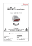
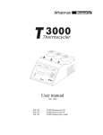
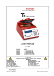
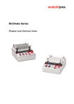
Power Supply Model PS 304 XL Low Voltage Power Supply Instruction Manual 34-9990-114-23 Model PS 304 XL (230 V) PS 304 XL (115 V) Order No. 846-17801017 846-17867304 Please read these instructions carefully before using this apparatus! Biometra GmbH Service Department Rudolf-Wissell-Str. 14 - 16 D-37079 Goettingen Tel.: +49 (0)5 51 50 68 6-10 or -12 Fax.: +49 (0)5 51 50 68 6-11 E-mail: [email protected] Rudolf-Wissell-Str. 30 D-37079 Goettingen Tel: +49 (0)5 51 50 68 6-0 Fax: +49 (0)5 51 50 68 6-66 E-mail: [email protected] Internet: http://www.biometra.de 1 2 This document describes the state at the time of publishing. It needs not necessarily agree with future versions. Subject to change! PS 304 XL Manual, 10_2015 3 1 Contents 1 CONTENTS 3 2 FEATURES 4 3 SPECIFICATIONS 5 4 SAFETY PRECAUTIONS 6 5 FRONT PANEL 8 6 OPERATION 9 6.1 6.2 6.3 6.4 6.5 6.6 UNIT POWER UP AND IMMEDIATE STARTING ADJUSTING OUTPUT SET VALUES WHEN UNIT IS IN STOP MODE ADJUSTING OUTPUT SET VALUES WHEN UNIT IS IN START MODE FURTHER INSTRUCTIONS FAULT AUTOMATIC RESTART 9 9 10 11 12 12 7 TROUBLESHOOTING GUIDE 13 8 CLEANING 14 9 MAINTENANCE 14 10 SERVICE 15 11 EQUIPMENT DECONTAMINATION CERTIFICATE 16 12 NOTE FOR DISPOSAL OF ELECTRIC/ELECTRONIC WASTE 18 13 WARRANTY 19 3 PS 304 XL Manual, 10_2015 4 2 FEATURES Microprocessor controlled switching Power Supply Last settings are automatically restored at power up. The PS 304 XL is equipped with an automatic restart system in case of mains failure. When the power returns, an audible alarm sounds for 10 seconds and the power automatically restarts with the previous set values. If during the power failure the electrophoresis unit is disconnected from the power supply, the alarm still sounds when the mains supply returns. Because no load is connected the power supply will immediately shutdown and set the output to zero. Direct reading of programmed set values and actual values before and during the cycle. Volt and mA adjustable during a cycle. Stabilisation and automatic crossover between the parameters according to the set limitation values and when output limits are reached. 2 Red LED indicate the constant mode. 2 operating modes: constant voltage - constant current. 2 LED Displays for set and output Volt, Current. Settings by tactile switches on moisture resistant membrane panel. Battery-backed memory feature "save" last output set values in the event of a power failure or when the run is terminated and the unit is turned off. 4 recessed safety output jacks allow simultaneous operation of 4 electrophoresis units. Fault detection and 500 µA current leakage detection or no load automatically shuts down output and indicates the fault by STOP LED blinking and audible alarm. PS 304 XL Manual, 10_2015 5 3 Specifications Mains supply voltage fluctuations not to exceed ± 10% of the normal voltage Mains supply, 110 V model : Mains supply, 220 ,V model : Fuse value in the mains plug (UK): Rated input power/current V - range Current - range Power Mode of operation Switching frequency Output regulation stability Minimum output Value display accuracy Mains failure during the run : Fault detection Fault status Earth leakage detection level Output to earth impedance Size Weight Environmental conditions 90 - 130 V; 50 - 60 Hz; T4A fuses 180 - 260 V; 50 - 60 Hz; T2A fuses 3A 150 VA 1 - 300 Volts ; 1 Volt step 1 - 400 mA; 1 mA step 0,6 - 120 Watts Continuous 23 kHz ± 0,2% FS ± ½ digit 1 Volts; 15 µA; 0,6 Watts ± 0,2 FS ± ½ digit Audible alarm and automatic restart with previous set values when mains returns Output supply stop, audible alarm STOP LED blinking Output to earth leakage Output open circuit Output short circuit No regulation (Overheating, power circuit fault) 500 µA 10 M min bypassed by 1 nF max 21 cm x 18 cm x 8 cm ( D x W x H ) 2 kg Indoor use, Altitude up to 2000 m Temperature 10 °C - 40 °C Maximum relative RH 80% for temperature up to 31°C decreasing linearly to 50% RH at 40°C. PS 304 XL Manual, 10_2015 6 4 SAFETY PRECAUTIONS Delicate instument! Handle with care! Danger! High voltage! The power supply is capable of delivering dangerously voltage and has to to be operated by qualified technically trained personnel. Please read the entire users´s manual thoroughly before operating this unit. Take care as the mode of operation is continuous. Make sure that the on/off switch of the Power Supply is always free accessible. The unit must be earthed. Use only the line cords supplied with the unit for safe operation. The use of a line cord other than this supplied by the manufacturer may result in user hazard. For UK users, check the mains plug of the line cord to make sure it is equipped with a protection fuse not exceeding 3 A. Connect the line cord directly into a properly rated, 210/250 VAC 50/60 Hz or 105/125 VAC 50/60 Hz wall outlet. For connection between the power supply and the electrophoresis equipment, use only the safety output leads equipped with black and red recessed plugs. Check the power cords and the black and red recessed safety jacks periodically to make sure that they are in good condition. Do not use cords which are cracked, nicked or in otherwise poor condition. The power supply ust only be connected to electrophoresis equipment manufactured with built-in safety protected male plugs. Always make all connections between the power supply and the electrophoresis equipment prior to start-up of the output. Never place any objects other than high voltage connectors rated to 1000 V into the output jacks. Use electrophoresis equipment that can only be connected when the protection lid is closed. Never attempt to remove the outer casing or make any repair. Contact our Service Department or your distributor if the need for servicing should arise. PS 304 XL Manual, 10_2015 7 If the power supply is used in a manner not specified by the manufacturer then the protection systems of the equipment may be impaired. Never place an electrophoresis instrument on top of the Power Supply! Site the unit such that the rear side has at least 20 cm of clearance to provide for adequate unit ventilation. For additional information, please call your distributor or our Service Department. PS 304 XL Manual, 10_2015 8 5 Front Panel 10 11 1 0 1 0 5 4 1 0 7 2 3 6 1 9 8 1 Tactile switch for the selection of the following modes : - OUT : Display of output values when the unit is running - SET : Display of preset values 2 Tactile switch for selection of parameter to set. Operating in SET mode - Volts : Voltage - mA : Current 3 Current display (mA) 4 Voltage display 5 When blinking, this LED indicates that voltage is in SET mode. When lit, this LED indicates that voltage is the constant parameter during the run. 6 When blinking, this LED indicates that current value is in SET mode. When lit, this LED indicates that current is the constant parameter during the run. 7 Four recessed safety output jacks. 8 Tactile switches for increasing/decreasing Volts and mA. Operating in SET mode. 9 START/STOP switch 10 LED indicating the START status 11 LED indicating the STOP status PS 304 XL Manual, 10_2015 9 6 Operation Remind that last set output values are memorised. 6.1 Unit power up and immediate starting 1. Connect the AC line cord to a grounded, 3-prong wall outlet. 2. Connect the power supply to an electrophoresis device using the power cords supplied. 3. To turn the power supply on, press the main power switch located on the rear panel. The STOP LED (#11) illuminates, and the output LEDs will display zeros. 4. To display and check last set values, depress SET/OUT switch (#1) As soon as this switch is activated, the output LED displays last output set values. 5. If Volts and mA set values are correct, press START/STOP switch (#9) for starting the run. The green LED (#10) illuminates. 6. The actual values are immediately displayed. According settings and gel resistance, one of the constant mode LED will be lit: #5 for constant voltage, #6 for constant current. 7. When separation is complete, press START/STOP (#9) to stop the run. 8. Turn off the power supply by using the main power switch on the rear panel. 6.2 Adjusting output set values when unit is in STOP mode 1. Depress the SET/OUT switch (#1). As soon as this switch is activated, the output LEDs display last output set values. 2. The volts LED (#5) is blinking at first. Increase or decrease voltage by the help of the two SET switches (#8). 3. Depress VOLTS/mA switch (#2) in order to select mA. The mA LED (#6) is blinking. Increase or decrease current by the help of the two SET switches (#8). 4. Press SET/OUT switch (#1)to display the new actual values. Maximum output values are as follow: for 300 Volts - maximum current 400 mA (120 Watts) for 400 mA - maximum voltage 300 Volts (120 Watts) PS 304 XL Manual, 10_2015 10 6.3 Adjusting output set values when unit is in START mode 1. While the unit is running, depress the SET/OUT switch (#1) As soon as one of this switch is activated, the output LEDs display last output set values. 2. The Volts LED (#5) is blinking at first. Increase or decrease voltage by the help of the two SET switches (#8). 3. Depress VOLTS/mA switch (#2) in order to select mA. The mA LED (#6) is blinking. Increase or decrease current by the help of the two SET switches (#8). 4. Press SET/OUT switch (#1) for displaying the new actual values. 5. When separation is terminated, press START/STOP switch (#9) to stop the run. 6. Turn off the power supply by using the main power switch located on the rear panel. PS 304 XL Manual, 10_2015 11 6.4 FURTHER INSTRUCTIONS 1. To view the set values during the run, depress the SET/OUT switch. The Led display the set values as long as this switch is depressed. Once the SET/OUT switch is released, the LED will display the output values for three seconds, and then switch back to displaying the actual output values. 2. It is possible to change the values during the run without depressing the STOP switch. 3. To change the output set values during the run or in STOP status : Depress the SET/OUT switch (#1). As soon as this switch is activated, the output LED display last output set values. The Volts LED (#4) is blinking at first. Increase or decrease voltage by the help of the two SET switches (#8). Depress V/mA switch (#2) in order to select mA. The mA LED (#6) is blinking. Increase or decrease current by the help of the two SET switches (#8). After 3 seconds, the new actual output values are automatically displayed. To read immediately the new actual values, press SET/OUT switch. 4. In START status, when the SET/OUT switch is depressed, the LEDs display the output set values during three seconds and then switch back to displaying the actual output values. 5. To establish the limiting (constant) mode for the particular experiment, set the controlling parameter to the output desired, and increase the other output set value until the appropriate mode LED (Constant voltage or Constant current ) illuminates. 6. If the non-controlling output set values is reached during the course of the run, the power supply will automatically crossover to the new mode and control output relative to that mode. The appropriate mode LED (Constant voltage or Constant current ) will illuminate. 7. If automatic crossover is desired during the run, adjust the output set value of the second controlling parameter to the maximum setting desired. When actual output relative to the second controlling parameter equals its output set value, the output will cross over from the first controlling parameter to the second. 8. When the run has been completed, depress the STOP switch to cease power output. Wait one minute before disconnecting the power cords from the gel unit. 9. Turn the main power switch off when the unit is not in use. PS 304 XL Manual, 10_2015 12 6.5 Fault In a fault situation the unit will shut off power immediately. Simultaneously, the message “Flt” appears on the display, the audible alarm rings and the LED STOP blinks. This automatic cut off indicates one of the following situations: - Output to earth leakage - Output open circuit - Tank’s lead (s) disconnected or defective. - Output short circuit - Overload Press STOP to resume and and to cease the audible alarm. Look for the cause of the fault and correct. Press START to run again. If the unit goes to the fault mode, contact Biometra or your supplier technical service. 6.6 Automatic Restart The power supply will automatically RESTART using the last set values when the power is operating again after a power failure or repetitive micro failures during a cycle. Simultaneously, the message “Str” is displayed and the STOP LED blinks for 10 seconds before operating again. PS 304 XL Manual, 10_2015 13 7 TROUBLESHOOTING GUIDE CONDITION PROBABLE CAUSE REMEDY Display fails to illuminate when the POWER switch is put on. Fuses have blown See Warning below The desired MODE is not flashing. One of the other parameters is limiting output. Increase the output value of the limiting parameter until the desired output mode is controlling. Two different modes are blinking alternatively. Settings for both parameters are too close to the actual output. Increase the set value for the mode you do not wish to be limiting. Settings switches are not working. SET mode is not operating. Depress SET switch Audible alarm at power up. Automatic restart is coming. Press STOP to stop this function. The unit has been previously cut off by the power switch when running. Unit must always be stopped by the STOP switch prior to cut off by the power switch. Impossible to start the run, Unit is coming back on STOP mode with audible Alarm A fault situation avoid the START mode to operate. Check the cause of the fault and Rectify (see section 6.5) Message “Str” is displayed. See automatic restart paragraph, section 6.6. WARNING Never attempt to remove the outer casing or make any unit repairs. Contact your distributor if the need for repair or servicing should arise Should the power supply fail, DO NOT remove the outer case of the unit and attempt any repairs. Contact your distributor if the need for servicing the unit should arise. PS 304 XL Manual, 10_2015 14 8 CLEANING The power supply may be cleaned as required when the main supply is isolated. Cleaning should be carried out with a cloth moistened with water or with tissues impregnated with 70% Iso-propyl alcohol. No other cleaning solutions should be used. 9 MAINTENANCE There are no internal operator serviceable parts in this power supply. If the power should fail, the unit must be returned to the authorised Service centre. See “Instructions for return shipment”, section 10. PS 304 XL Manual, 10_2015 15 10 Service Should you have any problems with this unit, please contact our service department or your local Biometra dealer: Biometra GmbH Service Department Rudolf-Wissell-Straße 14 - 16 D-37079 Goettingen Phone: +49 (0)5 51 50 68 6 - 10 or 12 Fax: +49 (0)5 51 50 68 6 -11 e-mail: [email protected] If you would like to send the unit back to us, please read the following return instructions. Instructions for return shipment Return only defective devices. For technical problems which are not definitively recognisable as device faults please contact the Technical Service Department at Biometra (Tel.: +49 (0)5 51-50 88 110 or -12, Fax: +49 (0)5 51-50 88 1-11, e-mail: [email protected]). Please contact our service department for providing a return authorization number (RAN). This number has to be applied clearly visible to the outer box. Returns without the RAN will be not be accepted! Important: Carefully clean all parts of the instrument from residues, and of biologically dangerous, chemical or radioactive contaminants. If an instrument is contaminated, Biometra will be forced to refuse to accept the device. The sender of the repair order will be held liable for possible damages and losses resulting from insufficient decontamination of the device. Please prepare written confirmation (use the “Equipment Decontamination Declaration” following on the next page) that the device is free of biologically dangerous, chemical or radioactive contaminants. This confirmation must be attached to the outside of the packaging. Use the original packing or a similarly robust packing when returning the device. If not available, contact Biometra or your local distributor. Label the outside of the box with “CAUTION! SENSITIVE INSTRUMENT!” and the RAN number sticker. Attach the Decontamination Declarartion! Please enclose a note which contains the following: a) Sender’s name and address, b) Name of a contact person for further inquiries with telephone number. c) Precise description of the fault, which also reveals during which procedures the fault occurred, if possible. PS 304 XL Manual, 10_2015 16 11 Equipment Decontamination Certificate To enable us to comply with german law (i.e. §71 StrlSchV, §17 GefStoffV and §19 ChemG) and to avoid exposure to hazardous materials during handling or repair, please complete this form, prior to the equipment leaving your laboratory. COMPANY / INSTITUTE _____________________________________________________ ADDRESS __________________________________________________________________ PHONE NO _________________________ E-MAIL __________________________________________________________________ EQUIPMENT If on loan / evaluation FAX NO___________________________ Model ______________ Serial No ______________ ______________ ______________ ______________ ______________ ______________ ______________ Start Date: __________________ Finish Date __________________ Hazardous materials used with this equipment: __________________________________________________________________________ __________________________________________________________________________ __________________________________________________________________________ Method of cleaning / decontamination: __________________________________________________________________________ __________________________________________________________________________ __________________________________________________________________________ The equipment has been cleaned and decontaminated: NAME __________________________________ (HEAD OF DIV./ DEP./ INSTITUTE / COMPANY) POSITION ________________________ SIGNED ________________________________ DATE ____________________________ PLEASE RETURN THIS FORM TO BIOMETRA GMBH OR YOUR LOCAL BIOMETRA DISTRIBUTOR TOGETHER WITH THE EQUIPMENT. PLEASE ATTACH THIS CERTIFICATE OUTSIDE THE PACKAGING. INSTRUMENTS WITHOUT THIS CERTIFICATE ATTACHED WILL BE RETURNED TO SENDER. PS 304 XL Manual, 10_2015 17 General Information for Decontamination: Please contact your responsible health & safety officer for details. Use of radioactive substances: Please contact your responsible person for details. Use of genetically change organism or parts of those: Please contact your responsible person for details. PS 304 XL Manual, 10_2015 18 12 Note for Disposal of Electric/Electronic Waste This symbol (the crossed-out wheelie bin) means, that this product should be brought to the return systems and/or separate systems available to end-users according to yours country regulations, when this product has reached the end of its lifetime! For details, please contact your local distributor! This symbol applies only to the countries within the EEA*. *EEA = European Economics Area, comprising all EU-members plus Norway, Iceland and Liechtenstein. PS 304 XL Manual, 10_2015 19 13 Warranty This laboratory instrument is produced with the highest practical standards of materials, workmanship, and design. The design and manufacture of parts have been conceived with one purpose - to produce units which will give satisfactory service. Biometra GmbH guarantees this unit to be free from defects in materials or workmanship under normal use or service for 24 month from date of shipment. If, during this time, this unit proves defective in materials or workmanship, Biometra GmbH will repair or replace it free of charge if returned to us prepaid. This guarantee does not cover damage in transit, damage caused by carelessness, misuse or neglect, or unsatisfactory performance as a result of conditions beyond our control; or consequential losses as a result of failure of our product. Biometra GmbH Rudolf-Wissell-Str. 30 D-37079 Goettingen Tel: +49 (0)5 51 50 68 6-0 Fax: +49 (0)5 51 50 68 6-66 e-mail: [email protected] internet: http://www.biometra.com Service Department Rudolf-Wissell-Str. 14 - 16 D-37079 Goettingen Tel.: +49 (0)5 51 50 68 6-10 or -12 Fax.: +49 (0)5 51 50 68 8-11 e-mail: [email protected] PS 304 XL Manual, 10_2015