1
TAW-270NH2A
The sales agent should inform customers
regarding the correct method of installation.
Please pass installation manual to customer
together with operation manual, and request
customer to keep them after installation.
OUTDOOR UNIT
RAW-25NH2A
Refrigerant: R410A (GWP 2000)
Do not set it up the place where rain water splashes. The electric
shock and a fire might occur.
Do not install at a location where there is flammable gas, steam,
oil and smoke.
Place the tank unit and its connecting cord at least 1m away form
the antenna or signal line of television, radio or telephone.
This is to avoid noise interference.
Do not set it up in the place where water in piping and in the
tank freeze.
It is necessary to set it up in the place where the waterproof and
waste water treatment were done so that there is no obstacle
when the water leaks by any chance.
The water may drip form the discharge pipe of the pressure-relief
valve and that this pipe must be left open to the atmosphere.
Discharge pipe connected to the pressure-relief valve is to be
installed in a continuously downward direction and in a frost-free
environment.
It is necessary to have space for the maintenance work and set
it up. The space necessary for the maintenance work is specified
in the following figures.
Vertically set it up. Moreover, do not overset it.
Do not set it up in humid place like the bathroom etc.
Do not set it up near the septic tank.
Read the safety precautions carefully before operating the unit.
The contents of this section are vital to ensure safety. Please pay special attention to the following sign.
! WARNING ........ Incorrect methods of installation may cause death or serious injury.
! CAUTION ......... Improper installation may result in serious consequence.
Be sure that the unit operates in proper condition after installation. Explain to customer the proper way of
operating the unit as described in the operation manual.
WARNING
!
%, +*.,- 2(.+ ,%, '- (+ *.%" -!'""' -( "',-%% 2(.+ .'"- -+ %$ ,!(+- "+."- (+ +
&2 (.+ " 2(. ( -! "',-%%-"(' 0(+$ 2(.+,%
%, (,+/ -! "',-+.-"(' ,-- "' -! "',-%%-"(' &'.% .+"' -! )+(,, ( "',-%%-"(' &)+()+
"',-%%-"(' &2 ., 0-+ %$ %-+"% ,!($ ' +
$ ,.+ -!- -! .'"- ", &(.'- - %(-"(' 0!"! ", % -( )+(/" .%% ,.))(+- (+ -! 0" !- ( -! .'"-
'(- -! .'"- &2 (%%), ' "&)(, ' +
,+/ -! +.%, ' + .%-"(', ( -! %-+"% "',-%%-"(' ' -! &-!(, ,+" "' -! "',-%%-"('
&'.% 0!' %"' 0"-! -! %-+"% 0(+$ , )(0+ %, ))+(/ 2 -! .-!(+"-", ( 2(.+ (.'-+2
,.+-(.,-!,)"0"+,(+(''-"' -!-'$'(.-((+.'"-,%,',.+-!--!(''-"(',
+ -" !- -+ -! ('.-(+, ( -! 0"+, + "',+- "'-( -! -+&"'%, &)+()+ "',+-"(' ' %((, ('--
&2 ., (/+!-"' ' +
WARNING
The outdoor unit must be mounted at a location which can support
heavy weight. Otherwise, noise and vibration will increase.
It is recommended to install the unit at the place not under
direct sunshine or rain, and with good ventilation, in order
to keep the performance.
In order to protect animals or plants, please prevent to
blow to them directly.
The clearances of the unit from top, left, right and front
are specified in figure below. At least three of the above
sides must be open air.
Be sure that the hot air blown out of the unit and noise
do not disturb the neighbourhood.
Do not install at a location where there is flammable gas,
steam, oil and smoke.
The location must be convenient for water drainage.
Place the outdoor unit and its connecting cord at least 1m
away from the antenna or signal line of television, radio
or telephone. This is to avoid noise interference.
CAUTION
!
SAFETY PRECAUTION
!
Must be placed at location that can withstand the weight
of its full capacity.
!
OUTDOOR UNIT
TANK UNIT
Carefully read through the procedures of
proper installation before starting installation
work.
WARNING
!
CAUTION
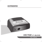
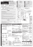
Figure showing the Installation
of Tank and Outdoor Unit.
Names of Outdoor Components
No.
Item
Qty
Dimension to mount
Sealing material
600
1
1
Bush
2
2
(unit: mm)
730
(Please note the following matters and obtain permission from customer before installation).
TANK UNIT
FOR SERVICE PERSONNEL ONLY
Drain Pipe
1
3
%,.,-!,)"(&)(''-,(+"',-%%-"('0(+$-!+0",-!.'"-,&2(%%),(+0-+%$ %-+" ,!($ ' + &2 (.+
,.+ -( ., -! ,)" )")"' ,- (+ -!+0", -!", &2 +,.%- "' +($' ())+ )"), (+
.%-,
!' "',-%%"' (+ +&(/"' -! ,'"-+2 !(- 0-+ !- ).&) ('%2 ,)" ++" +'- ,!%% %%(0('(-%%(0"+(+&(",-.+-(+&"'"'-!++" +-"('2%-!+0",)+,,.+"'-!++" +-"('
2% &2 (& '(+&%%2 !" ! ,( -!- +.)-.+ &2 .,
-+ (&)%-"(' ( "',-%%-"(' 0(+$ &$ ,.+ -!- -!+ ", '( ++" +'- , %$, "'-( -! +((& 1)(, -(
-! + "' -! '+"/' !-+ ,) !-+ - )(",(' , &2 (.+
'.-!(+"3 &("-"(', -( -! ,'"-+2 !(- 0-+ !- ).&) &2 ' +(., +$(0' (.+,
)%, %% *.%" ,'"-+2 !(- 0-+ !- ).&) -!'""' (+ %-+""' &)+()+ +)"+, &2 +,.%- "'
0-+ %$ %-+" ,!($ ' + -
,.+ -( ., -! ,.))%" (+ ,)" "',-%%-"(' )+-, , ( (-!+ )+-, &2 ., -! .'"- -( /"+-
%((,%2 ' &2 ., 0-+ %$ %-+"% ,!($ (+ +
%-+"%0(+$&.,-++"(.-"'(+'0"-!-!"',-%%-"('&'.%'-!'-"('%%-+"%0"+"' +.%, (+ ( ( )+-" ',."'- )"-2 (+ "'(&)%- %-+"% 0(+$ &2 ., %-+"% ,!($ (+
+
,.+ -( ., "- )(0+ "+."- /+ ., )(0+ "+."- ,!+ 0"-! '(-!+ ))%"'
(+ 0"+"' ., % %(' '(. ! -( (/+ -! '-"+ ",-' 0"-! '( (''-"('
( '(- ).- (-!+ %(, (' -! )(0+ ,.))%2 ., "- )(0+ "+."-
"%.+ -( ( ,( &2 ., '(+&% !- %-+"% ,!($ (+ +
, -! ,)" -2), ( 0"+, (+ %-+"% (''-"(', -0' -! -'$ ' (.-((+ .'"-
"+&%2 %&) -! "'-+(''-"' 0"+, ,( -!- -!"+ -+&"'%, +"/ '( 1-+'% ,-+,,
'(&)%- (''-"(', (+ %&)"' &2 ., -+&"'% (/+!-"' (+ +
-+ (''-"' -! "'-+(''-"' ' ,.))%2 0"+"' ,.+ -( ,!) -! %, ,( -!- -!2 ( '(- ).-
.'. (+ (' -! %-+"% (/+, (+ )'%,
',-%% (/+, (/+ -! 0"+, '(&)%- (/+ "',-%%-"(' &2 ., -+&"'% (/+!-"' %-+"% ,!($ (+
+
'2 ++" +'- !, %$ (.- .+"' -! "',-%%-"(' 0(+$ /'-"%- -! +((&
! ++" +'- )+(., )(",('(., , " 1)(, -( &,
-+ %% "',-%%-"(' ", (&)%- !$ ' &$ ,.+ -!- '( ++" +'- ", %$"' !- ++" +'- )+(. )(",('(., , " 1)(, -( &,
.+"' ).&)(0' ()+-"(' ,-() -! (&)+,,(+ (+ +&(/"' -! ++" +'- )")"' -! (&)+,,(+ ", ,-"%% +.''"' ' ,+/" /%/ "' ()' .+"' ).&)(0' "+ 0"%% ,.$ "' 0!' -!
++" +'- )")"' ", +&(/ .,"' '(+&% )+,,.+ -! ++" +'- 2% 0!"! 0"%% % -( +$ '
/' -( "'#.+2
.+"' "',-%%-"(' --! -! ++" +-"' )")"' ,.+%2 (+ +.''"' -! (&)+,,(+
-! (&)+,,(+ ", '(- --! ' -! ,+/" /%/ ", ()' .+"' ).&)(0' "+ 0"%% ,.$ "' 0!'
-! (&)+,,(+ ", +.''"' .,"' '(+&% )+,,.+ "' -! ++" +-"(' 2% 0!"! 0"%% % -( +$ ' /' -( "'#.+2
,.+ -( ,-%",! ' +-! ( '(- +-! -! .'"- -( .-"%"-2 )") ,.+ ,(++ (+ -%)!(' +-!
'(&)%-+-!&2.,%-+"%,!($!" !,.+ .++'-(+&%" !-"' (+,(.+,&2.,& -( -! (.-((+ .'"-
,.+ -( "',-%% ' +-! %$ "+."- +$+ "%.+ -( ( ,( &2 ., %-+"% ,!($
)+,,.++%" /%/ ,!(.% "',-%%
"-!(.- )+,,.++%" /%/ -! -'$ &2 +($'
!
"+."- +$+ (+ -"& %2 ., ' %$ .++'- +$+ &.,- "',-%% "-!(.- -!& -!
' + ( %-+" ,!($ 1",-,
&"' ,0"-! 0"-! ('-- ) ( &(+ -!' && !, -( "',-%% "' -! )(0+ ,.))%2 %"'
%, ',.+ ,&((-! (0 ( 0-+ 0!' "',-%%"' -! +"' !(,
")"' ,!%% ,."-% ,.))(+- 0"-! &1"&.& ,)"' ( & -0' -! ,.))(+-,
%, ',.+ -! ((+ 0!+ -! .'"- ", "',-%% (+ 0-+)+(( ' +"' -!+0", "- &2 & (0',-"+,
4
1
Dimension of Mounting Stand
of the Outdoor unit
! -'$ ,!(.% 1 ,-%2 - -! %(-"(' 0!"! ' ,.))(+- !/2 0" !-
-!+0", "- &2 %% 2 +-!*.$ ' ,( (' ' ., "'#.+2
PRESSURE-RELIEF VALVE
Pressure-relief valve must use the following one.
The tank has to mounted with a pressure-relief, diameter 3/4” following standard FN36, 40.
(But this may be suitable for France only)
The pressure-relief valve is installed in the water supply line
Between the cold water inlet and pressure-relief valve, you should not install water check valves.
Pressure relief valve can prevent excess water pressure which cause volumetric expansion of heated water.
Pressure relief valve discharges up to 3% of the capacity of the equipment in the process of boiling the water.
PRESSURE REDUCING VALVE
Please install the pressure reducing valve in the water supply line as much as possible when the tap water pressure
becomes 3.5bar or more.
MIXER TAP
Please install thermostat type mixer tap in each hot-water supply spot to prevent the scald accident.
PLUMBING
Please set up the drain trap in the drainage piping.
The drainage gas flows backward if there is no drain trap, the sanitary hot water pump corrodes remarkably, and it breaks
down.
Please connect it through a dielectric joint to prevent the electrolysis phenomenon.
Please make piping parts around the tank such as pressure-relief valve and the drain valve to be easily maintenanced
and checked.
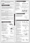
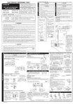
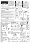
Hot water outlet
(G 3/4”B)
! WARNING
A pressure-relief valve should be installed.
Without a pressure-relief valve, the tank may
be broken.
Inner cover
Please remove outer and inner cover when
connecting the piping and connecting cord.
Mg-Anode
Outer cover
Cold water inlet (G3/4”)
Refrigerating pipe
(1/4” and 3/8”)
Figure showing the Installation of water piping
Mixer tap
Hot water supply line
Tank unit
Purge valve
Hot water outlet
Drainpipe
Pressure reducing valve
Water check valve
Cold water supply line
Cold water inlet
Water valve
Pressure-relief valve
Drain valve
Hopper
<IA805: A >
The difference in height between
the tank and outdoor unit should
be kept max 10m.
The refrigerating pipe, should
all be insulated with insulation
pipe and then wrapped with
vinyl tape. (The insulator will be
deteriorated if it is not wrapped
with tape).
WATER QUALITY
Water that conforms to the drinking water regulation in each country must be used. Do not use water that is contains
impurities such as salinity, lime, etc. Like well-water.
Please install the water softener device when the hardness of water is high. (Maximum hardness French degree 25°F)
CAUTION
( '(- "',-%% -! .'"- '+ %(-"(' 0!+ -!+ ", &&% , ! (.-((+ .'"- &2 -!
+ " &&% , %$, +(.' "-
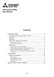
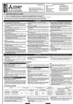
Bush
Drainpipe
Please face this side (suction
side) of the unit to the wall.
Please remove side cover
when connecting the piping
and connecting cord.
OUTDOOR UNIT
Pull downward
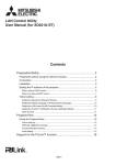
CONDENSED WATER DISPOSAL OF OUTDOOR UNIT
There are holes on the base of outdoor unit for condensed
water to exhaust.
In order to flow condensed water to the drain, the unit is installed on a
stand or a block so that the unit is 100mm above the ground as shown
figure. Join the drain pipe to one hole.
At first insert one portion of the hook to the base (Portion A), then pull the
drain pipe in the direction shown by the arrow while inserting the hook
into the base. After installation, check whether the drain pipe cling to the
base firmly.
A
BASE
DRAIN PIPE
When the air conditioner is used in low temperature
and in snowy conditions, water from the heat
exchanger may freeze on the base surface to cause
poor drainage. When using the sanitary hot water
heat pump in such areas, do not install the bush.
Keep a space of at least 300mm between the drain
hole and the supposed snow height. When using
the drain pipe, consult your sales agent.
This sanitary hot water heat pump can be connected either A or B power supply
method according to electricity supply contract. But how to set the switch is different
in A or B.
A: Full time power supply
B: Off peak hours power supply
Procedures of Wiring
In
!
Jagged edge will cause leakage.
Point the side to be trimmed downwards during trimming to prevent copper
chips from entering the pipe.
Before flaring, please put
on the flare nut.
Outer
Diameter (mm)
2
9.52
0.0
~
~
0.5mm
0.5mm
Connecting Cord
Control line
In case of removing flare nut of an Indoor unit, first remove a
nut of small diameter side, or a seal cap of big diameter side will
fly out due to high pressure gas inside tank. Prevent water from
entering into the piping when working.
Torque N·m
(kgf · cm)
Small dia. side
6.35 (1/4")
13.7 – 18.6 (140 – 190)
Large dia. side
9.52 (3/8")
34.3 – 44.1 (350 – 450)
Small dia. side
Valve
head cap Large dia. side
6.35 (1/4")
19.6 – 24.5 (200 ~ 250)
9.52 (3/8")
19.6 – 24.5 (200 ~ 250)
Cable length
Wire cross-section
up to 16m
up to 15m
up to 25m
1.6mm2
2.5mm2
2.5mm2
!
Use 16A
breaker
Please fix the connecting cord in the
band.
If it is not fixed, external force apply to
joint, it causes heat and a fire, etc.
The connecting cord should not touch
to pipes.
(It becomes high temperature.) Please
install outer and inner cover surely
after constructs it.
Earth
terminal
This switch must be set before turning on the electric power.
Incorrect connection of the A, B terminals of the tank unit and the C, D terminals
of the outdoor unit will damage the electrical parts of the outdoor unit.
The space with the
penetration part of the
cover is buried.
Tank Unit
25mm
10mm
Control line
Once turning on the electric power, the setting cannot be changed for a few minutes
or for a few hours after turning off the power, until the electricity charged in the
electric parts is discharged.
In case that it is necessary to change the setting of the switch after turning on the
electric power, please follow the procedure below.
GRN + YEL
25mm
10mm
10mm
10mm
35mm
Strip wires
Outdoor Unit
Power line
Control line
Strip wires
25mm
10mm
Please fill the tank full first before operation.
The operation without full water in the tank might cause overheat of the unit
and causes damage.
1. Fills the tank with water.
1
Turn on water tap close drain valve.
2
Turn on all connected mixer tap (hot water side). It take about 20 to 30
minutes to fill up the tank. Please keep all taps open for a while in order
to clean the tank and the drain pipes by running water.
3
Close all connected mixer taps (hot water side) and open all taps (cold
water side). Let the cold water run for a while to clean out the tank.
4
Turn off all connected mixer taps.
5
Inspection
After filling the tank, check all pipe joints and the tank for leakage.
Check operation of pressure-relief valve.
2. Turn on the circuit breaker.
In case that the electric power is supplied to both of tank unit and outdoor
unit, please always turn on the outdoor unit side first.
If the tank side is turned on first, it may fall into error mode of “E0 03” and
the unit is unable to operate.
When once the tank side is turned on first and it falls in to error mode of
“E0 03” by mistake, please turn on the outdoor first, then turn on the tank
side, after following measures.
(1) Turn off the electric power.
(2) Get off outer cover and inner cover from the control box.
(3) Pull out the connector CN71 from PWB assembly.
(4) Wait more than ten seconds
(6) Attach inner cover and outer cover of the control box
If error mode does not disappear after the procedure above, the machine
is broken.
! CAUTION
Check the operation of leak current breaker. There is fear of an electric shock.
Wiring of The Outdoor Unit
35mm
Strip wires
! WARNING
The naked part of the wire core should be 10 mm and fix it to the terminal
tightly. Then try to pull the individual wire to check if the contact is tight.
Improper insertion may burn the terminal.
Be sure to use only power cables approved from the authorities in your country.
For example in Germany: Cable type: NYM 3x1.5mm2.
Please refer to the installation manual for wire connection to the terminals of
the units. The cabling must meet the standards of electrical installation.
There is a AC voltage of 230V between the L and N terminals. Therefore,
before servicing, be sure to switch off the main switch.
3. Make test run.
Please remove the side cover for wire connection.
10mm
<IA805: A >
Please connect to off peak hours power supply after connecting to live power
and testing.
25mm
10mm
GRN + YEL
Please ensure that the sanitary hot water heat pump is in normal operating
condition during the operation test.
(5) Reconnect the connector CN71.
The method to change the setting after turning on the electric power.
(1) Turn off the electric power.
(2) Get off outer cover and inner cover from the control box.
(3) Pull out the connector CN71 from PWB assembly.
(4) Wait more than ten seconds
(5) Change the setting of the switch.
(6) Reconnect the connector CN71.
(7) Attach inner cover and outer cover of the control box.
Operation Test
! CAUTION
Please refer to the Installation Manual when connecting the wires for the tank
unit and the outdoor unit.
Power line
2
! CAUTION
Strip wires
When pumping starts, slightly loosen the
flare nut to check of air sucked in. Then
tighten the flare nut.
L N A B C D
Power line
of terminal
Vacuum pump
adapter
Please tie the pipe and connecting cord together with vinyl tape as shown
in the figure showing the installation of tank and outdoor unit. Then fix their
position with holders.
To enhance the heat insulation and to prevent water condensation, please cover
the outdoor part of the refrigerating pipe with insulation material.
Completely seal any gap with putty.
Connecting Cord
Processing
Vacuum
pump
Please remove outer and inner cover for wire connection.
Outdoor Unit
Power line
Valve
"$# # #
1
Wiring of The Tank Unit
WARNING
Line Cord
Manifold valve
Charge hose
12.3 – 15.7 (125 ~ 160)
Investigate the power supply capacity and other electrical conditions at the installation
location.
Depending on the model of room air conditioner to be installed, request the customer
to make arrangements for the necessary electrical work etc.
The electrical work includes the wiring work up the outdoor. In localities where electrical
conditions are poor, use of a voltage regulation is recommended.
Line Cord
Closed
R410A
If gas leakage occurs, further tighten the connection to
stop leakage. (Use the detector provided for R410A)
Before installation, the power source must be checked and necessary wiring work
must be completed. To make the wiring capacity proper, use the wire gauges list
below for the lead-in from a pole transformer and for the wiring from a switch board
of fuse box to the main switch and tank unit and outdoor unit in consideration of the
locked rotor current.
case that power is supplied to Tank and Outdoor unit
Control line
4
Remove the charge hose and tighten
the cap of valve head. Check the cap’s
periphery if there is any gas leakage.
The task is then completed.
Valve
Hi
Please use gas leakage detector to check if leakage
occurs at the connection of Flare nut as shown on
the right.
Checking for the electric source and the voltage range
Tank Unit
3
Completely unscrew the spindle of
the service valve (at 2 places) in anticlockwise direction to allow the flow
of coolant (using Hexagonal Wrench
key).
Lo
Gas Leakage Inspection
CONNECTION OF POWER CORD
0.0
Outer
dia.of pipe
Use 16A
breaker
In
6.35
2
Meter showing pressure
Please be careful when bending the copper pipe.
Applied frozen grease to the connection points and then screw in manually. After that,
use a torque wrench to tighten the connection. Problem may arise if overtightened
when connecting the pipe.
Outdoor Unit
Power line
A (mm)
For R410A tool
Fully tighten the “Hi” shuttle of the
manifold valve and completely unscrew
the “Lo” shuttle. Run the vacuum
pump for about 10–15 minutes, then
completely tighten the “Lo” shuttle and
switch off the vacuum pump.
When the meter reaches - 101KPa
(-76cmHg) during pumping, fully
tighten the shuttle.
Pipe Connection
! CAUTION
CAUTION
IMPORTANT
Tank Unit
As shown in right figure, remove the
cap of valve core. Then, connect
the charge hose. Remove the cap
of valve head. Connect the vacuum
pump adapter to the vacuum pump
and connect the charge hose to the
adapter.
1
case that power is supplied to Tank Unit
Line Cord
!$!"$"$$$ !!%
Valve core cap
THIS APPLIANCE MUST BE EARTHED.
Removal Of Air From The Pipe And Gas Leakage Inspection
Use a pipe cutter to cut the copper pipe.
For more details, refer to the installation manual for cold areas.
! WARNING
3
Preparation of Pipe
AIR REMOVAL
1
FINAL STAGE OF INSTALLATION
Please mount the Outdoor unit on stable ground to prevent vibration
and increase of noise level.
Decide the location for piping after sorting out the different types of
pipe available.
When removing side cover, please pull the handle after undoing the
hook by pulling it downward.
INSTALLATION OF REFRIGERATING PIPES AND AIR REMOVAL
!
WARNING
If you cannot attach the side
cover due to the connecting
cord, press the connecting cord
in direction to the front panel to
fix it.
Be sure that the hooks of the
side cover is fixed in certainly.
Otherwise water leakage may
occur and this causes short
circuit or faults.
The connecting cord should not
touch to service valve and pipes.
(It becomes high temperature.)
Please fix the connecting cord
in the band.
If it is not fixed, external force
apply to joint, it causes heat and
a fire, etc.
4. Reconfirm whether the water leak is found form the joint of piping and the
tank. Moreover, confirm the operation of the pressure-relief valve.
L N C D
Use 16A Time
Delay Fuse
! CAUTION
Earth terminal
Please ensure that the pressure-relief valve work.
If you continue to use malfunction pressure-relief valve, it may break the tank
or water may leak from the valve.
5. Explain to your customer the proper operation procedures as described in
the user’s manual.