1
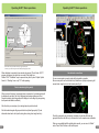
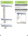
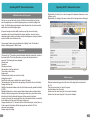
SHOOTER TRAINING SYSTEMS
SCATT WM9 / WS1 / USB
USER MANUAL
SCATT company
Tel: +7 (499) 710-06-67
e-mail: [email protected]
www.scatt.com
SCATT company all rights reserved.
Please read this manual to its end
to secure safety and best quality
of the system’s operation.
Content
Advanced functions
Basic operations
Dear Customer, thank you for buying this system. Please read this manual to its end
to secure safety and best quality of the system’s operation.
Supplied accessories
Software installation
Electronic target installation
Optical sensor OS-02 / WS-3 installation
Optical sensor WS-M01 installation
Starting SCATT
Printing paper target
New practice starting
Optical sensor calibration
Practice window (sighting mode)
Use electronic corrections
Scaling the target
Practice window (match mode)
Control panel
Saving training results
Opening saved result
Additional features of the program
General info
Distance curve
Coordination curve
Shift curve
Aiming point speed curve
Time intervals graph
Probability graph
Compare two training
Options menu
Shots parameters menu
Short keys
Troubleshooting
Service
Specifications
Template for mounting electronic target on the wall
4
7
8
9
11
13
13
14
15
16
17
18
18
19
21
21
22
22
23
24
25
26
27
38
30
31
32
32
33
33
33
35
3
SCATT WS1 accessories
SCATT WM9 accessories
Please check and identify all supplied accessories
Please check and identify all supplied accsessories
1
1. Electronic target WT-01
1. Electronic target WT-01
2. Electronic target control unit WTC-01
2. Electronic target control unit WTC-01
3. Optical sensor WS-M01
3. Optical sensor WS-03
1
4. Software CD
5. Software CD
5. User guide
2
4. Mounting parts set
6. User guide
6. Electronic target control unit interface cable
2
7. Electronic target control unit interface cable
7. Electronic target interface cable
8. Electronic target interface cable
3
3
9. Optical sensor charging cable
4
er
Us
a
nu
ma
l
4
5
5
al
nu
ma
er
Us
6
6
7
7
8
9
4
5
SCATT USB accessories
System installation
Please check and identify all supplied accessories
1. Electronic target ST4-12
2. Electronic target control unit WTC-01
Software installation
Before using SCATT system, you need to install SCATT drivers and software.
3. Optical sensor OS-02
1
4. Mounting parts set
5. Software CD
2
Insert disk (provided in a set) in the CD-ROM drive, select SCATT. EXE icon in the
disc drive window and follow instructions on the screen (fig. 1).
Install drivers before attaching SCATT devices to the computer, then attach all
devices one by one.
6. User guide
7. Electronic target control unit interface cable
8. Electronic target interface cable
3
9. Optical sensor interface cable
4
5
er
Us
al
nu
ma
Fig. 1
6
While all necessary software is included on CD, we recommend to download latest
versions of software from http://www.scatt.com.
7
8
9
6
7
System installation
Optical sensor OS-02 / WS-03 installation
OS-02 optical sensor connection
Electronic target installation
Install electronic target on a tripod (photo tripod) or fix it on the wall at the distance
from 3 to 6 meters for SCATT WM9 model and from 4 to 10 meters for SCATT WS1
and SCATT USB models so that the LEDs face the shooter. Insert a paper target,
but make sure it doesn’t cover the LEDs. Connect electronic target to USB port of
your computer as shown on a scheme.
Connect optical sensor model OS-02 to USB port of your computer by standard USB
A - mini B type cable (included with your kit).
1
Infrared LEDs
1 - OS-02 optical sensor
2 - USB A - mini B cable
3 - USB connector
3
Paper
target
Wall-attaching holes
2
Paper
target
fixators
WS-03 optical sensor connection
Infrared receiver
(WT-01 model only)
Electronic target WT-01
Multicolor LEDs
Optical sensor has a two-way infrared connection with the electronic target. Sensor
has a built-in battery and can be recharged from USB port of your computer. Full
charging cycle is1.5 hours. Operating time of a fully charged battery approximately 30
hours of non-stop aiming or 10.000 shots (with an average time 10 sec. Per shot).
In case of non-use, the sensor automatically switches to sleep mode.
1
Target number
switcher*
3
4
*(used only when more
than one target
connected)
Extra electronic target
connector
1 - WS-03 optical sensor
2 - USB A - mini B cable (for charging)
3 - LED charging indicator
4 - USB connector
2
SCATT trigger sensor (not included in the set) can be plugged into the USB
connector of WS-03 optical sensor.
Nut for photo
tripod fixation
Clamp position adjusting
You can change clamp position on optical sensor body.
Electronic target control unit
WTC-01
1 - Optical sensor body
2 - Clamp
3 - Clamp fixing screw
Connect to USB port of your PC
8
PC
1
3
2
9
Optical sensor OS-02 / WS-03 installation
Optical sensor WS-M01 installation
Installation sensor on the barrel
Installation sensor into the 9 mm barrel
• Insert the optical sensor into a 9mm
barrel
(The barrel must be clean and dry).
3
Installation options:
2
• Mounting the optical sensor on the
barrel or gas cylinders using the
mounting prism and plate with screw
4
• Mounting the optical sensor on short
barrel pistols using barrel inserts of
various calibers
7
4
2
3
1
1. Optical sensor WS-M01
2. Battery cover (Tighten firmly)
3. Battery (1.5V – SW393SR)
4. Rubber O-ring
1
Optical sensor has a two-way infrared connection with the electronic target.
Operating time from one battery (1.5V – SW 393 SR) about 10,000 shots (with
an average time of sighting 3sec)*.
In case of prolonged non-use, the sensor automatically switches to sleeping mode.
Warning!
Observe the battery polarity. To avoid battery discharge, store sensor away from
strong lights or direct sunlight. With long-term (more than a week) non-use the
sensor, please remove the battery.
7
1 - Optical sensor
2 - Mounting prism
3 - Mounting plate with screw
4 - Barrel of a gun
5 - Barrel insert (not included in a set)
6 - Short barrel pistol
Before using the sensor, make sure the firearm is not loaded!
Don’t forget remove the sensor from barrel after training.
*To achieve the stated performance, we recommend using battery of the following
manufacturers: RENATA, DURACELL, ENERGIZER, VARTA, GP.
We do not recommend the use of zinc-air batteries are labeled "PR".
10
11
Operating SCATT / Basic operations
Optical sensor WS-M01 installation
Starting SCATT
Installation sensor on the barrel
For fixation of the optical sensor outside the barrel extra mounting parts are required
(not included with your kit).
Installation options:
When hardware and software installation is over, select SCATT icon in a program
manager to start the program (fig. 2).
• Optical sensor fix on barrel (or gas
cylinder) using mounting prism
and plate with screw.
4
• Optical sensor fix on barrel using
barrel inserts of various calibers.
3
5
1. Optical sensor WS-M01
2. Clamp S9
3. Mounting prism
4. Mounting plate with screw
5. Barrel
6. Fixing screw
6
2
1
Optical sensor capture area
To achieve the best results, use an
optical sensor within the work area.
Fig. 2
Printing paper target
1. Electronic target
2. Optical sensor
Before starting a new training, you need to print out a paper target, corresponding
to the desired distance, and exercise (program allows you simulate shooting at
distances up to 1000 meters).
To print a custom paper target, connect printer to your computer and select
“Print target” option in “Tools” menu of the SCATT program control panel (fig. 3).
4
1
0
1
*
m
o
7.
Fig. 3
5
2
o
* Distances for optical sensor
models OS-02 and WS-03
12
5
7.
13
Operating SCATT / Basic operations
Operating SCATT / Basic operations
In this window (fig. 4) you need to select the exercise (target and simulated distance)
and enter the distance to electronic target and then click "Print" button.
The printed target will correspond in scale with the distance to simulated target.
Shooter Name
Cut and paste it into paper target fixators of the electronic target as shown on a
scheme (see electronic target installation).
Shooting exercise
Target preview
Shooter exercises
Fig. 5
Optical sensor calibration
After you clicked on "Start" button, SCATT calibration window will open. In this
window (fig. 6) you need to calibrate the optical sensor (to match the axis of the
optical sensor and sights) and make necessary adjustments.
Distance to electronic target
Open/close viewing area button
Fig. 4
New practice starting
To start training, push “Start practice” button or select “Start practice” in “File” menu.
In the dialog box (fig. 5), select exercise, type name of shooter and press "Start"
button.
Optical sensor automatically measures the distance to the electronic target. The
program allows you to automatically calibrate the sensor relative to the sighting of
weapons, so there is no need to adjust the sights of weapons. Sensor automatically
compensates for the “blockage” of weapons!
Optical sensor contains high frequency ceramic microphone which registers the click
of your weapon triggering mechanism.
To make optical sensor calibration, aim at the target and make one blank shot.
Shot-hole should be displayed inside the work area. If shot-hole does not get inside
the work area, check if the sensor’s axis is parralel to the axis of the barrel.
If sensor doesn’t respond to trigger click (doesn’t display a shot-hole), reduce the
trigger response regulator value.
14
Attention, electronic target start with 10 second delay (this time needed to charge
capacitor inside).
15
Operating SCATT / Basic operations
Operating SCATT / Basic operations
Control panel
Target area
Electronic target
signal level
Optical sensor
aiming point
Sighting mode indicator
Working area
Group mid-point
Aiming trace
Battery charge level
(only for wireless
optical sensors)
Distance to
electronic
target
Aiming point
displacement
indicator
Shot list
Shot-hole
Trigger response level regulator*
Multicolor LEDs brightness regulator
Mid-point of aiming
LED lamps brightness regulator**
*Smaller value of this regulator make sensitivity to trigger response higher.
** Used only if your electronic target have built-in LED paper target lighting module.
Fig. 6
When calibration is completed, close window by pressing "Close" button. SCATT
program will interpret your shot-hole as center of the target form.
Window "SCATT calibration" may be opened at any time by select “Adjust Optical
Sensor” in “Shooting” menu or by “F2” button pressing.
Fig. 7
Use electronic corrections
You can use computer mouse to make shot-hole position correction.
Move mouse pointer on the last shot-hole (it takes form of palm) and pressing left
mouse button, drag the hole to the desired place (fig. 8).
Practice window (sighting mode)
Shot-hole
When you aim at the target, your aiming trace (movements of your aiming point) will
be displayed in real time, the click of triggering mechanism registers as a shot.
Program calculates shot-hole position and displays it on the target (by using aiming
trace speed and ballistic coefficient).
After the shot you can replay of your aiming trajectory and shot result.
Shot list contains targets with grouped shot-holes (default grouped by 10) and
information about each shot (result, aiming time, aiming trace length and etc.).
Corrected
shot-hole
Fig. 8
We don’t recommend use of electronic corrections in case the shot-holes are
grouped further than the 8th ring. In this case it is best to repeat sensor calibration.
16
When you are satisfied with the sighting shots results, you can move to “Match”
mode. Press “Match” button on the control panel.
17
Operating SCATT / Basic operations
Operating SCATT / Basic operations
Scaling the target
During training you may need to change the scale of the target is displayed on the
screen. You can change the scale of the target by pressing the numbers keys
(1 through 0) on your keyboard, pressed numbers correspond to the target score
rings.
For ease of analysis, after shot aiming trace is drawn in different colors corresponding
to various time intervals:
• Green - when you start aiming
• Yellow - one second before shot
• Blue - 0.2 second before shot
• Red - after shot
Control panel
It is possible to change target scale by double-clicking on select score ring area, by
pressing right mouse button you can reset scale.
Also you can change scale of shot list group targets by pressing “Ctrl” + “1 to 0”
number buttons.
During training shooter can control some functions of the program, using the control
panel (fig. 10)
You can move on-screen area with mouse while holding down left mouse button and
“Ctrl” key on your keyboard.
Switch display mode
to series of shots
Sound On/Off
Contents of “File” menu
Also possible to increase rectangular area on the target by selecting it while holding
left mouse button.
Practice window (match mode)
In “Match” mode (fig. 9) all features of program is available.
Fig. 10
Contents of “Edit” menu (fig. 11).
Fig. 11
Contents of “Shooting” menu (fig. 12).
Fig. 12
18
Fig. 9
19
Operating SCATT / Basic operations
Operating SCATT / Basic operations
In “View” menu (fig. 13) you can select display mode (simple or advanced) of the
program, change menu language.
Fig. 13
Saving training results
SCATT program automatically save shooting results in the directory where the files
are grouped under the name of exercise and names of the shooters.
You also can print out training result.
Opening saved result
To open saved result slect “Open” in “File” menu of toolbar or press “Open” button.
In opened window (fig. 16) select exercise, shooter name, shooting file and press
“Open”.
Contents of “Tools” menu (fig. 14).
Fig. 14
Contents of “?” menu (fig. 15).
In “Help” tab, you can get information about some aspects of the program.
Fig. 16
Fig. 15
20
21
Operating SCATT / Advanced functions
Operating SCATT / Advanced functions
Additional features of the program
Elliptical factor (for shots): it is a ratio of averaged shot dispersion diameter on x-axis
to that on y-axis.
Elliptical factor (for tracings): the same as above but for tracings drawn on the target.
Not only can you see the results of your shot after it has been taken but you also
have the opportunity to see what is happening while you are actually aiming at the
target. The Scatt system was developed to assist shooters from all over the world to
enable them to reach their highest goals.
It helps to develop a shooter's ability to achieve very high scores in shooting
competitions, which in sport shooting is the primary objective. A series of easy to
understand graphs enable you to assess exactly what happened, what your problems
are and the best course of action to take.
Some program features are not available in the "sighting" mode. To activate all
features, switch program to “Match” mode.
General Info
This screen (fig. 17) shows the general information about the shooting file, as well as
the loaded model. This is the place where you type in the shooter name and
comment. The following items are displayed:
Shooter name
Comments
Shooting event name
Date and time of the first match shot
The number of match shots.
Integer result.
Fractional result (all shots are scored as in final).
Averaged shot result.
Result for the shot group in relation to the center of the target
Total shooting time: an interval from the beginning of first shot to the end of last shot.
Average time for a shot.
Stability of time interval between each shot (if all shots are equally spread the stability
is 100%).
Diametrical dispersion: a center-to-center distance between two most distant shots.
Stability of aiming: average points of the tracing are taken for a given interval of time
before the shot, and the diametral dispersion of these points is calculated.
Accuracy of shooting: the average point from the points described above is calculated
and its distance from the center of the target is measured.
Average steadiness in 10.0: shows the amount of the final analysis ( control ) time up
to the moment of shot release that the aiming point was within the 10.0. It is
expressed in percentages.
Average length of a tracing.
22
Fig. 17
Distance curves
Distance between aiming point and the center of the target for the selected shot
(fig. 18).
Three curves are drawn (vs. time) in the graph:
absolute distance from the center
distance from the center along the X-axis (axis of abscissas)
distance from the center along the Y-axis (axis of ordinates)
23
Operating SCATT / Advanced functions
Operating SCATT / Advanced functions
Fig. 18
Coordination curve
The term co-ordination (fig. 19) means the ability of the shooter to choose the optimal
moment of shot release within his ( her ) ability of holding steadiness. This is one of
the most important criteria by which the shooter's ability as a competitor can be
judged. This ability to choose an optimal moment of final shot release can partly
compensate for insufficient steadiness.
Fig. 19
Shift curve
In this diagram (fig. 20) the dependence of shooting result on the moment of shot
release is displayed. The plot shows what the result would have been if the shot had
been released at some earlier moment.
Co-ordination is analyzed by averaged curve of the values of
,
It is plotted in some time interval prior to the shot. The value of R(t), and in particular
the character of the change (increase or decrease) in the final 0,2-0,3 second, are
characteristic of the degree of co-ordination ability of the shooter. The faster the R(t)
value grows in last 0,2 second, the lower the shooter's co-ordination ability, i.e. more
likely the aiming of the rifle or pistol becomes worse in the final moment of triggering.
24
25
Operating SCATT / Advanced functions
Operating SCATT / Advanced functions
Fig. 21
Fig. 20
Aiming point speed curve
A graph of average speed of aiming point movement versus time (fig. 21).
26
Time intervals graph
In the time diagram (fig. 22) the height of the bars represents the shot value and the
distance between bars represents the time intervals between shots. This diagram
shows parameters such as the stability of shooting rhythm.
27
Operating SCATT / Advanced functions
Operating SCATT / Advanced functions
Fig. 22
Probability graph
Evaluating the effect of the rifle and cartridge (bullets) quality on shooting results
(fig. 23) To test firearms and cartridges the following method is used in Russia: from a
rifle fastened in a special bench 6-8 series of shots ( ten shots per series ) are fired.
In each series of shots the distance between the centers of two most distant shot
holes is determined (the Dmax10 value). The worst (maximum) value of Dmax10 of
all the series of shots is considered to be characteristics of quality of the rifle and
cartridges. The Dmax60 value for all 60 shots fired to the same target is the second
characteristics. In accordance with this method the Dmax10 and Dmax60 values for
electronic-optical training systems may be taken equal to nil. By selecting a bullet
dispersion model in the program and changing the Dmax60 value in the program it is
easy to estimate the effect of rifle and cartridge quality on shooting result.
An opportunity to show the above method is available in the SCATT training system
software. The bullets dispersion model is based on normal (Gaussian) distribution
function (as a first approach), and it allows the change of Dmax60 value with small
increments.
Sampling (from the model) is performed according to random law.
28
Fig. 23
Two displaying variants are provided. In the first one the change of overall shooting
picture with recalculating the result is displayed; in the second one the probabilities
of a result greater than or equal to the initial result as well as an averaged one are
drawn on the diagram depending on the growth of Dmax60. In this case, for larger
number of random samples taken from the dispersion model, averaged figures of the
said values are taken for each of the Dmax60 values.
Analysis of curves drawn for several shooters allows you to draw some conclusions
which might appear at first sight to be unexpected. Most shootings have some interval
of the Dmax60 values, not equal to zero, in which there is high probability of reaching
the result that is better than at Dmax60 = 0, i.e. with worse cartridges (bullets) it is
possible to obtain better result than in case of ideal cartridges (bullets).
The second conclusion is that it is not always reasonable to try to use more expensive
cartridges (or bullets) since in this case the expected improvement of the result may
not be reached.
29
Operating SCATT / Advanced functions
Operating SCATT / Advanced functions
Compare two training
Options menu
To compare two training, during analise saved shooting file, select “Open model” in
“File” menu or press “Model” button on the toolbar. SCATT catalog will open. Select
file for compare and press “Open” button.
Models information will be displayed on graphs by red color (fig. 24).
In this menu (fig. 25) you can change some parameters of program.
Model information is available on following graphs:
• Info
• Distance
• Coordination
• Shift
• Speed
Coordination curve
Model
Fig. 24
Fig. 25
30
31
Operating SCATT / Advanced functions
Shots parameters menu
In this menu (fig. 26) you can change following parameters:
• Bullet dispersion - changing this parameter, you can add value to the existing spread
of fire to assess the result of the real picture, you can get using a bullet with a known
value of the scatter
• Shot moment - changing this setting you can see what would result if the shot
occurred before or after a while
• F Coefficient - ballistic coefficient (angular velocity multiplied by the flight time)
• Control interval - time before shoot for which analysis is based
• Coinside grouping with the center of the target - trasfer center of your shot holes
group to center of the target.
Troubleshooting
Software reports
“SCATT device not fund”
Make sure all SCATT units are connected to
the computer, SCATT drivers are installed
No signal from optical sensor
Either the target or optical sensor are not connected,
distance to electronic target has been selected
incorrectly. Recharge or replace optical sensor
battery (depending on model of optical sensor).
Check all connections, restart SCATT program.
When optical sensor
enters the target area,
it results in a spontaneous
shot
Adjust trigger response sensitivity of optical sensor
If given recommendations don’t help solve your problem, consult the Service Center.
Service
Clean this device with soft dry cloth. If the surfaces are too dirty, use soft cloth, wetted
in suds or in mild soap detergent solution. Newer use solvents or petrol to clean the
device.
Specifications
Fig. 26
Short keys
Ctrl + N
Ctrl + O
Ctrl + P
Ctrl + S
F1
SPACE
F4
F5
F6
F7
F8
F9
F10
F11
F12
32
New practice
Open file
Print practice results
Save practice results
Help menu
Replay aiming trace
Info menu
Target with trace
Distance graph
Coordination graph
Shift graph
Speed graph
Intervals graph
Probability graph
Full screen mode
Optical sensor weight:
OS-02 - 30g (with mount)
WS-03 - 33g (with mount)
WS-M01- 8g (with battery)
Electronic target dimensions:
H 234 x W209 x D32 mm
Type of radiation:
IR radiation of 900 nm
Operating temperature range:
+5 to +37 oC
NOTE
Specifications can be modified by manufacturer without being worded in this manual.
Weight and dimensions are approximate.
33
34
130 mm.
Template for mounting electronic target on the wall
Notes