1
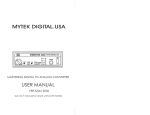
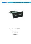
Mytek Stereo 192 Sample Rate Converter – User Manual
Stereo 192 Sample Rate Converter
User Manual
ver. 1.2 / May 2011
© Mytek Digital 2011
www.mytekdigital.com
Page: 1 / 12
Mytek Stereo 192 Sample Rate Converter – User Manual
This manual may be updated
Download the newest version at:
http://www.mytekdigital.com/download_library/
For technical support, technical tips and support check:
http://www.mytekdigital.com
or contact Mytek tech support at:
[email protected]
or at:
tel. (347) 384-2687
fax. (212) 202-5331
Mytek Digital
148 India St. FL 1
Brooklyn, NY 11222
USA
www.mytekdigital.com
Page: 2 / 12
Mytek Stereo 192 Sample Rate Converter – User Manual
Content
Introduction..................................................................................4
Quick Start....................................................................................5
Front Panel....................................................................................6
Back Panel.....................................................................................7
Functions.......................................................................................7
Frequency Selections...................................................................8
Mode Selections..........................................................................10
Error Messages...........................................................................10
Important Safety Instructions...................................................11
www.mytekdigital.com
Page: 3/12
Mytek Stereo 192 Sample Rate Converter – User Manual
Introduction
The Mytek Stereo 192 Sample Rate Converter is a hardware
SRC that is capable of synchronous and asynchronous
operation. It can convert between any frequency between
32,000 Hz and 192,000 Hz with 1 Hz accuracy.
The Stereo 192 SRC accepts AES/EBU, S/PDIF, and Toslink
input, and has AES/EBU and S/PDIF (coax only) output. There
are also Wordclock In and Out connections.
www.mytekdigital.com
Page: 4/12
Mytek Stereo 192 Sample Rate Converter – User Manual
Quick Start
1. Connect Digital Input and Output
Connect the output of your digital device to an input on the SRC.
Select this input on the front panel with the “IN” button. A solid
LED will tell you that the source is valid. Connect the digital output
of the SRC to the digital receiving device.
2. Operation
You can choose to display either the input frequency or the
output frequency by pressing the “F-DISP” button. The unit
will convert the signal once a valid input and frequency is
selected.
3. Configuration
Using the “SEL” and “UP” buttons will allow you to cycle
through and select the various frequency options. Holding
down the “SEL” button until the first digit on the display
flashes will let you define a custom frequency with the “UP”
button to change the value and the “SEL” button to select the
next digit. Push “SEL” after the last digit to confirm your
value.
The “MODE” button cycles between Synchronous (SNC),
Asynchronous – Internal Crystal (ASNC-XTL), and
Asynchronous – External Wordclock (ASNC-WCK).
For user defined
frequencies less than
100,000 the left most digit
will be blank but it is still
cycled through with the
“SEL” button. The value
set won't be confirmed
until you push the “SEL”
button after the last digit.
The “OUTPUT WORD LENGTH” button will select between
24, 20, or 16 bits output format. TPDF dithering is applied to
20 and 16 bits.
www.mytekdigital.com
Page: 5/12
Mytek Stereo 192 Sample Rate Converter – User Manual
Front Panel
AS YNCHRONOUS AND
S YNCHRONOUS S RC
STEREO192SRC
MYTEK DIGITAL.USA
C
192000
AES
IN
SPDIF
F-DISP
A
B
SEL
UP
SNC
MO DE
F-O UT
TO SLINK
A
F-IN
0
D
E
ASNC-XTL
O UTPUT
WO RD
LENGTH
ASNC-WCK
F
G
H
I
J
16
-3
20
-20
24
-60
K
L
I
O
M
A – Input selector button
B – Input status LED
C – LED Display
D – Frequency display selector button
E – Frequency display status LED
F – Select button
G – Up button
H – Mode selector button
I – Mode status LED
J – Output word length selector button
K – Output word length status LED
L – L/R signal meter
M – On/Off switch
www.mytekdigital.com
Page: 6/12
Mytek Stereo 192 Sample Rate Converter – User Manual
Back Panel
110/220VAC
AES OUT
AES IN
B
WCK
IN
S PDIF
IN TOS LINK IN
A
C
WCK
O UT
G
D
E
SWITCH AND FUSE INSIDE
DESIGNED IN USA
F
WWW.MYTEKDIGITAL.CO M
S PDIF
OUT
H
A – IEC Power socket
B – Wordclock BNC Input
C – Wordclock BNC Output
D – AES/EBU XLR Input
E – S/PDIF Coax Input
F – S/PDIF Optical Input (Toslink)
G – AES/EBU XLR Output
H – S/PDIF Coax Output
Functions
IN – You can select the active input by pressing this button.
The status LED will have a solid glow when there is a valid
incoming signal and it's frequency will be displayed when you
have F-IN selected as the F-DISP. If no signal is present the
LED will be blinking and “no In” will be displayed.
F-DISP – This selects whether the input or output frequency is
shown on the display.
SEL and UP – These buttons allow you to cycle through the
various menu options, frequencies, and make selections.
MODE – This chooses whether you want the SRC to function
synchronously, asynchronously with internal crystal as the
clock source or asynchronously with external wordclock as the
clock source.
OUTPUT WORD LENGTH – This chooses between 24, 20,
and 16 bits as the word length.
www.mytekdigital.com
Page: 7/12
Mytek Stereo 192 Sample Rate Converter – User Manual
Frequency Selections
There are 3 modes of frequency selection:
Quick – pressing the UP button will cycle between
•
44100 Hz
•
48000 Hz
•
88200 Hz
•
96000 Hz
•
176400 Hz
•
192000 Hz
•
last user defined entry
Additional Predefined – pressing SEL will bring up the
available frequency subgroups. UP will cycle between:
•
STD (standard)
•
P. down (pull down)
•
P. up (pull up)
Pressing SEL will select the subgroup. Now use UP to cycle
between the following choices:
•
•
STD
◦
44100 Hz
◦
48000 Hz
◦
88200 Hz
◦
96000 Hz
◦
176400 Hz
◦
192000 Hz
P. down
◦
42336 Hz
◦
44056 Hz
◦
46080 Hz
◦
47952 Hz
www.mytekdigital.com
Page: 8/12
Mytek Stereo 192 Sample Rate Converter – User Manual
•
P. up
◦
44144 Hz
◦
45937 Hz
◦
48048 Hz
◦
50000 Hz
Once the desired frequency is selected push SEL to confirm.
Custom Value – hold down SEL until the first digit starts
flashing. Press UP to set the desired digit value. Press SEL to
confirm the value and move on to the next digit. After the
most significant digit is set the unit is now ready for
operation.
The minimum frequency that can be set is 32000 Hz. The
maximum is 192000 Hz.
Upon selection of the frequency the display will adjust to the
selected value once the PLL is locked to the frequency.
www.mytekdigital.com
For user defined
frequencies less than
100,000 the left most digit
will be blank but it is still
cycled through with the
“SEL” button. The value
set won't be confirmed
until you push the “SEL”
button after the last digit.
Page: 9/12
Mytek Stereo 192 Sample Rate Converter – User Manual
Mode Selections
The Stereo 192 SRC is capable of synchronous or
asynchronous operation.
Synchronous operation means that the output clock is locked
to and following the input clock, even if it's a different
frequency. This mode should be used when the actual length
in time of the output sound clip has to be exactly the same
(+/- 1 sample) as the original. Generally this mode should be
used for any digital to digital transfers such as the output
being re-recorded digitally.
Asynchronous operation means that the output clock is
independent (not synchronized) from the input clock. This
would be used when up-sampling a signal to be converted by
a DA converter for example. It can be set to use the ultra-low
jitter clock from the internal quartz oscillator or it can use
external wordclock.
If the digital source has a
jittery clock then using
synchronous mode will
retain some of that jitter.
Asynchronous mode does
not carry over jitter.
When synched to external wordclock the frequency is set by
the incoming clock signal. You will not be able to change the
frequency on the front panel.
Error Messages
no in – This is displayed when a valid input is not present.
no out – This is displayed if you are in ASNC-WCK mode and
there is no external clock source present.
www.mytekdigital.com
Page: 10/12
Mytek Stereo 192 Sample Rate Converter – User Manual
Important Safety Instructions
• Read these instructions.
• Keep these instructions.
• Heed all warnings.
• Follow all instructions.
• Do not use this apparatus near water.
• Clean only with dry cloth.
• Do not block any ventilation openings. Install in accordance with the
manufacturer's instructions.
• Do not install near any heat sources such as radiators, heat registers,
stoves, or other apparatus (including amplifiers) that produce heat.
• Do not defeat the safety purpose of the polarized or grounding-type
plug. A polarized plug has two blades with one wider than the other. A
grounding-type plug has two blades and a third grounding prong. The
wide blade or the third prong are provided for your safety. If the
provided plug does not fit into your outlet, consult an electrician for
replacement of the obsolete outlet.
• Protect the power cord from being walked on or pinched particularly
at plugs, convenience receptacles, and the point where they exit from
the apparatus.
• Only use attachments/accessories specified by the manufacturer.
• When a cart is used, use caution when moving the cart/apparatus
combination to avoid injury from tip-over.
• Unplug this apparatus during lightning storms or when unused for
long periods of time.
• Refer all servicing to qualified service personnel. Servicing is required
when the apparatus has been damaged in any way, such as powersupply cord or plug is damaged, liquid has been spilled or objects have
fallen into the apparatus, the apparatus has been exposed to rain or
moisture, does not operate normally, or has been dropped.
www.mytekdigital.com
Page: 11/12
Mytek Stereo 192 Sample Rate Converter – User Manual
WARNING
Excessive sound pressure from speakers and headphones can cause
hearing loss. In order to use this product safely, avoid prolonged
listening at excessive sound pressure levels.
For the customers in the U.S.A.
This equipment has been tested and found to comply with the limits for
a Class A digital device, pursuant to Part 15 of the FCC Rules. These
limits are designed to provide reasonable protection against harmful
interference when the equipment is operated in a commercial
environment. This equipment generates, uses, and can radiate radio
frequency energy and, if not installed and used in accordance with the
instruction manual, may cause harmful interference to radio
communications.
You are cautioned that any changes or modifications not expressly
approved in this manual could void your authority to operate this
equipment.
All interface cables used to connect peripherals must be shielded in
order to comply with the limits for a digital device pursuant to Subpart
B of Part 15 of FCC Rules.
This device complies with Part 15 of the FCC Rules. Operation is subject
to the following two conditions: (1) this device may not cause harmful
interference, and (2) this device must accept any interference received,
including interference that may cause undesired operation.
This product with the CE marking complies with the EMC Directive
issued by the Commission of the European Community. Compliance
with this directive implies conformity to the following European
standards:
• EN55103-1 : Electromagnetic Interference (Emission)
• EN55103-2 : Electromagnetic Susceptibility (Immunity)
This product is intended for use in the following Electromagnetic
Environments: E1 (residential), E2 (commercial and light industrial), E3
(urban outdoors), E4 (controlled EMC environment, ex. TV studio).
www.mytekdigital.com
Page: 12/12