1
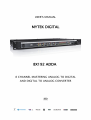
Mytek 8x192 ADDA – User's Manual
User's Manual ver. 1.2 / September 2015
© Mytek 2015
There are periodic updates to this manual.
To download the latest version, technical support, and for setup tips
please visit:
http://www.mytekdigital.com
or call us at:
tel. +1 (347) 384-2687
Mytek Digital
148 India St.
Brooklyn, NY 11222
USA
www.mytekdigital.com
Page: 1/19
Mytek 8x192 ADDA – User's Manual
Owner's record
The serial number is located on the bottom of the unit. We suggest you record the serial number
in the space provided below. The firmware version label is located on the 8 pin emprom chip
located in a socket under the top lid. The firmware can be updated and chip replaced by the user if
necessary. Please be sure to return your completed warranty card.
8x192 ADDA Serial NO.:
Firmware Version:
Purchase Date:
Dealer/ Contact:
Cards Installed, Serial ##
Contents
1. Introduction ........................................................................................ 3
2. Package contents ................................................................................ 3
3. Signal flow .......................................................................................... 4
4. Block schematics ................................................................................. 5
5. Back panel connections ....................................................................... 6
6. Front panel controls ............................................................................ 7
7. Input / output gain and other internal adjustments ............................. 8
8. Setting Clocks and Signal Sources ...................................................... 10
9. Updating the firmware ....................................................................... 14
10. Expansion cards ................................................................................ 16
11. Specifications .................................................................................... 16
12. Warranty ........................................................................................... 18
13. Important safety informations ........................................................... 18
14. Information on Disposal for Users of Waste ....................................... 19
www.mytekdigital.com
Page: 2/19
Mytek 8x192 ADDA – User's Manual
1. Introduction
Mytek 8X192 ADDA is an 8 channel Analog to Digital and an 8 channel Digital to Analog converter
maticoulsly designed to provide the highest quality signal path. No compromises have been made
to sound quality, and we feel that this is the best sounding Mytek converter to date. In trial tests in
comparison with other hi-end brands this unit provided the same or better sonic performance,
which makes it suitable for the most demanding mastering and recording applications.
Users choose Mytek converters primarily for their outstanding sonic quality. The sound of Mytek
converters can best be described as "transparent". We design our converters to be as faithful to the
original signal as possible, rather than adhering the philosophy of some other manufacturers who
offer "analog" or "tube" sounding converters. Mytek converters are designed to be as close to a
straight wire as possible,which is especially evident when used at full 24/192 or DSD resolution.
On the Mytek website you can find and download various sound samples to evaluate the 8X192's
sound quality and compare it to the sound of other high end converter units. Please log onto:
http://www.mytekdigital.com to download samples. Thanks to the wide choice of daughter
interface cards (DIO Cards), the 8X192 becomes an 8 channel "digital swiss army knife",which
allows the user to adapt converter performance to most studio setups and situations."
In addition to typical converter functions, the Mytek 8X192 features a unique analog mix bus
designed with transparency in mind, a monitor section with a mastering grade stepped attenuator,
and a hi-end headphone amp.
The built in CX 797 clock generator with multiple wordclock outputs is the best source for stable
studio house clock, and the 8x192 will perform best using this internal clock.
2. Package Contents
•
the 8x192 ADDA converter
•
power cord
•
manual
www.mytekdigital.com
Page: 3/19
Mytek 8x192 ADDA – User's Manual
3. Signal flow
The 8X192 ADDA has two independent signal paths within the unit. They offer independent signal
paths but must operate at the same clock source and sampling frequency. It's recommended that
as much as possible the unit should be clocked from its internal CX 797 clock generator. This
mode offers minimum jitter allowin for the best performance and system stability. Associated
equipment should be slaved to 8X192 clock outputs whenever possible. There is no measurable
improvement (rather typically a degradation) when the unit is clocked by external clock generator.
1. The first path is built around the ADC converter and essentially defines what input is
selected to be sent to digital outputs. All digital outputs are simultaneous, so if the analog
input is engaged, the analog signal is converted to digital and sent to all installed digital
outputs.
If the digital input is selected, only digital format conversion is performed, and the signal is
then passed to the digital outputs. There is no SRC or any kind of digital processing
induced. When operating in DSD mode only the inputs and outputs compatible with DSD
format are active.
2. The second signal path is built around the DAC. It defines what signal is present at the
analog outputs. The selected digital signal is converted to analog. If the analog input is
selected, it's first converted to digital by the ADC and then sent to the DAC and converted
back to analog.
www.mytekdigital.com
Page: 4/19
Mytek 8x192 ADDA – User's Manual
4. Block schematic
www.mytekdigital.com
Page: 5/19
Mytek 8x192 ADDA – User's Manual
5. Back Panel Connections
www.mytekdigital.com
Page: 6/19
Mytek 8x192 ADDA – User's Manual
6. Front Panel Controls
www.mytekdigital.com
Page: 7/19
Mytek 8x192 ADDA – User's Manual
7. Input / output gain and other internal adjustments
7.1 Analog input/output alingment
The 8X192 ADDA analog input/output sensitivity comes as factory default fixed at -15dBFs
corresponding to +4dB (OVU=1.228VRMS measured between hot and cold). This gain is optimal
for most situations and unless another level "is necessary for systemic reasons, we recommend
leaving the gain at the default setting. If the gain has to be changed the appriopriate jumpers and
trimpots have to be accessed by lifting the top cover. Please review the drawing on following page.
The gain alignment does not affect audio quality, only input/output sensitivity. A small tweaker or
screwdriver is necessary. First you have to arbitrarily decide what will be your studio "0 VU"
analog/digital reference level. It is usually between -20 and -14dB. It defines how much headroom
is left over the normal operating "0 VU" level. You may set it at the same level as other piece of
equipment in your studio.
Step 1 - Analog output alignment
1. Play a digital audio source (DAW generator, test CD etc.) set to approx. 1kHz at the
peak operating level you have chosen (let's say you have chosen -18dB).
2. Send the signal from the analog output to the console VU meter. If you don't have a
VU meter you can use an AC voltmeter set to measure AC RMS values. "0 VU"at +
4dB corresponds to 1.225 Volts RMS measured between pin hot and pin cold of the
output signal.
3. Using a tweaker or a small screwdriver adjust the analog outputs until the VU meter
reads "0 VU".
4. Repeat the same for all outputs.
Step 2 - Analog input alingment
1. Set the oscillator in your console at 1kHz and "0 VU". Send the oscillator to the
8X192ADDA analog input."0 VU" at + 4dB corresponds to 1.225 Volts RMS
measured between pin 2 and 3 of the output XLRs. If you do not have an analog
oscillator, you can use a calibrated analog out of a DA converter and generate a
sinewave inside the DAW. Alternatively, if you do not have an oscillator you can use
the analog outputs you have just aligned as a source of a sinewave at +4dB
(generating sinewave digitally as in step 1).
2. Select the "analog input". Connect a digital meter to a digital output. If you don't
have a dedicated digital meter use the most precise meter available in you existing
digital recording equipment or DAW.
3. Adjust the analog input level to get appropriate reading of the meter (for example
-18dB).
4. Repeat the same for all of the analog inputs.
www.mytekdigital.com
Page: 8/19
Mytek 8x192 ADDA – User's Manual
7.2 Other internal adjustments
www.mytekdigital.com
Page: 9/19
Mytek 8x192 ADDA – User's Manual
8. Setting clocks and signal sources
8.1 Normal operation; AD & DA switched to internal clock, AD feeding the recorder and DA
monitoring recorder.
In this mode both the AD and DA run on the internal clock. This mode provides the lowest jitter
and most sonically robust performance. External recorders (such as DAW etc) have to be
synchronized either to the AD digital outputs (any format: AES or DIOCARD1 or DIOCARD2) or to
the converter Worclock output.
This example shows 44.1 PCM, but any FS can be any selected, including DSD and 128x DSD. Also
instead of AES, any other digital input to DA can be selected, depending on the particular system
configuration. The unit will output on its BNC outs Wordclock corresponding to the sampling
frequency unless it's divided by using WCK button.
If the DA converter receives no selected digital in OR this input is not synchronous with AD clock,
the LED will flash and DA converter will mute.
8.2 Feed through operation; AD & DA clocked internally, AD feeding DA directly
In this mode both the AD and DA run on the internal clock. This mode also provides the lowest
jitter and most sonically robust performance. External recorders (such as DAW etc) must be
synchronized either to AD digital outputs (any format: AES or DIOCARD1 or DIOCARD2) or to the
converter Worclock output.
In this mode signal is fed from AD to digital outputs and also to DA directly. This mode may be
usefull when conversion latency has to be minimized during the recording. It functionally
corresponds to a multitrack tape machine always on "input". This example shows 44.1 PCM, but
any FS can be any selected, including DSD and 128xDSD. Also instead of AES any other digital
input to DA can be selected depending on particular system configuration. The unit will output on
its BNC outs Wordclock corresponding to the sampling frequency unless it's divided by using WCK
button.
www.mytekdigital.com
Page: 10/19
Mytek 8x192 ADDA – User's Manual
8.3 Normal operation; AD & DA on external WordClock, AD feeding the recorder and DA
In this mode both the AD and DA run on an external clock. Holding the "Ext. Clock Source" button
selects this mode. Although this mode does not provide the lowest jitter performance it might be
desirable for systemic reasons. External recorders (such as DAW etc) can be synchronized to
external wordclock sources OR AD digital outputs (any format: AES or DIOCARD1 or DIOCARD2)
OR to converter Worclock output.
This example shows 44.1 PCM, but any FS can be selected, including DSD and 128xDSD. Also
instead of AES any other digital input to DA can be selected depending on a particular system
configuration.
The unit will output on its BNC Wordclock outs corresponding to the sampling frequency provided
externally unless it's divided by using WCK button. If the DA converter receives no selected digital
in OR this input is not synchronous with AD clock, the LED will flash and DA converter will mute.
Sample Rate has to be selected manually to match wck or its nearest approximation. WCK will be
the base of sampling rate. If no WCK source is detected, WCK LED will flash and the unit will not
pass signal.
8.4 Feed through operation; AD & DA on external clock, AD feeding DA directly.
In this mode both the AD and DA run on an external clock. Although this mode does not provides
the lowest jitter performance it might be desirable for systemic reasons. External recorders (such
as DAW etc.) can be synchronized to an external wordclock source OR AD digital outputs (any
format: AES or DIOCARD1 or DIOCARD2) OR to a converters Worclock output. In this mode signal
is fed from the AD to digital outputs and also to DA directly. This mode may be useful when
conversion latency has to be minimized during the recording. It functionally corresponds to a
multitrack tape machine always being on "input".
This example shows 44.1 PCM, but any FS can be selected, including DSD and 128xDSD. Also
instead of AES any other digital input to DA can be selected depending on a particular system
configuration.
www.mytekdigital.com
Page: 11/19
Mytek 8x192 ADDA – User's Manual
The unit will output on its BNC outs a Wordclock signal corresponding to the sampling frequency
provided externally, unless it's divided by using the WCK button. If the DA converter receives no
selected digital in OR this input is not synchronous with AD clock, the LED will flash and DA
converter will mute. The Sample Rate has to be selected manually to match wck or its nearest
approximation. WCK will be the base of sampling rate. If no WCK source is detected, the WCK LED
will flash and the unit will not pass signal.
8.5 Normal operation; AD & DA on external clock other than WCK, AD feeding the recorder and DA
monitoring recorder.
In this mode both the AD and DA run on an external clock. Although this mode does not provides
the lowest jitter performance it might be desirable for systemic reasons. For example a second
8X192 unit running can be coupled with a master 8X192 unit via Firewire cable only. In this case
the clock for the second unit is provided via a Firewire card (DIOCARD1 in this example). External
recorders (such as DAW etc) can be either AD digital outputs (any format: AES or DIOCARD1 or
DIOCARD2), converter Worclock outputs, or can run in asynchronous Firewire mode.
This example shows 44.1 PCM, but any FS can be any selected, including DSD and 128xDSD. Also
instead of AES any other digital input to DA can be selected depending on a particular system
configuration.
The unit will output on its BNC outs Wordclock corresponding to the sampling frequency provided
externally unless it's divided by using WCK button. If the DA converter receives no selected digital
in OR this input is not synchronous with AD clock, the LED will flash and DA converter will mute.
The Sample Rate has to be selected manually to match wck or its nearest approximation. WCK will
be the base of sampling rate. If no WCK source is detected, WCK LED will flash and unit will not
pass signal.
8.6 Feed through operation; AD & DA on internal clock, AD feeding DA directly
In this mode both the AD and DA run on an external clock. Although this mode does not provides
the lowest jitter performance it might be desirable for systemic reasons. For example a second
8X192 unit running can be coupled with a master 8X192 unit via a Firewire cable only. In this case
the clock for second unit is provided via Firewire card (DIOCARD1 in this example).
www.mytekdigital.com
Page: 12/19
Mytek 8x192 ADDA – User's Manual
External recorders (such as DAW etc) can be either AD digital outputs (any format: AES or
DIOCARD1 or DIOCARD2), converter Worclock output, or can run in asynchronous Firewire mode.
In this mode signal is fed from AD to digital outputs and also to DA directly. This mode may be
usefull when conversion latency has to be minimized during the recording. It functionally
corresponds to a multitrack tape machine always on"input".
This example shows 44.1 PCM, but any FS can be any selected, including DSD and 128xDSD. Also
instead of AES any other digital input to DA can be selected depending on a particular system
configuration.
The unit will output on its BNC outs Wordclock corresponding to the sampling frequency provided
externally unless it's divided by using WCK button. If the DA converter receives no selected digital
in OR this input is not synchronous with AD clock, the LED will flash and DA converter will mute.
The Sample Rate has to be selected manually to match wck or its nearest approximation. WCK will
be the base of sampling rate. If no WCK source is detected, WCK LED will flash and unit will not
pass signal.
8.7 Format conversion operation; ADC is OFF, digital IN to digital OUT, DA monitoring digital IN
In this mode the 8X192 unit can be used for format conversion between all installed digital
interfaces. Once a digital input is selected for "SOURCE TO DIGITAL", the "SAMPLE RATE" switch is
disabled and EXT.CLOCK SOURCE and SOURCE TO ANALOG OUT automatically set to selected
digital input. The incoming digital signal is converted to all available digital formats
simultanouesly as well as is sent to DA converter for monitoring. The wck divider affects only WCK
outs. WCK is derives from incoming digital input, in this example DIOCARD1.
www.mytekdigital.com
Page: 13/19
Mytek 8x192 ADDA – User's Manual
9. Updating the firmware
This update might be necessary to bring the converter's motherboard up to date to allow its
operation with an expanson card of your choice. Generally installed firmware should be of rev. 6.0
or greater. Contact Mytek via email to obtain current firmware chip.
WARNING!
Remember to follow basic safety rules about handling of electronic device while opening the
converter:
•
keep your hands dry,
•
remember to turn off power and disconnect power and signal cables while working with the
top cover removed.
Please follow steps below to perform firmware update of 8X192 ADDA converter.
A. Check if the power cord and signal and clock lines are disconnected.
B. Remove the top lid.
C. Locate the memory socket on the converter main board
www.mytekdigital.com
Page: 14/19
Mytek 8x192 ADDA – User's Manual
D. Gently remove old memory chip.
E. Carefully insert new memory chip in the socket. The chip slot (pin1) should be matching
the socket slot ie must be facing back of the unit. If necessary gently manually bend pins
inward, to match the holes in the slot. During installation check correct chip position.
F. Mount the top lid back.
www.mytekdigital.com
Page: 15/19
Mytek 8x192 ADDA – User's Manual
G. Attach power cord and other cabling.
H. Turn on the converter.
For about 2 seconds no LED should be lit on the converter’s front panel, as new software is copied
from memory to the main board chips. Then, all LEDs should turn on momentarily for about
10-20sec and subsequently the unit should begin normal operation.
10. Expansion cards
There are following cards available:
DIO FW, DIO USB2, DIO MADI, DIO ADAT, *DIO DSD/SDIF, *DIO SONOMA, *DIO DANTE, DIO HDX
FW, USB2, MADI, ADAT and HDX DIO cards can be ordered with the 8X192 ADDA with no
additional charge. Cards marked with * can not be a part of the bundle and can only be purchased
separately.
Note! - DIO HDX expansion card must be mounted in first slot only.
12. Technical Specifications
AD Section
Conversion:
Linear, 1 Bit *, 128x oversampling at 44.1-48kHz, 64x oversampling
at 88.2-192kHz, optional 64xDSD and 128xDSD
Resolution:
Sample rates:
24 bit, ( or 1 bit DSD)
44.1kHz, 48kHz, 88.2kHz, 96kHz, 176.4kHz, 192kHz or wordclock
25-200kHz
Dynamic Range:
120dB A-weighted, 117dB Total
THD+Noise:
-106dB (<0.0005%)
Internal clock jitter:
<10picoseconds
Analog Inputs:
+4dBm balanced or unbalanced, 10 kOhm
* This ADC uses a 1 bit delta sigma modulator which achieves instristically better low level linearity than the multibit
counterparts. Although multibit ADC THD measurements are marginally better, the distribution of distortion subjectively
sounds less desirable than in 1 bit converter which tends to exhibit certain silky quality. The same, currently worlds'
highest performance 1 bit modulator is used to produce genuine 1 bit DSD signal.
www.mytekdigital.com
Page: 16/19
Mytek 8x192 ADDA – User's Manual
DA Section
Conversion:
Linear, multibit delta-sigma PCM and 64xDSD and 128xDSD
Resolution:
24 bit, ( or 1 bit DSD)
Sample rates:
44.1kHz, 48kHz, 88.2kHz, 96kHz, 176.4kHz, 192kHz or wordclock
25-200kHz
Dynamic Range:
123dB A-weighted, 120dB Total
THD+Noise:
-110dB (<0.0004%)
Internal clock jitter:
<10picoseconds
Analog Outputs:
+4dBm balanced or unbalanced, 75 Ohm
Digital outputs:
Hi-Speed AES/EBU built in up to 200k or dual wire for 4 chan
Others
operation; other formats on optional DIO Cards
Expansion cards:
DIO HDX, DIO MADI, DIO USB2.0, DIO FW, DIO SONOMA, DIO DANTE,
DIO ADAT, DIO DSD/SDIF.
External Sync:
Wordclock IN and OUT or 256x Superclock
WordClock OUT
used as house clock: 15 LS TTL loads max. / can be terminated with 75 Ohm / 6 OUTs
WordClock IN:
TTL/5V input- internally switchable termination 75 Ohm.
Wordclock can be replaced by Superclock fiunction.
Power supply:
100/115V-220/240V 50/60Hz switchable
Weight:
14 pounds [ 7 kg ]
Dimensions:
1U x 19 inch x 10.5 inch deep
www.mytekdigital.com
Page: 17/19
Mytek 8x192 ADDA – User's Manual
13. Warranty
This 8x192ADDA digital audio converter is warranted by Mytek to the original purchaser against
defects in workmanship and materials used in manufacture for a period of two years from the date
of purchase. Faults due to customer misuse, unauthorized modifications or accidents are not
covered by this warranty. No other warranty is expressed or implied.
Any faulty unit should be sent, shipping prepaid to the manufacturer service center. Prior to
shipping the client must obtain an RMA nymber from Mytek for warranty services. Units sent
without RMA number will not be accepted.
Mytek extends affordable repair service for all units manufactured to date that are not covered by
this Warranty. Mytek repair centers are located at Mytek Headquarters in Brooklyn, New York, and
in Warsaw, Poland (at Mytek EU Distribution Office).
14. Important safety informations
•
Read these instructions.
•
Keep these instructions.
•
Heed all warnings.
•
Follow all instructions.
•
Do not use this device near water.
•
Clean only with dry cloth.
•
Do not block any ventilation openings. Install in accordance with the manufacturer's
instructions.
•
Do not install near any heat sources such as radiators, heat registers, stoves, or other
apparatus (including amplifiers) that produce heat.
•
Do not defeat the safety purpose of the polarized or grounding-type plug. A polarized plug
has two blades with one wider than the other. A grounding-type plug has two blades and a
third grounding prong. The wide blade or the third prong are provided for your safety. If
the provided plug does not fit into your outlet, consult an electrician for replacement of the
obsolete outlet.
•
Protect the power cord from being walked on or pinched particularly at plugs, convenience
receptacles, and the point where they exit from the apparatus.
•
Only use attachments/accessories specified by the manufacturer.
•
When a cart is used, use caution when moving the cart/apparatus combination to avoid
injury from tip-over.
•
Unplug this apparatus during lightning storms or when unused for long periods of time.
•
Refer all servicing to qualified service personnel. Servicing is required when the apparatus
has been damaged in any way, such as power-supply cord or plug is damaged, liquid has
been spilled or objects have fallen into the apparatus, the apparatus has been exposed to
rain or moisture, does not operate normally, or has been dropped.
www.mytekdigital.com
Page: 18/19
Mytek 8x192 ADDA – User's Manual
15. Warning
Excessive sound pressure from speakers and headphones can cause hearing loss. In order to use
this product safely, avoid prolonged listening at excessive sound pressure levels.
For the customers in the U.S.A.
This equipment has been tested and found to comply with the limits for a Class A digital device,
pursuant to Part 15 of the FCC Rules. These limits are designed to provide reasonable protection
against harmful interference when the equipment is operated in a commercial environment. This
equipment generates, uses, and can radiate radio frequency energy and, if not installed and used
in
accordance
with
the
instruction
manual,
may
cause
harmful
interference
to
radio
communications.
You are cautioned that any changes or modifications not expressly approved in this manual could
void your authority to operate this equipment.
All interface cables used to connect peripherals must be shielded in order to comply with the
limits for a digital device pursuant to Subpart B of Part 15 of FCC Rules.
This device complies with Part 15 of the FCC Rules. Operation is subject to the following two
conditions: (1) this device may not cause harmful interference, and (2) this device must accept any
interference received, including interference that may cause undesired operation.
This product with the CE marking complies with the EMC Directive issued by the Commission of
the European Community. Compliance with this directive implies conformity to the following
European standards:
• EN55103-1 : Electromagnetic Interference (Emission)
• EN55103-2 : Electromagnetic Susceptibility (Immunity)
This product is intended for use in the following Electromagnetic Environments: E1 (residential), E2
(commercial and light industrial), E3 (urban outdoors), E4 (controlled EMC environment, ex. TV
studio).
16. Information on Disposal for Users of Waste
Electrical & Electronic Equipment
(private households).
The Wheelie Bin symbol on the products and/or accompanying documents means that used
electrical and electronic products should not be mixed with general household waste. Disposing of
this product correctly will help save valuable resources and prevent any potential negative effects
on human health and the environment.
To properly dispose harmful substances and recycle the product, the user is obliged to return it at
the point of collection of electrical and electronic equipment waste. For more information please
contact your local authorities, waste disposal units or retailer.
www.mytekdigital.com
Page: 19/19