1
2.7 Installing DIMMs
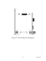
The procedure for installing DIMMs is described below. Please follow
these steps carefully. The number of pins are different on either side of
the breaks, so the module can only fit in one way. DIMM modules have
different pin contacts on each side, and therefore have a higher pin density.
1.
Make sure that the two handles of the DIMM socket are in the
“open” position. i.e. The handles remain leaning outward.
2.
Slowly slide the DIMM module along the plastic guides on both
ends of the socket.
3.
Press the DIMM module right down into the socket, until you hear
a click. This is when the two handles have automatically locked the
memory module into the correct position of the socket.
To remove the memory module, just push both handles outward, and the
module will be ejected from the socket.
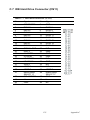
2.8 IDE, CDROM hard drive connector (CN11)
The PCM-9373 provides 1 IDE channels which you can attach up to two
Enhanced Integrated Device Electronics hard disk drives or CDROM to
the PCM-9373’s internal controller. The PCM-9373's IDE controller uses
a PCI interface. This advanced IDE controller supports faster data transfer, PID mode 3, mode 4 and up to UDMA/33.
2.8.1 Connecting the hard drive
Connecting drives is done in a daisy-chain fashion. This package includes
1 44PIN IDE cable that can connect to 1.8" and 2.5" drives.
1.
Connect one end of the cable to CN11. Make sure that the red (or
blue) wire corresponds to pin 1 on the connector, which is labeled
on the board (on the right side).
2.
Plug the other end of the cable into the Enhanced IDE hard drive,
with pin 1 on the cable corresponding to pin 1 on the hard drive.
(See your hard drive’s documentation for the location of the connector.)
15
Chapter 2