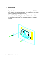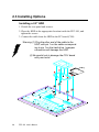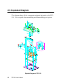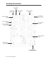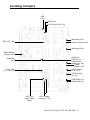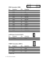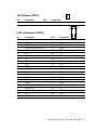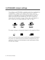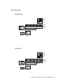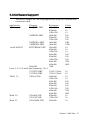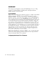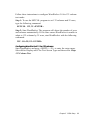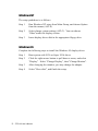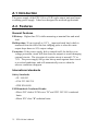
1
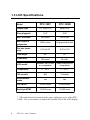
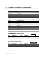
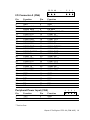
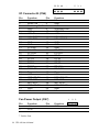
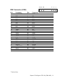
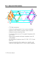
PPC-100
486-based Panel PC with 10.4"
LCD display
Copyright Notice
This document is copyrighted, 1997, by Advantech Co. Ltd. All rights
are reserved. Advantech Co., Ltd. reserves the right to make improvements to the products described in this manual at any time without notice.
No part of this manual may be reproduced, copied, translated or transmitted in any form or by any means without the prior written permission of
Advantech. Information provided in this manual is intended to be
accurate and reliable. However, Advantech assumes no responsibility for
its use, nor for any infringements upon the rights of third parties which
may result from its use.
All brand and product names mentioned herein are trademarks or
registered trademarks of their respective holders.
FCC Class B
Note: This equipment has been tested and found to comply with the
limits for a Class B digital device, pursuant to part 15 of the FCC Rules.
These limits are designed to provide reasonable protection against
harmful interference in a residential installation. This equipment generates, uses and can radiate radio frequency energy and , if not installed and
used in accordance with the instructions, may cause harmful interference
to radio communications. However, there is no guarantee that interference will not occur in a particular installation. If this equipment does
cause harmful interference to radio or television reception, which can be
determined by turning the equipment off and on, the user is encouraged to
try to correct the interference by one or more of the following measures:
• Reorient or relocate the receiving antenna.
• Increase the separation between the equipment and receiver
• Connect the equipment into an outlet on a circuit different from
that to which the receiver is connected
• Consult the dealer or an experienced radio/TV technician for
help.
Part No. 2002100020, 2nd Edition
Printed in Taiwan, April 1997
ii
Packing List
Before installing your panel PC, ensure that the following materials have been received:
PPC-100
Utility Disks
User‘s Manual
Accessories for PPC-100
•I/O socket
•FDD flat cable (35 cm)
•FDD power wire (35 cm)
•HDD flat cable (15 cm)
•Power cord (1.8 m)
•Assembly mounting parts
•Heat Sink
Note: If you install a 486 or 5x86 series CPU, you must install a
HeatSink above the CPU in order to avoid heat damage.
If any of these items are missing or damaged, contact your
distributor or sales representative immediately.
iii
Contents
Chapter 1: General Information ................................. 1
1.1 Introduction ...................................................................... 2
1.2 Specifications .................................................................... 3
1.3 LCD Specifications .......................................................... 6
1.4 Dimensions ........................................................................ 7
1.5 I/O Arrangement.............................................................. 8
1.6 Cutout (suggestion) .......................................................... 9
1.7 Mounting ......................................................................... 10
Chapter 2: System Setup ........................................... 11
2.1 General ............................................................................ 12
2.2 Removing Rear Panel .................................................... 13
2.3 Installing Options ........................................................... 14
2.4 Installing Software to the HDD .................................... 17
2.5 Exploded Diagram ......................................................... 18
2.6 PCM-4865 and I/O Adapter Replacement ................. 19
2.7 Power Supply and Cooling Fan Replacement ............. 21
Chapter 3: The Engine of PPC-100 (PCM-4865) ......... 23
3.1 Introduction .................................................................... 24
3.2 Features ........................................................................... 25
3.3 PCM-4865 Connector Pin Assignment ........................ 28
3.4 PCM-4865 Jumper settings ........................................... 34
Chapter 4: Software Configuration ......................... 47
4.1 Introduction .................................................................... 48
4.2 Utility disk ...................................................................... 48
4.3 Ethernet Utility Disk ...................................................... 51
iv
Chapter 5: SVGA Setup ............................................... 55
5.1 Introduction ....................................................................
5.2 Sleep Mode ......................................................................
5.3 Simultaneous Display Mode ..........................................
5.4 Software Support ...........................................................
5.5 Driver Installation ..........................................................
56
56
56
57
58
Appendix A: Power Supply Specifications .............. 71
Appendix B: Touchscreen (Optional) ........................ 75
Appendix C: Programming the Watchdog Timer .... 79
Appendix D: 4 Digital Isolated I/O Interface ............ 81
Appendix E: Monochrome LCD Display .................... 83
v
CHAPTER
1
General
Information
This chapter gives background information on the PPC-100
Sections include:
• Introduction
• Specifications
• LCD Specifications
• Dimensions
• I/O Arrangement
• Cutout (suggestion)
• Mounting
1.1 Introduction
The PPC-100 Panel PC is a PC-based industrial computer that is designed
to serve as a Man Machine Interface (MMI). It is a PC-based system with
10.4" color TFT or Mono LCD display, on-board Ethernet and multiCOM port interfaces. This simple, complete and compact system lets you
easily build a panel PC into your configuration. By incorporating the
PPC-100 into your project, your product development time will definitely
be shortened.
The PPC-100 is a compact, network-compatible PC with extensive
features to control a dedicated system in a wide variety of applications.
Common industrial applications include factory automation systems,
precision machinery , and production process control. It is also suitable
for many non-industrial applications, including terminal information
systems, entertainment management systems, and car park automation.
Our panel PC is a reliable, cost-effective solution to your application's
processing requirements.
2
PPC-100 User's Manual
1.2 Specifications
General
• Disk drive housing: Space for one 2.5" HDD
• Dimensions: 342 mm(W) x 265 mm (H) x 61.5 mm (D)
• Weight: 2.7 kg
• Power supply: 50 Watts
Input voltage: 90~240VAC@50/60 Hz
Output voltage: [email protected], +12V@2A, [email protected]
• Cooling fan dimensions: 60 x 60 x 15 mm (L x W x H)
• Front panel: IP65 protection
Standard PC Functions
• CPU: 486SX/DX/DX2-25/33/66/DX4-100/120, 5x86 series
• BIOS: AWARD 128KB flash memory
• Chipset: VIA VT82C496G
• 2nd level cache: on-board 128KB
• RAM: 2MB to 32 MB . One 72-pin SIMM socket (supports fast page mode
and EDO DRAM)
• Enhanced IDE HDD interface: Supports up to two IDE hard disks
• Floppy disk drive interface: Supports up to two floppy disk drives.
• Multi-mode parallel port: Supports SPP/ECP/EPP
• Serial ports: Three RS-232 ports (COM1*, COM3, and COM4), one RS-232/
422/485 port (COM2) (RS-485 is default)
• Battery: 3.6V @ 600 mA lithium battery
• Watchdog timer: Supports system reset or IRQ 15. Software enable/disable.
Time interval is 1.6 seconds.
*Note: The PPC-100 with the optionally installed touchscreen will share COM1.
Chapter 1 General Information
3
Solid State Disk Function
• Socket: One 32-pin socket for FLASH/EPROM
• Size: 512KB (Flash on board)
• Utility software: Includes software to prepare files for EPROM
Local-bus Flat Panel/VGA Interface
•
•
•
•
•
Chipset: C&T 65545
Display memory: 1 MB DRAM
Display type: simultaneously supports CRT and flat panel displays
CRT display mode: Supports resolutions up to 1024 x 768 @ 256 colors
Panel display modes: Supports resolutions up to 640 x 480 True Colors
Ethernet Controller Function
• Chipset: Realtek RTL 8019
• Type: 16-bit Ethernet, Novell NE2000 compatible
• Connector: 10 Base-T connector on board
Digital Isolated I/O Ports
• 4 optically-isolated inputs
Input voltage: 5 to 40 VDC
Input resistance: 1.2K @ 0.5 W
Isolation voltage: 2,500 VDC
Maximum speed: 10KHz
• 4 optically-isolated outputs
Output voltage: Open collector 5 to 40VDC
Sink current: 200 mA max. (each channel)
Isolated voltage: 2,500 VDC
4
PPC-100 User's Manual
Touchscreen (optional)
• Type: Analog resistive
• Resolution: continuous
• Light Transmission: 75%
(Surface meets ASTM-D-1044 standard, Taber Abrasion Test)
• Controller: RS-232 interface (uses COM1)
• Power consumption: +5V @200mA
• Software driver: supports both DOS and Windows
• Durability: 30 million touches in life
Option Modules
• CPU: 486 SX/DX/DX2-25/33/66, DX4-100/120, 5x86 series
• Memory: 2/4/8/16/32 DRAM (Fast page mode)
• HDD: 2.5" HDD
• Operating System: Windows 95, DOS, OS/2, Windows 3.1
• Touchscreen: Analog resistive
Environment
• Temperature: 0° to 45° C (32° to 113° F)
• Relative humidity: 10 to 95% @ 40 °C, non-condensing
• Shock: 10G peak accerelation (11 msec duration)
• Certifications: Meets FCC, CE, UL
• Power MTBF: 50,000 hrs
Chapter 1 General Information
5
1.3 LCD Specifications
PPC-100T
PPC-100M
TFT color LCD
Mono LCD
Size (diagonal)
10.4"
10.4"
Max. resolution
640 x 480
640 x 480
Max colors or
grayscales
256K colors
64 gray scale levels
Dot size (mm x
mm)
0.33 x 0.33
0.33 x 0.33
View angle
90°
50°
Luminance
160 cd/m²
75 cd/m²
LCD model*
Toshiba LTM10C042
or compatibles
Sharp LM64P89 or
compatibles
Temperature
0° - 50°C
0° - 45°C
VR controls
N/A
*Contrast
Simultaneous
mode
Yes
Yes
LCD MTBF
50,000 hours
50,000 hours
Backlight MTBF
10,000 hours
10,000 hours
Model
Display type
* VR control knob is located on the upper right rear cover of the PPC100M. Use a screwdriver to adjust the contrast VR of the LCD display.
6
PPC-100 User's Manual
1.4 Dimensions
Chapter 1 General Information
7
1.5 I/O Arrangement
j
i
e a
h
g
f d
c
a. FDD port
e. PS/2 mouse connector
outputs
b. Parallel port
f. Keyboard connector
i. AC inlet
c. VGA port
g. 4 serial COM ports
j. Power switch
d. Ethernet port h. 4 digital inputs/4 digital
8
b
PPC-100 User's Manual
1.6 Cutout (suggestion)
The PPC-100 will stand on a shelf or a table, or you can mount it into a
panel. Cutout panel dimensions are the following:
Cut-out for panel mount
Chapter 1 General Information
9
1.7 Mounting
If you decide to use a cutout within a panel to mount your PPC-100, we
have included two panel-mount brackets. The brackets have two screws
that fit in the keyhold slots on the panel PC.
Slide the PPC-100 backwards into the panel opening. Attach the two
mounting brackets by sliding the two screw heads into the keyhole slots
on the rear cover. Secure the PPC-100 against the back of the panel
opening.
10
PPC-100 User's Manual
CHAPTER
2
System Setup
• General
• Removing Rear Panel
• Installing Options
• Installing Software to the HDD
• Exploded Diagram
• PCM-4865 and I/O Adapter
Replacement
• Power Supply and Cooling Fan
Replacement
2.1 General
The PPC-100 consists of a PC-based industrial computer that is housed in
a protective cover. Your HDD, DRAM, power supply and CPU are all
readily accessible by removing the rear panel. Any maintenance or
hardware upgrades can be completed simply by removing the rear panel.
Warning ! Do not begin your installation until you have
verified that no power is flowing within the PPC100. Power must be switched off . Every time you
service the PPC-100, you should be aware of this.
12
PPC-100 User's Manual
2.2 Removing Rear Panel
Unscrew the eleven screws that secure the rear cover, then remove the
cover.
Chapter 2 System Setup
13
2.3 Installing Options
Installing a 2.5" HDD
1. Detach the rear panel and remove.
2. Place the HDD in the appropriate location inside the PPC-100, and
tighten the screws.
3. Connect the cable from the HDD to the PC board (CN8).
Warning:(1) Plug the other end of the cable to the
HDD, with pin 1 on the cable corresponding to pin 1 on the hard drive. Improper
connection will damage the HDD.
(2) Be careful not to damage the CPU board
with your tools!
14
PPC-100 User's Manual
Installing a CPU
If you want to improve your system's performance, you can upgrade your
CPU.
1. Locate Pin 1 in the corner of the CPU socket.
2. Carefully align Pin 1 on the CPU with Pin 1 on the socket. Insure that
the notch on the corner of the CPU matches the notch on the inside of
the socket.
3. Place the CPU in the socket. It should insert easily. If not, make sure
the notches on the corners of the CPU and the socket are aligned.
4. Gently push the CPU into the socket. There will probably be a small
gap between the CPU and the socket even when it is fully seated. DO
NOT USE EXCESSIVE FORCE!
NOTE: When you install a new CPU, you may have to adjust other
settings on the board (eg. CPU type, CPU clock and CPU power, to
accommodate it. Make sure that the settings are correct for your CPU.
(See chapter 3 for jumper settings).
Warning!
Improper settings may damage the CPU.
Chapter 2 System Setup
15
Installing DRAM (SIMM)
You can install from 2 MB to 32MB of DRAM memory . The PCM-4865
CPU card provides one 72-pin SIMM (Single Inline Memory Module)
socket.
Note: The modules can only fit into a socket one way. Their chips must
face the CPU, and their golden pins must point down into the SIMM
socket.
1. Ensure that all power sources are disconnected.
2. Slip the memory module into the socket at a 45degree angle
3. Push the module toward the vertical posts at both ends of the socket
until the module is upright, and the retaining clips at both ends of the
module click into place. When positioned correctly, the pins on top of
the vertical posts should correspond to the circular holes on the ends of
the module.
16
PPC-100 User's Manual
2.4 Installing Software to the HDD
Installing software requires an installed HDD. Software can be loaded in
the PPC-100 using three methods:
Method 1: Use Ethernet
You can use the Ethernet port to download software to the HDD.
Method 2: Use a FDD
The FDD port is located on the rear panel. Unscrew the two screws and
detach the iron piece. Attach a cable and power signal to the FDD port,
and attach to a FDD. Insert a 3.5" disk containing the software and
consult your software manual for installation procedures.
Method 3: Use the COM or parallel port
You can use Lap Link 6 or similar transmission software. Connect
another PC to the PPC-100 with an appropriate cable and transmit the
software to the PPC-100.
Chapter 2 System Setup
17
2.5 Exploded Diagram
This diagram shows all the components and parts that make up the PPC100. Use as a guide when assembling and disassembling your system.
Exploded Diagram of PPC-100
18
PPC-100 User's Manual
2.6 PCM-4865 and I/O Adapter Replacement
To replace or service the PCM-4865 (the all-in-one CPU board) and I/O
adapter, complete the following steps:
1. Remove the rear protective cover
2. Install the PCM-4865 to the panel and screw in the four screws.
Chapter 2 System Setup
19
3. When the PCM-4865 is mounted in the panel, plug and press the
adapter into the socket (see the assembly diagram below).
4. Four screws on your left hand side connect the I/O adapter to the PC,
and also connect the adapter to the PCM-4865. Screw the four screws
into the panel.
You may change the jumper settings for RS-232/422/485 before installing the I/O adapter.
20
PPC-100 User's Manual
2.7 Power Supply and Cooling Fan Replacement
To service or replace the power supply and/or the cooling fan, the back
cover must first be removed.
Warning:
Power cables must be detached before you attempt to
repair the power supply.
1. Disconnect the power cables and remove the four screws to detach the
power supply from the panel PC.
2. Refer to Appendix A for detailed power supply specifications. Insure
that any replacement power supply matches the system's specifications.
3. The cooling fan is located inside the rear panel. You can remove the
cooling fan by first removing the four screws.
Replace the power supply
Chapter 2 System Setup
21
Replace the cooling fan
22
PPC-100 User's Manual
CHAPTER
3
The Engine of PPC-100
(PCM-4865)
• Introduction
• Features
• PCM-4865 Connector Pin Assignment
• PCM-4865 Jumper Settings
3.1 Introduction
The PCM-4865 is a highly reliable single board computer based on the
SX-DX4 and 5x86 CPU. It offers built-in functionality comparable to a
complete industrial PC system, including a VGA/LCD controller,
network communications, solid state disk and four serial ports (three RS232 and one RS-232/422/485) in a small 8" x 5.75" form factor.
On-board features include DRAM SIMM socket, one EPP/ECP parallel
port, an enhanced IDE HDD controller (for up to two drives), a FDD
controller, a PS/2 keyboard/ mouse interface plus 4-channel digital I/O
ports. In addition, the PCM-4865 also offers several industrial features.
An on-board solid state disk (SSD) emulates a floppy drive using
EPROM or Flash memory device while maintaining complete DOS
compatibility. It also offers faster data access and longer MTBF than
mechanical disk drives and is an ideal solution for critical commercial or
industrial applications. The watchdog timer ensures the system will be
reset if it stops due to a program bug or EMI problem.
24 PPC-100 User's Manual
3.2 Features
• 80486SX/DX/DX2/DX4/5x86 processor, selectable clock speed
• 128 KB second level cache on-board
• 16-bit Ethernet on-board interface, Novell NE-2000 compatible
• Local-bus SVGA display controller (LCD, EL and CRT displays), flat panel
type configured by programming the Flash chip
• A socket for 512 KB solid state disk using Flash memory or EPROM
• One 72-pin SIMM socket, accepting up to 32 MB DRAM
• Built-in Enhanced-IDE hard disk drive interface
• Built-in floppy disk drive controller
• On-board keyboard and PS/2 mouse connectors
• Four serial ports: three RS-232, one RS-232/422/485 selectable
• One multi-mode parallel port (ECP/EPP/SPP)
• Watchdog timer, time interval is 1.6 seconds
• One ISA-bus expansion slot
• Power management
• Single +5V power supply
Chapter 3 The Engine of PPC-100 (PCM-4865) 25
Locating Connectors
+5V Output
(CN13)
LCD Power
Control (CN11)
COM1 Connector
(CN12)
LCD Connector
(CN14)
Fan Power
Output (CN7)
FDD Connector
(CN9)
IDE Connector
(CN8)
I/O Connector
B (CN6)
Peripheral Power
Input (CN5)
I/O Connector A
(CN4)
Main Power
Input (CN3)
LCD Backlight Power
Control (CN1)
26 PPC-100 User's Manual
Locating Jumpers
SSD
(J32)
SSD (J29)
LCD Control (J30, J31)
Watchdog (J26)
SSD (J27, J28)
Speaker Output (J25)
Watchdog (J24)
CMOS Battery
Backup (J23)
Digital I/O
Control (J21)
Parallel Port
Mode (J19, J20)
COM2
Output (J18)
COM2 Output
(J16, J17)
Watchdog
(J22)
CPU Clock
(J13, J14, J15)
COM2 Output
(J8, J9)
COM3 IRQ (J3)
COM4 IRQ (J4)
CPU Type
(JRN1, JRN2,
JRN3)
CPU Voltage
Setting (J1, J5)
Chapter 3 The Engine of PPC-100 (PCM-4865) 27
3.3 PCM-4865 Connector Pin Assignment
Connector Assignments
Connector
CN1
CN2
CN3
CN4
CN5
CN6
CN7
CN8
CN9
CN10
CN11
CN12
CN13
CN14
Function
LCD backlight control
Reserved
Main power input
I/O connector A
Peripheral power input
I/O connector B
Fan power output
IDE connector
FDD connector
Reserved
LCD power control
COM1 connector
+5V output
LCD connector
LCD Backlight Control (CN1)
Pin
1
3
Function
BLANK*
+12V
Pin
2
1
Function
+12V
GND
* Active low
28 PPC-100 User's Manual
Pin
2
4
3
Function
GND
4
Main Power Input (CN3)
Pin
1
3
2
Function
GND
+5V
3
2
1
53 51 49
....
5
3
1
...
6
4
2
I/O Connector A (CN4)
54 52 50
Pin
1
3
5
7
9
11
13
15
17
19
21
23
25
27
29
31
33
35
37
39
41
43
45
47
49
51
53
Function
NC
GND
KB clock
KB data
GND for MS & KB
COM1 RI
COM1 DTR
COM1 CTS
COM1 TX
COM2 RI
COM2 DTR/RXCOM2 CTS
COM2 TX/Rx+
COM3 DSR
COM3 RX
COM3 RLSD
COM3 CTS
COM4 DSR
COM4 RX
COM4 RLSD
COM4 CTS
GND
DO2
DO0
DI2
DI0
NC
Function
NC
GND
Mouse clock
Mouse data
VCC for MS & KB
COM1 RTS
COM1 RX
COM1 DSR
COM1 RLSD
COM2 RTS
COM2 RX/Tx+
COM2 DSR
COM2 RLSD/TxCOM3 RI
COM3 TX
COM3 DTR
COM3 RTS
COM4 RI
COM4 TX
COM4 DTR
COM4 RTS
GND
DO3
DO1
DI3
DI1
NC
Pin
2
4
6
8
10
12
14
16
18
20
22
24
26
28
30
32
34
36
38
40
42
44
46
48
50
53
54
Peripheral Power Input (CN5)
Pin
1
3
Function
-12V
GND
Pin
2
4
4
3
2
1
Function
GND
-5V
* Active low
Chapter 3 The Engine of PPC-100 (PCM-4865) 29
53 51 49
...
I/O Connector B (CN6)
54 52 50
Pin
1
3
5
7
9
11
13
15
17
19
21
23
25
27
29
31
33
35
37
39
41
43
45
47
49
51
53
Function
NC
GND
GND
SPEAKER OUT
HDD LED
+12V
VGA VSYNC
VGA HSYNC
GND
GND
GND
PP STB*
PP AFD*
PP D1
PP D3
PP D5
PP D7
PP ACK
PP BUSY
Reserved
VCC
NET LED COL
NET XMT+
NET RCV+
NET LED COL
GND
NC
Function
NC
RESET IN
Watchdog OUT*
GND
VCC
VGA Blue
VGA GREEN
VGA RED
GND
GND
PP ERR*
PP INIT*
PP SLIN*
PP D0
PP D2
PP D4
PP D6
PP PE
PP SLCT
Reserved
VCC
NET LED RX
NET XMTNET RCVNET LED RX
GND
NC
Pin
2
4
6
8
10
12
14
16
18
20
22
24
26
28
30
32
34
36
38
40
42
44
46
48
50
52
54
Fan Power Output (CN7)
Pin
1
3
Function
+5V
+12v
* Active low
30 PPC-100 User's Manual
Pin
2
1
Function
GND
2
5
3
1
6
4
2
3
43 41 39
...
5
3
1
6
4
2
IDE Connector (CN8)
Pin
1
3
5
7
9
11
13
15
17
19
21
23
25
27
29
31
33
35
37
39
41
43
Function
HD REST*
D7
D6
D5
D4
D3
D2
D1
D0
GND
NC
IOW*
IOR*
IORY
NC
IRQ
A1
A0
DCS1*
HDD LED*
VCC
GND
Pin
2
4
6
8
10
12
14
16
18
20
22
24
26
28
30
32
34
36
38
40
42
44
Function
GND
D8
D9
D10
D11
D12
D13
D14
D15
NC
GND
GND
GND
NC
GND
IO16*
NC
A2
DCS2
GND
VCC
NC
44 42 40
* Active low
Chapter 3 The Engine of PPC-100 (PCM-4865) 31
33 31 29
FDD Connector (CN9)
Pin
1
3
5
7
9
11
13
15
17
19
21
23
25
27
29
31
33
Function
GND
GND
GND
GND
GND
GND
GND
GND
GND
GND
GND
GND
GND
GND
GND
GND
GND
34 32 30
Pin
2
4
6
8
10
12
14
16
18
20
22
24
26
28
30
32
34
Function
REDWC*
NC
NC
INDEX*
MOTEA*
DRVSB*
DRVSA*
MOTEB*
DIR*
STEP*
WDATA*
WGATE*
TK00*
WPT*
RDATA*
SIDE1*
DSKCHG*
LCD Power Control (CN11)
Pin
1
3
Function
VCC
VSAFE
...
Pin
2
4
Function
ENAVEE*
GND
4
3
2
1
1
6
5
10
COM1 Connector (CN12)
Pin
1
3
5
7
9
Function
RLSD
TX
GND
RTS
RI
* Active low
32 PPC-100 User's Manual
Pin
2
4
6
8
10
Function
RX
DTR
DSR
CTS
NC
5
3
6
4
1
2
1
2
+5V Output (CN13)
Pin
1
Function
GND
Pin
2
Function
+5V
LCD Connector (CN14)
Pin
1
3
5
7
9
11
13
15
17
19
21
23
25
27
29
31
33
35
37
39
41
43
Function
+12V
GND
VCC
ENAVEE/VEESAFE
P0
P2
P4
P6
P8
P10
P12
P14
P16
P18
P20
P22
GND
SHFCLK/ASHFCLK
ACDCLK
GND
NC
VCC
Pin
2
4
6
8
10
12
14
16
18
20
22
24
26
28
30
32
34
36
38
40
42
44
44
42
.
.
4
Function 2
43
42
3
1
+12V
GND
VCC
GND
P1
P3
P5
P7
P9
P11
P13
P15
P17
P19
P21
P23
GND
FLM
LP
ENABKL
NC
VCC
Chapter 3 The Engine of PPC-100 (PCM-4865) 33
3.4 PCM-4865 Jumper settings
You configure your PCM-4865 to match the needs of your application by
setting jumpers. A jumper is the simplest kind of electric switch. It
consists of two metal pins and a small metal clip (often protected by a
plastic cover) that slides over the pins to connect them. To “close” a
jumper you connect the pins with the clip. To “open” a jumper you
remove the clip. Sometimes a jumper will have three pins, labeled 1, 2
and 3. In this case you connect either pins 1 and 2 or 2 and 3.
1
Open
Closed
2
3
Closed 2-3
The jumper settings are schematically depicted in this manual as follows:
Open
Closed
Closed 2-3
A pair of needle-nosed pliers may be useful when working with jumpers.
If you have any doubts about the best hardware configuration for your
application, contact your local distributor or sales representative before
you make any changes.
34 PPC-100 User's Manual
CPU Type Select
Intel DX4-100
1
3
J13
J14
J15
JRN1
2
JRN2
JRN3
1
J1
J2
1
5
J5
Intel DX-33
1
3
J13
J14
J15
JRN1
2
JRN2
JRN3
1
J1
J2
1
J5
5
Chapter 3 The Engine of PPC-100 (PCM-4865) 35
Intel DX2-66
1
3
J13
J14
J15
JRN1
2
JRN2
JRN3
1
J1
J2
1
J5
5
Intel DX2-50
1
3
J13
J14
J15
JRN1
2
JRN2
JRN3
1
J1
J2
1
J5
5
Cyrix 5x86-100
1
3
J13
J14
J15
JRN1
JRN2
2
JRN3
1
J1
J2
36 PPC-100 User's Manual
1 J5
5
Cyrix 5x86-120
1
3
J13
J14
J15
JRN1
2
JRN2
JRN3
1
J1
J2
1
J5
5
Cyrix DX2-66
1
3
J13
J14
J15
JRN1
2
JRN2
1
JRN3
J1
J2
1
J5
5
Cyrix DX2-80
1
3
J13
J14
J15
JRN1
2
JRN2
JRN3
1
J1
J2
1 J5
5
Chapter 3 The Engine of PPC-100 (PCM-4865) 37
Cyrix DX4-100
1
3
J13
J14
J15
JRN1
2
JRN2
JRN3
1
J1
J2
1
J5
5
AMD DX2-66 (NV8T)
1
3
J13
J14
J15
JRN1
2
JRN2
JRN3
1
J1
J2
1 J5 5
1
AMD DX4-100 (NV8T)
3
J13
J14
J15
JRN1
2
JRN2
JRN3
1
J1
J2
38 PPC-100 User's Manual
1
J5
5
AMD DX4-100 (SV8B)
1
3
J13
J14
J15
JRN1
2
JRN2
JRN3
1
J1
J2
1
J5
5
AMD DX4-120 (SV8B)
1
3
J13
J14
J15
JRN1
2
JRN2
JRN3
1
J1
J2
1
J5
5
AMD 5x86-133
1
3
J13
J14
J15
JRN1
2
JRN2
JRN3
1
J1
J2
1
J5
5
Chapter 3 The Engine of PPC-100 (PCM-4865) 39
CPU Voltage Setting (J1, J5)
J1 and J5 must be set to match the CPU type. The chart below shows the
proper jumper settings for their respective Vcc.
Voltage
5V
3.3V*
3.45V
3.6V
2
6
2
6
2
6
2
6
1
5
1
5
1
5
1
5
2
6
2
6
2
6
1
5
1
5
1
5
J1
J5
N/A
CPU Clock Select (J13, J14, J15)
CPU Clock Select
25MHz
J13
J14
J15
33MHz*
40MHz
1
2
3
1
2
3
1
2
3
1
2
3
1
2
3
1
2
3
1
2
3
1
2
3
1
2
3
CMOS Battery Backup Setup (J23)
CMOS Setup
3.6 V Battery
Enable*
1
2
3
Clear
CMOS
1
2 3
Note: All settings marked * are factory-set defaults.
40 PPC-100 User's Manual
Speaker Output (J25)
Speaker Output
Enable*
Disable
J25
COM2 Output Select (J8, J9, J16, J17, J18)
COM2 settings for RS-232/422/485
RS-232
RS-422
RS-485*
J8
1
3
1
3
1
3
1
1
3
1
1
3
1
3
1
3
1
3
1
3
1
3
J9
J16
3
J17
3
2
6
2
6
2
6
1
5
1
5
1
5
J18
NB: RS-485 settings use COM2 TX+, COM2 TXNote: All settings marked * are factory-set defaults.
Chapter 3 The Engine of PPC-100 (PCM-4865) 41
LCD Control (J30, J31)
LCD Control
EVEE = ENVEE
1
EVEE = VSAFE*
1
J31
SFCLK = /SHFCLK
SFCLK = SHFCLK*
1
1
J30
SSD Control (J27)
SSD Control
Disable
Enable*
1
1
J27
SSD Size (J29)
SSD Size
512 KB*
1
128 KB
1
J29
Note: All settings marked * are factory-set defaults.
42 PPC-100 User's Manual
SSD Type Selection (J28)
SSD Type Selection
EPROM
Flash*
1
1
J28
SSD I/O Address (J32: pins 1 to 4)
SSD I/O Address
200~204
1
240~244
1
2
280~284*
2
1
2C0~2C4
2
1
2
3
4
J32
3
3 4
4
3 4
SSD Memory Address (J32: pins 5 to 8)
SSD Memory Address
Disable
5
DE000~DFFFF
6
D6000~D7FFF*
5
6
5
6
7
8
7
8
J32
7 8
SSD Drive Designation (J32: pins 9 to 12)
SSD Drive Designation
Drive
1st
2nd
9
10
9
11
12
11
10
12
3rd*
9
10
11 12
4th
9
10
11 12
Note: All settings marked * are factory-set defaults.
Chapter 3 The Engine of PPC-100 (PCM-4865) 43
Watchdog Timer Control (J22)
Watchdog Timer Control
Enable*
Disable
J22
Watchdog Timer Invoke Function (J24, J26)
Watchdog Timer Invoke Function
IRQ15
System Reset*
J24
J26
Parallel Port Mode Select (J19, J20)
Parallel Port Mode Select
SPP*
EPP
J19
Disable
1
2
3
1
2
3
1
2
3
1
ECP
2
3
J20
1
2
3
1
2
3
1
2
3
1
2
3
COM3 IRQ (J3)
COM3 IRQ
IRQ5*
J3
44 PPC-100 User's Manual
1
IRQ10
1
COM4 IRQ (J4)
COM4 IRQ
J4
IRQ5
IRQ10*
1
1
Digital I/O Control (J21)
Digital I/O Control
Enable
Disable*
J21
Chapter 3 The Engine of PPC-100 (PCM-4865) 45
46 PPC-100 User's Manual
CHAPTER
Software
Configuration
4
This chapter details the software configuration information. It shows you how to
configure the card to match your application requirements.
Sections include:
• Introduction
• Utility Disk
• Ethernet Utility Disk
4.1 Introduction
The PPC-100 system BIOS and custom drivers are located in a
128 Kbyte, 32-pin (JEDEC spec.) Flash ROM device, designated U15. A
single Flash chip holds the system BIOS, VGA BIOS, and network Boot
ROM image. The system BIOS can be configured via software. This
method minimizes the number of chips and eases configuration. You can
change the system BIOS simply by reprogramming the Flash chip.
4.2 Utility disk
The PPC-100 is supplied with a software utility disk. This disk contains
the necessary files for setting up the Ethernet controller. Directories and
files on the disk are as follows:
README.DOC
SSD
COOKROM.EXE
BIOS
4865_TFT.BIN
4865TSB.BIN
AWDFLASH.EXE
COOKROM.EXE
A program that converts application files into binary files (files with a
.BIN) extension. These are then written into the SSD Flash ROM
devices.
4865_TFT.BIN
Supports 640 x 480 color TFT. The standard BIOS file without Ethernet
Boot ROM.
4865TSB.BIN (Default)
Supports 640 x 480 color TFT. The standard BIOS file with Ethernet
Boot ROM.
AWDFLASH.EXE
This program allows you to write the VGA display driver files to the
BIOS Flash ROM. The VGA files all come ready formatted for the PPC100 with .BIN extensions. See README.DOC. These files support
various CRT and flat panel displays. They are custom written and can be
made available upon request.
48
PPC-100 User's Manual
Software Configuration
The PPC-100’s on-board Boot ROM have been written to the ROM BIOS
chip. If you want to change the settings, configure the software as
follows:
1. Power on the PPC-100 with a color TFT or Mono display attached.
This is the default setting for the PPC-100. Ensure that the
AWDFLASH.EXE and *.BIN files are located in the working drive.
NOTE:
Ensure that you do not run AWDFLASH.EXE while your
system is operating in with any memory management
software.
2. At the prompt, type AWDFLASH.EXE and press <Enter>. The VGA
configuration program will then display the following:
FLASH MEMORY WRITER v. 1.2
Copyright (c) 1993, Award Software Inc.
For VIA486A-310L200
Flash Type: For VIA486A-310L2AK
08/23/96
File Name to Program:
Error Message:
VGA Setup screen
Chapter 4 Software Configuration
49
3. At the prompt, enter the new BIN file which supports your display.
When you are sure that you have entered the file name correctly press
<Enter>.
4. The screen will ask “Do you want to save BIOS?” If you change your
mind or have made a mistake, press N to abort. Press Y if you wish to
save the existing configuration before changing it. Then type the name
under which you want to save the current configuration.
5. The prompt will then ask “Are you sure to program?” Press Y if you
want the new file to be written into the BIOS. Press N to exit the
program.
The new software configuration will then write to the ROM BIOS chip.
This configuration will remain the same until you run the
AWDFLASH.EXE program and change the settings.
50
PPC-100 User's Manual
4.3 Ethernet Utility Disk
The PPC-100 Ethernet driver utility disk contains required files for
installing and setting up the Ethernet controller.
ROOT
8019.CFG
DIR.DOC
README.DOC
RELEASE.DOC
PG8019.EXE
RSET8019.EXE
EXE
RSET8019.EXE
FILEPATH.LST
MAINMENU.TXT
HELP8019.EXE
MSCLIENT
LANTAS4
LANTAS5
MSLANMAN.DOS
MSLANMAN.OS2
NDIS
NWCLIENT
NWSERVER
PKTDRV
SCO
TXT
WFW31
WFW311
WIN95
WINNT31
WINNT35
Chapter 4 Software Configuration
51
RSET8019.EXE
This program enables you to view the Ethernet configuration, reconfigure
the Ethernet interface media, and execute useful diagnostic functions.
PG8019.EXE
The PPC-100 is set at the factory by using this program. Upon receipt of
the PPC-100, you should use RSET8019.EXE to configure for the
working environment. If by chance the Ethernet EEPROM is corrupted,
the PG8019.EXE program allows you to configure the card.
8019.CFG
This file contains the configuration parameters that are used by
PG8019.EXE.
52
PPC-100 User's Manual
Ethernet software configuration
The PPC-100’s on-board Ethernet interface supports all major network
operating systems. I/O addresses and interrupts are easily configured via
the Award BIOS Setup. To configure the media type, to view the current
configuration, or to run diagnostics, do the following:
1. Power the PPC-100 on. Ensure that the RSET8019.EXE file is located
in the working drive.
2. At the prompt type RSET8019.EXE and press <Enter>. The Ethernet
configuration program will then be displayed.
3. This simple screen shows all the available options for the Ethernet
interface. Just highlight the option you wish to change by using the
Up and Down keys. To change a selected item, press <Enter>, and a
screen will appear with the available options. Highlight your option
and press <Enter>. Each highlighted option has a helpful message
guide displayed at the bottom of the screen for additional information.
4. After you have made your selections and your are sure that this is the
configuration you want, press ESC. A prompt will appear asking if
you want to save the configuration. Press Y if you want to save.
The Run diagnostics in the Ethernet Main Menu also offers three very
useful diagnostic functions. These are:
1. Run EEPROM test
2. Run Diagnostics on Board
3. Run Diagnostics on Network
Each option has its own display screen which shows the format and result
of any diagnostic tests undertaken.
Chapter 4 Software Configuration
53
54
PPC-100 User's Manual
CHAPTER
SVGA Setup
5
The PPC-100 features an on-board flat
panel/VGA interface. This chapter
provides instructions for installing and
operating the software drivers on the
included display driver diskette.
• Introduction
• Sleep Mode
• Software Support
• Driver Installation
5.1 Introduction
The 65545 VGA BIOS supports monochrome LCD and color TFT flat
panel displays. It also supports interlaced and non-interlaced analog
monitors (VGA color and VGA monochrome) in high-resolution modes
while maintaining complete IBM VGA compatibility. Digital monitors
(i.e. MDA, CGA, and EGA) are NOT supported. Multiple frequency
(multisync) monitors are supported as analog monitors.
5.2 Sleep Mode
The display driver diskette contains two files that support sleep mode.
Simply type the filename at the DOS prompt:
ON.COM switches to normal display mode.
OFF.COM switches to sleep mode.
5.3 Simultaneous Display Mode
The panel display and CRT can be used simultaneously. The PPC-100
can be set to one of three configurations: using a flat panel display,
using a CRT, or using both simultaneously. The system is initially set to
simultaneous display mode. There are three .COM files on the utility
diskette which can be used to select the display. Simply type the
filename at the DOS prompt.
FP.COM: Enables panel display only
CT.COM: Enables CRT display only
SM.COM:Enables both displays at the same time
56 PPC-100 User's Manual
5.4 Software Support
The drivers support the following applications using the filenames and
resolutions listed:
Application
Windows 3.1
Filename
VMDGX4.DRV
VMDGX8.DRV
AutoCAD R12
VMDGX16.DRV
VMDGX24.DRV
RCTURBOC.EXP
Resolution
640x480
800x600
1024x768
640x480
800x600
1024x768
640x480
640x480
640x480
800x600
1024x768
640x480
800x600
1024x768
640x480
640x480
16M
Colors
16
16
16
256
256
256
64K
16M
16
16
16
256
256
256
32K
64K
640x480
Lotus 1-2-3 2.0 and Lotus Symphony 1.0,1.1
V132X25.DRV
132x25 (Text)
V132X50.DRV
132x50 (Text)
VESA 1.2
VESA.COM
800x600
1024x768
640x400
640x480
800x600
1024x768
640x480
640x480
Word 5.0
VGA600.VID
800x600
VGA768.VID
1024x768
Word 5.5
VGA55600.VID
800x600
16
16
16
16
256
256
256
256
32K
64K
16
16
16
Chapter 5 SVGA Setup 57
WordPerfect 5.0
WordPerfect 5.1
VGA55768.VID
CHIPS600.WPD
CHIPS768.WPD
VGA600.VRS
VGA768.VRS
1024x768
800x600
1024x768
800x600
1024x768
16
16
16
16
16
5.5 Driver Installation
Necessary prerequisites
The instructions in this manual assume that you understand elementary
concepts of MS-DOS and the IBM Personal Computer. Before you
attempt to install any driver or utility you should: know how to copy
files from a floppy disk to a directory on the hard disk, understand the
MS-DOS directory structure, and know how to format a floppy disk. If
you are uncertain about any of these concepts, please refer to the DOS
or Windows user reference guides for more information before you
proceed with the installation.
Before you begin
Before you begin installing software drivers, you should make a backup
copy of the display driver diskette and store the original in a safe place.
The display driver diskette contains drivers for several versions of
certain applications. You must install the correct version in order for the
driver to work properly so make sure you know which version of the
application you have.
58 PPC-100 User's Manual
Windows Setup
These drivers are designed to work with Microsoft Windows 3.1. You
may install these drivers through Windows or in DOS.
Step 1: Install Windows as you normally would for a VGA display. Run
Windows to make sure that it is working correctly.
Step 2: Place the display driver diskette in drive A. In Windows Program
Manager, choose File from the Options Menu. Then from the pull-down
menu, choose Run . . . . At the command line prompt, type
A:\WINSETUP. Press the <ENTER> key or click OK to begin the
installation. At this point the setup program locates the directory where
Windows is installed. For proper operation, the drivers must be installed
in the Windows subdirectory. Press <ENTER> to complete the installation. Once completed, the Display Driver Control Panel appears on the
screen. This Control Panel allows you to select and load the installed
drivers.
Another method of installing these drivers is through the File Manager.
Click on Drive A:. Then double-click on WINSETUP.EXE to begin
installation.
Changing Display Drivers in Windows
To change display drivers in Windows, select the Windows Setup icon
from the Main window. You will be shown the current setup configuration. Select Change System Settings from the Option menu. Click on the
arrow at the end of the Display line. You will be shown a list of display
drivers. Click on the driver you want. Then click on the OK button.
Follow the directions to complete the setup.
Changing Color Schemes
After you change display drivers, you may notice that the color scheme
used by Windows looks strange. This is because different drivers have
different default colors. To change the color scheme, select the Control
Panel from the Main window. Select the Color icon. You will be shown
the current color scheme. Choose a new color scheme and click the OK
button.
Chapter 5 SVGA Setup 59
DOS Setup
Step 1: Install Windows as you normally would for a VGA display. Run
Windows to make sure that it is working correctly. Then exit Windows.
Step 2: Place the display driver diskette in drive A. Type A: <ENTER>
to make this the default drive. Type SETUP <ENTER> to run the driver
SETUP program. Press any key to get to the applications list. Using the
arrow keys, select Windows Version 3.1 and press the <ENTER> key.
Press the <ENTER> key to select All Resolutions, and then press
<END> to begin the installation. At this point you will be asked for the
path to your Windows System directory (default C:\WINDOWS). When
the installation is complete, press any key to continue. Press <ESC>
followed by Y to exit to DOS.
Step 3: Change to the directory where you installed Windows (usually
C:\WINDOWS).
Step 4: Type SETUP <ENTER> to run the Windows Setup program. It
will show the current Windows configuration. Use the up arrow key to
move to the Display line and press <ENTER>. A list of display drivers
will be shown. Use the arrow keys to select one of the drivers starting
with an asterisk (*) and press <ENTER>.
Step 5: Follow the directions on the screen to complete the setup. In
most cases, you may press <ENTER> to accept the suggested option.
When Setup is done, it will return to DOS. Type WIN <ENTER> to start
Windows with the new display driver.
Changing Display Drivers in DOS
To change display drivers from DOS, change to the Windows directory
and run Setup, repeating steps 4 and 5 from the previous page. Besides
the special display drivers marked by an asterisk (*), you should be able
to use the following standard drivers:
VGA
640x480, 16 colors
Super VGA
800x600, 16 colors
60 PPC-100 User's Manual
Panning Drivers
Special panning drivers are provided to allow high-resolution modes to
be displayed on a flat panel or CRT. These drivers will show a section of
a larger screen and will automatically pan, or scroll, the screen horizontally and vertically when the mouse reaches the edge of the display.
Linear Acceleration Drivers
A special high-performance linear acceleration driver is provided for
256-color modes. This driver may require special hardware and may not
be supported on all systems. It is only available for Windows3.1.
Chapter 5 SVGA Setup 61
AutoCAD R12
These drivers are designed to work with Autodesk AutoCAD R12. They
conform to the Autodesk Device Interface (ADI) for Rendering drivers
and Display drivers. These display list drivers accelerate redraw, pan,
and zoom functions.
Driver installation
Step 1: Place the display driver diskette in drive A. Type A: <ENTER>
to make this the default drive. Type SETUP <ENTER> to run the
SETUP program. Press any key to get to the applications list. Using the
arrow keys, select AutoCAD Release 12 and press <ENTER>. This will
display a list of supported driver resolutions. Using the arrow keys and
the <ENTER> key, select the resolutions that are appropriate for your
monitor. When all of the desired resolutions have been selected, press
<END> to begin the installation. At this point you will be asked for a
drive and directory to copy the driver files. Enter the drive and directory
that contains the installed AutoCAD R12. If the destination directory
does not exist you will be asked for confirmation. When the installation
is complete, press any key to continue. Press <ESC> followed by Y to
exit to DOS.
Step 2: Go to the AutoCAD directory where the new drivers were
installed and run the driver installation program by typing ACAD12 -r
<ENTER>. This program will configure your AutoCAD R12 to use the
new display drivers. Select TurboDLD Classic.
Configuring TurboDLD
Select Configure Video Display. In Display Device Configuration
choose Select Graphics Board/Resolution. Then choose Select Display
Graphics Board. After choosing a graphics board, go to Select Display
Resolution. After selecting the display resolution, save the new configuration, and return to the main menu.
62 PPC-100 User's Manual
Basic Configuration Menu
This menu allows you to modify:
Number of AutoCAD Command Lines
Font Size
6x8/8x8/8x14/8x16/12x20/12x24
Dual Screen
Enable/Disable
User Interface Configuration
Double Click Interval Time
BP Button
BP Highlight
Patt Line/Xor Rect/Both
BP Refresh
Enable/Disable
BP Cache
Enable/Disable
Expert Configuration Menu
This menu allows you to modify:
Display List
Enable/Disable
Drawing Cache
Enable/Disable
Use Acad 31 bit space?
Yes/No
Internal Command Echo
Enable/Disable
BP Zoom Mode
Freeze/Float
Regen Mode
Incremental/Fast
If your previously installed driver is not TurboDLD, you will have to
reconfigure the RENDER command the first time you use it.
Chapter 5 SVGA Setup 63
Lotus 1-2-3 and Lotus Symphony
These drivers are designed to work with Lotus 1-2-3 versions 2.0, 2.01
and 2.2, and with Lotus Symphony versions 1.0 and 1.1.
Driver installation
Step 1: Place the display driver diskette into drive A. Make A the default
drive by typing A: <ENTER>. Run the SETUP program by typing
SETUP <ENTER>. Press any key to display a list of supported applications. Use the arrow keys to select Lotus/Symphony, and press <ENTER>. A list of supported screen resolutions will be displayed. Use the
arrow keys to select the desired screen resolution and press <ENTER>.
(Make sure your monitor is able to display the resolution desired) Press
<END> to begin the driver installation process. A default drive and
directory path will be displayed. Use the backspace key to erase this
default and type in the 123 directory. At this point you may be asked to
create the target directory if it does not already exist. After the files have
been installed, press any key to return to the list of supported applications. Press <ESC> followed by Y to exit to DOS. Copy all the files that
were just created in the temporary directory onto a formatted floppy
diskette.
Step 2: Go to your 123 directory, and start the installation program.
Type the following commands:
C: <ENTER>
INSTALL <ENTER>
Step 3: The Lotus installation program will load and present the
installation menu. From this menu, select Advanced Options. From the
Advanced Options menu, select Add New Drivers To Library. From the
Add New Drivers Menu, select Modify Current Driver Set. From the
Modify Driver Set Menu, select Text Display. From the Text Display
menu, select one of drivers.
Step 4: After the selection of the appropriate VGA display driver, you
will need to exit this menu and return to the Main Lotus Installation
Menu. Do this by selecting Return To Menu.
Step 5: At the Main Lotus Installation Menu, select Save Changes.
64 PPC-100 User's Manual
Step 6: At this point the Installation Menu will prompt you for the name
of your new Lotus configuration file. The Lotus system will prompt you
with the default value — 123.SET, but you may want to use a filename
that indicates the resolution of its driver. For example, if you installed
the 132 column by 25 line driver, you could name this driver
132X25.SET, or if you installed the 80 by 50 driver, you may want to
call the file 80X50.SET.
Step 7: The installation of your Lotus 1-2-3 driver is now complete. You
will need to exit the Lotus installation program at this point. At the main
Lotus Installation Menu, select Exit.
NOTE: If your driver set is not 123.SET, you have to type the filename
of your driver set in the command line when you start Lotus 1-2-3. For
example, if you named your driver set 132X25.SET, type the following
to start Lotus 1-2-3:
123 132X25.SET <ENTER>
Chapter 5 SVGA Setup 65
VESA
The Video Electronics Standards Association (VESA) has created a
standard for a Super VGA BIOS Extension (VBE). This defines a
standard software interface to allow application programs to set and
control extended video modes, such as 800x600 graphics, on video
adapters from different manufacturers.
The VESA driver adds this Super VGA BIOS Extension to the VGA
BIOS. Any application program which supports the VESA standard
driver interface can be used with this driver. This VESA driver conforms
to the VESA Super VGA Standard #VS891001.
Driver installation
Step 1: Place the display driver diskette into drive A. Make A the default
drive by typing A: <ENTER>. Run the SETUP program by typing
SETUP <ENTER>. Press any key to display a list of supported applications. Use the arrow keys to select VESA Driver Version 1.2 and press
<ENTER>. Press the <ENTER> key to select All Resolutions, and press
<END> to begin the installation. A default drive and directory path will
be displayed. Use the backspace key to erase this and type in a directory
that is in the directory path (such as C:\BIN or C:\UTILS). After the
files have been installed, press any key to return to the list of supported
applications. Press <ESC> followed by Y to exit to DOS.
Step 2: To install the VESA driver, type either VESA <ENTER> or
VESA + <ENTER> at the DOS prompt. The optional + command line
parameter enables all of the available modes. Make sure that your
monitor is capable of displaying these high resolution modes before
enabling them.
NOTE: If the video BIOS already supports VBE extended video modes,
DO NOT use this driver. Run the VTEST.EXE program to see if the
video BIOS supports the VBE modes.
66 PPC-100 User's Manual
Word
These drivers are designed to work with Microsoft Word 5.0 and 5.5.
Driver installation
If you have already installed Word on your computer, go to Step 2 to
install the new video driver.
Step 1: Install Word as normal.
Step 2: After you complete the Word installation, place the display
driver diskette into drive A. Make A the default drive by typing A:
<ENTER>. Run the SETUP program by typing SETUP <ENTER>.
Press any key to display a list of supported applications. Use the arrow
keys to select Word and press <ENTER>. Use the arrow keys to select
the desired screen resolution and press <ENTER> (make sure your
monitor is able to display the resolution desired). Press <END> to begin
the driver installation process. A default drive and directory path will be
displayed. Use the backspace key to erase this and type in your Word
directory. After the files have been installed, press any key to return to
the list of supported applications. Press <ESC> followed by Y to exit to
DOS.
Step 3: Copy the driver file for the desired resolution that was just
installed to SCREEN.VID.
Chapter 5 SVGA Setup 67
WordPerfect
These drivers are designed to work with WordPerfect 5.0 or 5.1. They
support 132-column display in editing mode, and high-resolution
graphics display in PreView mode.
Driver installation
Step 1: Place the display driver diskette into drive A. Make A the default
drive by typing A: <ENTER>. Run the SETUP program by typing
SETUP <ENTER>. Press any key to display a list of supported applications. Use the arrow keys to select WordPerfect and press <ENTER>. A
list of supported screen resolutions will be displayed. Use the arrow keys
to select the desired screen resolution and press <ENTER> (make sure
your monitor is able to display the resolution desired). Press <END> to
begin the driver installation process. A default drive and directory path
will be displayed. Use the backspace key to erase this default and type in
the WordPerfect directory. At this point you may be asked to create the
target directory if it does not already exist. After the files have been
installed, press any key to return to the list of supported applications.
Press <ESC> followed by Y to exit to DOS.
Step 2: Start WordPerfect, and press <SHIFT>+<F1> to enter the setup
menu. Select D for Display and G for Graphics Screen Type, and then
choose the desired Chips VGA resolution.
Configuring WordPerfect 5.0 for 132 columns
68 PPC-100 User's Manual
Follow these instructions to configure WordPerfect 5.0 for 132 column
text mode:
Step 1: To use the SETCOL program to set 132 columns and 25 rows,
type the following command:
SETCOL 132, 25 <ENTER>
Step 2: Start WordPerfect. The program will detect the number of rows
and columns automatically. If for some reason WordPerfect is unable to
adapt to 132 columns by 25 rows, start WordPerfect with the following
command:
WP /SS=25,132 <ENTER>
Configuring WordPerfect 5.1 for 132 columns
Start WordPerfect and press <SHIFT>+<F1> to enter the setup menu.
Select D for Display and T for Text Screen Type and then select Chips
132 Column Text.
Chapter 5 SVGA Setup 69
Windows NT
The setup prodedure is as follows:
Step 1
Run Windows NT setup from Main Group, and choose Option
from the menue (ALT-0).
Step 2
Select change system setting (ALT-C). You can choose
"Other"under the display section.
Step 3
Insert display driver disk in the appropriate floppy drive.
Windows 95
Complete the following steps to install the Windows 95 display driver:
Step 1
Boot system with VGA or Super VGA driver.
Step 2
Click the right mouse button to pull down a menu, and select
"Display". Select "Change Display", then "Change Monitor".
Step 3
After changing the monitor, you may change the adapter.
Step 4
Select "Have disk", and finish the setup.
70 PPC-100 User's Manual
APPENDIX
A
Power Supply Specifications
• Introduction
• Features
• Specifications
A.1 Introduction
The power supply of the PPC-100 is a 50 W triple output, universal input
switching power supply. It has been designed for network applications.
A.2. Features
General Features
Efficiency: Higher than 70% while measuring at nominal line and rated
load.
Hold up time: 20 ms (typical) at 115 VAC input and rated load, which is
measured from the end of the last charging pulse to when the main
output drops down to 95% output voltage.
Protection: If the power supply fails to control itself, the built-in over
voltage protection circuit will shut down the outputs to avoid damaging
external circuits. The trip point of crowbar circuit is around 5.7V to
7.0V. The power supply will go into hiccup mode against short circuit
or overload conditions, and will automatically recover when the
adverse conditions disappear.
International standards
Safety Standards:
• UL 1950 D3
• CSA 22.2 NO.234
• VDE EN 60950
EMI Standards Conducted Limits:
• Meets FCC docket 20780 curve "B" and VFG 243/1991 conducted
limits
• Meets FCC class "B" radiation limits
72
PPC-100 User's Manual
A.3 Specifications
Input Specifications
Input Voltage: 90 VAC to 264 VAC
Input Frequency: 47 Hz to 63 Hz
Input Current: 1A at 115 VAC or 0.6A at 230 VAC
Inrush Current: Not to exceed 30 A at 115 VAC input or 60A
at 230VAC input, cold start at 25° C.
Output Specifications
Load Range:
Output
+5V
+12V
-12 V
Min Load Rated Load
0A
4.5A
0A
2A
0A
0.3 A
Peak Load
6A
4A
0.5 A
Voltage Accuracy
4.95 to 5.05 V
11.4 V to 12.6 V
11.4 V to 12.6 V
Factory settings: While running at 60% of the rated load, the +5V
output is set between 4.95V and 5.05V, and the other outputs are
checked to be within the voltage specifications. This testing is
conducted on all goods before leaving the factory.
Total peak power will not exceed 65 W for 15 seconds.
Ripple peak and noise: The peak to peak ripple and noise for +5V
is less than 50mV, while for other voltages it is less than 100mV at
the rated load, nominal line. A 15 MHz bandwidth limited
oscilloscope is used for testing, with each output terminated with a
0.47uF capacitor.
Line regulation: The line regulation for +5V is less than ± 1%; at
+ 12 V, it is less than ± 2%; at -12 V, it is less than ± 3% while
measuring at the rated load and ± 10% of input voltage changing.
Appendix A Power Supply Specifications
73
Load regulation: The load regulation for + 5V, + 12V, is less than ± 3%;
for -12V, it is less than ±5%. Measuring is performed by changing the
measured output load +40% from 60% rated load, and keeping other
outputs at 60% rated load.
Environmental Specifications:
Temperature range:
Operating: 0° C to 50° C
Storage: -20° C to 85° C
Altitude: 0 - 10000 ft.
Relative humidity: 5% to 95%, non-condensing
74
PPC-100 User's Manual
APPENDIX
B
Touchscreen (Optional)
• General Information
• Specifications
• Environmental Specifications
B.1 General Information
• 75% light transmission
• Advanced second-generation 5-wire resistive technology
• Enhanced visual resolution, anti-glare surface treatment
• Enhanced scratch-resistant hard coat
• Accutouch touchscreens are UL-recognized components (file
no.E133802)
• When properly installed, ball impact compliance meets UL
1950 standard
• Fire Retardation Compliance meets UL-746C, 0.75" (19 mm)
flame test
• Systems incorporating these touchscreens, controllers, and
cables have been approved to FCC class A and B compliance
76 PPC-100 User's Manual
B.2 Specifications
• Light Transmission: typically 75% at 550 nanometer wavelength,
optimized for flat-panel displays. All measurements per ASTM D
10036-61
• Visual Resolution: Antiglare: 6:1 minimum. Measured according to
USAF 1951 Resolution Chart, under 30x magnification, with test unit
located approximately 1.5" (3.8 mm) from surface of resolution chart.
• Haze: Antiglare-less than 15%. Per ASTM D 103-61
• Gloss: Antiglare-96 ± gloss units. Per ASTM D 2457-70
B.3 Environmental Specifications
• Temperature
Operating: -10° C to 50° C, and storage: -40° C to 71° C
• Relative Humidity
Operating: 90RH at 35° C, and storage: 90RH at 35° C for 240 hours,
noncondensing
• Chemical Resistance
The active area of the touchscreen is resistant to the following chemicals when exposed for a perion of one hour at a temperature of 71° F
(21° C):
-Acetone
-Methylene chloride
-Methyl ethyl ketone
-Isopropyl alcohol
-Hexane
-Ammonia-based glass cleaners
-Turpentine
-Mineral spirits
-Foods and beverages
Appendix B Touchscreen
77
78 PPC-100 User's Manual
APPENDIX
C
Programming the
Watchdog Timer
The PPC-100 is equipped with a watchdog timer that resets the CPU or generates
an interrupt if processing comes to a
standstill for whatever reason. This
feature ensures system reliability in
industrial standalone, or unmanned,
environments.
Jumpers J22, J24, J26 control the watchdog settings. The default
configuration of the timer is enabled with system reset.
To enable the watchdog timer, you must write a program which
reads I/O port address 443 (hex) at regular intervals. The first time
your program reads the port, it enables the watchdog timer. After
that, your program must read the port at time interval of less than
1.6 seconds, otherwise the watchdog timer will activate and reset
the CPU or generate an interrupt on IRQ15. When you want to
disable the watchdog timer, your program should read I/O port
043 (hex).
If CPU processing comes to a standstill because of EMI or a
software bug, your program's signals to I/O port address 443 to the
timer will be interrupted. The timer will then automatically reset
the CPU or invoke an IRQ, and data processing will continue
normally.
You must write your program so that it reads I/O port address 443
at an interval shorter than the timer's preset interval. The timer's
intervals have a tolerance of ±30%, so you should program an
instruction that will refresh the timer about every second.
The following program shows how you might program the
watchdog timer in BASIC:
10
20
30
40
50
60
70
1000
.
.
.
1070
2000
.
.
.
2090
80
REM Watchdog timer example program
X=INP (&H443) REM Enable and refresh the watchdog
GOSUB 1000 REM Task #1, takes 1 second to complete
X=INP (&H443) REM Refresh the watchdog
GOSUB 2000 REM Task #2, takes 1 second to complete
X=INP (&H043) REM Disable the watchdog
END
REM Subroutine #1, takes 1 second to complete
RETURN
REM Subroutine #2, takes 1 second to complete
RETURN
PPC-100 User's Manual
APPENDIX
D
4 Digital Isolated I/O
Interface
The PPC-100 provides 4-bit digital input channels and 4-bit digital
output channels.
Digital Input
Register Address: 430H
Register Format:
Bit
D3
D2
D1
D0
Value
DI3
DI2
DI1
DI0
Input Voltage:
5 to 40 VDC
Input resistance:
1.2K @ 0.5W
Isolation Voltage:
2,500 VDC
Maximum Speed:
10 KHz
Digital Output
Register Address: 430H
Bit
D3
D2
D1
D0
Value
D03
D02
D01
D00
Register Format:
Ouput Voltage:
Open collector 5 to 40 VDC
Sink Current:
200 mA max.
Isolated Voltage:
2,500 VDC
EXT.
G VDD 4
82 PPC-100 User's Manual
Output
3
2
Input
1
4
3
2
1
APPENDIX
Monochrome LCD
Display
(for PPC-100M only)
E
DC-to-DC Converter Board Replacement
The procedure for replacing or servicing the DC-to-DC converter
board is as follows:
1. Turn off the system power.
2. Remove the rear protective cover from the PPC-100M. You do
not need to remove the four screws attaching the HDD support
bracket to the PPC-100M steel chassis.
3. Move the HDD and its support bracket to the side, and remove
the four screws attaching the DC-to-DC board to the PPC-100M
steel chassis. Disconnect the cables connecting the DC-to-DC
board to the PCM-4865 (CN11) and to the VR control.
4. Replace the old DC-to-DC board with a new DC-to-DC board.
5. Measure the voltage according to the following directions:
a. Disconnect the 44-pin cable connecting the LCD display,
then connect the cable linking the DC-to-DC board to the
PCM-4865 (CN 11),
b. Short/close the connector CN1 with a mini-jumper.
c. Power on the PPC-100M. Using a multimeter to measure
the voltage at -VEE to make certain -VEE = -23 VDC. The VEE
is available from the CN1 mini jumper.
d. Power off the PPC-100M
6. Reassemble the PPC-100M.
Warning! To avoid damage from power surges, do not
touch the power supply when measuring voltage.
84
PPC-100 User's Manual
Note: 1. The jumper JP1 can be set -VEE or +VEE. For the PPC100M, the correct setting is -VEE. If this setting is incorrect,
damage to the LCD display will result.
2. The voltage measured at -VEE must be -23 VDC to prevent
damage to the LCD display. This voltage must be measured prior
to connecting cables to the LCD display, every time the DC-to-DC
converter is replaced.
Warning! Advantech recommends that customers only
allow a qualified service technician to make
adjustments to VR1. Contact Advantech customer service if you need further assistance.
Appendix E Monochrome LCD Display
85
86
PPC-100 User's Manual