1
22
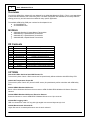
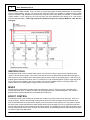
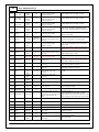
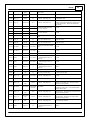
3512 - Mitsubishi EVO 9
C1-25
Crank Position
Sensor 1 Hall
Crank
Position
Sensor
43
10K pullup to 12V. Will work with
ground or f loating switches.
Frequency input only .
See Setup Wizard Cam/Crank page f or options.
C1-26
Cam Position
Sensor 1 Hall
Exh Cam
Position
Sensor
50
10K pullup to 12V. Will work with
ground or f loating switches.
Frequency input only .
See Setup Wizard Cam/Crank page f or options.
C1-27
Cam Position
Sensor 2 Hall
Int Cam
Position
Sensor
53
10K pullup to 12V. Will work with
ground or f loating switches.
Frequency input only .
See Setup Wizard Cam/Crank page f or options.
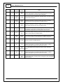
C1-28 Digital_In_3
Spare
Frequency
Input
Aux-6
10K pullup to 12V. Will work with
ground or f loating switches.
Frequency input only .
Can be used f or Flex Fuel or Turbo Speed or other
f requency input. See Setup Wizard to conf igure input.
C1-29 Digital_In_4
Vehicle Speed
Input
80
10K pullup to 12V. Will work with
ground or f loating switches.
Frequency input only .
See Setup Wizard Input Function Assignments page to
conf igure v ehicle speed.
C1-30 Digital_In_5
A/C Switch
C1-31 Digital_In_6
Spare
Frequency
Input
61
Not used
Not used
Clutch
Switch
88
Not used
Not used
C1-31
Coil 7
(Inf inity -8h Only )
C1-32 Digital_In_7
C1-32
Coil 8
(Inf inity -8h Only )
C1-33 Power Ground
Ground
10K pullup to 12V. Will work with
83 with 1K
ground or f loating switches. Switch
pulldown resistor
input only .
Conf igured in base session f or A/C Switch input.
10K pullup to 12V. Will work with
ground or f loating switches.
Frequency input only .
Can be used f or log OEM MAF signal or other spare
f requency input.
25 mA max source current
Not used. Spare Frequency input lost if using Inf inity 8h. MUST remov e pin f rom Inf inity 80 pin connector.
10K pullup to 12V. Will work with
ground or f loating switches. Switch
input only .
Conf igured in base session to activ ate Clutch Switch.
See Setup Wizard page f or options.
25 mA max source current
Not used. Idle A/C Of f set f unction lost if using Inf inity 8h. MUST remov e pin f rom Inf inity 80 pin connector.
AEMnet Ground Power ground
Four pin DTM connector in AEM adapter harness.
Contact AEM f or additional inf ormation.
C1-34 CAN A-
AEMNet CAN-
AEMNet
Dedicated high speed CAN
transceiv er
Four pin DTM connector in AEM adapter harness.
Contact AEM f or additional inf ormation.
C1-35 CAN A+
AEMNet CAN
+
AEMNet
Dedicated high speed CAN
transceiv er
Four pin DTM connector in AEM adapter harness.
Contact AEM f or additional inf ormation.
C1-36 CAN B-
Chassis
CANCAN-
No connect
Dedicated high speed CAN
transceiv er
Not used.
C1-37 CAN B+
Chassis
CAN+
No connect
Dedicated high speed CAN
transceiv er
Not used.
C1-38 Temp 1
Coolant Temp
Sensor
44
2.49k pullup to 5v
See Setup Wizard Coolant Temperature page f or options.
C1-39 Temp 2
Air Temp
Sensor
62 or Aux-7
2.49k pullup to 5v
See Setup Wizard Air Temperature page f or options.
C1-40 Temp 3
Spare Temp
Input
Aux 2
2.49k pullup to 5v
Can be used f or Oil Temperature input. See Setup
Wizard Oil Temperature page.
C1-41 LowsideSwitch_0
Fuel Pump
21
Lowside switch, 4A max, NO
internal f ly back diode. No pullup.
Switched ground. Will prime f or 2 seconds at key on
and activ ate if RPM > 0.
C1-42 LowsideSwitch_1
Boost Control
41
Lowside switch, 4A max with internal
See Setup Wizard Boost Control page f or options.
f ly back diode. Inductiv e load should
Monitor BoostControl [%] channel f or output state. Base
NOT hav e f ull time power. No
session conf igured to driv e stock boost control solenoid.
pullup.
C1-43 Power Ground
Ground
58
Power ground
Power ground.
C1-44 Knock Sensor 1
Knock Sensor
1
91
Dedicated knock signal processor
See Setup Wizard Knock Setup page f or options.
C1-45 Knock Sensor 2
Not used
No connect.
Dedicated knock signal processor
Not used.
Ground
C1-46 Power Ground
75
Power ground
Power ground.
Main Relay
C1-47
Control
Ground out to
main relay
57
0.7A max ground sink f or external
relay control
Will activ ate at key on and at key of f according to the
conf iguration settings.
C1-48 Ign Switch
Ignition Switch
99
10k pulldown
Full time battery power must be av ailable at C1-10
bef ore this input is triggered.
+5V Sensor
Power
42
Regulated, f used +5V supply f or
sensor power
Analog sensor power.
C1-49 +5V_Out
© 2015 AEM Performance Electronics