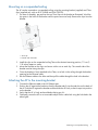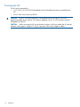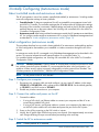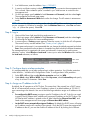
1
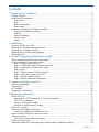
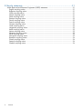
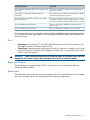
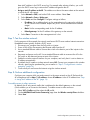
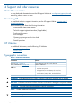
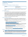
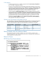
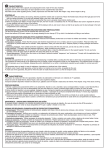
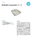
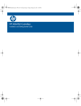
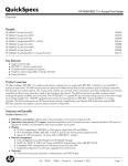
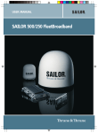
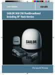
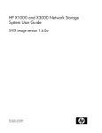
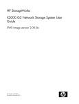
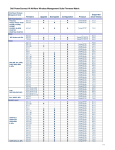
HP MSM410 802.11n AP Installation Guide
Abstract
This document describes how to install and initially configure the HP MSM410 802.11n Access Point (hereafter referred to as
the AP). This document applies to these MSM410 models: J9426A/B (USA), J9427A/B (WW), J9529A/B (JP), J9616A (IL).
Professional wireless and electrical equipment experience is required. The main configuration information for autonomous
mode is found in the MSM3xx / MSM4xx APs Configuration Guide. The main configuration information for controlled mode
is found in the MSM7xx Controllers Configuration Guide.
HP Part Number: 5998-3779
Published: March 2013
Edition: 1
© Copyright 2013 Hewlett-Packard Development Company, L.P.
The information contained herein is subject to change without notice. The only warranties for HP products and services are set forth in the express
warranty statements accompanying such products and services. Nothing herein should be construed as constituting an additional warranty. HP shall
not be liable for technical or editorial errors or omissions contained herein.
Acknowledgments
Microsoft®, and Windows® are U.S. registered trademarks of Microsoft Corporation.
Warranty
WARRANTY STATEMENT: See the warranty information sheet provided in the product box and available online.
Contents
1 Preparing for installation.............................................................................5
Package contents......................................................................................................................5
Identifying AP components.........................................................................................................5
Status lights.........................................................................................................................6
Ports...................................................................................................................................7
Radio and antenna..............................................................................................................7
Reset button........................................................................................................................7
Important information to read before installing..............................................................................8
Professional installation required............................................................................................8
Cabling..............................................................................................................................8
Plenum installation...............................................................................................................8
Country of use.....................................................................................................................8
Safety................................................................................................................................9
2 Installation...............................................................................................10
Mounting directly on a wall.....................................................................................................10
Mounting on a wall-mounted electrical box................................................................................10
Mounting on a suspended ceiling.............................................................................................11
Attaching the AP to the mounting bracket...................................................................................11
Powering the AP.....................................................................................................................12
3 Initially Configuring (Autonomous mode).....................................................13
About controlled mode and autonomous mode...........................................................................13
Initial configuration (autonomous mode)....................................................................................13
Step 1: Configure your computer..........................................................................................13
Step 2: Connect the cables and power on the AP...................................................................13
Step 3: Switch the AP to autonomous mode...........................................................................13
Step 4: Log in....................................................................................................................14
Step 5: Configure basic wireless protection...........................................................................14
Step 6: Assign an IP address to the AP.................................................................................14
Step 7: Test the wireless network..........................................................................................15
Step 8: Perform additional configuration...............................................................................15
4 Support and other resources......................................................................16
Online Documentation.............................................................................................................16
Contacting HP........................................................................................................................16
HP Websites..........................................................................................................................16
Typographic conventions.........................................................................................................16
A Regulatory information..............................................................................17
Notice for U.S.A.....................................................................................................................17
Manufacturer's FCC Declaration of Conformity statement........................................................17
FCC Class A statement.......................................................................................................17
Notice to professional installers............................................................................................17
Exposure to radio frequency energy.....................................................................................17
Notice for Canada.................................................................................................................18
Notice for the European Community..........................................................................................18
Countries of operation & conditions of use............................................................................18
Notice for Brazil, Aviso aos usuários no Brasil............................................................................19
Notice for Taiwan...................................................................................................................19
DGT LPD (Low Power Device) statement.................................................................................19
Turkish recycling notice............................................................................................................20
Vietnamese Information Technology and Communications compliance marking...............................20
Contents
3
B Recycle statements....................................................................................21
Waste Electrical and Electronic Equipment (WEEE) statements......................................................21
English recycling notice......................................................................................................21
Bulgarian recycling notice...................................................................................................21
Czech recycling notice........................................................................................................21
Danish recycling notice.......................................................................................................21
Dutch recycling notice.........................................................................................................21
Estonian recycling notice.....................................................................................................22
Finnish recycling notice.......................................................................................................22
French recycling notice.......................................................................................................22
German recycling notice.....................................................................................................22
Greek recycling notice........................................................................................................22
Hungarian recycling notice.................................................................................................22
Italian recycling notice........................................................................................................23
Latvian recycling notice.......................................................................................................23
Lithuanian recycling notice..................................................................................................23
Polish recycling notice.........................................................................................................23
Portuguese recycling notice.................................................................................................23
Romanian recycling notice..................................................................................................24
Slovak recycling notice.......................................................................................................24
Spanish recycling notice.....................................................................................................24
Swedish recycling notice.....................................................................................................24
4
Contents
1 Preparing for installation
The MSM410 is a Wi-Fi Alliance authorized Wi-Fi
CERTIFIED 802.11n/a/b/g product. The Wi-Fi CERTIFIED
Logo is a certification mark of the Wi-Fi Alliance
Package contents
•
The AP
•
One mounting bracket
•
Two mounting screws (4 mm x 25 mm (5/32 x 1 inch)) with wall anchors
•
Two T-bar clips with four nuts (only provided with rev B: US J9426B and WW J9427B)
•
Documentation
Identifying AP components
1
2
Front view
1: Status Lights (left to right) Power, Ethernet, Radio
2: Cable lock hole
Package contents
5
1
2
2
3
4
Back view
1: Cable channel
3: Ethernet port
2: Mounting bracket tab slot
4: Console port
Status lights
The status lights provide different information depending on whether the AP is operating in
autonomous mode or controlled mode. For more information on these modes, see “About controlled
mode and autonomous mode” (page 13).
Autonomous mode
In autonomous mode, the status lights indicate the following:
Light
State
Description
Power
Off
The AP has no power.
On
The AP is fully operational.
Blinking
The AP is starting up. If the Power light continues to blink after several minutes, it indicates
that the software failed to load. Reset or power cycle the AP. If this condition persists,
contact HP Support.
Off
The port is not connected or there is no activity.
Blinking
The port is transmitting or receiving data.
Blinking
The radio is transmitting or receiving data.
Ethernet
Radio
Controlled mode
During startup/discovery in controlled mode, the status lights indicate the following:
6
Status light behavior
Description
Power light blinks every two seconds.
The AP is starting up.
Power light blinks once per second.
The AP is looking for an IP address, or building the list of
VLANs on which to perform controller discovery. The
management tool is available until discovery occurs.
Preparing for installation
Status light behavior
Description
Power, Ethernet, and Radio, lights blink in sequence from
left to right.
The AP has obtained an IP address and is attempting to
discover a controller.
Power light is on. Ethernet and Radio lights blink
alternately.
The AP has found a controller and is attempting to establish
a secure management tunnel with it.
Power and Ethernet lights blink alternately and quickly.
Radio lights are off.
The AP has received a discovery reply from two or more
controllers with the same priority setting. The AP is unable
to connect with either controller until the conflict is resolved.
Power and Radio lights blink slowly.
The AP is attempting to establish a local mesh link to a
master node.
Power and Radio lights blink slowly.
The AP is attempting to establish wired connectivity.
Once the discovery process is complete, and the AP has established a secure management tunnel
to a controller, the Power light remains on and the Ethernet and Radio lights blink to indicate the
presence of traffic.
Ports
•
Ethernet port: Auto-sensing 10/100/1000 BaseT Ethernet port with an RJ-45 connector. The
port supports Power over Ethernet (PoE) 802.3af.
•
Console port: Standard console (serial) port with an RJ-45 connector. For details, see Console
Ports in the MSM3xx / MSM4xx APs Configuration Guide. There is no need to use the Console
port for initial configuration.
WARNING! Never connect the Console port to an Ethernet switch or PoE power source. This may
damage the AP. Connect it only to other serial ports via an RJ-45 to serial port adapter.
Radio and antenna
The AP contains an integrated single 802.11n/a/b/g radio with an internal three-element,
dual-band, MIMO antenna.
Reset button
The Reset button is accessible via a hole on the bottom of the AP as identified below. Insert a paper
clip under the cable and into the reset button hole at the precise angle shown.
Identifying AP components
7
1
1: Reset button hole
•
Press and quickly release the button to reset the AP.
•
To reset the AP to factory defaults, press the button until the status lights blink three times, then
release. Following a reset to factory defaults, the AP starts up in controlled mode with a an
option to switch it to autonomous mode.
Important information to read before installing
For indoor installation only.
Professional installation required
WARNING! Prior to installing or using the AP, consult with a professional installer trained in RF
installation and knowledgeable in local regulations including building and wiring codes, safety,
channel, power, indoor/outdoor restrictions, and license requirements for the intended country. It
is the responsibility of the end user to ensure that installation and use comply with local safety and
radio regulations.
Cabling
You must use the appropriate cables, and where applicable, surge protection, for your given
region. Cables with large boots may not insert into the RJ-45 connectors properly. It is recommended
that you do not use such cables. Cat 5e (or better) cabling is required.
Plenum installation
The AP can be installed in a plenum (UL2043 rating). The AP is suitable for use in environmental
air space in accordance with Section 300-22(C) of the National Electrical Code, and Sections
2-128, 12-010(3) and 12-100 of the Canadian Electrical Code, Part 1, CSA C22.1.
The AP should be installed in a similar orientation as in a ceiling installation. However, it is left to
a qualified installer to determine how to install and secure the AP in a plenum in an appropriate
and safe manner. Plenum-rated cables and attachment hardware must be used.
Country of use
CAUTION: In some regions, you are prompted to select the country of use during setup. Once
the country has been set, the AP will automatically limit the available wireless channels, ensuring
compliant operation in the selected country. Entering the incorrect country may result in illegal
operation and may cause harmful interference to other systems.
8
Preparing for installation
Safety
Take note of the following safety information during installation.
•
If your network covers an area served by more than one power distribution system, be sure
all safety grounds are securely interconnected.
•
Network cables may occasionally be subject to hazardous transient voltages (caused by
lightning or disturbances in the electrical power grid).
•
Handle exposed metal components of the network with caution.
•
The AP is powered-on when connected to a PoE power source.
•
The AP and all interconnected equipment must be installed indoors within the same building
including all PoE-powered network connections as described by Environment A of the IEEE
802.3af standard.
Important information to read before installing
9
2 Installation
The AP can be mounted on a wall, a wall-mounted electrical box, or a suspended ceiling. In all
cases, the first step is to mount the bracket, and the second step is to attach the AP to the bracket.
Mounting directly on a wall
1.
2.
3.
4.
5.
6.
7.
Respecting the UP indicator on the bracket, hold the bracket against the wall at the desired
position. Mark two holes for the screws (wall anchors) and one hole in the cutout area of the
bracket for the Ethernet cable.
Drill two holes for the wall anchors, typically 4.7 mm (3/16 inch) in diameter.
If necessary, drill a hole for the Ethernet cable in the marked cutout area of the bracket.
Alternatively, you can feed the Ethernet cable from above and through the AP cable channel.
Insert the anchors and tap them flush with the wall surface.
If applicable, pull the Ethernet cable through the hole in the wall and the hole in the bracket.
Screw the bracket to the wall.
Continue with “Attaching the AP to the mounting bracket” (page 11).
Mounting on a wall-mounted electrical box
The AP can be mounted on a wall-mounted electrical box using the supplied mounting bracket.
1. Disconnect power and take any other needed safety precautions.
1
2
1
3
1
2
1
1: Retention tabs
2: Mounting holes for electrical box
3: UP indicator
2.
3.
4.
5.
10
Installation
Remove the electrical box cover and any contents.
Pull the Ethernet cable down into the box and then through the hole in the bracket.
Hold the bracket against the box respecting the UP indicator and attach the bracket to the
box using appropriate countersunk screws.
Continue with “Attaching the AP to the mounting bracket” (page 11).
Mounting on a suspended ceiling
The AP can be mounted on a suspended ceiling using the mounting bracket (supplied) and T-bar
clips (supplied only with rev B US J9426B and WW J9427B).
1. For ease of assembly, pre-position the two T-bar clips on the bracket as illustrated. Work the
clip posts in the holes of the bracket until the posts can move freely. Remove the clips from the
bracket.
1
2
1
1: T-bar clip
2: Smooth side of bracket
2.
3.
4.
5.
Install the clips on the suspended ceiling T-bar at the desired mounting position, 7.9 cm (3
1/8 inches) apart on center.
Mount the bracket on the clips, and secure with a nut on each clip. The smooth side of the
bracket must be facing the clips.
Once the bracket is firmly attached to the T-bar, cut a hole in the ceiling through the bracket
opening for the Ethernet cable.
Run the Ethernet cable to the hole and then pull the cable through the hole in the bracket.
Attaching the AP to the mounting bracket
1.
2.
3.
4.
Connect the Ethernet cable to the AP Ethernet port.
Position the AP against the bracket so that the bracket tabs fit into the tab slots on the back of
the AP. Push the AP against the bracket and then slide the AP firmly so that it snaps into position
on the bracket.
Verify that the AP is firmly anchored before letting go of it.
Optionally, secure the AP to an immovable object with a cable lock using the hole below the
status lights.
Mounting on a suspended ceiling
11
Powering the AP
The AP can be powered by:
•
A 10/100 or 10/100/1000 PoE-enabled switch. PoE-enabled switches are available from
HP.
•
An HP 1-Port Power Injector (J9407A).
CAUTION: If the AP will be powered by a user-supplied PoE power injector, use only a
gigabit-compatible power injector. PoE injectors designed only for 10/100 networks are NOT
compatible with the AP.
CAUTION: When mounting the AP, ensure that the surface to which you attach the AP and the
fasteners used support a weight of 1.1 kg (2.4 pounds). Allow extra weight for cables.
12
Installation
3 Initially Configuring (Autonomous mode)
About controlled mode and autonomous mode
The AP can operate in one of two modes: controlled (the default) or autonomous. Switching modes
resets all configuration settings to factory defaults.
•
Controlled mode: To become operational, the AP must establish a management tunnel with
an MSM7xx Controller. The controller manages the AP and provides all configuration settings.
Discovery of the controller is automatic if default settings are used on the AP and the controller,
and both devices are on the same subnet. See Working with controlled APs in the MSM7xx
Controllers Configuration Guide.
•
Autonomous mode: After being switched to autonomous mode, the AP operates as a stand-alone
AP. You configure and manage an autonomous AP by using its Web-based management tool
as described in “Initial configuration (autonomous mode)” (page 13).
Initial configuration (autonomous mode)
This procedure describes how to switch a factory-default AP to autonomous mode and then perform
its initial configuration that enables you to establish a wireless connection through the AP to the
Internet.
In autonomous mode, the AP is managed via its Web-based management tool as described in this
section. This requires at least Microsoft Internet Explorer 8+ or Mozilla Firefox 3+.
For controlled mode configuration, see Working with controlled APs in the MSM7xx Controllers
Configuration Guide.
CAUTION: Wireless protection: A factory-default AP that has been switched to autonomous mode
has wireless protection options disabled. It is recommended that after initial configuration, you
enable a wireless security option to properly safeguard the wireless network from intruders. See
Wireless protection in the MSM3xx / MSM4xx APs Configuration Guide.
NOTE:
Do not power-on the AP until directed.
Step 1: Configure your computer
1.
2.
Disconnect your computer LAN port and configure it to use a static IP address in the range
192.168.1.2 to 192.168.1.254, and a subnet mask of 255.255.255.0. Set the default gateway
to 192.168.1.1, and DNS server to 192.168.1.1.
Disable any wireless connection on your computer.
Step 2: Connect the cables and power on the AP
1.
2.
3.
Connect the cables:
•
If using a PoE switch, use Ethernet cables to connect your computer and the AP to an
unused factory-default PoE switch.
•
If using a PoE injector, use Ethernet cables to connect your computer to the data-in port
on the PoE injector and the AP to the data and power-out port on the PoE injector.
Power on the AP by powering on the PoE switch or injector.
Initially, the AP power light will blink once every two seconds. Wait approximately one minute
until it begins blinking once per second before proceeding to the next step.
Step 3: Switch the AP to autonomous mode
NOTE:
A factory-default AP is assumed.
About controlled mode and autonomous mode
13
1.
2.
3.
4.
In a Web browser, enter the address: https://192.168.1.1.
A security certificate warning is displayed the first time you connect to the management tool.
This is normal. Select whatever option is needed in your Web browser to continue to the
management tool.
On the Login page, specify admin for both Username and Password, and then select Login.
The management tool home page opens.
Select Switch to Autonomous Mode and confirm the change. The AP restarts in autonomous
mode.
NOTE: To avoid a delay after switching modes, clear the ARP (address resolution protocol) cache
on your computer. In Windows for example, from the Windows Start menu, select Run and enter
"arp -d" (without the quotes). Select OK.
Step 4: Log in
1.
2.
3.
4.
5.
Wait until the Power light stops blinking and remains on.
On the Login page, specify admin for both Username and Password, and then select Login.
Click through the prompts for License and Registration.
In some regions, a Country prompt appears. Select the country in which the AP will operate.
The correct country must be selected. See “Country of use” (page 8).
At the password prompt it is recommended that you change the default password and select
Save. New passwords must be at least six characters long and include four different characters.
The management tool is organized with menus and sub-menus. Instructions for making menu
selections, such as "select Wireless > Local mesh" instruct you to select the Wireless menu and then
the Local mesh sub-menu, as follows:
Main menu
Sub-menu
Step 5: Configure basic wireless protection
It is recommended that you at least configure basic wireless protection. See Wireless protection
in the MSM3xx / MSM4xx APs Configuration Guide. To configure basic WPA protection:
1. Select VSC > HP and then enable Wireless protection and set it to WPA.
2. Under Mode, select WPA or WPA2, then under Key source, select Preshared key and specify
a key of at least 20 characters. Select Save.
Step 6: Assign an IP address to the AP
By default, the AP operates as a DHCP client. This means that if the network has a DHCP server,
the AP will automatically receive a new IP address in place of its default address of 192.168.1.1
upon connecting to the network. Use one of the following methods to assign an IP address to the
AP:
14
•
Pre-configure the DHCP server to assign a specific IP address to the AP. To do this you need
to specify the AP Ethernet MAC address and a reserved IP address on the DHCP server. The
AP Ethernet MAC address is printed on the AP label identified as Ethernet Base MAC, and
listed on the management tool Home page as Ethernet base MAC address.
•
Let the DHCP server automatically assign an IP address. By default, the DHCP server will assign
an IP address once the AP connects to the network. Once the DHCP server has assigned an
IP address to the AP, you can then find the IP address of the AP by looking for its Ethernet
Initially Configuring (Autonomous mode)
base MAC address in the DHCP server log. For example after sub-step 4 below, you could
go to the DHCP server log to retrieve the IP address assigned to the AP.
•
Assign a static IP address to the AP. The address must be on the same subnet as the network
to which the AP will connect.
1. Select Network > DNS, and set the DNS server address. Select Save.
2. Select Network > Ports > Bridge port.
3. Select Static and then Configure. Configure settings as follows:
4.
•
IP address: Set an address that is on the same subnet as the network to which the
AP will connect once installed. Respect any DHCP server-mandated static address
ranges.
•
Mask: Set the corresponding mask for the IP address.
•
Default gateway: Set the IP address of the gateway on the network.
Select Save. Connection to the management tool is lost.
Step 7: Test the wireless network
For the purposes of this example, the network must have a DHCP server and an Internet connection.
Broadband routers typically include a DHCP server.
1. Disconnect your computer from the PoE switch or injector.
2. Power off the AP by disconnecting the Ethernet cable from the AP.
3. Use a standard Ethernet cable to connect the switch or the data in port of the injector to the
network.
4. Reconnect and power on the AP. Use a standard Ethernet cable to reconnect the AP to the
PoE switch or the data and power-out port of the injector.
5. Enable the wireless network interface on your computer, and verify that it is set to obtain an
IP address automatically.
6. By default, the AP creates a wireless network named HP. Connect your computer to this wireless
network, specifying the preshared key you set earlier in “Step 5: Configure basic wireless
protection” (page 14).
7. Confirm that you can browse the Internet using the wireless network.
Step 8: Perform additional configuration
Configure your computer LAN port and connect it to the same network as the AP. Re-launch the
AP management tool at https://<IP address> where <IP address> is the AP IP address from “Step
6: Assign an IP address to the AP” (page 14).
To enable access to other resources
By default, the AP only permits traffic that is addressed to the default gateway on the network
(which enables you to connect to the Internet). To enable access to other resources:
1. Select VSC > Profiles and then select the HP profile.
2. On the Add/Edit Virtual Service Community page clear the Wireless security filters checkbox.
3. Select Save.
Initial configuration (autonomous mode)
15
4 Support and other resources
Online Documentation
You can download documentation from the HP Support Website at: www.hp.com/support/manuals.
Search by product number or name.
Contacting HP
For worldwide technical support information, see the HP support Website: www.hp.com/
networking/support
Before contacting HP, collect the following information:
•
Product model names and numbers
•
Technical support registration number (if applicable)
•
Product serial numbers
•
Error messages
•
Operating system type and revision level
•
Detailed questions
HP Websites
For additional information, see the following HP Websites:
•
www.hp.com/networking
•
www.hp.com
Typographic conventions
Table 1 Document conventions
Convention
Element
Blue text: Table 1 (page 16)
Cross-reference links and e-mail addresses
Blue, underlined text: www.hp.com
Website addresses
Bold text
• Keys that are pressed
• Text typed into a GUI element, such as a box
• GUI elements that are clicked or selected, such as menu
and list items, buttons, tabs, and check boxes
WARNING!
CAUTION:
IMPORTANT:
NOTE:
TIP:
16
Indicates that failure to follow directions could result in bodily harm or death.
Indicates that failure to follow directions could result in damage to equipment or data.
Provides clarifying information or specific instructions.
Provides additional information.
Provides helpful hints and shortcuts.
Support and other resources
A Regulatory information
Notice for U.S.A.
Manufacturer's FCC Declaration of Conformity statement
Manufacturer:
Hewlett-Packard Company
3000 Hanover Street
Palo Alto, CA 94304-1185 USA
For questions regarding this declaration, contact the Product Regulations Manager at the above
address.
FCC Class A statement
This is an FCC Class A device. In a domestic environment this product may cause radio interference
in which case the user may be required to take adequate measures. This equipment has been
tested and found to comply with the limits for a Class A digital device, pursuant to Part 15 of the
FCC Rules. These limits are designed to provide reasonable protection against harmful interference
when the equipment is operated in a commercial environment. This equipment generates, uses,
and can radiate radio frequency energy and, if not installed and used in accordance with the
instruction manual, may cause harmful interference to radio communications. Operation of this
equipment in a residential area is likely to cause harmful interference in which case the user will
be required to correct the interference at their own expense.
Notice to professional installers
As a Professional Installer responsible for the proper installation and configuration of this Access
Point, you need to understand and prepare for operating near any TDWR (Terminal Doppler
Weather Radar) locations. The FCC has requested that you become familiar with and comply with
the following:
•
Read and understand the FCC Memorandum dated July 27th, 2010, Subject: Elimination of
interference to Terminal Doppler Weather Radar (TDWR) located here:
www.spectrumbridge.com/Libraries/Misc_docs/
FCC_Memorandum_on_UNII_Device_Operartion.sflb.ashx
•
If the AP system is within the specified range 35km (21.75 mi) of any TDWR, set the primary
transmit frequency (and alternate frequencies, if used) to a frequency (or frequencies) at least
30 MHz (center-to-center) from the TDWR operation frequency shown on
www.spectrumbridge.com/udia/search.aspx, or in the table shown in the above FCC
Memorandum.
•
If you are using automatic channel assignment, add the channels you need to avoid in the
automatic channel exclusion list.
•
Register each AP system operating within 35km (21.75mi) of any TDWR in the voluntary
WISPA-sponsored database at: www.spectrumbridge.com/udia/home.aspx
Exposure to radio frequency energy
WARNING! Although the radiated output power of this device is below the FCC radio exposure
limits, the device should be used in such a manner that the potential for human contact with the
antennas during normal operation is minimized. To avoid the possibility of exceeding the FCC
radio frequency exposure limits, human proximity to the antennas should not be less than 20 cm
(8 inches) during normal operation.
Notice for U.S.A.
17
Notice for Canada
The following notices apply to Canada:
•
This device complies with the limits for a Class B digital device and conforms to Industry
Canada standard ICES-003. Products that contain a radio transmitter comply with Industry
Canada standard RSS210 and are labeled with an IC approval number.
•
Cet appareil numérique de la classe B est conforme à la norme ICES-003 de Industry Canada.
La radio sans fil de ce dispsitif est conforme à la certification RSS 210 de Industry Canada
et est étiquetée avec un numéro d'approbation IC.
•
This device complies with the Class B limits of Industry Canada. Operation is subject to the
following two conditions: 1) this device may not cause harmful interference, and 2) this device
must accept interference received, including interference that may cause undesired operation.
To reduce potential radio interference with other users, the antenna type and its gain should be
so chosen that the equivalent isotropically radiated power (EIRP) is not more than that required for
successful communication.
Notice for the European Community
This device complies with the EMC Directive 2004/108/EC, Low Voltage Directive 2006/95/EC
and R&TTE Directive 1999/5/EC. Compliance with these directives implies conformity to
harmonized European standards (European Norms) that are listed on the EU Declaration of
Conformity that has been issued by HP for this device.
Countries of operation & conditions of use
This device may be used in the following EU and EFTA countries: Austria, Belgium, Bulgaria,
Cyprus, Czech Republic, Denmark, Estonia, Finland, France, Germany, Greece, Hungary, Iceland,
Ireland, Italy, Latvia, Liechtenstein, Lithuania, Luxembourg, Malta, Netherlands, Norway, Poland,
Portugal, Romania, Slovakia, Slovenia, Spain, Sweden, Switzerland and the United Kingdom.
Requirements for outdoor vs. indoor operation, licensing and allowed channels of operation apply
in some countries as described below.
NOTE: The user must use the configuration utility provided with this device to ensure the channels
of operation are in conformance with the spectrum usage rules for EU and EFTA countries as
described below.
2.4 GHz operation
18
•
This device may be operated outdoors or indoors in all EU and EFTA countries using the 2.4
GHz band (Channels 1 - 13), except where noted below.
•
In France, this device may use the entire 2400 - 2483.5 MHz band (Channels 1 through 13)
for indoor applications. For outdoor use, only the 2400 - 2454 MHz frequency band (Channels
1 through 9) may be used. For the latest requirements, see http://www.art-telecom.fr.
L'utilisation de cet equipement (2.4 GHz wireless LAN) est soumise à certaines restrictions:
cet equipement peut être utilisé à l'interieur d'un batiment en utilisant toutes les frequences de
2400 a 2483.5 MHz (Chaine 1-13). Pour une utilisation en environnement exterieur, vous
devez utiliser les frequencies comprises entre 2400 a 2454-MHz (Chaine 1-9). Pour les
dernières restrictions, voir http://www.art-telecom.fr.
Regulatory information
5 GHz operation
•
This device requires the user or installer to properly enter the current country of operation in
the 5 GHz Radio Configuration Window.
•
This device will automatically limit the allowable channels determined by the current country
of operation. Incorrectly entering the country of operation may result in illegal operation and
may cause harmful interference to other systems. The user is obligated to ensure the device is
operating according to the channel limitations, outdoor/indoor restrictions and license
requirements for each European Community country as described in this guide.
•
This device employs a radar detection feature required for European Community and EFTA
country operation in the 5 GHz band. This feature is automatically enabled when the country
of operation is correctly configured for any European Community or EFTA country. The presence
of nearby radar operation may result in temporary interruption of operation of this device.
The radar detection feature will automatically restart operation on a channel free of radar.
•
This device is restricted to indoor use when operated in EU and EFTA countries using the
5.15-5.35 GHz band (Channels 36, 40, 44, 48, 52, 56, 60 and 64). See the table below
for the allowed 5 GHz channels in each band.
Operation using 5 GHz channels in the European Community
The user/installer must use the provided configuration utility to check the current channel of operation
and make necessary configuration changes to ensure operation occurs in conformance with
European National spectrum usage laws as described below and elsewhere in this guide.
Frequency Band (MHz)
Allowed Channels
Usage
Maximum EIRP (mW)
5150 - 5250
36, 40, 44, 48
Indoor use only
200
5250 - 5350
52, 56, 60, 64
Indoor use only
200
5470 - 5725
100, 104, 108, 112, 116,
132, 136, 140.
Indoor or outdoor use
1000
Notice for Brazil, Aviso aos usuários no Brasil
Este equipamento opera em caráter secundário, isto é, não tem direito à proteção contra
interferência prejudicial, mesmo de estações do mesmo tipo, e não pode causar interferência a
sistemas operando em caráter primário.
Notice for Taiwan
DGT LPD (Low Power Device) statement
Notice for Brazil, Aviso aos usuários no Brasil
19
Turkish recycling notice
Türkiye Cumhuriyeti: EEE Yönetmeliğine Uygundur
Vietnamese Information Technology and Communications compliance
marking
20
Regulatory information
B Recycle statements
Waste Electrical and Electronic Equipment (WEEE) statements
English recycling notice
Disposal of waste equipment by users in private household in the European Union
This symbol means do not dispose of your product with your other household waste. Instead, you should
protect human health and the environment by handing over your waste equipment to a designated
collection point for the recycling of waste electrical and electronic equipment. For more information,
please contact your household waste disposal service
Bulgarian recycling notice
Изхвърляне на отпадъчно оборудване от потребители в частни домакинства в Европейския
съюз
Този символ върху продукта или опаковката му показва, че продуктът не трябва да се изхвърля заедно
с другите битови отпадъци. Вместо това, трябва да предпазите човешкото здраве и околната среда,
като предадете отпадъчното оборудване в предназначен за събирането му пункт за рециклиране на
неизползваемо електрическо и електронно борудване. За допълнителна информация се свържете с
фирмата по чистота, чиито услуги използвате.
Czech recycling notice
Likvidace zařízení v domácnostech v Evropské unii
Tento symbol znamená, že nesmíte tento produkt likvidovat spolu s jiným domovním odpadem. Místo
toho byste měli chránit lidské zdraví a životní prostředí tím, že jej předáte na k tomu určené sběrné
pracoviště, kde se zabývají recyklací elektrického a elektronického vybavení. Pro více informací kontaktujte
společnost zabývající se sběrem a svozem domovního odpadu.
Danish recycling notice
Bortskaffelse af brugt udstyr hos brugere i private hjem i EU
Dette symbol betyder, at produktet ikke må bortskaffes sammen med andet husholdningsaffald. Du skal
i stedet den menneskelige sundhed og miljøet ved at afl evere dit brugte udstyr på et dertil beregnet
indsamlingssted for af brugt, elektrisk og elektronisk udstyr. Kontakt nærmeste renovationsafdeling for
yderligere oplysninger.
Dutch recycling notice
Inzameling van afgedankte apparatuur van particuliere huishoudens in de Europese Unie
Dit symbool betekent dat het product niet mag worden gedeponeerd bij het overige huishoudelijke afval.
Bescherm de gezondheid en het milieu door afgedankte apparatuur in te leveren bij een hiervoor bestemd
inzamelpunt voor recycling van afgedankte elektrische en elektronische apparatuur. Neem voor meer
informatie contact op met uw gemeentereinigingsdienst.
Waste Electrical and Electronic Equipment (WEEE) statements
21
Estonian recycling notice
Äravisatavate seadmete likvideerimine Euroopa Liidu eramajapidamistes
See märk näitab, et seadet ei tohi visata olmeprügi hulka. Inimeste tervise ja keskkonna säästmise nimel
tuleb äravisatav toode tuua elektriliste ja elektrooniliste seadmete käitlemisega egelevasse kogumispunkti.
Küsimuste korral pöörduge kohaliku prügikäitlusettevõtte poole.
Finnish recycling notice
Kotitalousjätteiden hävittäminen Euroopan unionin alueella
Tämä symboli merkitsee, että laitetta ei saa hävittää muiden kotitalousjätteiden mukana. Sen sijaan sinun
on suojattava ihmisten terveyttä ja ympäristöä toimittamalla käytöstä poistettu laite sähkö- tai
elektroniikkajätteen kierrätyspisteeseen. Lisätietoja sat jätehuoltoyhtiöltä.
French recycling notice
Mise au rebut d'équipement par les utilisateurs privés dans l'Union Européenne
Ce symbole indique que vous ne devez pas jeter votre produit avec les ordures ménagères. Il est de
votre responsabilité de protéger la santé et l'environnement et de vous débarrasser de votre équipement
en le remettant à une déchetterie effectuant le recyclage des équipements électriques et électroniques.
Pour de plus amples informations, prenez contact avec votre service d'élimination des ordures ménagères.
German recycling notice
Entsorgung von Altgeräten von Benutzern in privaten Haushalten in der EU
Dieses Symbol besagt, dass dieses Produkt nicht mit dem Haushaltsmüll entsorgt werden darf. Zum
Schutze der Gesundheit und der Umwelt sollten Sie stattdessen Ihre Altgeräte zur Entsorgung einer dafür
vorgesehenen Recyclingstelle für elektrische und elektronische Geräte übergeben. Weitere Informationen
erhalten Sie von Ihrem Entsorgungsunternehmen für Hausmüll.
Greek recycling notice
Απόρριψη άχρηοτου εξοπλισμού από ιδιώτες χρήστες στην Ευρωπαϊκή Ένωση
Αυτό το σύμβολο σημαίνει ότι δεν πρέπει να απορρίψετε το προϊόν με τα λοιπά οικιακά απορρίμματα.
Αντίθετα, πρέπει να προστατέψετε την ανθρώπινη υγεία και το περιβάλλον παραδίδοντας τον άχρηστο
εξοπλισμό σας σε εξουσιοδοτημένο σημείο συλλογής για την ανακύκλωση άχρηστου ηλεκτρικού και
ηλεκτρονικού εξοπλισμού. Για περισσότερες πληροφορίες, επικοινωνήστε με την υπηρεσία απόρριψης
απορριμμάτων της περιοχής σας.
Hungarian recycling notice
A hulladék anyagok megsemmisítése az Európai Unió háztartásaiban
Ez a szimbólum azt jelzi, hogy a készüléket nem szabad a háztartási hulladékkal együtt kidobni. Ehelyett
a leselejtezett berendezéseknek az elektromos vagy elektronikus hulladék átvételére kijelölt helyen történő
beszolgáltatásával megóvja az emberi egészséget és a környezetet.További információt a helyi
köztisztasági vállalattól kaphat.
22
Recycle statements
Italian recycling notice
Smaltimento di apparecchiature usate da parte di utenti privati nell'Unione Europea
Questo simbolo avvisa di non smaltire il prodotto con i normali rifi uti domestici. Rispettare la salute
umana e l'ambiente conferendo l'apparecchiatura dismessa a un centro di raccolta designato per il
riciclo di apparecchiature elettroniche ed elettriche. Per ulteriori informazioni, rivolgersi al servizio per
lo smaltimento dei rifi uti domestici.
Latvian recycling notice
Europos Sąjungos namų ūkio vartotojų įrangos atliekų šalinimas
Šis simbolis nurodo, kad gaminio negalima išmesti kartu su kitomis buitinėmis atliekomis. Kad
apsaugotumėte žmonių sveikatą ir aplinką, pasenusią nenaudojamą įrangą turite nuvežti į elektrinių ir
elektroninių atliekų surinkimo punktą. Daugiau informacijos teiraukitės buitinių atliekų surinkimo tarnybos.
Lithuanian recycling notice
Nolietotu iekārtu iznīcināšanas noteikumi lietotājiem Eiropas Savienības privātajās mājsaimniecībās
Šis simbols norāda, ka ierīci nedrīkst utilizēt kopā ar citiem mājsaimniecības atkritumiem. Jums jārūpējas
par cilvēku veselības un vides aizsardzību, nododot lietoto aprīkojumu otrreizējai pārstrādei īpašā lietotu
elektrisko un elektronisko ierīču savākšanas punktā. Lai iegūtu plašāku informāciju, lūdzu, sazinieties ar
savu mājsaimniecības atkritumu likvidēšanas dienestu.
Polish recycling notice
Utylizacja zużytego sprzętu przez użytkowników w prywatnych gospodarstwach domowych w
krajach Unii Europejskiej
Ten symbol oznacza, że nie wolno wyrzucać produktu wraz z innymi domowymi odpadkami.
Obowiązkiem użytkownika jest ochrona zdrowa ludzkiego i środowiska przez przekazanie zużytego
sprzętu do wyznaczonego punktu zajmującego się recyklingiem odpadów powstałych ze sprzętu
elektrycznego i elektronicznego. Więcej informacji można uzyskać od lokalnej firmy zajmującej wywozem
nieczystości.
Portuguese recycling notice
Descarte de equipamentos usados por utilizadores domésticos na União Europeia
Este símbolo indica que não deve descartar o seu produto juntamente com os outros lixos domiciliares.
Ao invés disso, deve proteger a saúde humana e o meio ambiente levando o seu equipamento para
descarte em um ponto de recolha destinado à reciclagem de resíduos de equipamentos eléctricos e
electrónicos. Para obter mais informações, contacte o seu serviço de tratamento de resíduos domésticos.
Waste Electrical and Electronic Equipment (WEEE) statements
23
Romanian recycling notice
Casarea echipamentului uzat de către utilizatorii casnici din Uniunea Europeană
Acest simbol înseamnă să nu se arunce produsul cu alte deşeuri menajere. În schimb, trebuie să protejaţi
sănătatea umană şi mediul predând echipamentul uzat la un punct de colectare desemnat pentru reciclarea
echipamentelor electrice şi electronice uzate. Pentru informaţii suplimentare, vă rugăm să contactaţi
serviciul de eliminare a deşeurilor menajere local.
Slovak recycling notice
Likvidácia vyradených zariadení používateľmi v domácnostiach v Európskej únii
Tento symbol znamená, že tento produkt sa nemá likvidovať s ostatným domovým odpadom. Namiesto
toho by ste mali chrániť ľudské zdravie a životné prostredie odovzdaním odpadového zariadenia na
zbernom mieste, ktoré je určené na recykláciu odpadových elektrických a elektronických zariadení.
Ďalšie informácie získate od spoločnosti zaoberajúcej sa likvidáciou domového odpadu.
Spanish recycling notice
Eliminación de los equipos que ya no se utilizan en entornos domésticos de la Unión Europea
Este símbolo indica que este producto no debe eliminarse con los residuos domésticos. En lugar de ello,
debe evitar causar daños a la salud de las personas y al medio ambiente llevando los equipos que no
utilice a un punto de recogida designado para el reciclaje de equipos eléctricos y electrónicos que ya
no se utilizan. Para obtener más información, póngase en contacto con el servicio de recogida de
residuos domésticos.
Swedish recycling notice
Hantering av elektroniskt avfall för hemanvändare inom EU
Den här symbolen innebär att du inte ska kasta din produkt i hushållsavfallet. Värna i stället om natur
och miljö genom att lämna in uttjänt utrustning på anvisad insamlingsplats. Allt elektriskt och elektroniskt
avfall går sedan vidare till återvinning. Kontakta ditt återvinningsföretag för mer information.
24
Recycle statements