1
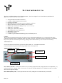
TL2 Instructions for Use
The TL2 is an affordable high precision digital thermometer. It has been designed for use in both laboratory and industrial
applications. Features of the TL2 are as follows:
•
•
•
•
•
•
•
•
•
•
•
•
Configurable RTD and SPRT combinations
Available 2 channel temperature measurement
0.001 degree resolution
Implements ITS-90 or Callendar-Van Dusen calibration coefficients
Displays temperature in Celsius, Fahrenheit, Kelvin or Ohms
Backlit, Large LCD character display (Backlight AC powered unit only)
USB Type ‘A’ PC interface
USB Type ‘B’ flash memory interface
User programmable relay output interface
Detachable AC power cord
IP50 enclosure rating
Available as a portable model with battery power (with limited features)
Cautions
The TL2 and associated temperature probes are sensitive devices and should be handled with care. Care should be taken not to
submit the temperature probes to mechanical shock, over-heating or exposure to fluids at the probe to cable interface. Overheating
the probes beyond their calibrated temperature range, damage and/or contamination may cause sensor drift and instability.
Authorized Service
Service and Calibration should only be performed by ThermoProbe, Inc. or an authorized distributor.
Contact ThermoProbe for questions about setting up this software or using the TL2.
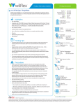
USER INTERFACE FRONT
Up Button
Select Button
Power Button
Channel Indicators
Down Button
Power Button (AC Unit) – Use the power button to save your settings (temperature units, display decimals, zero adjustments, etc.),
and to place the TL2 in ‘Standby’ mode. If you remove AC the power without putting the TL2 in Standby mode, the user settings
will revert to the previous settings.
Power Button (Battery Unit) – Used to power the unit On or Off. (Settings are saved when the unit is powered off.)
1
02/2013, JK
Select Button - Activates the user settings menu and selects menu items.
Up and Down Buttons - Selects the display for channel 1 and channel 2, navigates the menu (display next/previous menu item).
Also, adjusts the zero correction when in the Zero Adjust Mode.
Channel Indication – Marker indicates which channel is currently being displayed. (For active display and menu functions)
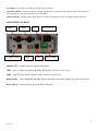
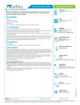
USER INTERFACE REAR
Channel 1
AC power socket
Channel 2
USB1
Fuse
USB2
On/Off Switch
Relay header
Channel 1 &2 – Female sockets for probe connections.
USB1 - type ‘A’ socket for connecting flash USB devices (AC powered units only)
USB2 – type ‘B’ socket for PC interface cable (AC powered units only)
Relay Header – User configurable normally open or normally closed relay control (AC powered units only)
Power Switch – Used to turn AC powered units On and Off
2
02/2013, JK
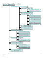
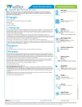
Interface Menu: (AC Powered Unit)
SELECT
rECord – Data logging setup & control
FLASH
StArt/StoP
donE - Select to Exit Menu
PC
rAtE
1 sec
10 sec
30 sec
60 sec
1 hr
PoLL
donE - Select to Exit Menu
HASH on – Enables Checksum
HASHoFF– Disables Checksum
donE - Select to Exit Menu
UnItS
C (Celsius)
F (Fahrenheit)
AbS (Kelvin)
o (Ohms)
dEC
Hds(Hundredths)
tHoU(Thousandths)
L-A-H – Displays Low, Average & High readings
rELAY
EnAbLe/dISAbLE
SEt
donE - Select to Exit Menu
Corr - Displays Zero Correction
donE - Select to Exit Menu
3
02/2013, JK
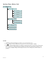
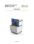
Interface Menu: (Battery Unit)
SELECT
UnItS
C (Celsius)
F (Fahrenheit)
AbS (Kelvin)
o (Ohms)
dEC
Hds(Hundredths)
tHoU(Thousandths)
L-A-H – Displays Low, Average
& High readings
Corr - Displays Zero Correction
donE - Select to Exit Menu
NOTES:
•
•
•
All displayed values and changes are for the current selected channel only.
To save settings, the Power Button must be pressed. This will set the unit to ‘Standby’.
The low, average and high readings are cumulative from the time the TL2 is powered on. They are not
saved when the TL2 is shut down or put in standby and will re-start when the unit is turned on. The
low, average, and high readings will be displayed once the TL2's readings have stabilized (about 22
seconds.)
4
02/2013, JK
USB Flash Drive Logging (AC powered unit only):
1.
2.
3.
4.
5.
Insert a flash drive into the USB1 type ‘A’ socket on the back of the TL2.
From the record menu, select ‘FLASH’ and ‘StArt’.
The TL2 display will flash ‘ACCESS’ until the flash drive recording has started. (A ‘no DSC’ message will appear if the
flash drive is not detected).
The up/down arrow indicator will blink on the LCD display to indicate that logging is in process.
To stop the data logging, select ‘FL StoP’ from the menu. Wait for the ‘FL DonE’ message to display before removing the
flash drive from the TL2. (If the drive is removed before the logging has been stopped, the data will be lost.)
Once the flash drive data logging has been completed, the data can be opened on a standard PC.
Note: Each time the TL2 records to the flash drive it will create a new file numbered sequentially higher than the previous file. (ex:
0001.csv, 0002.csv, etc.)
1.
2.
3.
4.
5.
Remove the flash drive from the TL2.
Insert the flash drive into a USB port on the PC.
Browse to the folder containing the flash drive contents.
The TL2 data will be contained in a .csv file that can be opened with either Microsoft Excel or a text editor such as Notepad.
The column format is as follows: Date, Time, Channel 1 reading, Channel 1 units, Channel 2 reading and Channel 2 units.
Polling Mode (AC powered unit only):
You can set the TL2 to send data on command. This is useful for people who write data collection software that will request data
only when it is needed. To place the TL2 in polling mode, select “POLL” as the sample rate to be used under the recording section of
the TL2 menu. (See Interface Menu Diagram) When the PC sends a question mark character (?) to the TL2, the TL2 will respond
with the temperature. When the TL2 is set to flash record mode, the polling feature will not work.
5
02/2013, JK
Temperature controlled Relay (AC powered unit only):
The TL2 comes equipped with a switchable relay. This relay will toggle whenever the temperature crosses the set point threshold set
through the user menu. The provided screw-terminal header can be wired in two configurations:
•
•
Terminals 1-2 are normally closed (NC) and will turn OFF (open) when the relay is set.
Terminals 1-3 are normally open (NO) and will turn ON (close) when the relay is set.
Figure 1: Relay screw-terminal header
The relay function can be implemented from the user menu. For the relay function to be active, the user must select ‘EnAbLE’ from
the relay menu. Also from the relay menu, the temperature set point can be configured. (‘rELAY’ -> ‘SEt’) Use the Up & Down
buttons to select the desired setpoint. Ensure this setpoint is correct before selecting the ‘EnAbLE’ function. The relay set point will
remain the same regardless of the unit selection (C, F or K).
Once the relay has been toggled, it will remain in that state until the user disables it using the Select button. If desired, the user will
then need to re-enable the relay from the user menu.
Zero Correction
Over time, a sensor may experience a shift in temperature at different ranges of the instrument. Zero correction allows the user to
make an adjustment to the current channel temperature display that effectively corrects for this shift. This offset or ‘zero correction’
is applied to the entire effective range of the instrument. Each channel has its own zero correction.
NOTE: A zero correction made at a particular point may not correct the temperature at another point. It is recommended that the
instrument be fully calibrated annually to maintain acceptable temperature tolerances for the range of the instrument.
To view the zero correction for the current channel, select the “Corr” option from the menu.
To set a zero correction:
1. Use the function and arrow buttons to navigate to the “Corr” item in the menu. Press and hold the power button. While holding the
power button, press the function button until the "Adj" menu item appears. Release both buttons.
2. Press and release the function button again. The double arrows will flash indicating that you are in zero correction mode. Use the
up and down arrows to adjust the display temperature as desired. The adjustment will only apply to the channel on the display.
3. When you've adjusted the display, press and release the function button. Use the arrow buttons and the function button to save or
cancel the zero correction and exit zero correction mode.
4. To view the zero correction, use the function button and arrow buttons to navigate to the Corr menu item as before. This time,
press and release the function button. The display will show the zero correction for the selected channel and then return to
temperature display mode.
5. To save the zero correction, the Power Button must be pressed. This will set the unit to ‘Standby’.
6
02/2013, JK
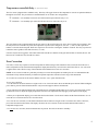
PC Software setup:
There is a PC driver file that is needed to connect the TL2 to your PC. We have included a CD with the driver
software for Windows XP, Windows Server 2003, Windows Vista, Windows Server 2008, Windows 7,
Windows Server 2008 R2. Other operating systems are supported and driver software is available. Contact
ThermoProbe to request the appropriate drivers for your system.
Use the Windows Add Hardware Wizard and the driver files to set up a USB Com port to connect to the TL2.
Connect using HyperTerminal or other software that can connect interface with the selected Com port.
** The USB driver software web site is (http://www.ftdichip.com/Drivers/VCP.htm)
.Note These instructions are taken from a document that is available online from Future Technology Devices International.
(http://www.ftdichip.com/Support/Documents/AppNotes/AN_104_FTDI_Drivers_Installation_Guide_for_WindowsXP%28FT_000093%29
.pdf). Detailed technical information is available from that website. Technical assistance with installing the driver software is available from
ThermoProbe, Inc. Check http://thermoprobe.net/docs/index.html for the latest version of this document.
Instructions to install the TL2 PC driver (Windows XP shown) The driver for the TL2 PC (Future Technology Devices International
driver) installs a Virtual Com Port (VCP) on your PC. The steps to install this driver are:
1.
2.
3.
4.
5.
6.
7.
Place the CD provided with your TL2 in the CD drive of the PC.
Connect the TL2 to the PC with the provided USB cable.
Make sure the TL2 is plugged into the wall with the AC power cord.
Make sure the TL2 is powered on.
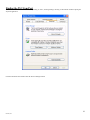
A Found New Hardware Wizard window should appear.
Select "No, not this time".
Click "Next >".
7
02/2013, JK
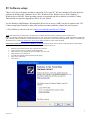
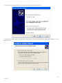
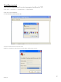
8. On the next screen click "Install from a list or specific location (Advanced)" and click "Next >".
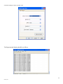
9. On the next screen select "Search for the best driver in these locations.", Check the "Search removable media (floppy, CD-ROM…):", and
then click "Next”.
8
02/2013, JK
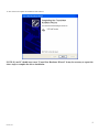
10. The wizard will complete the installation of the software.
NOTE: If your PC should start a new "Found New Hardware Wizard" it may be necessary to repeat the
above steps to complete the driver installation.
9
02/2013, JK
Using Hyperterminal:
You can use Hyperterminal to receive temperature data from the TL2.
Click "start" -> "Accessories" -> "Communications" -> "HyperTerminal"
Click "File"->"New Connection"
Give the connection a name and click "OK"
Select the Com Port for the TL2 and click "OK"
NOTE: See ‘Finding Com Port Section’ if you don’t know which com port to select.
10
02/2013, JK
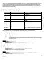
Set the Port Settings as shown and click "OK".
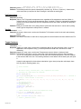
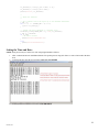
The Hyperterminal display should be as follows:
11
02/2013, JK
The TL2 will output the temperature for both channels. There are 3 columns in the interface display. The first
column is a date and timestamp. The second column is the first channel output and the third column is the
second channel output. The displayed units are the units selected from the faceplate (F, C, K or Ohms). The
displayed precision is four decimals.
TL2 HyperTerminal Command Set:
Function
Command
Description
Toggle Prompt (on) <cr>
Stop sending temperatures, show a ">", and wait
for a command.
Toggle Prompt (off) <cr>
Resume sending temperatures.
Set Date
D YY-MM-DD<cr>
Set the TL2's real time clock's date.
Set Time
T HH:MM:SS<cr>
Set the TL2's real time clock's time.
Set Rate
R [0,1,10,30,60,3600,poll]<cr> Set the rate the TL2 sends temperatures (in
seconds).
Poll Temperature
?<cr>
Send a temperature now.
Toggle Checksum
(on)
C<cr>
Add a checksum hash to the temperature.
Toggle Checksum
(off)
C<cr>
Don't send a checksum hash with the
temperature.
Send Version
V<cr>
Show the firmware version for the TL2 (there are 2
boards and each has a firmware version).
Note 1: The carriage return, <cr>, is hex digit 0x0D. The line feed (new line), <lf>, is hex digit 0x0A.
Note 2: All input commands are echoed back to the sender.
Toggle Prompt
Command: <cr>
Response (toggle on): <cr><lf>>
Response (toggle off): <cr><lf>
Remarks: No temperatures are sent while prompt mode is on. Temperature sending will resume once the
prompt is toggled off. If other functions are used while the prompt is on, the responses are preceded
by a prompt <cr><lf>>.
Set Date
Command: D YY-MM-DD<cr>
Response (success): New Date is: YYYY-MM-DD<cr><lf>
Response (failure): Error – use format "> D(ate) (YY)YY-MM-DD"<cr><lf>
Remarks: A lower case "d" or the word "Date" can be used.
Set Time
Command: T HH:MM:SS<cr>
Response (success): New Time is: HH:MM:SS<cr><lf>
Response (failure): Error – use format "> T(ime) HH:MM:SS"<cr><lf>
Remarks: A lower case "t" or the word "Time" can be used.
Set Rate
Command: R [0,1,30,60,3600,poll]<cr> (e.g. R 1<cr>, R 30<cr>, r poll<cr>
Response (success): Send Rate: X sec.<cr><lf>
12
02/2013, JK
Send Rate: Poll (enter ? For a temp.)<cr><lf>
Response (failure): Rate Format">R X" (X =1,10,30,60,3600,Poll)<cr><lf>.
Remarks: The brackets contain the options, separated by commas. (e.g. R 10<cr>, R poll<cr>). A lower case r
or the word Rate (or rate) can be used. Entering 0 is the same as entering poll.
Poll Temperature
Command: ?<cr>
Response (success):
Response (failure): The TL2 sends the temperature now, regardless of the temperature send rate. (When in
polling mode, the TL2 only sends temperatures when it is polled.) Polling for a temperature resets the
timer for the 10-3600 second rate (the next temperature will be sent <rate> seconds from the polled
temperature.
Remarks: Polling can be used when not in polling mode to synchronize the send rate. It can be used in polling
mode to get the temperature exactly when it is needed.
Version
Command: V<cr>
Response (success): A lower case v can be used. Sends the TL2 firmware version for the main and accessory
boards.
Response (failure): none
Remarks: The version information is useful when verifying that the correct firmware has been loaded on the TL2.
Toggle Checksum
Command: C<cr>
Response (toggle on): Lower case c can be used. A checksum hash of all bytes (exclusive of the <cr><lf>) is
appended to the temperature string. (a comma precedes the hash and is included in the hash
calculation)
Response (toggle off): Lower case c can be used. Temperatures are sent without a checksum hash.
Remarks: The checksum calculation is a sum of the bytes of the character string except for the terminating
<cr><lf>. All of the bytes are summed in an 8 bit value with overflow bits ignored. Then one is added
to the exclusive OR of the sum. The resulting checksum, when added to all the other bytes, will equal
0.
A sample code segment for the checksum calculation is given here (to keep the code simple, there
isn't any code for checking inputs, etc.):
//
// create checksum
//
// The entire string, including date, time, temperature and commas
// (including the comma before the checksum)
//
#define STRING_LEN 42
char sz_string[STRING_LEN + 1] = "2012-09-11,14:00:21,24.3254,C,24.2996,C,1C"; // checksum is
1C
// String to convert decimal to ascii hex
char hex[16] = {'0', '1', '2', '3', '4', '5', '6', '7', '8', '9', 'A', 'B', 'C', 'D', 'E',
'F'};
// The checksum string
char sz_checksum[3] = "\0";
// The checksum value
unsigned char c_sum = 0;
unsigned int c_checksum = 0;
int i = 0;
// compute checksum for the date/time/temperature string
for (i = 0; i < (STRING_LEN - 2); i++){
c_sum += (unsigned char)sz_string[i];
}
c_sum = (unsigned char)((c_sum ^ 0xFF) + 1);
// convert c_checksum to ascii
13
02/2013, JK
sz_checksum[0] = hex[((c_sum & 0xF0) >> 4)];
sz_checksum[1] = hex[(c_sum & 0x0F)];
printf("%s\r\n", sz_checksum);
//
// check the checksum
//
// get a numeric sum of the bytes up to the checksum characters
c_sum = 0;
for (i = 0; i < (STRING_LEN - 2); i++){
c_sum += sz_string[i];
}
// convert the ascii checksum to a decimal value
sscanf(&sz_string[STRING_LEN - 2], "%x", &c_checksum);
c_sum += c_checksum;
if (c_sum){
// an error occured
printf("Invalid Checksum\r\n");
}
else{
printf("Valid Checksum\r\n");
}
Setting the Time and Date:
NOTE: It may be necessary to set the TL2 clock using Hyperterminal as follows:
1.
2.
After a connection has been established with the TL2 per the previous steps, hit ‘Enter’ to create a line break in the data
feed.
To change the date enter the text as follows: Date (YY)YY-MM-DD
3.
To change the time enter the text as follows: Time HH:MM:SS
14
02/2013, JK
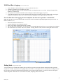
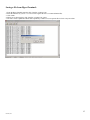
Saving a file from HyperTerminal:
1. From the HyperTerminal menu bar click "Transfer->Capture Text".
2. Enter the file name (if you use ".csv" Excel will recognize the file as a comma delimited file).
3. Click "Start".
4. When you are done logging, click "Transfer->Capture Text->Stop".
5. The file is saved as plain text with the data separated by commas. You can open the file in Excel or any text editor.
15
02/2013, JK
Finding the TL2 Com Port
You can find the Com Port that was installed by clicking on "start", choosing Settings, choosing "Control Panel" and then opening the
"System" application.
Click the "Hardware" tab and then click the "Device Manager" button.
16
02/2013, JK
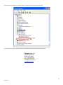
Expand the "Ports (COM & LPT)" item and look for "USB Serial Port" and note the COM number
You can use this COM port number to connect to Hyperterminal or other serial communications programs.
ThermoProbe, Inc.
112A JETPORT DR.
PEARL, MS 39208
Tel: +1 601.939.1831
Fax: +1 601.355.1831
[email protected]
www.thermoprobe.net
17
02/2013, JK