1
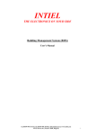
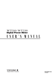
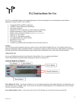
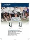
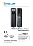
USER INSTRUCTIONS - TP7C & TP9
INTRODUCTION
This manual describes the basic function, use and safety instructions for a model TP7C or TP9 portable digital thermometer
instrument. These ThermoProbe instruments are intended for use in both hazardous (flammable) and non-hazardous areas under dry
conditions at ambient temperatures between -20 to 40°C. The instruments are not intended for use in permanent outdoor installations
and are not intended or tested for icing conditions. Additional means of protection should be used where the equipment may be
exposed to excessive external stresses (e.g. vibration, heat, impact, etc.).
SAFETY INFORMATION BEFORE USE
ThermoProbe thermometers are designed for safe operation in hazardous locations (Potentially Flammable or Explosive). The user
must have a working knowledge of appropriate safety instructions.
a) The inspector must have a thorough knowledge of the products to be measured and must know of the safety precautions to be
taken when working with the material to be measured.
b) The instrument shall be checked concerning severe defects; check that instrument is complete (including grounding/bonding
cable), has good batteries, etc. If necessary, check measurement accuracy. If any defects are found, the instrument should not be used
until repairs have been made.
c) The instrument, especially cable and probe, should be clean both for safety reasons and ease of use.
d) The physical measurement location should be evaluated for primary and secondary risks.
e) Power source must be removed before performing any maintenance.
f) Exchange of components other than the batteries may compromise ATEX/IECEx certification and shall only be undertaken by
Thermoprobe or one of its qualified service providers. See also “Authorized Repair” section.
g) To reduce the risk of fire or explosion, this device must be bonded to the tank according to clause 6.3.2 e), IEC/EN 60079-14
before and during introduction into the tank and shall remain bonded until complete withdrawal from the tank.
h) The device must remain bonded to ground/earth using the provided connection whenever a hazardous atmosphere could be present
as well as during situations where electrostatic charging can occur such as the unwinding/winding of the thermometer cable or filling
or emptying of the tank.
CAUTION: In the event that any part of the instrument should become electrostatically charged in a potentially hazardous location,
follow company policies for testing and clearing the area of any hazardous gases before attempting to bond the instrument to earth
ground. If this is not possible allow sufficient time for the instrument to naturally dissipate any charges before attempting to bond to
earth ground. Given the atmosphere, this could take several hours.
GUIDANCE NOTE
Problems with aggressive substances and environments: Be aware of aggressive substances and that extra protection may be needed.
Caustic soda, highly basic and acidic substances will erode aluminum and copper ground clip and wire. The Sensor-Cable assembly
has external surfaces of stainless steel and fluoropolymer material. Exposure to Excessive heat can melt the plastic components of
the instrument.
11/2012, JK
Safety Approvals for TP7C and TP9:
II 2 (1) G Ex ib [ia] IIB T4
Applicable Standards are:
IEC 60079-0:2007 Ed. 5
IEC 60079-11:2006 Ed. 5
EN 60079-0: 2009
EN 60079-11:2007
Agency or Safety Designation
IECEx
IECEx
Europe: ATEX
Europe: ATEX
INTRINSIC SAFETY
Intrinsically safe equipment is defined as "equipment and wiring which is incapable of releasing sufficient electrical or thermal
energy under normal or abnormal conditions to cause ignition of a specific hazardous atmospheric mixture in its most easily ignited
concentration." (ISA-RP12.6) This is achieved by limiting the amount of power available to the electrical equipment in the hazardous
area to a level below that which will ignite the gases.
In order to have a fire or explosion, fuel, oxygen and a source of ignition must be present. An intrinsically safe system assumes the
fuel and oxygen is present in the atmosphere, but the system is designed so the electrical energy or thermal energy of a particular
instrument loop can never be great enough to cause ignition.
TP7C/TP9 Hazardous
Location application:
Hazardous Area
Zone 0 ‘ia’
Temperature
Probe
Hazardous Area
Zone 1 ‘ib’
TP Instrument
Body
Probe Cable
Ground Connection
Zone 0: Where ignitable concentrations of flammable gasses vapors or liquids can exist all of the time or for long periods of time under normal operating conditions.
Zone 1: Where ignitable concentrations of flammable gasses vapors or liquids can exist some of the time under normal operating conditions.
11/2012, JK
REPLACING BATTERY
WARNING:
• Batteries must be changed in Non-hazardous area.
• Batteries must be of correct approved type.
• Batteries must be installed with correct polarity making sure the (+) end of the battery is aligned with (+) symbol embossed
in the battery case.
• New batteries must not be mixed with old batteries. Batteries must not be mixed with batteries of other manufacturers.
• Batteries must not be installed with polarity reversed where one cell could charge another cell.
a) Ensure the instrument is in a non-hazardous area.
b) Remove the 3 screws holding the front cover on the TP7C or the 2 screws holding the front cover on the TP9.
c) Remove battery retaining device, push one battery towards the spring contact and lift battery up from the holder, and then remove
the remaining battery.
d) Install each new battery making sure the (+) end of the battery is aligned with (+) symbol embossed in the battery case.
e) Replace the retaining device and reinstall the cover.
CERTIFIED Batteries for the TP9 and TP7C are as follows:
Manufacturer
Type
Part Number
Duracell
Panasonic
GP (Gold Peak)
AA (LR6) Alkaline
AA (LR6) Alkaline
AA (LR6) Alkaline
MN1500
LR6XWA
GP15A
MEASURING PROCEDURES
See www.thermoprobe.net for video on proper use of this instrument. Contact your distributor or ThermoProbe Inc. for names of
training facilities. Refer to American Petroleum Institute measurement standard Chapter 7.2.
When the temperature has stabilized both Up and Down arrows will be displayed.
If you wish to log the temperature for averaging purposes, rapidly press the “On” button twice. An acknowledgment of a saved
reading will occur with a display of “LoggEd”. If the display shows “-------“ then reading was not logged due to a non-stabilized
temperature. The real time temperature will then be displayed again indicating the next reading is ready to be taken.
If you have completed all the readings needed for your operation, the “f” Button may be used to “LiSt” all the readings logged and
“At” average of the logged temperatures. Document your readings and average temperature before powering off the device.
Logged readings and average are not saved when the instrument powers off. (Note: The instrument will automatically power off 20
minutes after the last button push.)
AUTHORIZED REPAIR
It is recommended that service beyond the scope of this manual be performed by ThermoProbe, Inc. or one of its authorized
distributors.
11/2012, JK
USER INTERFACE
Power Button
Function Button
“Power” Button
Pressing the Power button once will turn on the device. The instrument will shut off automatically within 20 minutes.
Pressing the Power button twice (within 1 second) will save whatever reading is on the display.
Pressing and holding the Power button will and shut the instrument off and clear all logged and averaged readings.
Power button
One quick push
Two quick presses
Hold and Release
when display reads “oFF”
Operation
Display
Power On
Saves current reading
“LoggEd”
Power Off
(Clears Readings)
“oFF”
Function “f” button
Press and Hold the Function Button “f” to display options in a menu
format. When the desired function is displayed release the button.
Up to 10 readings can be saved and averaged.
Hold and Release when the
display reads:
“LiSt”
“At”
“C-F”
“dEC”
Function (“f”)
displays all saved readings
Example on Display
“rEAd 1, 78.2 F”, “rEAd 2,
74.4 F”, etc.
displays the average of all saved readings
“At, 76.3 F”
Changes units
Changes units resolution (0.1 or 0.01)
“76.3 F” or “24.6 C”
“76.3 F” or “76.36 C”
Backlight
When the instrument is operating in low-light conditions a photocell will detect this situation and permit the backlight to function.
Battery Check
When the voltage of the batteries is low, the device will indicate “Lo bAtt” on the display before resuming normal display functions.
When the batteries are low the backlight will not operate in order to conserve power while the user completes his operations. Replace
batteries as soon as possible in a safe location after “Lo bAtt” is noticed, this will ensure backlight operation, and avoid possible
malfunctioning. Do not attempt to calibrate the instrument if the “Lo bAtt” has been displayed since the new calibration values may
not be properly stored to memory.
11/2012, JK
Error Codes
ErrHI indicates the sensor is operating above its temperature limit, the Probe Assembly is open circuited from a cut or broken
section, or the cable is not properly inserted at the circuit board terminal. The most common cause is a damaged cable.
ErrLO indicates the sensor is operating below its temperature limit, the Probe Assembly is short circuited due to a smashed or cut
section, or the cable wire polarity is reversed at the circuit board terminal. The most common cause is a damaged cable.
nO rEAd -the user accessed "List" or "At" before saving temperatures.
REPLACING THE PROBE ASSEMBLY
NOTES:
1) Replacement of the probe assembly requires re-calibration of the device. Replacement should only be done by experienced
personnel and if calibration equipment is available.
2) Please refer to IEC/EN 60079-19 when making the repair
3) Only use replacement probe assemblies obtained from ThermoProbe, Inc. or one of its authorized distributors with part
specifications as follows:
a) First follow REPLACING BATTERY instructions a through c to remove batteries.
b) On the circuit board push the terminals clamps down and remove the wires noting the wire lead color code arrangement.
White – positive sensor wire
Black – negative sensor wire and sheild
c) Set the cover and circuit board aside and remove the strain relief knot in cable assembly.
d) Unwrap the cable from the assembly and pull the cable free of the rubber grommet.
e) Insert the new cable wire through the rubber grommet and then pull several inches of cable slack past the grommet.
f) Tie a simple overhand knot in the cable at the grommet for strain relief and pull any slack through the grommet.
g) On the circuit board, push the terminal clamps down and insert the new wire leads making sure the black wire lead is installed in
the terminal indicated with black paint. (See Figure 1)
h) Reinstall the batteries and cover and re-spool the cable assembly.
i) Perform a calibration.
Negative Terminal
indicated by black
marking
11/2012, JK
Figure 1: Probe Assembly Lead Attachment
CALIBRATION PROCEDURE
•
•
•
•
•
The calibration mode should only be accessed by qualified personnel with proper equipment; otherwise calibration integrity
may be compromised. Read the following instructions carefully.
A 2-Point, 3-Point or a 4-point calibration can be performed. A third or fourth point is only necessary when high accuracy is
required at temperatures of 300°F and higher. You must have the proper equipment for every point of calibration.
Do not attempt to calibrate the instrument if the “Lo bAtt” has been displayed since the new calibration values may not be
properly stored to memory.
Refer to API 7.2 or another recognized standard for routine calibration verification recommendations.
Calibration must not be performed in any environment considered to be hazardous.
Equipment needed:
•
•
•
Ice Bath or other low temperature bath with certified reference thermometer.
Warm to hot fluid bath between 20°C (approx 68°F), or higher up to 90°C (approx 194°F) with certified reference
thermometer. (see Note)*
Optional high temperature oil bath at about 150°C/300°F and certified reference thermometer.
*Note for limited calibration: If entire range capability of instrument is not required, the 2 point high adjustment can be made at
a temperature relatively close to the common temperature of the liquid measured and accuracy will be maintained within the
limited range. For example: If liquid product to be measured is commonly less than 38°C (approx. 100°F), then a “high point”
calibration can be made near that temperature. Temperature accuracy above this calibration point cannot be assured.
Calibration Button
Function Button
11/2012, JK
Power Button
To calibrate proceed with the following steps:
1. A hidden Calibration Button is located on the front overlay underneath the ThermoProbe logo (see diagram above).
While the instrument is on, first press and hold the “f” Button, and then press and hold the hidden Calibration Button until the
display scrolls through the options 2Pt CAL, 3PtCAL, 4PtCAL, CAnCEL. When the desired option is displayed, release the
buttons.
The Calibration Mode can be exited in two ways. If the user is not ready to enter the calibration mode, the CAnCEL option can be
chosen. If a user needs to end a calibration before completing it then STEP 3 below provides an option to safely exit the operation
and revert to previously stored calibration values.
2. The device is now in calibration mode.
The last character on the right side of the LCD will now be blinking “A” representing the lowest temperature calibration point.
“b” = the next higher temperature point
“C” = the next higher temperature point (only used in 3-point calibration or 4-point calibration mode)
“d” = the highest temperature point (only used in 4-point calibration mode)
While at each temperature calibration point the arrows will flash 3 times when the temperature reading stabilizes.
Calibration can be performed to hundredths of a degree.
The “On” Button increases the display reading, the “f” Button decreases the display reading.
Holding the “On” Button or the “f” Button adjusts 0.1 degrees increments.
Momentary Presses of the “On” Button or the “f” Button for less than 0.5 seconds adjusts 0.01 degrees for every press.
When you leave calibration mode the display remains in hundredths for that session only to allow you to re-check the temperatures.
Once you have turned the device off, the display will only show in tenths.
3. Once the temperature has stabilized, using a certified reference device check the actual temperature in the bath and use the “On”
Button or the “f” Button to adjust the device to the actual temperature. The “On” button will decrement the readings and the “f”
Button will increment the reading. Once the device temperature matches the actual temperature, press the Calibration Button to
save the setting. The display will scroll "SAUE" or “CAnCEL”. If the “SAUE” option is chosen the blinking letter will change to
represent the next temperature level (A => b). If the “CAnCEL” option is chosen then the calibration procedure is exited and the
prior calibration values are re-activated.
4. Move the probe to the next bath and repeat step 3. After you save the highest temperature point the display will flash "rEAdY"
and the new calibration settings will be in effect. The buttons will now resume their normal operating functions. The calibration
settings are saved to flash memory when the device is turned off. The unit will not turn off automatically, manually turning the unit
off saves the calibration data.
Ensure that your calibration efforts are saved by shutting the instrument off now.
Calibration Error Codes
1. nO CAL - This is seen after the instrument is turned on when no calibration data has been saved yet. The device must be
calibrated before using.
2. CAL Err2 - This is seen after the instrument is turned on when there is a flash memory error or the calibrations data is corrupted.
When this error is displayed the device will inaccurately display temperatures without using any calibration data. This error probably
indicates a device error. The user should contact the distributor or ThermoProbe, Inc.
3. CAL Err3 - This is seen after the instrument is turned on when calibrations data reads OK, but is invalid. This could be an error in
calibrating the device. When this error is displayed the device will read temperatures without using any calibrations data. This error
could occur as a result of not saving the low or mid temperature before moving the device to the next bath during calibration. The
device should be recalibrated.
ThermoProbe, Inc.
11/2012, JK
112A JETPORT DR.
PEARL, MS 39208
Tel: +1 601.939.1831
Fax: +1 601.355.1831
[email protected]
www.thermoprobe.net