1
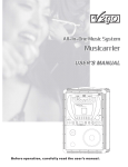
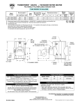
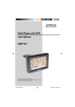
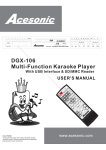
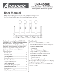
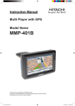
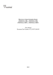
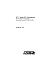
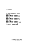
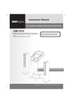
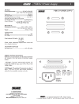
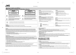
Before operating this device, please
carefully read the user’s manual, and
retain for future reference.
Table of Contents
Warnings, Cautions and Others
___________
Front Panel Controls & Functions _
Rear Panel Controls & Functions
Con nec tions _
__________
6
___________
7
__________________
Specifications _
_________________
Troubleshooting
_________________
2
3
8
12
12
Warnings, Cautions and Others
Mises en garde, precautions et indications diverses
For Canada/Pour le Canada
CAUTION
THIS DIGITAL APPARATUS DOES NOT EXCEED
THE CLASS B LIMITS FOR RADIO NOISE
AS
EMISSIONS FORM DIGITAL APPARATUS
"
" SET
OUT IN THE INTERFERENCE-CAUSING
EQUIPMENT STANDARD" ENTITLED DIGITAL
"
APPARATUS, ICES-003 OF THE DEPARTMENT
OF COMMUNICATIONS. CET APPAREIL
NUMERIQUE RESPECTE LES LIMITES DE
BRUITS RADIO ELECTRIQUES APPLICABLES
AUX APPAREILS NUMERIQUES DE CLASSE B
PRESCRITES DANS LA NORMESUR LE
MATERIEL BROUILLEUR: APPAREILS
NUMERIQUES , NMB-003 EDICTEE PAR LE
MINISTRE DES COMMUNICATIONS.
RISK OF ELECTRIC SHOCK
DO NOT OPEN
CAUTION: TO REDUCE THE RISK OF ELECTRIC SHOCK.
DO NOT REMOVE COVER (OR BACK).
NO USER SERVICEABLE PARTS INSIDE.
REFER SERVICING TO QUALIFIED SERVICE PERSONNEL.
The lightning flash with arrowhead symbol, within an
equilateral triangle is intended to alert the user to the
presence of uninsulated dangerous voltage within the
product's enclosure that may be of sufficient magnitude
to constitute a risk of electric shock to persons.
The exclamation point within an equilateral triangle is
intended to alert the user to the presence of important
operating and maintenance (servicing) instructions in
the literature accompanying the appliance.
Caution
WARNING
Disconnect the mains plug to shut the power off
completely. The POWER is not disconnected from
the mains line when the POWER button on the front
panel is pressed in.
To reduce the risk of fire or electrical shock, do not
expose this appliance to rain or moisture.
SAFETY INSTRUCTIONS
1. Read Instructions
All the safety and operating instructions should be read
before the product is operated.
10. Power-cord Protection
Power-supply cords should be routed so that they are not
likely to be walked on or pinched by items placed upon or
against them, paying particular attention to cords at
plugs, convenience receptacles, and point where they
exit from the appliance.
2. Retain Instructions
The safety and operating instructions should be retained
for future reference.
11. Lightning
To protect your product from a lightning storm, or when it
is left unattended and unused for long periods of time,
unplug it from the wall outlet and disconnect the antenna
or cable system. This will prevent damage to the product
due to lightning and power-line surges.
3. Heed Warnings
All warnings on the product and in the operating
instructions should be adhered to.
4. Follow Instructions
All operating and use instructions should be followed.
5. Attachments
Do not use attachments not recommended by the product
manufacturer as they may cause hazards.
12. Carts and Stands
The product should be
used only with a cart or
stand that is
recommended by the
manufacturer.
6. Cleaning
Unplug this product from the wall outlet before cleaning.
Do not use liquid cleaners or aerosol cleaners. Use a dry
cloth for cleaning.
7. Ventilation
The appliance should be situated so its location does not
interfere with its proper ventilation. For example, the
appliance should not be situated on a bed, sofa, rug, or
similar surface that may block the ventilation slots.
12 A. An applicance and cart combination should be moved
with care. Quick stops, excessive force and uneven
surfaces may cause the appliance and cart combination
to overturn.
8. Heat
The appliance should be situated away from heat sources
such as radiators, heat register, stoves, or other apparatus
(including amplifiers) that produce heat.
13. Power Sources
product should be operated only from the type of power
source indicated on the marking label. If you are not sure
of the type of power supply to your home, consult your
product dealer or local power company.
9. Water and Moisture
Do not use this unit near water. For example, near a
bathtub or in a wet basement and the like.
3
SAFETY INSTRUCTIONS
22. Servicing
Do not attempt to service it yourself as operating
instructions, do not attempt to service it yourself as
opening or removing covers may expose you to
dangerous voltage or other hazards. Refer all servicing
to qualified service personal.
14. Grounding and Polarization
This product is equipped with a polarized alternatingcurrent line plug (a plug having one blade wider than the
other). This plug will fit into the power outlet only one way.
This is a safety feature. If you are unable to insert the plug
fully into the outlet, try reversing the plug. If the plug
should still fail to fit, contact your electrician to replace
your obsolete outlet. Do not defeat the safety purpose of
the polarized plug.
15. Power Lines
An outside antenna system should not be located in the
vicinity of overhead power lines or other electric light or
power circuits, or where it can fall into such power lines
or circuits. When installing an outside antenna system,
extreme care should be taken to keep from touching such
power lines or circuits as contact with them might be
fatal.
16. Overloading
Do not overload wall outlets, extension cords, or integral
convenience receptacles as this can result in a risk of fire
or electric shock.
17. Object and Liquid Entry
Never push objects of any kind into this product through
openings as they may touch dangerous voltage points or
short-out parts that could result in a fire or electric shock.
Never spill liquid of any kind on the product.
18. Replacement Parts
When replacement parts are required, be sure the
service technician has used replacement parts specified
by the manufacturer or have the same characteristics as
the original part. Unauthorized substitutions may result in
fire, electric shock, or other hazards.
19. Safety Check
Upon completion of any service or repairs to this product,
ask the service technician to perform safety checks to
determine that the product is in proper operating
condition.
20. Damage Requiring Service
Unplug this product from the wall outlet and refer
servicing to qualified service personnel under the
following conditions:
A. When the power supply cord or plug is damaged.
B. If liquid has been spilled, or objects have fallen into the
product.
C. If the product has been exposed to rain or water.
D. If the product does not operate normally by following
the operating instructions. Adjust only those controls that
are covered by the operating instructions as an improper
adjustment of other controls may result in damage and
will often require extensive work by a qualified technician
to restore the product to its normal operation.
E. If the product has been dropped or damaged in any
way.
F. When the product exhibits a distinct change in
performance-this indicates a need for service.
4
Thank you for purchasing products from V2GO Technology!
V2GO Technology Inc., located in Los Angeles, CA, USA, is one of the
world's most innovative manufacturers of quality audio and video
electronic products. V2GO is proud of its strong R&D, quality control and
production resources that have resulted in a line of products that are
technologically advanced and are of superior quality and durability.
Providing quality products and services at a reasonable cost to the user is
the basis of V2GO's corporate philosophy. The ability to convert intangible
ideas into marketable products is V2GO's unchallenged advantage. V2GO
- Making your life a little more fun.
Contact us:
Interested in becoming a retailer or distributor of V2GO products? Contact our sales
department at [email protected]
For general information about V2GO products, contact us at
[email protected]
For Technical Assistance, email us at [email protected]
Monday to Friday, 8:30am to 5:30pm PST.
Please visit our website at www.V2GOTECH.com to find additional information about
V2GO products and services.
5
Front Panel Controls & Functions
11
11
Right speaker
Left speaker
10
POWER
MIC 1 VOL
MIC 2 VOL
ECHO
MIC 1
0
1
10 0
2
10
3
BBS
0
4
MUSIC VOL
MIC 2
5
10 0
6
9
10
7
8
1 . POWER SWITCH:
Turn on/off the speaker.
2 . MIC 1 VOL UME : Control the volume of microphone 1.
3 . MIC 2 VOLUME: Control the volume of microphone 2.
4 . MIC 1 INPUT JACK: Connect microphone 1 (please refer to page 11).
5 . MIC 2 INPUT JACK: Connect microphone 2 (please refer to page 11).
6 . ECHO CONTROL: Control the echo level of the microphones.
7 . MUSIC VOL UME : Control the music volume.
8 . BBS SWITCH: Press this button to get the bbs effec t (base enhancement) .
9 . BBS INDICATOR: BBS function on when light on .
10
. POWER INDICATOR: Power on when light on .
11
. COVER: Removable cover.
6
Rear Panel Controls & Functions
7
Right speaker
Left speaker
3
6
L
R
L
INPUT
4
R
MIXER OUTPUT
5
SPEAKER
To Right Speaker
Karaoke Speaker With Amplifier
MODEL NO.: GO-400(Left)
INPUT: AC100V/AC230V 50/60Hz
Serial Number:
LA CALIFORNIA U.S.A
POWER IN
POWER SELECT
AC230V
AC115V
1
Made in China
2
1 . POWER IN PLUG: AC in.
2 . POWER SELECT: Switch between AC 11 5 V/230V power input. Be sure to match the voltage of
power supply.
3 . L/R INPUT JACKS: For audio signal input.
4 . L/R MIXER OUTPUT JACKS: For audio signal output. Can be connected to the audio signal
input jacks on a recordable equipment.
5 . SPEAKER OUTPUT JACK: Connect to Right speaker input jack.
6 . SPEAKER INPUT JACK: Connect to the left speaker output jack
7 . THERMAL SINK: Thermal sink helps cool the amplifier inside the speaker
Caution: The thermal heat-sink (#7, in figure above) on the back of the speaker
becomes HOT after prolonged speaker use. Please do not touch.
7
Connections
Part 1 Power Connection
Plugging The Power Cord of The GO-400 Into The AC Outlet
Note: Before connecting power cord, please make sure the power voltage selector
is correctly set for your local power voltage.
Warning: After use, please turn off the GO-400. During periods of
prolonged non-operation, it is recommended that you disconnect the power cord.
Left Speaker
AC11 5 V/230V 60-50Hz
L
R
L
INPUT
R
MIXER OUTPUT
SPEAKER
To Right Speaker
Karaoke Speaker With Amplifier
MODEL NO.: GO-400(Left)
INPUT: AC100V/AC230V 50/60Hz
Serial Number:
LA CALIFORNIA U.S.A
POWER SELECT
POWER IN
AC115V
8
Made in China
AC230V
Connections
Part 2: Audio Input Connection
How to input the Audio
1.Connect ing to a DVD player.
1.1. Connect ing to a DVD player.
Plug one plug end of the cable into the GO-400 input jack and the other end to the DVD audio-out jack
1.2.Connect ing the two speakers.
Connect one plug end of the RCA cable to the left speaker's speaker jack and connect the other end to the
right speaker's RCA jack.
L
R
L
INPUT
R
MIXER OUTPUT
SPEAKER
To Right Speaker
Karaoke Speaker With Amplifier
MODEL NO.: GO-400(Left)
INPUT: AC100V/AC230V 50/60Hz
Serial Number:
LA CALIFORNIA U.S.A
Made in China
POWER SELECT
POWER IN
AC115V
AC230V
GO-100
POWER INPUT
FR
SW
Y/R
PB/G
PR/B
VIDEO
L
SL
SR
CEN
ML
MR
COAXIAL
S-VIDEO
OPTICAL
CAUTION
RISK OF ELECTRIC SHOCK
DO NOT OPEN
9
L
KARAOKE DVD PLAYER
VOCAL OUTPUT
SCART
VGA
KARAOKE OUTPUT
FL
R
R
MODEL NO.: GO-100
INPUT: ~100V-240V 50/60Hz
Serial Number:
LA CALIFORNIA U.S.A
MAKE IN CHINA
1.Manufactured under license from Dolby Laboratories.
2. Dolby , Pro Logic and the double-D symbol are
trademarks of Dolby Laboratories.
~100V-240V(50-60Hz)
Connections
Part 2: Audio Input Connection
2. Connect ing to a PC.
1.1. Connec ting to a PC:
Connect the 1/8" plug of cable to the pc audio out jack and connect the RCA plugs on the other end of
cable to the input jacks at the back of the left speaker according to the color code.
1.2. Connect ing the two speakers.
Connect one end of the RCA cable to the left speaker's speaker jack and connect the other end to the
right speaker's RCA jack.
L
R
L
INPUT
R
MIXER OUTPUT
SPEAKER
To Right Speaker
AUDIO OUT
L
R
INPUT
L
R
MIXER OUTPUT
SPEAKER
To Right Speaker
POWER
MIC 1 VOL
MIC 2 VOL
ECHO
MIC 1
0
10 0
10
MUSIC VOL
MIC 2
BBS
0
10 0
10
10
Connections
Part 3: Karaoke Connection
3.OK,
GO-400
3. Karaoke Connection:
Follow this diagram to easily connect your GO-400 speakers to a karaoke system.
Once connected, you’ll be able to enjoy many hours of karaoke fun.
Audio in
L
R
INPUT
L
R
MIXER OUTPUT
SPEAKER
To Right Speaker
L
R
INPUT
L
R
MIXER OUTPUT
SPEAKER
To Right Speaker
POWER
MIC 1 VOL
MIC 2 VOL
ECHO
MIC 1
0
10 0
10
MUSIC VOL
MIC 2
BBS
0
10 0
10
Y/R
PB/G
ML
MR
Audio out
VIDEO
Video out
S-VIDEO
DVD player
11
Specifications
Model N o .
Power requirements
GO-400
AC11 5 V/230V 50-60Hz
Power consumption
60W/pair
Audio out
15W+15W RMS 1K/6Ω
Karaoke input sensitivity
<20mV
Dimensions
Left speaker:150 2 20 2 43(5.9"x8.6"x9.6")
Right speaker:150 1 80 2 43(5.9"x7.1"x9.6")
Left speaker: 3.6KG(8lbs)
Right speaker: 2.3KG(5.1lbs)
Weight
Troubleshooting
Symptom
Possible Reasons
No Power
Power cord is not secure, or
outlet is not functional
No S ound
Check the volume control
12
Solution
Secure the power cord, check
functionality of outlet
Turn up the volume
9528 Rush St#I
South El Monte CA, 91733
Tel: 626-582-8098
Fax: 626-582-8908
Toll free: 1-877-566-V2GO(566-8246)
13