1
User's Manual
Twin Tank Water Quality System
WATER QUALITY
Congratulations!
Your Twin Tank Water Quality
System was designed and
manufactured for optimal
performance with minimal
maintenance. We know you will
enjoy its many benefits for years
to come. Thank you for choosing
our system.
Ownerluser responsibility
Please read this User's Manual
carefully and familiarize yourself
with your new Water Quality
System. With a little preventative
maintenance, you can reduce the
need for service calls.
Before calling for service,
Is the unit protected from
excessive heat or dampness
from sweating pipes or
leaks?
please check:
= Is the power cable
connected to the 12 volt
transformer? Is the transformer plugged into a 120V,
continuously hot electrical
outlet?
= Is the water pressure supply
to the unit within the limits
set by the manufacturer or
has the water source been
changed?
Does the unit have a
sufficient supply of approved
salt that has not become
hard or bridged?
1s the unit protected from
freezing, including drain
lines and lines to and from
the brine-tank?
Be sure your dealer fills in the information below
when your Water Quality System is installed.
Model
Water Analysis
Controller Number
Hardness
GPG
Valve Serial Number
Iron
PPM
Date of Installation
Dealer
Address
Service Phone
.
PH
Other
Installation Checklist
Cl Water pressure should be at
least 20 pounds per square
inch. If pressure is over 80
PSI, install a pressure reducer.
(Most hot water heaters are
rated at 75 PSI worhng
pressure.)
Cl Flow rate should be at least
4.5 gallons per minute at
20 PSI
Cl Drain availability-floor
drain, washer drain, etc. Run
overhead no more than 5 feet
above the water softener.
Increase the size of the drain
for long runs. All plumbing
codes require a %inch air gap
at the end of the drain line.
O Electricity-continuously
receptacle of 120 volts,
60 cycles.
hot
O Water quality-If the water
supply contains sulphur, iron,
bacteria, tannins, algae, oils,
acids, salt or other unusual
substances, your system may
require pretreatment.
...
Do
Install the system after the
pressure tank. Ask for advice
on any special plumbing
arrangement.
Comply with all local
plumbing and electrical
codes.
Examine inlet piping. If it is
clogged, replace or clean it.
Minimum size should be 314
inch nominal.
Install gravity drain on the
brine tank.
Don't
=
...
Don't install if inlet water
temperature exceeds
120°F.
Don't allow heat from
torches t o be transferred to
plastic o r valve parts.
Softener Installation
(Twin Tank System)
1. Select location for water softener.
Place as close as possible to pressure tank (well water) or water meter (city water).
Place close to floor drain, laundry drain or sump.
Attach softener to the main water line before the water heater.
Bypass outside water faucets to conserve soft water and salt.
Place softener where it will not freeze.
A 120V electrical outlet must be nearby. If softener is to be placed outside, care must be taken to
protect all electrical wires, transformer and electronics.
Protect softener from direct sunlight.
Floor surface must be smooth and level.
2. Open boxes to verify that there is no damage from shipping and that all parts are included.
Mounting bracket with wiring, twin tank board and turbine with quest nut.
12V (black) transformer.
siack knobs and studs (in plastic bag attached to control valve).
Three way plastic adapter or optional brass bypass valve.
= Four connector bars, pan head screws and nuts, two clevises.
3. Provide an in house bypass valve (3a) or
optional brass bypass valve. (3b)
4. Connect the two resin tanks.
DRAIN
l N LET
Grease all openings and O-rings with silicone grease.
Insert the 1" and 112" black or gray nipples into
OUTLET
both sides of the three way adapter (or optional
three way brass bypass valve).
Place one resin tank in its proper place for installation.
Press the nipples into the openings of the resin tank control valve.
Move the second tank into position near the first tank and press them together in order to insert the
nipples on the other side of the adapter into the control valve of the second tank.
Secure both sides using the connector bars and pan head screws. Be sure the nuts are tight.
Attach clevises in' the top holes above the connector bars. (4)
NOTE: All Genus T ~ r i ncabinet models are shipped from the factory completely assembled with the
exception of the turbine and transformer.
5. Connect the softener.
For Genus Twin:
Move the softener into place for installation.
Remove the hood and controller.
For all twin tank models, including the Genus Twin:
TURBINE
TURBINE
ASSEMBLY
HOUSING
Remove the sensor cable from the turbine.
Spread the clips on each side on the turbine housing and pull sensor out.
Remove the small O-ring from around the mouth of the sensor cavity.
Remove the impeller assembly from the turbine housing (replace after lines have been flushed).(5)
Attach the turbine to the lower 1" (outlet) opening of the noryl adapter using a 1" PVC coupling.
Leave the sensor cavity in a horizontal position for easy access and to prevent water from collecting
in the cavity.
= Connect the other end of the turbine to the soft water line of the three way bypass. Use the quest nut
o r optional 1" nut with 4" copper tail pipe to provide a union for access to the impeller assembly.
= Plumb the main hard water line into the top 1" (inlet) opening on the adapter or optional brass bypass.
6. Install Drain Line
Install a 518" I.D. flexible tube for drain using a 112" barb fitting (not included) in the 112" opening on
the adapter or optional brass bypass.
Increase the size of the drain line if it is to run overhead or for a long distance.
7. Install Brine Tank.
Remove the safety float from the brine well.
Check the valve fittings.
= Remove the rubberband from the bottom of the float and return the float to the brine well.
NOTE: This is not necessary on Genus Twin models.
Attach the 318" clear brine harness to both control valves.
Connect the long tube to the upper elbow that protrudes from the side of the brine tank.
Connect a 112" I.D. plastic tube to the overflow elbow and run it to a floor drain.
8. Flush cuttings and other debris from the lines.
A. FOR A THREE VALVE BYPASS
Bypass the system by closing the inlet and outlet valves. Open the center bypass valve.
Open a nearby cold water faucet.
Open the main.water shut off valve to flush lines.
Place the bypass valve into service. Close the center valve. Open the outlet valve. Open the inlet valve
slowly to provide time for the air to escape from the resin tank. Then the tank has been thoroughly
flushed place the system back on bypass.
Loosen the quest nut on the turbine and reinstall the turbine assembly.
Retighten the quest nut.
= Place the bypass back in service again.
Close the water faucet.
B.FOR A B U S S BYPASS
Place the systenl into bypass. Pull the bypass rod up until it stops. Turn the knob 114 turn to lock it
into position.
Open a nearby cold water faucet.
Open the main water shut off valve to flush the lines.
Close the main water shut off valve
Place bypass valve into the service position. Turn the knob to realign it with the screw at the top of the
valve and push it all the way down.
Reopen the main water shut off valve slowly to provide time for the air to escape from the resin tank.
When the tank has been thoroughly flushed, place the system back on bypass.
Loosen the quest nut on the turbine and reinstall the turbine assembly.
Retighten the quest nut.
Place the bypass back in service again.
Close the water faucet.
9. Check the system for leaks.
10. Install the twin tank mounting bracket.
= Remove studs from plastic bags attached to the control valGes and screw them into the tapped holes in
the center of the top lid of the control valves.
Attach the solenoid harness to the control valves.(ll)
Connect the longer cable ($1) to the
control valve on the left.
Connect the short cable ($2) to the
control valve on the right.
Install the red and white cable to the
top solenoid coil ($1 brine draw).
Install the green and white cable to the
middle solenoid (#2backwash).
Install the black and white cable to the
bottom solenoid ($3 brine tank refill and purge).
/r--ll
?
NOTE: Use this same procedure for Genus Twin.
12. Complete the installation of the mounting bracket.
Placc the bracket over the top of both control valves and allow the studs in the top lids to come through
the small holes in the bracket. Secure the bracket with the black knobs.
Replace the hood on the Genus Twin.
13. Replace the turbine sensor.
Replace the turbine O-ring around the opening of the sensor cavity.
The proper position for the sensor is identified by a square projection on the clip and a corresponding
female depression on the turbine housing.
Slip the sensor into the cavitv.
Press gently until both sides of the clip have snapped into place.
14. Attach power cable to the two outside connections of the 12 volt
transformer. (14)
Plug transformer into a continuously hot 120V electrical outlet.
5
Softener Start Up
Remove the acrylic door from the front of the controller hood.
1. Program the TTC (twin tank controller)
STEP 1. SET TANK SIZE
Press scroll. The red light will move to "Tank Size".
Press the up or down button to select tank size. Tank size will appear on the display.
STEP 2. SET PULSE OR NON PULSE
Press scroll. The red light will move to "Pulse".
Press up or down button to set yes for pulse or no for non pulse. Yes or no ill appear on the display.
STEP 3. SET TURBINE SIZE
Press scroll. The red light will move to "Turbine Size". Press up or down button to set turbine size.
.75 for Braswell or 1.0 for Autotrol. .75 or 1.00 will appear on display.
STEP 4. SET COMPENSATED HARDNESS
Press scroll. The red light will move to "Compensated Hardness". Press up or down button to set the
correct grains of hardness. The speed increases with the length of time the button is depressed. Refer to
page 10 for instructions to calculate compensated hardness. The number of grains of hardness will
appear on the display.
STEP 5. RETURN TO SERVICE
Press scroll to return the system to service. The number of gallons before regeneration will appear on
the display and will count down to zero as water is being used.
2. Sanitize the softener
Remove the brine tank cover. Use a hose or pail to fill brine tank with 3 or 4 gallons of water.
Remove the brine well cover and pour about 113 cup of household bleach into the well. Replace
brine well cover.
Press the manual activate button on the TTC to start a regeneration. The first regeneration does
a number of things:
It draws the bleach into and through the system to sanitize it.
= It refills the brine tank to the water level needed for the next regeneration.
= It purges any remaining air from the resin tank.
= It settles the bed for service.
3. Fill the brine tank with salt.
Use a good brand of solar or pellet salt.
Be sure the brine well cover is in place.
Place salt in the brine tank.
= Replace brine tank cover.
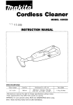
Twin Tank Controller (TTC)
DISPLAY
.
4
I
TANK 'IZE
SCROLL
CHANGE VALUE
KEYPAD
MANUAL
ACTIVATE
TURBINE SIZE(")
COMPENSATED
HARDNESS
d
GALLON COUNT
CHANGE TANKS
TEST
0
0
POWER
CHIP
DRIVERS
8
6 Q O
TURBINE TANK 1 TANK 2
SOLENOID
INDICATOR
LIGHTS
Additional Features For
bervice 'lechnicians
1. JP Prong -- TURBINE COUNTER
Important: Disconnect the turbine cable before using this feature.
Connect the prongs and maintain the connection.
The system will count down to 0 to determine if the controller will count gallons and initiate a
regeneration automatically.
2. JP3 Prong -- SWITCH TANKS
Connect the prongs T1 or T2 will appear on the display.
Connect the prongs a second time and the other tank will appear on the display.
After a few seconds the number of gallons remaining will reappear on the display.
3. JP 1 Prong -- TEST FEATURE
Connect the prongs to activate the test feature. TST 1 or TST 2 will appear on the display.
TEST FOR BRINE DRAW
Press the up button and the number 1 solenoid on the tank display will be activated.
Remove the brine line from the brine tank.
Place your finger over the end to-determine if a vacuum is being formed.
Replace the brine line.
= Press scroll again to de-energize the solenoid. The indicator light will disappear.
TEST FOR BACKWASH
IMPORTANT: Both the number one and the number two solenoid valves must be open for the
system to backwash.
= Press the up button to energize the number one solenoid.
-
Press the down button to energize the number two solenoid. Both the number 1 and the number 2
indicator lights will appear. Water will move up through the resin bed and can be heard running to
the drain.
Press the up button to de-energize the number one solenoid.
The indicator light will disappear. WAIT AT LEAST 10 SECONDS.
Press the down button again to de-energize the number two solenoid. The indicator light will
disappear.
TEST FOR BRINE REFILL AND PURGE
= Press the manual activate button to energize the number three solenoid. The number three indicator
light will appear. Water can be seen in the brine line running to the brine tank.
Press the manual activate button again to de-energize the number three solenoid.
TEST THE OTHER TANK IN THE SYSTEh4
Connect the JP3 prongs and the second tank ~7illappear on the display.
Repeat the procedure above.
Press scroll to return the TTC to its service mode. A number will appear on the display which
represents the number of gallons left until one of the tanks regenerates. As water is being used it will
count down to zero.
4. Manual activate -- MANUAL REGENERATION
Press manual activate button. The display ~7illindicate which tank is to be regenerated next. The tank
number will switch from number 1 to 2 every four seconds. Pick the number to be regenerated and
press the manual activate button again. This will complete a regeneration on the tank chosen. When
the regeneration on the first tank ends, repeat the above process to regenerate the second tank.
A regeneration may be stopped at any point by continuing to press the manual activate button to step
the system through all cycles to the end.
5. TURBINE INDICATOR LIGHT
A red light will flash when the turbine turns indicating water use.
IMPORTfiTT:DO NOT REMOVE SOLENOID WIRES WHEN THE SOLENOID IS ENERGIZED.
Programming the Controller
Calculating
compensated hardness
Compensated
hardness factors
1. Enter grains per gallon
of hardness here.
Result
Compensation
from step 3
factor
1-20 ............................................................. 1.1
21-40 ............................................................. 1.2
41-70 ............................................................. 1.3
71-100 ........................................................... 1.4
loo+ ............................................................. 1.5
2. Enter PPM of iron here.
+
3. Add lines 1 and 2 and
enter result here.
.
=
4. Enter the appropri5te
compensation factor
from chart at right here.
5. Multiply the sum from
line 3 by the
compensation factor
on line 4. Enter result
here.
EXAMPLE
x
-
10
+ 3
= 13
x 1.1
= 14.3
Grains
PPM Iron
Total Hardness
Compensation Factor for 13 gr HiO
Compensated Hardness
Quick Service Guide
Loss of water pressure
Unit fails t o regenerate
Cause
Solution
Cause
Solution
Electrical service to unit
has been interrupted
Assure constant power
source
Iron buildup in the lines
to the unit
Clean or replace lines
TTC is defective
Replace TTC
Iron buildup in the unit
Solenoid coils burned out
Replace solenoid coils
Clean unit with acid or
salt additive
Drain is frozen or plugged
Thaw out, replace or
clean drain
Trash in the system
Clean complete control
valve and bypass. Add
pre-filter.
Clogged upper distributor
Remove and clean upper
distributor.
Unit delivers hard water
Cause
Solution
Bypass open
Close bypass
Loss of resin through house lines
Bypass O-ring damaged
Replace 0-ring(s)
Cause
Solution
No salt or salt is hard
or bridged
Add salt or break up
bridging
Defective lower distributor
Replace lower distributor
Aspirator plugged
Clean aspirator
Insufficient water
refilling brine tank
Check ii3 solenoid coil,
refill flow control and tank
size setting
Cracked riser tube
Replace riser tube
Back pressure on drain
Correct drain
Broken vacuum breaker
spring
Replace spring
$2 solenoid inoperative
Clean solenoid valve
Replace solenoid coil
Iron in conditioned water
Cause
Solution
Salt dosage too low
Reset controller or
increase size of flow
control
No salt usage
Correct bridging
Oxidized or colloidal iron
Install post-filter
(1 or 2 micron)
Excessive water in brine tank
Unit uses t o o much salt
Cause
Solution
lmproper'tank size setting
Reset tank size
Excessive water in the
brine tank
Defective #1 solenoid.
Trash ill the brine
suction line or under the
brine elbow. Trash under
the $3 solenoid diaphragm.
Cause
Solution
#3 solenoid valve leaking
Clean ii3 solenoid valve
and check for bent
solenoid guide
Purge check leaking
Check for trash
Aspirator plugged
Clean aspirator
$1 solenoid coil inoperative
Replace f 1 solenoid coil
Blue dot elbow leaking
back to B.T. when unit is
not regenerating.
Replace elbow or
rubber ball - if worn.
Quick Service Guide, continued
Unit fails t o draw brine
Vacuum breaker leaks
Cause
Solution
Cause
Solution
Drain line pluggedifrozen
Clean drain line
Clean or replace
Aspirator plugged
Clean aspirator
Foreign matter in lip
of vacuun~breaker
split ball check.
R1 solenoid coil inoperative
Replace # I solenoid coil
Low water pressure
Correct pressure
Trash in the purge check
Clean purge check
Brine tube disconnected
Replace or tighten
brine tube
R2 solenoid coil inoperative
Clean or replace
solenoid coil
Odor
Cause
Solution
Anode rod
Remove rod
Sulfur of methane
Consult dealer
Other organics water
conditions changed
Other equipment
may be needed
Water runs t o drain continuously
Cause
Solution
Trash under $1 or t3
solenoid diaphragm
Clean or replace solenoid
diaphragms
Bent solenoid guide
Salty water after regeneration
Cause
Solution
Low water pressure
Increase water pressure
Replace solenoid guide
22 solenoid coil inoperative
Check power or replace
Broken solenoid spring
Replace solenoid spring
Cage O-ring broken
or missing
Replace cage O-ring
Too much water
in brine tank
Check brine refdl for
continuous flow
Cracked top lid
Replace top lid
Test water for chlorides
or nitrates
Add R.O. for drinking
or find a new source of
Piston return spring
caught
Replace or realign piston
return spring
Brine tank does not refill
Cause
#3 solenoid coil inoperative
~'olution
'
Replace solenoid coil
Refill flow control plugged
Clean or replace flow control
Driver on TTC inoperative
Replace TTC
#1 solenoid valve not
Remove trash from under
diaphragm. Check for
swelling - replace
seating out
supply
Air leak in brine
tubing harness
Replace or tighten
fittings that leak
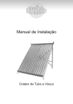
Control Valve Assembly
Ref. No.
Part Number
Description
Units per Assy.
1
1CV4 1820000**
Control valve body (brass or noryl)
1
2
AlCMBY 110850"
Control module assy, complete
1
3
lSCR612SS000
Upper distributor mounting screw
2
#6 X ' I 2 PL FH SM 18-8 SS
4
1ORING235000
Valve base O-ring #235
1
5
1CKSTEMGUIDE
Check stem guide
1
6
1ORING 121000
Riser tube O-ring #I21
1
7
1UD20SEG0130
Braswell upper distributor
1
8
5RT1050ABSO*
Riser tube
1
9
5LDlOSEG0000
Braswell lower distributor
1
10
3NUTK1032NPO
Black knob
1
11
1STUD10321SS
Stud ''I32 X 1 18-8 SS
1
Top lid mounting screw
1°/s2
lTOPLIDOOOO0
Top lid
I
lORING142000
Top lid O-ring #I42
I
15
1PISTONSPGOO
Piston return spring
1
16
1PISTONCAGEO
Piston cage
1
17
1ORING127000
Cage O-ring $127
3
18
SlASPAl 00000
Aspirator
1
19
1ORINGO10000
Aspirator O-ring #010
2
20
1PISTONCUPSL
Piston cup seal
1
21
SlPISTONWOOO
Piston
1
1PISTONGASTO
Piston gasket
1STEMCKSEALO
Stem check seal
1
1STEMCHECKOO
Stem check
1
13
23
'
24
"
X '12 PL RH MS 18-8 SS
Specify tank size
** Specify brass or noryl
Control Valve Assembly
Control Module Assembly
Ref. No.
Part Number
Description
Units per Assy.
1
1CMBDYOOOOOO
Control module body
1
2
1CMSEALOOOOO
Control module seal
1
3
1BMTFCl 000000
Backwash flow control
1
4
1BWFCSUPOOOO
Backwash flow control support
1
5
1BDRKEEPEROO
Brine draw and refill keeper
2
6
1RFCOOOOOOOOX
Refill flow control
1
7
1RFCRETAINOO
Refill flow control retainer
I
8
1516CKBALL00
51~6
diameter check balls
2
9
1PURGEGATEOO
Purge gate
1
10
lBRRING 14580
Brass ring
2
11
1PURGECKOOOO
Purge check
1
12
1PURGECKSEAL
Purge check seal
1
13
1VBSPRINGOOO
Vacuum breaker spring
1
14
1VBBALLCKOOO
Vacuum breaker split ball check
1
~
Felt pad
14B
15
1VBCOVEROOOO
Vacuum breaker cover
1
16
1SCR8716SToo
Vacuum breaker mounting screw $8 X '116
2
17
1SCR142034SS
Control module mounting screw
6
'14-20 X ' 1 4 PL PAN HD MS 18-8 SS
18
138BRELB18MP
Brass elbow 31s OD X ' 1 8 MPT
1
19
1INSSTOPOOOO
Ball check stop insert (outlet)
1
20
138BRELB18MP
Brass elbow 3/8 OD X
1
21
1INSSEATOOOO
Ball seat insert (inlet)
MPT
1
-?
23
a 1 SOLARMATURE
Solenoid armature
3
24
1SOLSPRINGOO
Solenoid spring
3
1SOLGUIDEOOO
Solenoid guide
3
1SOLRETAINTER
Solenoid retainer
3
lSCR8716ST00
Solenoid mounting screw #8 x ' 1 1 6 SS
9
1SOL11OBOOOO
Solenoid
25
-
28
* Specify tank size
14
-
p
~
Control Module Assembly
Limited Residential Warranty
This warranty is extended to the
original owner only and is not
transferable so subsequent owners
of this equipment.
To place the equipment under
warranty, THE WARRANTY REGISTRATION CARD MUST BE
COMPLETED IN ITS ENTIRETY
AND RETURNED TO 415 E.
WASHINGTON ST., Jackson,
Missouri 63755, within thirty (30)
days of installation by a factoryauthorized dealer.
Terms
The manufacturer warrants its
equipment to be free of defects of
workrnanship and materials for the
following terms.
Defective parts will be repaired or
replaced FOB Factory when received
from the original owner along with
the serial number.
Limitations
Your equipment must be sold by an
authorized dealer in order to receive
benefits of this warranty.
This warranty does not cover
damage due to:
abuse, misuse or neglect
excessive water pressure
(over 125 PSI)
excessive water temperature
(over 120°F)
5 Years: From date of manufacture
of all electronic controls, control
valve solenoids, gasiets, springs and
seals. The brine tank and mineral
tank if not exposed to direct
sunlight.
Bacterial iron, algae, sand or other
unusual substances present in the
water to be processed must be
removed before entering this
product.
There are no other warranties,
expressed or implied, other than
stated in this document to the extent
permitted by local and state laws.
freezing
- alterations
application or installation not in
accordance with published
factory specifications or the
instructions provided in the
users manual or not conforming
to local codes
- over-chlorinated water (over 1.5
ppm residual)
10 Years: From date of manufacture
of valve bodies.
This warranty does not cover labor
or service call costs incurred with
respect to the removal or replacement of any defective part or parts.
any other act of God not
reasonably within the dealer's
or manufacturer's power to
prevent or control.
The manufacturer, shall not be liable
for indirect, special or consequential
damages in connection with the use
of this equipment to the extent
allowed by local state laws.
Authorized Distributor
I
Braswell Water Quality Systems, h c .
415 E. Washington
Jackson, Missouri 63755
573 243-3660 573 243-5334 fax
WATER QUALITY
A S S O C I A T 1 0 N
MEMBER