1
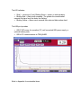
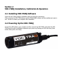
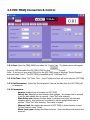
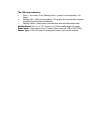
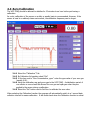
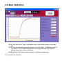
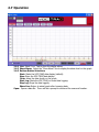
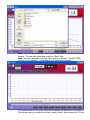
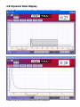
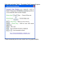
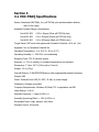
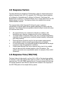
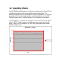
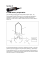
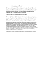
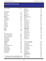
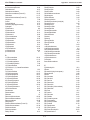
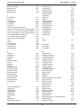
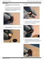
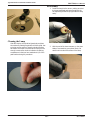
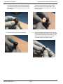
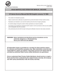
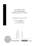
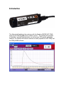
Introduction
This Manual will familiarize the customer with the Baseline MOCON VOC-TRAQ
using the piD-TECH® plus photo ionization sensor. This includes the principle
of operation, technical characteristics, as well as some PID-specific application
features. The Manual will instruct customers to easily operate the VOC-TRAQ and
the TRAQ-WARE software.
Section 1
1.1 VOC-TRAQ Overview
Portable Photoionization Detector (PID)
The VOC-TRAQ total volatile organic compound (TVOC) detector is an excellent
way to monitor and record TVOC’s. It operates using any PC with a Windows®
operating system. Using the award winning Baseline®-MOCON® piD-TECH® plus
photoionization detector makes the VOC-TRAQ the most reliable, accurate, and
inexpensive portable TVOC detector on the market.
Designed for ease of use all air quality consultants, safety engineers,
maintenance managers, or anyone concerned about TVOC’s in the indoor
environment.
The USB compatible VOC-TRAQ can operate while connected to a PC or it can
remotely store up to 36,000 sample readings with the detector’s internal memory
using the optional rechargeable power supply. Alarm levels are programmable
with LED and/or audible notification. The VOC-TRAQ is also compatible with
numerous USB accessory options.
The VOC-TRAQ is a simple compact design for monitoring TVOC’s in most
environments. The included software allows easy calibration, setup, display and
analysis.
The VOC-TRAQ consists of a cylindrical housing equipped with a USB port and a
3 color LED. On the top, there is are slotted openings that serve as an entrance
for analyzed gas
The photo ionization detector and associated electronic circuits are located inside
the housing.
The LED indicates:
• Slow (~ once every 5 sec) Blinking Green = power on and operating.
• Blinking Red = Alarm level exceeded. The greater the concentration
exceeds the alarm level the faster the flashing.
• Blinking Yellow = Alarm event occurred then returned below alarm level.
The USB port provides:
• USB 5 VDC power for operation (PC, wall connected USB power supply, or
optional battery pack).
• USB to PC communications to TRAQ-WARE.
Refer to Appendix for serviceable items.
Section 2
VOC-TRAQ Installation, Calibration & Operation
2.1 Installing VOC-TRAQ Software
Insert the VOC-TRAQ Software Installation disk and follow the instructions.
When complete the VOC-TRAQ drivers and the TRAQ-WARE software will be installed and ready to
use. Be sure to restart your computer after installation.
2.2 Powering Up the VOC-TRAQ
Connect the USB cable to your computer and then connect the VOC-TRAQ. Note that the VOCTRAQ goes through a initialization sequence upon power up (flashing red LED with beep, flash
amber, flash green, then beep).
2.3 VOC-TRAQ Connection & Control
2.3.1 Start: Open the TRAQ-WARE and select the “Control” tab. The display above will appear.
From the COM tab select the VOC-TRAQ COM Port then
“Connect”.
Note: If you are not sure what COM port is the VOC-TRAQ check in Windows “Device Manager”
and look under “Ports”. The VOC-TRAQ is identified as the “USB Serial Port”.
2.3.2 Set Time: Select “Set” Date, Time. Your PC’s date and time will be set into the VOC-TRAQ.
2.3.3 Get Parameters: Select the “Get Parameters” tab and the data from the VOC-TRAQ will
be displayed.
2.3.4 Parameters:
Version: displays level of firmware on VOC-TRAQ
Period, Sec: displays the time between data samples. Any integer can be entered
to set the data sample time in seconds. Press “Set” after entering.
Start Delay, min: displays the time delay in minutes from power up until data
sampling begins. Any integer can be entered to set the sample delay time in
minutes. Press “Set” after entering. Zero delay is normal.
Memory Used, %: displays the amount of VOC-TRAQ on board memory is used.
To clear memory select “Clean”.
Alarm Level, ppm: displays the Alarm Level set. Enter the alarm level desired and
press set.
The LED alarm indication:
•
Slow (~ once every 5 sec) Blinking Green = power on and operating – No
Alarm.
•
Blinking Red = Alarm level exceeded. The greater the concentration exceeds
the alarm level the faster the flashing.
•
Blinking Yellow = Alarm event occurred then returned below alarm level.
Audible Alarm: Set “on” or “off” to turn on or off the audible beep with alarm.
Reset Alarm: Press reset to turn off amber “alarm occurred” LED on VOC-TRAQ
Sensor Type: If the PID sensor is changed the sensor type can be selected.
2.4 Zero Calibration
The VOC-TRAQ should be allowed to stabilize for 15 minutes to an hour before performing a
calibration.
As a rule, calibration of the sensor on a daily or weekly basis is recommended. However, if the
sensor is used in a relatively clean environment, the calibration frequency can be longer.
2.4.1 Select the “Calibration” Tab.
2.4.2 By Calibration Information select “Get”
2.4.3 In the box next to “Zero Concentration, ppm:” enter the ppm value of your zero gas
(usually 0.00).
2.4.4 Using the calibration cap apply zero gas to the VOC-TRAQ. A stabilization period of
one minute or more should be allowed for zero gas and span gas when they are
applied to the sensor during a calibration.
2.4.5 Select the “Set” button next to Set Zero to calibrate the zero value.
When selecting the Calibration function the program will automatically switch to a 1 second data
collection interval for easier calibration. It will switch back when the Calibration function is exited.
2.5 Span Calibration
2.5.1 In the box next to “Span Concentration, ppm:” enter the ppm value of your span
gas.
2.5.2 Using the calibration cap apply span gas to the VOC-TRAQ. A stabilization period of
one minute or more should be allowed for zero gas and span gas when they are
applied to the sensor during a calibration.
2.5.3 Select the “Set” button next to Set Span to calibrate the Span value.
This completes the Calibration.
2.6 Log File
Log File: Here data files can be “Browsed”, created and opened. Enter any file name & open.
2.7 Operation
2.6.1 Live: Select “Live” Tab to show the display above.
2.6.2 Show Alarm: Select the “Show Alarm” box to display the alarm level on the graph.
2.6.3 Bottom Button Selections:
Start: Starts the VOC-TRAQ data display (default).
Stop: Stops the VOC-TRAQ data display.
Clear: clears the data shown on the graph.
Start Log: Starts the VOC-TRAQ on board data logging.
Stop Log: Stops the data logging.
Show Live: Return to actual graph after browsing data.
Open: Opens a data file. There will be a prompt to choose a file name and location.
Save: Saves the data displayed. There will be a prompt to choose a file name and
location. This can save actual data as well as “Mem” data.
Mem: This tab is accessible once the “Stop” button is selected. The VOC-TRAQ
memory can be displayed. It can take up to 4 minutes to download
In the picture above a bar graph count down indicates the download % completion.
The internal memory provides more than a week of data - data interval set to 20 sec.
2.8 Dynamic Data Display
Hold the “ctrl” key and drag the mouse to enclose a desired section of graph.
.
Release mouse key and the enclosed section will be displayed.
Right click and select “Help”. The display “Help” menu will appear.
These commands give the user control over the graphic display.
2.9 Skins
This pull down menu allows the selection of different color schemes as desired.
.
2.10
About
Section 3
3.1 VOC-TRAQ Specifications
Sensor: Baseline®-MOCON®, Inc. piD-TECH® plus photoionization detector
with 10.6eV Lamp
Available Dynamic Ranges (Isobutylene):
Part #042-963
0.02 to 20ppm (Silver piD-TECH® plus)
Part #042-962
0.2 to 200ppm (Bronze piD-TECH® plus)
Part #042-961
2.0 to 2000ppm (Black piD-TECH® plus)
Target Gases: VOCs and other gases with Ionization Potential <10.6 eV - See
Appendix I for an Ionization Potential list.
Operating Temperature: -4 to 104 °F (-20 to 40 °C)
Operating Humidity: 0 - 90% RH, non-condensing
Response Time: T90 10 seconds typical
Accuracy: +/- 3% of reading, w/ constant temperature and pressure
Dimensions: 1” dia x 3.6” H (2.5cm dia x 9.1cm H)
Weight: 1.9 oz (54 g)
Internal Memory: 2 Mb EEPROM Memory with programmable sample frequency
Output: USB
Power: Powered from USB (5.0 VDC, 40 mA) or power supply
Calibration: Software controlled
Computer Requirements: Windows XP/Vista/7 PC or equivalent via USB
Lamp Energy: 10.6 eV
Humidity Response: < 1ppm @ 90% r.h.
Humidity Quenching Effect: < 15% @ 90% r.h.
Serviceable Parts: Lamp, detector cell, filters
Warranty Period: 18 months
Section 4
Performance and Maintenance
4.1 Span Drift
A sensor’s response to gases may change with time. The common term for this is
“Span Drift”. The main reason for this drift is typically contamination of the
lamp’s window.
If the sensor is being used for ambient air applications or applications involving
samples containing heavy compounds and/or particles, the lamp window will get
contaminated. The rate of the window contamination is a function of the sample
gas condition, i.e. how badly it is contaminated with chemicals and particles.
Contamination of the lamp window can cause partial UV light blocking, which in
turn will reduce the detector’s sensitivity. In this case, more frequent calibration
is needed and periodic cleaning of the lamp lens. For lamp cleaning instructions
refer to Appendix III.
Most VOC’s (e.g. isobutylene, benzene) do not contaminate lens and the drift is
very small. Typically, span drift does not exceed 10-15% per month of
continuous operation. In favorable conditions over a six month period, span drift
may be between 15 and 30%.
However, some compounds (such as silicones) are deposited on the lamp
window at a more rapid rate. In those circumstances, span drift may be up to
10-20% over an eight hour period.
Also dirt, dust, cleaners, smoke, perfume, etc. in the air can contaminate the
lamp window requiring more frequent cleaning.
4.2 VOC-TRAQ’s Life Span
The life span of the VOC-TRAQ is basically unlimited; however, there are several
PID components that will periodically need replaced depending on the amount of
use and the sample that is applied to the sensor.
The UV lamp has a small irreversible internal degradation over time but is
insignificant until after 6000 hours of operation. The lens of the lamp can also
become contaminated over time if it is exposed to samples containing heavy
compounds and/or particles. Periodic calibration of the sensor will compensate
for the lamp degradation. If the sensor is used for measuring low-level
contaminations in pure gases, it will last as long as the lamp, i.e. >6000 hours
without cleaning the lamp or servicing the PID.
All PID replacement parts including the lamp, cell assembly, and filters are listed
in Appendix III.
4.4 Temperature Effect
The VOC-TRAQ has a normal operating range from -20ºC to 40ºC. It will operate
safely up to 60ºC without damage, however the performance of the VOC-TRAQ
is not guaranteed at this elevated temperature. Ambient temperature changes do
have an effect on the PID performance. The VOC-TRAQ contains temperature
correction to adjust the output to compensate for temperature variations. The
variance over the specified temperature range is typically less than plus or minus
5%.
4.5 Response Factors
The ratio between the sensitivity of Isobutylene to that of a target compound is
called a Response Factor (RF). For example, VOC-TRAQ has a typical sensitivity
of 1mV/ppm for Isobutylene and 2 mV/ppm for Benzene. That means that
Benzene’s RF is equal to 0.5. Response factors vary to some extent from one PID
detector design to another. The response factors are available from various
reliable literature sources.
The response factor table (Appendix II) allows the user to measure
concentration of various gases without actually calibrating the sensor with the
target gas. The following facts and guidelines should be kept in mind while using
the response factor table:
1.
2.
3.
4.
5.
All response Factors were measured in laboratory conditions, with
Isobutylene as a reference compound and dry air as a balance gas.
The actual values of Response Factors may vary in customer’s application,
depending on the measurement conditions (sample humidity, background
gas, lamp condition).
Response Factors should be used for the approximate measurements,
when calibration with the actual target compound is not feasible.
For the best accuracy, the instrument should be calibrated with the target
compound, under the application’s conditions.
Certain gases although they have a response factor tend to be unstable
and can cause a photo-chemical reaction in the PID detector. This
reaction can cause some unpredictable results. An example of this is NH3
(Ammonia).
4.6 Response Time (T90/T10)
The time it takes for the signal to go from 0% to 90% of the target gas applied
is referred to as the T90 response time and from 100% to 10% is called the T10
response time. The VOC-TRAQ response time is 10 seconds typical and less than
20 seconds maximum. Note that the response time is based on the response of
the VOC-TRAQ and not the sample delivery system.
4.7 Humidity Effects
The VOC-TRAQ Humidity Response to Moisture pure Hydrocarbon Free (HCF) air
is applied to the sensor, with some humidity present in the sample. The
maximum expected shift does not exceed ±1.0 ppm (Isobutylene). For improving
the accuracy of low level measurements, it is recommended to zero the VOCTRAQ at the same level of relative humidity (RH) as expected in the sample.
The VOC-TRAQ has a relatively flat response to humid environments (see graph
below). NOTE: Sudden changes in humidity can cause a temporary shift in
output. Allow up to 15 minutes for the VOC TRAQ to acclimate when sudden
humidity changes occur.
Black RH vs. Output
250
Output mV
200
150
Black Sensor
100
50
0
0
10
20
30
40
50
RH %
60
70
80
90
4.8 VOC-TRAQ Maintenance
The VOC-TRAQ’s rugged, durable design provides for trouble-free operation over
the course of its lifetime. However, like all photo-ionization sensors, maintenance
may be required.
In a polluted environment, window contamination can degrade the sensor’s
performance. One indication of this problem is a loss of sensitivity. Another
possible effect is more noise in a VOC-TRAQ that was properly calibrated. The
sensor is still useful with a lower sensitivity but for best results clean the lamp
window. For lamp cleaning instructions refer to appendix III
4.9 VOC-TRAQ Disassembly
The VOC-TRAQ contains a piD-TECH® plus photoionization detector with a
10.6eV Lamp. Periodically the lamp in this sensor needs cleaning. The remove
the sensor unscrew the two caps from the VOC-TRAQ probe and remove the PCB
assemblies. The PID unplugs from the large rectangular printed circuit board
(PCB). Refer to appendix III for instructions on cleaning the lamp window.
Reassemble the VOC-TRAQ by installing the rectangular PCB into the base cap.
Reinsert the PID into the connector. Screw the tubular mid section on to the
base cap and the screw on the top cap. See photo below.
Section 5
5.1 PID Theory of Operation
The VOC-TRAQ is equipped with a Photoionization Detector (PID). The
Photoionization Detector (PID) is one of the most widely used gas detection
techniques. The main field of PID application is portable instruments for
detection of a wide variety of organic compounds and some inorganic gases in
ambient air.
A typical PID block diagram is shown above. Molecules of interest (1) are being
exposed to high-energy Vacuum Ultra Violet (VUV) radiation (2), generated by
the gas discharge lamp (3). As a result, some percentage of these molecules is
being ionized, i.e. converted into positively charged ions and negatively charged
electrons according to the following equation:
M + photon --> M+ + eTo be ionized, the molecule M should have its Ionization Potential (IP) smaller
than the energy of UV lamp photons (E). As a rule, the bigger the difference is
between E an IP, the larger the detector’s response. Both E and IP are usually
measured in electron-volts (eV). For the Ionization Potentials of various
chemicals, refer to Appendix section of this Manual.
The VOC-TRAQ PID is equipped with a 10.6 eV lamp.
The pair of electrodes (4, 5) is located in the ionization volume near the lamp
window. The polarizing electrode (4) is connected to the High Voltage DC source
(7), the signal electrode (5) is attached to the amplifier (6) input. The electric
field, created by these two electrodes, forces both electrons and ions to drift
towards their respective electrode, creating a small current. This current is
amplified by the amplifier chip and the output analog signal is recorded and/or
displayed in digital or analog format. The output signal is proportional to the
concentration of ionizable molecules in detector’s chamber and thus serves as a
measure of concentration. Major air components (N2, O2, and CO2) have
ionization potentials greater than the UV lamp and therefore are not detected.
For this reason, PID is very useful for detection of a wide range of VOC’s (Volatile
Organic Compounds) in ambient air, down to the low-ppb concentrations,
without interference from air components.
The gaseous sample is delivered to the detector chamber a diffusion process.
VOC-TRAQ User's Manual
Appendix I: Ionization Potentials
Ionization Potentials
Chemical Name
IP (eV)
A
2-Amino pyridine
Acetaldehyde
Acetamide
Acetic acid
Acetic anhydride
Acetone
Acetonitrile
Acetophenone
Acetyl bromide
Acetyl chloride
Acetylene
Acrolein
Acrylamide
Acrylonitrile
Allyl alcohol
Allyl chloride
*Ammonia
Aniline
Anisidine
Anisole
Arsine
8
10.21
9.77
10.69
10
9.69
12.2
9.27
10.55
11.02
11.41
10.1
9.5
10.91
9.67
9.9
10.2
7.7
7.44
8.22
9.89
B
1,3-Butadiene (butadiene)
1-Bromo-2-chloroethane
1-Bromo-2-methylpropane
1-Bromo-4-fluorobenzene
1-Bromobutane
1-Bromopentane
1-Bromopropane
1-Bromopropene
1-Butanethiol
1-Butene
1-Butyne
2,3-Butadione
2-Bromo-2-methylpropane
2-Bromobutane
2-Bromopropane
2-Bromothiophene
2-Butanone (MEK)
3-Bromopropene
3-Butene nitrile
Benzaldehyde
9.07
10.63
10.09
8.99
10.13
10.1
10.18
9.3
9.14
9.58
10.18
9.23
9.89
9.98
10.08
8.63
9.54
9.7
10.39
9.53
* Certain gases tend to be unstable and can caues
a photo-chemical reaction in the PID detector
Baseline - MOCON, Inc.
Benzene
Benzenethiol
Benzonitrile
Benzotrifluoride
Biphenyl
Boron oxide
Boron trifluoride
Bromine
Bromobenzene
Bromochloromethane
Bromoform
Butane
Butyl mercaptan
cis-2-Butene
m-Bromotoluene
n-Butyl acetate
n-Butyl alcohol
n-Butyl amine
n-Butyl benzene
n-Butyl formate
n-Butyraldehyde
n-Butyric acid
n-Butyronitrile
o-Bromotoluene
p-Bromotoluene
p-tert-Butyltoluene
s-Butyl amine
s-Butyl benzene
sec-Butyl acetate
t-Butyl amine
t-Butyl benzene
trans-2-Butene
9.25
8.33
9.71
9.68
8.27
13.5
15.56
10.54
8.98
10.77
10.48
10.63
9.15
9.13
8.81
10.01
10.04
8.71
8.69
10.5
9.86
10.16
11.67
8.79
8.67
8.28
8.7
8.68
9.91
8.64
8.68
9.13
C
1-Chloro-2-methylpropane
1-Chloro-3-fluorobenzene
1-Chlorobutane
1-Chloropropane
2-Chloro-2-methylpropane
2-Chlorobutane
2-Chloropropane
2-Chlorothiophene
3-Chloropropene
Camphor
Carbon dioxide
Carbon disulfide
Carbon monoxide
Carbon tetrachloride
Chlorine
Chlorine dioxide
Chlorine trifluoride
10.66
9.21
10.67
10.82
10.61
10.65
10.78
8.68
10.04
8.76
13.79
10.07
14.01
11.47
11.48
10.36
12.65
I-1
Rev 1.0 08/10
VOC-TRAQ User's Manual
Chloroacetaldehyde
a -Chloroacetophenone
Chlorobenzene
Chlorobromomethane
Chlorofluoromethane (Freon 22)
Chloroform
Chlorotrifluoromethane (Freon 13)
Chrysene
Cresol
Crotonaldehyde
Cumene (isopropyl benzene)
Cyanogen
Cyclohexane
Cyclohexanol
Cyclohexanone
Cyclohexene
Cyclo-octatetraene
Cyclopentadiene
Cyclopentane
Cyclopentanone
Cyclopentene
Cyclopropane
m-Chlorotoluene
o-Chlorotoluene
p-Chlorotoluene
D
1,1-Dibromoethane
1,1-Dichloroethane
1,1-Dimethoxyethane
1,1-Dimethylhydrazine
1,2-Dibromoethene
1,2-Dichloro-1,1,2,2-tetrafluoroethane
(Freon 114)
1,2-Dichloroethane
1,2-Dichloropropane
1,3-Dibromopropane
1,3-Dichloropropane
2,2-Dimethyl butane
2,2-Dimethyl propane
2,3-Dichloropropene
2,3-Dimethyl butane
3,3-Dimethyl butanone
cis-Dichloroethene
Decaborane
Diazomethane
Diborane
Dibromochloromethane
Dibromodifluoromethane
Dibromomethane
Dibutylamine
Dichlorodifluoromethane (Freon 12)
Dichlorofluoromethane
Dichloromethane
Diethoxymethane
Diethyl amine
Baseline - MOCON, Inc.
Appendix I: Ionization Potentials
10.61
9.44
9.07
10.77
12.45
11.37
12.91
7.59
8.14
9.73
8.75
13.8
9.8
9.75
9.14
8.95
7.99
8.56
10.53
9.26
9.01
10.06
8.83
8.83
8.7
10.19
11.12
9.65
7.28
9.45
12.2
11.12
10.87
10.07
10.85
10.06
10.35
9.82
10.02
9.17
9.65
9.88
9
12
10.59
11.07
10.49
7.69
12.31
12.39
11.35
9.7
8.01
Diethyl ether
Diethyl ketone
Diethyl sulfide
Diethyl sulfite
Difluorodibromomethane
Dihydropyran
Diiodomethane
Diisopropylamine
Dimethoxymethane (methylal)
Dimethyl amine
Dimethyl ether
Dimethyl sulfide
Dimethylaniline
Dimethylformamide
Dimethylphthalate
Dinitrobenzene
Dioxane
Diphenyl
Dipropyl amine
Dipropyl sulfide
Durene
m-Dichlorobenzene
N,N-Diethyl acetamide
N,N-Diethyl formamide
N,N-Dimethyl acetamide
N,N-Dimethyl formamide
o-Dichlorobenzene
p-Dichlorobenzene
p-Dioxane
trans-Dichloroethene
9.53
9.32
8.43
9.68
11.07
8.34
9.34
7.73
10
8.24
10
8.69
7.13
9.18
9.64
10.71
9.19
7.95
7.84
8.3
8.03
9.12
8.6
8.89
8.81
9.12
9.06
8.95
9.13
9.66
E
Epichlorohydrin
Ethane
Ethanethiol (ethyl mercaptan)
Ethanolamine
Ethene
Ethyl acetate
Ethyl alcohol
Ethyl amine
Ethyl benzene
Ethyl bromide
Ethyl chloride (chloroethane)
Ethyl disulfide
Ethylene
Ethyl ether
Ethyl formate
Ethyl iodide
Ethyl isothiocyanate
Ethyl mercaptan
Ethyl methyl sulfide
Ethyl nitrate
Ethyl propionate
Ethyl thiocyanate
Ethylene chlorohydrin
Ethylene diamine
10.2
11.65
9.29
8.96
10.52
10.11
10.48
8.86
8.76
10.29
10.98
8.27
10.5
9.51
10.61
9.33
9.14
9.29
8.55
11.22
10
9.89
10.52
8.6
I-2
Rev 1.0 08/10
VOC-TRAQ User's Manual
Appendix I: Ionization Potentials
Ethylene dibromide
Ethylene dichloride
Ethylene oxide
Ethylenelmine
Ethynylbenzene
10.37
11.05
10.57
9.2
8.82
F
2-Furaldehyde
9.21
Fluorine
15.7
Fluorobenzene
9.2
Formaldehyde
10.87
Formamide
10.25
Formic acid
11.05
Freon 11 (trichlorofluoromethane)
11.77
Freon 112 (1,1,2,2-tetrachloro-1,2-difluoroethane) 11.3
Freon 113 (1,1,2-trichloro-1,2,2-trifluororethane) 11.78
Freon 114 (1,2-dichloro-1,1,2,2-tetrafluoroethane) 12.2
Freon 12 (dichlorodifluoromethane)
12.31
Freon 13 (chlorotrifluoromethane)
12.91
Freon 22 (chlorofluoromethane)
12.45
Furan
8.89
Furfural
9.21
m-Fluorotoluene
8.92
o-Fluorophenol
8.66
o-Fluorotoluene
8.92
p-Fluorotoluene
8.79
H
1-Hexene
2-Heptanone
2-Hexanone
Heptane
Hexachloroethane
Hexane
Hydrazine
Hydrogen
Hydrogen bromide
Hydrogen chloride
Hydrogen cyanide
Hydrogen fluoride
Hydrogen iodide
Hydrogen selenide
Hydrogen sulfide
Hydrogen telluride
Hydroquinone
I
1-Iodo-2-methylpropane
1-Iodobutane
1-Iodopentane
1-Iodopropane
2-Iodobutane
2-Iodopropane
Iodine
Iodobenzene
Isobutane (Isobutylene)
Baseline - MOCON, Inc.
9.46
9.33
9.35
10.08
11.1
10.18
8.1
15.43
11.62
12.74
13.91
15.77
10.38
9.88
10.46
9.14
7.95
9.18
9.21
9.19
9.26
9.09
9.17
9.28
8.73
9.4
Isobutyl acetate
Isobutyl alcohol
Isobutyl amine
Isobutyl formate
Isobutyraldehyde
Isobutyric acid
Isopentane
Isophorone
Isoprene
Isopropyl acetate
Isopropyl alcohol
Isopropyl amine
Isopropyl benzene
Isopropyl ether
Isovaleraldehyde
m-Iodotoluene
o-Iodotoluene
p-Iodotoluene
9.97
10.12
8.7
10.46
9.74
10.02
10.32
9.07
8.85
9.99
10.16
8.72
8.69
9.2
9.71
8.61
8.62
8.5
K
Ketene
9.61
L
2,3-Lutidine
2,4-Lutidine
2,6-Lutidine
8.85
8.85
8.85
M
2-Methyl furan
2-Methyl napthalene
1-Methyl napthalene
2-Methyl propene
2-Methyl-1-butene
2-Methylpentane
3-Methyl-1-butene
3-Methyl-2-butene
3-Methylpentane
4-Methylcyclohexene
Maleic anhydride
Mesityl oxide
Mesitylene
Methane
Methanethiol (methyl mercaptan)
Methyl acetate
Methyl acetylene
Methyl acrylate
Methyl alcohol
Methyl amine
Methyl bromide
Methyl butyl ketone
Methyl butyrate
Methyl cellosolve
Methyl chloride
Methyl chloroform (1,1,1-trichloroethane)
Methyl disulfide
Methyl ethyl ketone
I-3
8.39
7.96
7.96
9.23
9.12
10.12
9.51
8.67
10.08
8.91
10.8
9.08
8.4
12.98
9.44
10.27
10.37
9.9
10.85
8.97
10.54
9.34
10.07
9.6
11.28
11
8.46
9.53
Rev 1.0 08/10
VOC-TRAQ User's Manual
Appendix I: Ionization Potentials
Methyl formate
Methyl iodide
Methyl isobutyl ketone
Methyl isobutyrate
Methyl isocyanate
Methyl isopropyl ketone
Methyl isothiocyanate
Methyl mercaptan
Methyl methacrylate
Methyl propionate
Methyl propyl ketone
a -Methyl styrene
Methyl thiocyanate
Methylal (dimethoxymethane)
Methylcyclohexane
Methylene chloride
Methyl-n-amyl ketone
Monomethyl aniline
Monomethyl hydrazine
Morpholine
n-Methyl acetamide
10.82
9.54
9.3
9.98
10.67
9.32
9.25
9.44
9.7
10.15
9.39
8.35
10.07
10
9.85
11.32
9.3
7.32
7.67
8.2
8.9
N
1-Nitropropane
2-Nitropropane
Naphthalene
Nickel carbonyl
Nitric oxide, (NO)
Nitrobenzene
Nitroethane
Nitrogen
Nitrogen dioxide
Nitrogen trifluoride
Nitromethane
Nitrotoluene
p-Nitrochloro benzene
10.88
10.71
8.12
8.27
9.25
9.92
10.88
15.58
9.78
12.97
11.08
9.45
9.96
O
Octane
Oxygen
Ozone
9.82
12.08
12.08
P
1-Pentene
1-Propanethiol
2,4-Pentanedione
2-Pentanone
2-Picoline
3-Picoline
4-Picoline
n-Propyl nitrate
Pentaborane
Pentane
Perchloroethylene
Pheneloic
Phenol
9.5
9.2
8.87
9.38
9.02
9.02
9.04
11.07
10.4
10.35
9.32
8.18
8.5
Baseline - MOCON, Inc.
Phenyl ether (diphenyl oxide)
Phenyl hydrazine
Phenyl isocyanate
Phenyl isothiocyanate
Phenylene diamine
Phosgene
Phosphine
Phosphorus trichloride
Phthalic anhydride
Propane
Propargyl alcohol
Propiolactone
Propionaldehyde
Propionic acid
Propionitrile
Propyl acetate
Propyl alcohol
Propyl amine
Propyl benzene
Propyl ether
Propyl formate
Propylene
Propylene dichloride
Propylene imine
Propylene oxide
Propyne
Pyridine
Pyrrole
8.82
7.64
8.77
8.52
6.89
11.77
9.87
9.91
10
11.07
10.51
9.7
9.98
10.24
11.84
10.04
10.2
8.78
8.72
9.27
10.54
9.73
10.87
9
10.22
10.36
9.32
8.2
Q
Quinone
10.04
S
Stibine
Styrene
Sulfur dioxide
Sulfur hexafluoride
Sulfur monochloride
Sulfuryl fluoride
9.51
8.47
12.3
15.33
9.66
13
T
o-Terphenyls
7.78
1,1,2,2-Tetrachloro-1,2-difluoroethane (Freon 112) 11.3
1,1,1-Trichloroethane
11
1,1,2-Trichloro-1,2,2-trifluoroethane (Freon 113) 11.78
2,2,4-Trimethyl pentane
9.86
o-Toluidine
7.44
Tetrachloroethane
11.62
Tetrachloroethene
9.32
Tetrachloromethane
11.47
Tetrahydrofuran
9.54
Tetrahydropyran
9.25
Thiolacetic acid
10
Thiophene
8.86
Toluene
8.82
Tribromoethene
9.27
I-4
Rev 1.0 08/10
VOC-TRAQ User's Manual
Appendix I: Ionization Potentials
Tribromofluoromethane
Tribromomethane
Trichloroethene
Trichloroethylene
Trichlorofluoromethane (Freon 11)
Trichloromethane
Triethylamine
Trifluoromonobromo-methane
Trimethyl amine
Tripropyl amine
10.67
10.51
9.45
9.47
11.77
11.42
7.5
11.4
7.82
7.23
V
o-Vinyl toluene
Valeraldehyde
Valeric acid
Vinyl acetate
Vinyl bromide
Vinyl chloride
Vinyl methyl ether
8.2
9.82
10.12
9.19
9.8
10
8.93
W
Water
12.59
X
2,4-Xylidine
m-Xylene
o-Xylene
p-Xylene
Baseline - MOCON, Inc.
7.65
8.56
8.56
8.45
I-5
Rev 1.0 08/10
VOC-TRAQ User's Manual
Baseline - MOCON, Inc.
Appendix I: Ionization Potentials
I-6
Rev 1.0 08/10
VOC-TRAQ User's Manual
Appendix II: Response Factors
Response Factors
1,2,3-trimethylbenzene
1,2,4-trimethylbenzene
1,2-dibromoethane
1,2-dichlorobenzene
1,2-dichloroethane (11.7 lamp)
1,3,5-trimethylbenzene
1,4-dioxane
1-butanol
1-methoxy-2-propanol
1-propanol
2-butoxyethanol
2-methoxyethanol
2-pentanone
2-picoline
3-picoline
4-hydroxy-4-methyl-2-pentanone
4-methylbenzyl alcohol
acetaldehyde
acetic acid
acetone
acetophenone
acrolein
allyl alcohol
ammonia
amylacetate
arsine
benzene
bromoform
bromomethane
butadiene
butyl acetate
carbon disulfide
chlorobenzene
cumene (isopropylbenzene)
cyclohexane
cyclohexanone
decane
diethylamine
dimethoxymethane
dimethyl disulfide
diesel fuel #1
diesel fuel #2
epichlorhydrin
ethanol
ethyl acetate
ethyl acetoacetate
ethyl acrylate
ethyl ether (diethyl ether)
ethyl mercaptan
ethylbenzene
ethylene
Baseline - MOCON, Inc.
0.49
0.43
11.7
0.5
0.5
0.34
1.4
3.4
1.4
5.7
1.3
2.5
0.78
0.57
0.9
0.55
0.8
10.8
11
1.2
0.59
3.9
2.5
9.4
3.5
2.6
0.53
2.3
1.8
0.69
2.4
1.2
0.4
0.54
1.5
0.82
1.6
1
11.3
0.3
0.9
0.75
7.6
10
4.2
0.9
2.3
1.2
0.6
0.51
10.1
ethylene glycol
ethylene oxide
gasoline
heptane
hydrazine
hydrogen sulfide
isoamyl acetate
isobutanol
isobutyl acetate
isobutylene
isooctane
isopentane
isophorone
isoprene (2-methyl-1,3-butadiene)
isopropanol
isopropyl acetate
isopropyl ether
isopropylamine
Jet A fuel
JP-5 fuel
JP-8 fuel
mesityl oxide
methanol (11.7 lamp)
methyl acetate
methyl acetoacetate
methyl acrylate
methyl benzoate
methyl ethyl ketone
methyl isobutyl ketone
methyl mercaptan
methyl methacrylate
methyl tert-butyl ether
methylamine
methylene chloride (11.7 lamp)
m-xylene
naphtalene
n,n-dimethylacetamide
n,n-dimethylformamide
n-hexane
nitric oxide
n-nonane
nitrogen dioxide (11.7 lamp)
n-pentane
n-propyl acetate
octane
o-xylene
phenol
phosphine
pinene, alpha
pinene, beta
propionaldehyde (propanal)
II - 1
15.7
19.5
1.1
2.5
2.6
3.2
1.8
4.7
2.6
1
1.3
8
0.74
0.6
5.6
2.6
0.8
0.9
0.4
0.48
0.48
0.47
2.5
7
1.1
3.4
0.93
0.9
1.1
0.6
1.5
0.86
1.2
0.85
0.53
0.37
0.73
0.8
4.5
7.2
1.6
10
9.7
3.1
2.2
0.54
1
2.8
0.4
0.4
14.8
Rev 1.0 08/10
VOC-TRAQ User's Manual
propylene
propylene oxide
p-xylene
pyridine
quinoline
styrene
tert-butyl alcohol
tert-butyl mercaptan
tert-butylamine
tetrachloroethylene
tetrahydrofuran
thiophene
toluene
trans-1,2-Dichloroethene
trichloroethylene
trimethylamine
turpentine - crude sulfite
turpentine - pure gum
vinyl acetate
vinyl bromide
vinyl chloride
vinylcyclohexane (VCH)
vinylidene chloride (1,1-DCE)
Appendix II: Response Factors
1.3
6.5
0.5
0.79
0.72
0.4
3.4
0.55
0.71
0.56
1.6
0.47
0.53
0.45
0.5
0.83
1
0.45
1.3
0.4
1.8
0.54
0.8
* Certain gases tend to be unstable and can cause
a photo-chemical reaction in the PID detector
Baseline - MOCON, Inc.
II - 2
Rev 1.0 08/10
Appendix III: Servicable Items and Instructions
VOC-TRAQ User's Manual
Servicable Items and Instructions
All piD-TECH ® plus Sensors contain six user replaceable
components:
Warning
All maintenece procedures must be performed
on a clean surface using clean tools. Avoid
touching the lamp's window as well as the
metalized portion of the Cell Assembly with
your bare fingers. Fingerprints left on these
parts may adversely affect the sensors
operation.Latex gloves are preferred, but if
they are not used, your hands must be clean
and free of oils, lotions, etc. It is acceptable to
hold the lamp by its glass body or by the edges
of the window.
Filter Cap (P/N 037-581)
Spacer ( P/N 042-078)
Tools Required
•
•
•
X-Acto Knife (preferred) or Small Slotted Screwdriver
Fine-Tipped Tweezers
Latex Gloves (Optional)
Maintenance Kit List
The following maintenance kits are offered:
Filter Media #1 ( P/N 038-083)
Description
Dry Lamp Cleaning Kit
Replacement Filter Set
Replacement Filter Set w/Cap
Part No
042-246
042-205
036-211
Filter Media #2 (P/N 037-591)
Cell Assembly ( P/N 042-216)
10.6eV Lamp ( P/N 038-566)
Baseline - MOCON, Inc.
III - 1
Rev 1.008/10
VOC-TRAQ User's Manual
Appendix III: Servicable Items and Instructions
Disassembly
4. Using the X-Acto blade, remove the spacer and set
aside.
1. Power down the instrument according to the
User’s Manual and remove the sensor from the
instrument.
2. Remove the Filter Cap by applying slight upward
pressure with the tip of a screwdriver or X-Acto
blade just below the hole in the cap and between
the cap and housing, it will pop off.
5. With fine-tipped tweezers, carefully remove the
Cell Assembly by prying under the Cell’s edge
where connector pins are located.
3. With fine-tipped tweezers, remove both the Filter
Media and set aside.
6. With fine-tipped tweezers, grasp the lamp by
placing the tips in the housing notch and gently pull
it out. Be careful not to scratch the lamp lens or
chip edges.
Baseline - MOCON, Inc.
III - 2
Rev 1.0 08/10
Appendix III: Servicable Items and Instructions
VOC-TRAQ User's Manual
Reassembly
1. Install the lamp into the sensor, making sure that
the lamps metalized pads are aligned with the
corresponding excitation springs inside the lamp
cavity.
Cleaning the Lamp
Grab the lamp by the cylindrical glass body and clean
the window by rubbing it against the Polishing Pad. Use
a circular motion and try to keep the window surface
flat relative to the pad. Five seconds of rubbing will be
enough in most cases. Another indication of cleaning
completeness is that you have used about 1/6th of the
pads surface during the procedure.
Baseline - MOCON, Inc.
2. With the end of the clean tweezers, or the clean
blade of a screwdriver, press down firmly. Be
careful not to scratch the surface of the lamp.
III - 3
Rev 1.008/10
VOC-TRAQ User's Manual
Appendix III: Servicable Items and Instructions
3. Using fine-tipped tweezers, install the cell assembly. Align the pins with the corresponding sockets
on the sensor and push down on the end with the
pins. Make sure the cell assembly is flush with the
lamp window.
5. Place the Filter Media over the Cell Assembly
centered on top of the sensor. Make sure the
filters are installed in the correct order. Filter
Media #2 first, then Filter Media #1 on top, with
the shiny side up.
4. Place the spacer around the cell assembly.
6. Alight the Cap Key with the notch on the housing.
Starting at the side opposite the notch, press down
until the Filter Cap snaps on to the housing. If the
Cap Key is incorrectly aligned, there will be a
noticeable bulge on the side of the cap.
Baseline - MOCON, Inc.
III - 4
Rev 1.0 08/10