1
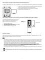
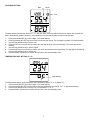
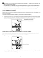
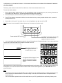
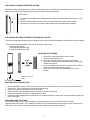
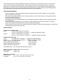
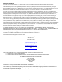
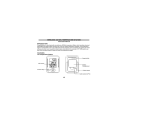
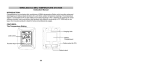
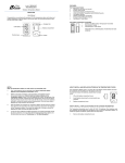
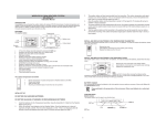
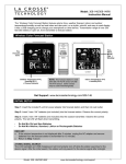
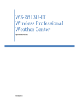
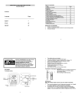
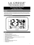
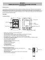
WS-8610
WIRELESS DATA LOGGING WEATHER STATION
Instruction Manual
INTRODUCTION:
Congratulations on purchasing this revolutionary 433MHz data logging weather station, which provides advanced datalogging and data-analysis functions for up to three outdoor temperature and humidity readings. The weather station is
connectable to PC by the COM port and data importing to your PC is allowed. By utilizing the advanced software provided
you might perform data analysis and statistics conveniently on your PC. With easy to use keys, this innovative product is
ideal for home and professional usages.
FEATURES:
The Weather Station
Hanging Hole
LCD screen
Battery
Compartment
Cable socket (to PC)
Function keys
Foldout stand
•
•
•
•
•
•
•
•
•
•
•
•
•
•
•
•
WWVB radio controlled time with manual setting option
Time zone option ±12 hours
Indoor and outdoor temperature display with MIN/MAX records and time of reception
Indoor and outdoor humidity display as RH% with MIN/MAX records
Data logging function – can store up to 3000 sets of temperature/humidity data
Connectable to PC (Com port) – data can be transferred to PC with the software (in CD ROM) provided
Can receive up to 3 outdoor transmitters
Time reception ON/OFF selectable
Dew point temperature displayed
Temperature & humidity high/low alarm function
12/24 hour time display
Year/ Month/ Day calendar display
Temperature display in ºF/ ºC
LCD contrast selectable
Low battery indicator
Table standing or wall mounting
The Remote Temperature Sensor
Remote transmission of outdoor temperature and humidity to the
weather station by 433 MHz signal.
•
Weather resistant casing
•
Wall mounting case
•
Should be mounted in a sheltered place (avoid direct rain and sunshine)
to ensure accurate measurements.
•
1
Battery
compartment
Battery cover
HOW TO INSTALL AND REPLACE BATTERIES IN THE WEATHER STATION
The indoor weather station uses 3 x AA, 1.5V batteries. To install and replace the batteries, please follow the steps below:
1. Insert finger or other solid object in the space at the bottom center of the
battery compartment and lift up to remove the cover.
2. Insert batteries observing the correct polarity (see marking).
3. Replace battery compartment cover.
SIZE AA LR6
SIZE AA LR6
SIZE AA LR6
HOW TO INSTALL AND REPLACE BATTERIES IN THE REMOTE TEMPERATURE/HUMIDITY SENSOR
The remote temperature/humidity sensor uses 2 x
AAA 1.5V batteries. To install and replace the
batteries, please follow the steps below:
Battery
compartment
Battery cover
1. Remove the battery cover
2. Insert the batteries, observing the correct polarity
(see battery compartment marking)
3. Replace the battery cover on the unit
BATTERY CHANGE:
User shall replace batteries of the indoor weather station when the battery low indicator is displayed at the LCD. If user
does not replace the batteries, working error may result.
Note:
•
•
•
•
After changing the batteries in the indoor weather station there is no need for user to reset the indoor weather station.
In fact, the indoor weather station can remember all remote temperature/humidity sensor information and sequence
as per the pervious set-up. However, user may be required to reset the desired LCD contrast, alarm on/off condition
and the clock (by re-entering the date and time manually or simply wait for the WWVB time signal).
The “average” value display for particular channel will only be calculated from the data after battery change.
User needs to carry out the re-learning of the particular remote temperature/humidity sensor after replacing batteries
in the remote temperature/humidity sensor. See “LEARNING/ REMOVING A SENSOR (CHANNEL)” for the
procedures of relearning a remote temperature/humidity sensor.
It is recommended to replace the batteries in all units on an annual basis to ensure optimum accuracy of these units.
Please participate in the preservation of the environment. Return used batteries to an authorized depot.
2
QUICK SET-UP GUIDE
Hint: Use fresh good quality alkaline batteries.
1. Have the indoor weather station and remote temperature/humidity sensor 3 to 5 feet apart.
2. Batteries should be out of both the indoor weather station and remote temperature/humidity sensor units for
10 minutes.
3. Place the batteries into the remote temperature/humidity sensor first then into the indoor weather station.
4. DO NOT PRESS ANY BUTTONS FOR 15 MINUTES.
In this time the indoor weather station and remote temperature/humidity sensor will start to talk to each other and the
display will show the indoor temperature/humidity and outdoor temperature/humidity. If the indoor weather station does
not display all information after the 15 minutes please retry the set up as stated above. After all information has been
displayed for 15 minutes you can place your sensor(s) outdoors and set your time.
Important Notes on Set-up and Operation
•
•
•
•
•
The remote temperature/humidity sensor should be placed in a dry, shaded area.
Fog and mist will not harm your remote temperature/humidity sensor but direct rain must be avoided.
The remote temperature/humidity sensor has a range of 330 feet. Any walls that the signal will have to pass through
will reduce distance. An outdoor wall or window can have up to 30 feet of resistance and an interior wall can have up
to 20 feet of resistance. Your distance plus resistance should not exceed 330 ft. in a straight line.
The remote temperature/humidity sensor transmits a signal every minute. After the batteries have been installed, the
indoor weather station will search for the signal for a duration of 5 minutes. If there is no temperature or humidity
reading in the OUTDOOR LCD after 5 minutes, make sure the units are within range of each other, or repeat the
battery installation procedure.
If a button is pressed before the indoor weather station receives the signal from the remote temperature/humidity
sensor, you will need to follow the battery installation procedure again.
To complete the set up of your new wireless weather station after the 15 minutes have passed please follow the steps that
follow in the Manual Settings section.
WWVB RADIO-CONTROLLED (ATOMIC) TIME
The NIST (National Institute of Standards and Technology—Time and Frequency Division) WWVB radio station is located
in Ft. Collins, Colorado, and transmits the exact time and date signal continuously throughout the United States at 60 kHz.
The signal can be received up to 2,000 miles away through the internal antenna in the Weather Station. However, due to
the nature of the Earth’s Ionosphere, reception is very limited during daylight hours. The weather station will search for a
signal every night when reception is best. The WWVB radio station derives its signal from the NIST Atomic clock in
Boulder, Colorado. A team of atomic physicists is continually measuring every second, of every day, to an accuracy of ten
billionths of a second per day. These physicists have created an international standard, measuring a second as
9,192,631,770 vibrations of a Cesium-133 atom in a vacuum. For more information on the atomic clock and WWVB
please see the NIST website at http://www.boulder.nist.gov/timefreq/stations/wwvb.htm.
3
FUNCTION KEYS:
There are 5 function keys on the weather station:
Minus key
SET key
Alarm key
Plus key
Mode key
Set key
•
In normal display mode, press and hold for 3 seconds to enter the manual setting mode for the following:
a.
b.
c.
d.
e.
f.
g.
h.
i.
j.
•
LCD contrast level
Time zone
Daylight saving time (on/ off)
Radio-controlled time reception (on/ off)
12/ 24-hour display
Time setting (hour and minute)
Calendar setting (year, month and day)
Temperature unit (°F/ °C) setting
Re-learning/ removing channels
Number of channels to be saved to memory
In view mode or alarm mode, press to go back to normal display mode
Plus (+) and Minus (–) key
•
•
In normal display mode, press to select a channel (the indoor sensor or one of the remote temperature/humidity
sensors)
Press to make adjustment (increase or decrease) in different manual settings and alarm setting
Mode key (MODE)
•
In normal display mode, press to toggle between the following view mode:
a.
b.
c.
d.
e.
•
•
•
•
Maximum record of a selected channel (the indoor sensor or one of the remote temperature/humidity sensors,
depending on the user’s selection)
Minimum record of a selected channel
Average humidity and temperature readings of a selected channel (over the last 100 values stored in memory)
The dew point temperature of a selected channel
History readings in the memory of a selected channel
In alarm setting mode, press to activate/ deactivate the temperature and humidity alarm.
In manual setting mode, press to go back to normal display mode
Press and hold for 3 seconds to reset Min/ Max record of a particular channel
Press and hold for 5 seconds to reset Min/ Max record of all channels
4
Alarm key (AL)
•
•
Press and hold for 3 seconds to enter the alarm setting mode.
In alarm setting mode, press to toggle between the following settings:
1.
2.
3.
4.
•
high humidity alarm
low humidity alarm
high temperature alarm
low temperature alarm
In manual setting mode, press to go back to normal display mode
LCD Screen:
The LCD screen is split into 4 sections displaying the time/ date, temperature, relatively humidity and memory status.
Time reception icon
(for WWVB time)
Outdoor transmitter identification
number
Buzzer-on icon
Calendar display
Time
Memory data display
(showing no. of sets of unread
data stored in memory)
Temperature reading in
ºF/ ºC
Relative humidity reading in
RH%
Outdoor data showing outdoor
sensor information is selected.
MANUAL SETTINGS:
In normal display mode, press and hold the SET key for 3 seconds to enter the manual setting mode for the following:
a.
b.
c.
d.
e.
f.
g.
h.
i.
j.
LCD contrast setting
Time zone setting
Daylight saving time on/ off setting
Radio-controlled time reception on/ off setting
12/ 24 hour format setting
Time setting (Hour and Minute)
Calendar setting (Year, Month and Day)
Temperature unit (°F/ °C) setting
Relearning or removing a remote temperature/humidity sensor
Number of sets of outdoor channel to be saved to the memory of the indoor weather station
5
LCD CONTRAST SETTING:
Digits flashing
The LCD contrast can be set within 8 levels, from LCD 0 to LCD7 (Default setting is “LCD 5”):
1. In normal display, press and hold the SET key until the digits “Lcd” starts flashing.
2. Use the plus (+) and minus (–) key to view all levels of contrast.
3. Select the desired LCD contrast. Confirm with the mode or Alarm (AL) key to go back to the normal display mode.
TIME ZONE SETTING:
Digits flashing
The time zone default of the weather station is “0”. To set a different time zone:
1.
2.
3.
4.
Press and hold the SET key until the digits “Lcd” starts flashing.
Press shortly the SET key one more time to enter the time zone setting. The digits “Zo” will be flashing.
Use the Plus and Minus key to set the time zone (-12 to 12 hr).
Press the Mode or Alarm key to confirm and go back to the normal display mode.
6
DAYLIGHT SAVING TIME ON/OFF SETTING
Note:
The function of day nighttime saving on/off is only applicable to specific area in United States using
WWVB time sources.
The “dS off” setting is used for area with no day nighttime saving within US while “dS On” settings is for those
area having day night time saving within US.
•
•
Digits flashing
1.
2.
3.
4.
Press and hold the SET key until the digits “Lcd” starts flashing.
Press shortly the SET key two times to enter the daylight saving time setting. The digit “dS” will be flashing.
Use the Plus and Minus key to set the daylight saving time function to “On” or “Off” mode.
Press the Mode or Alarm key to confirm and go back to the normal display mode.
TIME RECEPTION ON/OFF SETTING:
Digits flashing
In areas where reception of the WWVB time signal is not possible, the WWVB time reception function can be turned OFF.
The clock will then work as a normal Quartz clock. (Default setting is ON).
1.
2.
3.
4.
Press and hold the SET key until the digits “Lcd” starts flashing.
Press and release the SET key three times to enter the time reception time setting. The digit “rEc” will be flashing.
Use the Plus and Minus key to set the time reception function to on or off mode.
Press the Mode or Alarm key to confirm and go back to the normal display mode.
Note:
If the Time Reception function is turn OFF manually, the clock will not attempt any reception of the WWVB time as long as
the Time Reception OFF function is activated. The time reception icon and the “WWVB” icon will not be displayed on the
LCD
7
12/24-HOUR FORMAT SETTING:
Digits flashing
The time display can be selected to show hours in 12-hour or 24-hour settings. (Default 12-Hour)
1.
2.
3.
4.
Press and hold the SET key until the digits “Lcd” starts flashing.
Press and release the SET key four times to enter the time format setting. The digit “12h” will be flashing.
Use the Plus and Minus key to set the time shown in 12-hour or 24-hour format.
Press the Mode or Alarm key to confirm and go back to the normal display mode.
MANUAL TIME SETTING:
In case the weather station cannot detect the WWVB-signal (for example due to disturbances, transmitting distance, etc.),
the time can be manually set. The clock will then work as a normal Quartz clock.
Minutes flashing
Hour flashing
1.
2.
3.
4.
5.
6.
Press and hold the SET key until the digits “Lcd” starts flashing.
Press and release the SET key five times to enter the hour setting. The hour digit in the time LCD will be flashing.
Use the Plus and Minus key to set the hour.
Press the SET key one more time to confirm the hour and advance to the minute setting. The minute digit will be
flashing.
Use the Plus and Minus key to set the minute
Press the Mode or Alarm key to confirm and go back to the normal display mode.
Note: The unit will still try and receive the signal every day despite it being manually set. When it does receive the
signal, it will change the manually set time into the received time. During reception attempts the WWVB tower icon will
flash. If reception has been unsuccessful, then the WWVB tower icon will not appear but reception will still be attempted
the following hour.
8
CALENDAR SETTING:
Month
Date
Year
The date default of the weather station is 1. 1. in the year 2004. Once the radio-controlled time signals are received, the
date is automatically updated. However, if the signals are not received, the date can also be set manually.
1.
2.
3.
4.
5.
6.
7.
8.
Press and hold the SET key until the digits “Lcd” starts flashing.
Press and release the SET key seven times to enter the year setting. The year digit in the date LCD will be flashing.
Use the Plus and Minus key to set the year.
Press the SET key one more time to confirm the year and advance to the month setting. The month digit will be
flashing.
Use the Plus and Minus key to set the month.
Press the SET key one more time to confirm the month and advance to the day setting. The day digit will be flashing.
Use the Plus and Minus key to set the day.
Press the Mode or Alarm key to confirm and go back to the normal display mode.
TEMPERATURE UNIT SETTING (°F/ °C):
Digit flashing
The temperature display can be selected to show temperature data in °F or °C (Default °F).
1.
Press and hold the SET key until the digits “Lcd” starts flashing.
2.
Press and release the SET key ten times to enter the temperature unit setting. The “°F” digit will be flashing.
3.
Use the Plus and Minus key to set the unit of temperature in °F or °C.
4.
Press the Mode or Alarm key to confirm and go back to the normal display mode.
9
LEARNING/ REMOVING A REMOTE TEMPERATURE/HUMIDITY SENSOR (CHANNEL)
After replacement of batteries of a particular remote temperature/humidity sensor, it is necessary to learn the remote
temperature/humidity sensor again in the learning mode. On the other hand, when a user wants to decrease the number
of remote temperature/humidity sensors to be applied, they may remove the remote temperature/humidity sensors so that
the data from this channel will not be displayed in the indoor weather station. The below procedures describe how to “relearn” or “remove” a channel:
1.
2.
Press and hold the SET key until the digits “Lcd” starts flashing.
Press shortly the SET key eleven times to enter Learn/ Remove setting of channels. The digits “Lrn”, “CH” and the
channel icons will be flashing.
Digit flashing
Flashing
3.
4.
5.
6.
Press Plus to select Channel 1. The digit ”1” will be flashing.
Press Plus to set Channel 1 to “Re-learn” state (The channel icon will be flashing), or press Minus to remove
Channel 1 (The channel icon will disappear).
Press SET key to select Channel 2. The digit “2” will be flashing.
Repeat the above steps to Channel 2 to 3, setting them either in “re-learnt” or “removed” state.
Note: Once a channel is removed, the indoor weather station will be “disconnected” from the channel and the data
transmitted by this channel cannot be viewed at the indoor weather station.
THE NUMBER OF REMOTE TEMPERATURE/HUMIDITY SENSOR TO BE SAVED INTO THE SYSTEM MEMORY
Digits flashing
Up to 3 remote temperature/humidity sensors can be received by the indoor weather station. The user may decide the
number of remote temperature/humidity sensor data to be saved to the permanent memory of the indoor weather station.
For instant, user may apply 3 remote temperature/humidity sensors but set to save the data only from 2 particular remote
temperature/humidity sensors. To set the number of remote temperature/humidity sensor s whose data are to be saved in
the system memory:
1.
2.
3.
4.
Press and hold the SET key until the digits “Lcd” starts flashing.
Press and release the SET key twelve times to enter remote temperature/humidity sensor number setting. The digit
“Enr” will be flashing.
Use the Plus and Minus key to select the number of remote temperature/humidity sensor to be used with the
weather station (up to 3 transmitters)
Press the SET key one more time to confirm and go back to the normal display mode.
10
Note:
•
If user has set “Enr = 2” and three remote temperature/humidity sensors are on, the data only from channel No. 1 and
2 will be saved in the system memory.
•
On the other hand, if user has initially applied 3 remote temperature/humidity sensors but then removed Channel 2,
the indoor weather station will thereafter display “--.-“ for Channel 2. And if the user has chosen “Enr = 2, the data
from Channel 1 to 2 will be stored in the memory, instead of Channel 1 and 3. The data stored in the memory for
Channel 2 will be “--.-“.
•
After the “Enr” number has been changed, the history data will be cleared and “mem” will be reset to “0000”.
TO EXIT THE MANUAL SETTING MODE
Press the Mode key or Alarm key to exit the manual setting mode anytime during the manual setting. The mode will return
to the normal time display.
TOGGLING BETWEEN DIFFERENT CHANNELS (INDOOR AND OUTDOOR CHANNELS):
1.
Press the Plus or Minus key to toggle between the temperature and humidity readings of the indoor channel and the
remote temperature/humidity sensor channel(s). The channel identification icon (“in”, “out 1”, “out 2”, “out 3”) will be
displayed in the upper right of the screen indicating that the particular channel is now being selected.
The temperature and humidity
readings of Outdoor transmitter
No.1 is now shown
VIEWING VARIOUS TYPE OF TEMP/HUMDITY READINGS OF A SELECTED CHANNEL:
After a particular channel (the indoor sensor or one of the remote temperature/humidity sensors) has been selected by
pressing the Plus or Minus key, the following modes of data may be viewed by user:
a.
The Max temperature and Max humidity
Max icon flashing
In normal display mode, press the mode key once. The maximum temperature and maximum humidity measured by
the remote temperature/humidity sensor channel, and the date and time of the maximum temperature recorded will
be displayed. The “max” icon will be flashing.
11
b.
The Min temperature and Min humidity
Min icon flashing
In normal display mode, press the mode key two times. The minimum temperature and humidity measured by the
remote temperature/humidity sensor channel, and the date and time of the minimum temperature recorded will be
displayed. The “min” icon will be flashing.
c.
The average value of the last 100 readings
Average icon flashing
In normal display mode, press the mode key three times. The average temperature and humidity value of the data
which have been saved in the system memory will be displayed. The “avg” icon will be flashing. If the remote
temperature/humidity sensor channel is not set to be saved in the system memory, no average value will be
estimated and “--.-“ will be shown.
Note:
The “Average” value displayed for a particular remote temperature/humidity sensor channel will be
calculated from only the new data being recorded after battery change.
d.
The dew point temperature
Dew point temperature icon
In normal display mode, press the mode key four times. The dew point temperature will be displayed next to the
flashing “td” icon.
12
e.
The history data sets of temperature and humidity
History data icon flashing
In normal display mode, press the mode key five times. The “hist” icon will be flashing and the last recorded
temperature and humidity reading with the time of record will be displayed.
By pressing the Minus key, the previous sets of readings which were measured at the user-selected recording
intervals may be viewed.
If the remote temperature/humidity sensor channel is not set to be saved in the system memory, no history values
will be displayed and “--.-“ will be shown on LCD.
ALARM PROGRAMMING FOR INDOOR/ OUTDOOR TEMPERATURE AND HUMIDITY
The indoor weather station will allow users to set a range of specific alarms to meet specific temperature and humidity
conditions set by the user.
For example, user may set the high and low temperature alarm point at 85°F and 65°F respectively. Then the alarm will
sound once the temperature is higher than 85°F or lower than 65°F.
To set the high humidity alarm:
1.
2.
3.
In normal display, press the Plus or Minus key to select a temperature/humidity sensor channel (the
temperature/humidity sensor at the indoor weather station or one of the remote temperature/humidity sensors).
Press and hold the Alarm key for about 3 second to enter high humidity alarm setting. The humidity digits, high limit
icon and the alarm icon will start flashing.
Press the Mode key to select to “activate” or “deactivate” the high humidity alarm. (“Alarm On” icon displayed
represents the alarm is on).
Humidity digit
flashing
High limit icon
Alarm On icon (If this icon does
not show, the alarm is set to be
off)
4.
5.
Press the Plus or Minus key to set the desired value of the high humidity alarm threshold point.
Press SET key to return to the normal display or press the Alarm key to enter the low humidity alarm setting.
13
To set the low humidity alarm:
1.
2.
In normal display, press the Plus or Minus key to select a temperature/humidity sensor channel (the
temperature/humidity sensor at the indoor weather station or one of the remote temperature/humidity sensors).
Press and hold the Alarm key for about 3 second to enter high humidity alarm setting. Then press the Alarm key
shortly one more time to enter the low humidity alarm setting. The humidity digits, low limit icon and the alarm icon
will start flashing.
Low limit icon
3.
4.
5.
Humidity digit flashing
Press the Mode key to select to “activate” or “deactivate” the low humidity alarm. (“Alarm On” icon displayed
represents the alarm is on)
Press the Plus or Minus key to set the desired value of the low humidity alarm point.
Press SET key to return to the normal display or press the Alarm key to enter the high temperature alarm setting.
To set the high temperature alarm:
1. In normal display, press the Plus or Minus key to select a temperature/humidity sensor (the temperature/humidity
sensor at the indoor weather station or one of the remote temperature/humidity sensors)
2. Press and hold the Alarm key for about 3 second to enter high humidity alarm setting. Then press shortly the Alarm
key two more times to enter the high temperature alarm setting. The temperature digits, high limit icon and the alarm
icon will start flashing.
High limit icon
Temperature digits
flashing
3.
4.
5.
Press the Mode key to select to “activate” or “deactivate” the high temperature alarm. (“Alarm On” icon displayed
represents the alarm is on)
Press the Plus or Minus key to set the desired value of the high temperature alarm point.
Press SET key to return to the normal display or press the Alarm to enter the low temperature alarm setting.
14
To set the low temperature alarm:
1. In normal display, press the Plus or Minus key to select a temperature/humidity sensor (the temperature/humidity
sensor at the indoor weather station or one of the remote temperature/humidity sensors)
2. Press and hold the Alarm key for about 3 second to enter high humidity alarm setting. Then press shortly the Alarm
key three more times to enter the low temperature Alarm setting. The temperature digits, low limit icon and the alarm
icon will start flashing.
Low limit icon
Temperature digits
flashing
3. Press the Mode key to select to “activate” or “deactivate” the low temperature alarm. (“Alarm On” icon displayed
represents the alarm is on)
4. Press the Plus or Minus key to set the desired value of the low temperature alarm point.
5. Press SET key to return to the normal display.
Note:
•
•
•
•
The alarms allow you to set individually the high or low threshold as you require. For example, you can set the
thresholds for temperature to 85°F (high) and 65°F (low), while only activating high temp alarm and deactivating low
temp alarm. In this case, the alarm will not trigger when temperature is lower than 65°F yet will trigger when temp is
higher than 85.0°F.
When the temperature or humidity is sensed to be out of the pre-set threshold value, the alarm will sound and the
alarm icon will be present on LCD. You may press any key to stop the buzzer. If no key is pressed, the buzzer will
beep for two minutes however the alarm signal icon will flash until the temperature or humidity is within the pre-set
range again.
Once an alarm is triggered, the display switches to the latest triggered temperature/humidity sensor channel. In
addition, the high/ low limit icon and IN/ OUT icon is flashing as long as the alarm condition is met.
If an alarm is triggered, the alarm icon will be flashing until the temperature and/or humidity is back to the conditions
within the preset threshold values.
The Alarm icon and the corresponding
high or low alarm icons will flash once
the current temperature or humidity is
out of the pre-set threshold value
15
MEMORY CAPACITY
The indoor weather station provides data-logging function. The temperature and humidity data are saved into the Memory
of the indoor weather station at 5-minute intervals (recording one data set every five minute). The number of sets of data
stored is shown at the ''mem'' display.
The data-storing capacity for various numbers of remote temperature/humidity sensors used is listed below:
No. of transmitters used
0 or 1
2
3
Max No. of sets of temperature and
humidity data stored for each
transmitter and the indoor sensor
~3260
~2510
~2170
Note:
•
After the capacity has been reached, the first data (the oldest sets) will be overwritten by the latest one and so on.
CLEARING DATA IN THE INDOOR WEATHER STATION
CLEARING THE MAX/MIN TEMPERATURE AND HUMIDITY DATA OF A PARTICULAR REMOTE
TEMPERATURE/HUMIDITY SENSOR CHANNEL
To clear the max/min data of a remote temperature/humidity sensor channel:
1.
2.
Press the Plus or Minus key to select a remote temperature/humidity sensor channel.
Press and hold the Mode key for 3 second. The maximum and minimum temperature/ humidity data and the time of
record will be reset to the current value.
CLEARING THE MAX/MIN TEMPERATURE AND HUMIDITY DATA OF ALL REMOTE TEMPERATURE/HUMIDITY
SENSOR CHANNELS
To clear the max/min data of all remote temperature/humidity sensor channels:
1. Press and hold the Mode key for 5 second. The maximum and minimum temperature/ humidity data and the time of
record will be reset to the current value.
CLEARING ALL STORED TEMPERATURE AND HUMIDITY DATA (FROM TEMPORARY MEMORY OF THE INDOOR
WEATHER STATION)
The on-going temperature and humidity data are stored at the ring buffer memory (a temporary memory area where the
latest data will displace the oldest data once the memory capacity is reached). To clear this memory, the following step
MUST be performed:
1. Press both the Plus key and SET key and hold for about 2 seconds.
2. The temperature and humidity records of all temperature/humidity sensor channels (indoor and the outdoor
temperature/humidity sensor channels) will be cleared.
3. The average and history data will no longer exist.
4. The memory display will show “mem 0000” after the data has been cleared.
Note:
The maximum/ minimum temperature and humidity data will not be cleared.
16
CLEARING ALL DATA AND SETTINGS OF THE INDOOR WEATHER STATION FROM THE PERMANENT MEMORY
(FACTORY RESET)
The factory reset needs to be launched if a malfunction of the indoor weather station occurs.
To reset the weather station:
1. Ensure that the indoor weather station is in the normal display mode, not displaying max, min, or history. And the unit
is not making any WWVB or HF (remote temperature/humidity sensor reception).
2. Press the Set, plus, minus and mode key and hold for 3 seconds in following order.
3. The SET key must be pressed and held first, then the other three key must be pressed and held within 1 second of
pressing the SET key.
4. Next hold the four keys for 3 seconds until you see running digits at top right area of the LCD.
Note: If the reset is not successfully initiated, please retry from step one (1) above again.
Press and hold SET key first
Immediately press these 3 keys at the
same time. Then hold the 4 keys
together for about 3 seconds.
3. The running digits will be displayed for about 6 minutes, followed by the full segment display. You are then required to
remove and re-insert the batteries to complete the restart of the unit.
The display will show some
running digits when the
weather station is reset.
Full segment will be displayed- user
needs to remove and re-insert
batteries to restart the weather
station.
After batteries are re-inserted, the station will automatically launch into the learn mode. The signal reception indicator will
be displayed. You must now reset the indoor weather station for the desired application. (See ”SETTING UP” in the
previous section).
Note:
•
•
If the battery level is low, the digits “No EPr” may be displayed on the LCD after resetting, indicating that the power is
too low for the indoor weather station to function normally. In this case, the batteries need to be replaced before
resetting the unit.
It is recommended to upload and save all the useful data to your PC (if possible) before performing a factory reset.
17
USING THE WEATHER STATION WITH PC
With the aid of the software supplied, the indoor weather station may provide the following additional functions.
1. Importing data from the indoor weather station to a PC.
2. Printing the history file.
Procedures to install the software to a PC and application of the software are described in the user manual of the PC
software.
ABOUT THE OUTDOOR TRANSMITTER
The range of the remote temperature/humidity sensor may be affected by the temperature. At cold temperatures the
transmitting distance may be decreased. Please bear this in mind when positioning the remote temperature/humidity
sensors. The battery life may be reduced as well as the power for the remote temperature/humidity sensor in extreme hot
and cold temperatures.
CHECKING FOR 433MHz RECEPTION
If the outdoor temperature/humidity data is not received within three minutes after setting up the weather station (or the
outdoor display shows “- -. -” in the outdoor section of the indoor weather station after 3 failed attempts during normal
operation), please check the following items:
1.
2.
3.
The distance of the indoor weather station or remote temperature/humidity sensors should be at least 6 feet (2
meters) away from any interfering sources such as computer monitors or TV sets.
Avoid placing the transmitters onto or in the immediate proximity of metal window frames.
Using other electrical products such as headphones or speakers operating on the 433MHz-signal frequency may
prevent correct signal transmission or reception. Neighbors using electrical devices operating on the 433MHz-signal
frequency can also cause interference.
Note: When the 433MHz signal is received correctly, do not re-open the battery cover of either the remote
temperature/humidity sensor or indoor weather station. The batteries may spring free from the contacts and force
a false reset. Should this happen accidentally reset all units (see “SETTING UP” above) or transmission
problems may occur.
The transmission range is around 330 feet (100 meters) from the remote temperature/humidity sensor to the indoor
weather station (in open space). However, this depends on the surrounding environment and interference levels. If no
reception is possible despite the observation of these factors, all system units have to be reset (see “SETTING UP”
above).
18
POSITIONING THE INDOOR WEATHER STATION:
The indoor weather station provides the option of table standing or wall mounting the unit. Before wall mounting, please
check that the outdoor temperature(s) can be received from the desired location(s).
To wall mount:
1. Fix a screw (not supplied) into the desired wall, leaving the head extended out by about ¼ inch
(5mm).
2. Place the indoor weather station onto the screw and pull down gently to lock into place.
3. Remember to ensure that the indoor weather station locks into place before releasing.
POSITIONING THE REMOTE TEMPERATURE/HUMIDITY SENSOR
The remote temperature/humidity sensor is supplied with a holder that may be attached to a wall with the screws supplied.
The remote temperature/humidity sensor can be mounted in three ways:
• Mounting with screws
• Mounting with adhesive tape
• Using the bracket as a stand
MOUNTING WITH SCREWS
1. Remove the mounting bracket from the remote
temperature/humidity sensor.
2. Place the mounting bracket over the desired location.
3. Through the screw holes of the bracket, mark the mounting
surface with a pencil.
4. Screw mounting bracket onto the mounting surface. Ensure
that the screws are flush with the bracket.
5. Insert the remote temperature/humidity sensor into the
bracket.
Table stand/wall mount
bracket
MOUNTING WITH ADHESIVE TAPE
1. With a nonabrasive solution, clean and dry the back of the mounting bracket and the mounting surface to ensure a
secure hold. The mounting surface should be smooth and flat.
2. Remove the protective strip from one side of the tape.
3. Adhere the tape to the designated area on the back of the mounting bracket.
4. Remove the protective strip from the other side of the tape.
5. Position the remote temperature/humidity sensor in the desired location, ensuring that the indoor weather station can
receive the signal.
MOUNTING USING THE STAND
The mounting bracket can be used as a stand by simply attaching the bracket to the bottom of the remote
temperature/humidity sensor. Once snapped in place the remote temperature/humidity sensor can then be placed on a
shelf, table or other surface where the temperature and humidity measurements are desired.
19
The mounting surface can affect the transmission range. For example, the unit is attached to a piece of metal; it may
either reduce or increase the transmitting range. For this reason, we recommend not placing the unit on any metal
surfaces or in any position where a large metal or highly polished surface is in the immediate proximity (garage doors,
double glazing etc.). Before securing in place, please ensure that the indoor weather station can receive the signal from
the remote temperature/humidity sensor at the positions that you wish to situate them.
CARE AND MAINTENANCE:
•
•
•
•
•
•
Extreme temperatures, vibration and shock should be avoided as these may cause damage to the units and give
inaccurate forecasts and readings.
When cleaning the display and casings, use a soft damp cloth only. Do not use solvents or scouring agents as they
may mark the LCD and casings.
Do not submerge the units in water.
Immediately remove all low powered batteries to avoid leakage and damage. Replace only with new batteries of the
recommended type.
Do not make any repair attempts to the units. Return it to their original point of purchase for repair by a qualified
engineer. Opening and tampering with the units may invalidate their guarantee.
Do not expose the units to extreme and sudden temperature changes, this may lead to rapid changes in forecasts and
readings and thereby reduce their accuracy.
SPECIFICATIONS:
Temperature measuring range:
Indoor
: -9.9ºC to +59.9ºC with 0.1°C resolution
+14ºF to +139.8ºF with 0.2ºF resolution (“- -” displayed if outside this range)
Outdoor
: -29.9ºC to +69.9ºC with 0.1°C resolution
-21.8ºF to +157.8ºF with 0.2ºF resolution (“- -” displayed if outside this range)
Humidity measuring range:
Indoor
: 1% to 99% with 1% resolution (“- -“ displayed if outside this range)
Outdoor
: 1% to 99% with 1% resolution (“- -“ displayed if outside this range)
Indoor temperature checking intervals
:
Every 15 seconds
Indoor humidity checking intervals
:
Every 20 seconds
Outdoor temperature checking interval
:
Every 5 minutes
Outdoor humidity checking interval
:
Every 5 minutes
Transmission range : up to 330 feet (100 meters) (open space)
Power consumption: (alkaline batteries recommended)
Weather station
: 3 x AA, 1.5V
Transmitter
: 2 x AAA, 1.5V
Dimensions (H x W x D):
Weather station
: 5.1” x 4.10” x 1.15” (128.9 x 104.2 x 29.5 mm)
Transmitter
: 3.15” x 2.20” x 0.95” (80 x 56 x 24 mm)
20
WARRANTY INFORMATION
La Crosse Technology, Ltd provides a 1-year limited warranty on this product against manufacturing defects in materials and workmanship.
This limited warranty begins on the original date of purchase, is valid only on products purchased and used in North America and only to the original
purchaser of this product. To receive warranty service, the purchaser must contact La Crosse Technology, Ltd for problem determination and service
procedures. Warranty service can only be performed by a La Crosse Technology, Ltd authorized service center. The original dated bill of sale must be
presented upon request as proof of purchase to La Crosse Technology, Ltd or La Crosse Technology, Ltd’s authorized service center.
La Crosse Technology, Ltd will repair or replace this product, at our option and at no charge as stipulated herein, with new or reconditioned parts or
products if found to be defective during the limited warranty period specified above. All replaced parts and products become the property of La Crosse
Technology, Ltd and must be returned to La Crosse Technology, Ltd. Replacement parts and products assume the remaining original warranty, or
ninety (90) days, whichever is longer. La Crosse Technology, Ltd will pay all expenses for labor and materials for all repairs covered by this warranty. If
necessary repairs are not covered by this warranty, or if a product is examined which is not in need or repair, you will be charged for the repairs or
examination. The owner must pay any shipping charges incurred in getting your La Crosse Technology, Ltd product to a La Crosse Technology, Ltd
authorized service center. La Crosse Technology, Ltd will pay ground return shipping charges to the owner of the product to a USA address only.
Your La Crosse Technology, Ltd warranty covers all defects in material and workmanship with the following specified exceptions: (1) damage caused by
accident, unreasonable use or neglect (including the lack of reasonable and necessary maintenance); (2) damage occurring during shipment (claims
must be presented to the carrier); (3) damage to, or deterioration of, any accessory or decorative surface; (4) damage resulting from failure to follow
instructions contained in your owner’s manual; (5) damage resulting from the performance of repairs or alterations by someone other than an authorized
La Crosse Technology, Ltd authorized service center; (6) units used for other than home use (7) applications and uses that this product was not
intended or (8) the products inability to receive a signal due to any source of interference.. This warranty covers only actual defects within the product
itself, and does not cover the cost of installation or removal from a fixed installation, normal set-up or adjustments, claims based on misrepresentation by
the seller or performance variations resulting from installation-related circumstances.
LA CROSSE TECHNOLOGY, LTD WILL NOT ASSUME LIABILITY FOR INCIDENTAL, CONSEQUENTIAL, PUNITIVE, OR OTHER SIMILAR
DAMAGES ASSOCIATED WITH THE OPERATION OR MALFUNCTION OF THIS PRODUCT. THIS PRODUCT IS NOT TO BE USED FOR MEDICAL
PURPOSES OR FOR PUBLIC INFORMATION. THIS PRODUCT IS NOT A TOY. KEEP OUT OF CHILDREN’S REACH.
This warranty gives you specific legal rights. You may also have other rights specific to your State. Some States do no allow the exclusion of
consequential or incidental damages therefore the above exclusion of limitation may not apply to you.
For warranty work, technical support, or information contact:
La Crosse Technology
2809 Losey Blvd. S.
La Crosse, WI 54601
Phone: 608.782.1610
Fax: 608.796.1020
e-mail:
[email protected]
(warranty work)
[email protected]
(information on other products)
web:
www.lacrossetechnology.com
FCC DISCLAIMER
This device complies with part 15 of the FCC rules. Operation is subject to the following two conditions:
(1) This device may not cause harmful interference.
(2) This device must accept any interference received, including interference that may cause undesired operation.
FCC ID: OMO-01RX (Receiver), OMO-01TX (transmitter)
Freq. 433.92 MHz
La Crosse Technology
Made in China
WS-8610
All rights reserved. This handbook must not be reproduced in any form, even in excerpts, or duplicated or processed using electronic,
mechanical or chemical procedures without written permission of the publisher.
This handbook may contain mistakes and printing errors. The information in this handbook is regularly checked and corrections made in the
next issue. We accept no liability for technical mistakes or printing errors, or their consequences.
All trademarks and patents are acknowledged.
21
INSTRUCTION MANUAL FOR DATA RECORDER SOFTWARE (WS-8610)
Introduction
This weather station together with the Data Recorder software is a high quality, easy to use data-logging system.
After installing the program on this CD-ROM to your PC, you will get all the soft copy of the stored data in all preset outdoor channels and the indoor
channel. To operate the system, simply use the PC cable supplied and connect the weather station to your PC using the desired COM.
PC System Requirements
Cable socket
To install the Data Recorder software onto your PC, the minimum requirements are as follows:
•
Operating system: Windows 98 or later version
•
Processor: Pentium 166 MHz or above
•
CD-ROM Drive
•
Microsoft Excel 5.0 95 or later version
Installation of the Data Recorder Software
First check to ensure the indoor weather station and the remote temperature/humidity sensors are functioning normally.
Be sure to replace batteries of the indoor weather station when the battery low indicator is displayed at the LCD. Failure to do so may result in errors in
the operation of the indoor weather station and Data Recorder software.
Note:
•
After changing the batteries in the indoor weather station there is no need to reset the indoor weather station. In fact, the indoor weather station can
remember all remote temperature/humidity sensor information and sequence as per the pervious set-up. It may be required to reset the desired
LCD contrast, Alarm On/Off condition and the Clock (by re-entering the date and time manually or simply wait for the WWVB time signal).
If the battery of a remote temperature/humidity sensor is drained you must re-learning that particular remote temperature/humidity sensor after
replacing the batteries.
(See “LEARNING/ REMOVING A REMOTE TEMPERATURE/HUMDITY SENSOR (CHANNEL)” in the main user manual for the procedures of relearning a remote temperature/humidity sensor (channel).)
21
Next install the Data Recorder software as follows:
1.
Switch on the PC and insert the CD-ROM into the CD-ROM Drive.
2.
The CD-ROM will automatically run and the following screen will be displayed:
Click this button to start the
installation
3.
Next click the button below the text "Click to install Data recorder software" to start the installation.
4.
The dialogue box pictured below will be displayed.
5.
Choose the desired program language (English, German or French).
6.
Follow the steps as instructed by the Install menu to finish the installation.
7.
A shortcut icon “Data Recorder“, as shown below, will appear on your PC desktop after successful installation.
Data Recorder
Note:
In case the automatic installation routine does not start after the CD-ROM is inserted, click the “Start” button in MS Windows. Next run the "autorun.exe"
file in the CD-ROM manually to start the installation of the software. Then follow the steps as advised by the program to complete the installation.
22
Setting the parameter of the Data Recorder software
Before importing data from indoor weather station, you may set the display format in the Options mode:
1.
Click the “Extras” in the menu bar. Then user may advance to the “Options menu”.
2.
In the “Options” mode, the following parameters can be altered.
Display format:
a.
b.
c.
d.
Language – (English, German or French to select)
Date format (different date format to select)
Time format (different time format to select)
Temperature unit (°F / °C)
23
Data storing options:
a.
b.
Port ID (COM1 to 4) – decide which COM port to be used
Choosing recoding history file – Once you import a set of data from the indoor weather station the first time, a history file* will be generated
by the program and the data will be stored in it. When importing additional data to your PC, the new data will still be stored and accumulated
in the same history file as before.
You will need to create a new file in the “Recording History file” (see below figure), if you would like to place the additional data in a
separate file. If done in this manor the newly imported data will be stored in this new file.
Click this button to choose the old
data files or create a new file. Then
data can be imported into the old
data files or a new file.
Note:
*This history file carries data only for the Data Recorder program and can only be viewed with this program. If you need to use the data in another
program, for instant Microsoft Excel, you will need to “export” the data in a Text file first (See Exporting the data to PC below).
Menu bar and function button
Menu bar
Open file button
Import button
Export
button
Delete
button
Print button
Opening files
By clicking the “Open file” button you may choose to view the previously saved history files.
Note:
If user wants to place additional data into a new separated file, he shall advance to the Options mode and create a new file name first (See “Setting the
parameter of the Data Recorder software“ above).
24
Importing data from the indoor weather station to the PC
1.
2.
3.
After successful installation, you can open the Data Recorder program by clicking the “Data Recorder” icon.
The below screen will be displayed.
The number of channels shown will be the number that you have set in the indoor weather station for the “Number of remote
temperature/humidity sensors” to be saved in the system memory”.
Indoor channel
Channel No.
2.
Click the “Data” in menu bar and then click “Import” or simply click the “Import” button. Then the data stored in the indoor weather station will be
transferred to the PC and shown on the screen.
25
The data stored in the indoor weather station is now displayed in the program, with the date and time of record and the corresponding temperature and
humidity readings.
Note:
In rare occasions, defects may appear in the memory of the indoor weather station and affect the normal data transfer. If you find that the data cannot be
successfully imported from the indoor weather station to PC after you perform the correct steps for several times, please reset the indoor weather station
(factory reset). ***Please keep in mind that once the indoor weather station is reset, all the stored data will be cleared.
Exporting data to PC (saving the data in a user-generated file in PC)
You may save the data in a file so that it can be used in other programs later:
1.
Click the “Export” option in the menu bar or simply click the Export button.
2.
Decide the destination in which the data to be saved. Then the data will be stored in a Text file in the selected destination. The Text file is
compatible to the software Microsoft Excel where user may conveniently study and utilize the data.
Decide a destination of the file to be saved
TEXT File opened in Microsoft Excel
Note:
In Microsoft Excel, you may need to adjust the Text import setting to make a spreadsheet format with each figure carried in a single cell. (See “Open the
Text file in Microsoft Excel”)
26
Open the data file in Microsoft Excel
Once you have created a Text file for data you can view the file and convert it into Microsoft Excel file by the following steps:
1.
Open Microsoft Excel first. Then choose to open a Text file.
Choose “Text files”
2.
Next go to the Text import setting and see the below screen. Click “Next” to advance to the next screen.
3.
Next choose the “Semicolon” as delimiters and then press “Finish”.
Select the “Semicolon”, then press “Finish” button
27
4.
After finishing the Text import setting, each data will be carried in a separate cell. In addition you may now save the data in an Excel formatted file.
Editing/ deleting the imported data
You may edit or delete the imported data if necessary in the program. To edit the data:
1.
2.
Highlight the particular data row.
Move the cursor to point at the figure to be altered and click the left button (of the mouse) three times consecutively. The figure will be highlighted
and you can enter in a new figure.
This figure is highlighted and can be altered
You may also delete a particular row of data by first highlighting it and then clicking the “Delete” icon in the menu bar.
Printing the data file
The Data Recorder program enables you to print the data. Click the Print button to print the currently viewed data file.
28
WARRANTY INFORMATION
La Crosse Technology, Ltd provides a 1-year limited warranty on this product against manufacturing defects in materials and workmanship.
This limited warranty begins on the original date of purchase, is valid only on products purchased and used in North America and only to the original
purchaser of this product. To receive warranty service, the purchaser must contact La Crosse Technology, Ltd for problem determination and service
procedures. Warranty service can only be performed by a La Crosse Technology, Ltd authorized service center. The original dated bill of sale must be
presented upon request as proof of purchase to La Crosse Technology, Ltd or La Crosse Technology, Ltd’s authorized service center.
La Crosse Technology, Ltd will repair or replace this product, at our option and at no charge as stipulated herein, with new or reconditioned parts or
products if found to be defective during the limited warranty period specified above. All replaced parts and products become the property of La Crosse
Technology, Ltd and must be returned to La Crosse Technology, Ltd. Replacement parts and products assume the remaining original warranty, or
ninety (90) days, whichever is longer. La Crosse Technology, Ltd will pay all expenses for labor and materials for all repairs covered by this warranty. If
necessary repairs are not covered by this warranty, or if a product is examined which is not in need or repair, you will be charged for the repairs or
examination. The owner must pay any shipping charges incurred in getting your La Crosse Technology, Ltd product to a La Crosse Technology, Ltd
authorized service center. La Crosse Technology, Ltd will pay ground return shipping charges to the owner of the product to a USA address only.
Your La Crosse Technology, Ltd warranty covers all defects in material and workmanship with the following specified exceptions: (1) damage caused by
accident, unreasonable use or neglect (including the lack of reasonable and necessary maintenance); (2) damage occurring during shipment (claims
must be presented to the carrier); (3) damage to, or deterioration of, any accessory or decorative surface; (4) damage resulting from failure to follow
instructions contained in your owner’s manual; (5) damage resulting from the performance of repairs or alterations by someone other than an authorized
La Crosse Technology, Ltd authorized service center; (6) units used for other than home use (7) applications and uses that this product was not
intended or (8) the products inability to receive a signal due to any source of interference.. This warranty covers only actual defects within the product
itself, and does not cover the cost of installation or removal from a fixed installation, normal set-up or adjustments, claims based on misrepresentation by
the seller or performance variations resulting from installation-related circumstances.
LA CROSSE TECHNOLOGY, LTD WILL NOT ASSUME LIABILITY FOR INCIDENTAL, CONSEQUENTIAL, PUNITIVE, OR OTHER SIMILAR
DAMAGES ASSOCIATED WITH THE OPERATION OR MALFUNCTION OF THIS PRODUCT. THIS PRODUCT IS NOT TO BE USED FOR MEDICAL
PURPOSES OR FOR PUBLIC INFORMATION. THIS PRODUCT IS NOT A TOY. KEEP OUT OF CHILDREN’S REACH.
This warranty gives you specific legal rights. You may also have other rights specific to your State. Some States do no allow the exclusion of
consequential or incidental damages therefore the above exclusion of limitation may not apply to you.
For warranty work, technical support, or information contact:
La Crosse Technology
2809 Losey Blvd. S.
La Crosse, WI 54601
Phone: 608.782.1610
Fax: 608.796.1020
e-mail:
[email protected]
(warranty work)
[email protected]
(information on other products)
web:
www.lacrossetechnology.com
La Crosse Technology
Made in China
Data Recorder Software for Model
WS-8610
All rights reserved. This handbook must not be reproduced in any form, even in excerpts, or duplicated or processed using electronic,
mechanical or chemical procedures without written permission of the publisher.
This handbook may contain mistakes and printing errors. The information in this handbook is regularly checked and corrections made in the
next issue. We accept no liability for technical mistakes or printing errors, or their consequences.
All trademarks and patents are acknowledged.
29